CN114220384B - Display panel, driving method thereof, and display device - Google Patents
Display panel, driving method thereof, and display deviceDownload PDFInfo
- Publication number
- CN114220384B CN114220384BCN202010990185.0ACN202010990185ACN114220384BCN 114220384 BCN114220384 BCN 114220384BCN 202010990185 ACN202010990185 ACN 202010990185ACN 114220384 BCN114220384 BCN 114220384B
- Authority
- CN
- China
- Prior art keywords
- light emitting
- emitting devices
- row
- coupled
- display panel
- Prior art date
- Legal status (The legal status is an assumption and is not a legal conclusion. Google has not performed a legal analysis and makes no representation as to the accuracy of the status listed.)
- Active
Links
Images


Classifications
- G—PHYSICS
- G09—EDUCATION; CRYPTOGRAPHY; DISPLAY; ADVERTISING; SEALS
- G09G—ARRANGEMENTS OR CIRCUITS FOR CONTROL OF INDICATING DEVICES USING STATIC MEANS TO PRESENT VARIABLE INFORMATION
- G09G3/00—Control arrangements or circuits, of interest only in connection with visual indicators other than cathode-ray tubes
- G09G3/20—Control arrangements or circuits, of interest only in connection with visual indicators other than cathode-ray tubes for presentation of an assembly of a number of characters, e.g. a page, by composing the assembly by combination of individual elements arranged in a matrix no fixed position being assigned to or needed to be assigned to the individual characters or partial characters
- G09G3/22—Control arrangements or circuits, of interest only in connection with visual indicators other than cathode-ray tubes for presentation of an assembly of a number of characters, e.g. a page, by composing the assembly by combination of individual elements arranged in a matrix no fixed position being assigned to or needed to be assigned to the individual characters or partial characters using controlled light sources
- G09G3/30—Control arrangements or circuits, of interest only in connection with visual indicators other than cathode-ray tubes for presentation of an assembly of a number of characters, e.g. a page, by composing the assembly by combination of individual elements arranged in a matrix no fixed position being assigned to or needed to be assigned to the individual characters or partial characters using controlled light sources using electroluminescent panels
- G09G3/32—Control arrangements or circuits, of interest only in connection with visual indicators other than cathode-ray tubes for presentation of an assembly of a number of characters, e.g. a page, by composing the assembly by combination of individual elements arranged in a matrix no fixed position being assigned to or needed to be assigned to the individual characters or partial characters using controlled light sources using electroluminescent panels semiconductive, e.g. using light-emitting diodes [LED]
- G09G3/3208—Control arrangements or circuits, of interest only in connection with visual indicators other than cathode-ray tubes for presentation of an assembly of a number of characters, e.g. a page, by composing the assembly by combination of individual elements arranged in a matrix no fixed position being assigned to or needed to be assigned to the individual characters or partial characters using controlled light sources using electroluminescent panels semiconductive, e.g. using light-emitting diodes [LED] organic, e.g. using organic light-emitting diodes [OLED]
- G09G3/3225—Control arrangements or circuits, of interest only in connection with visual indicators other than cathode-ray tubes for presentation of an assembly of a number of characters, e.g. a page, by composing the assembly by combination of individual elements arranged in a matrix no fixed position being assigned to or needed to be assigned to the individual characters or partial characters using controlled light sources using electroluminescent panels semiconductive, e.g. using light-emitting diodes [LED] organic, e.g. using organic light-emitting diodes [OLED] using an active matrix
- G09G3/3233—Control arrangements or circuits, of interest only in connection with visual indicators other than cathode-ray tubes for presentation of an assembly of a number of characters, e.g. a page, by composing the assembly by combination of individual elements arranged in a matrix no fixed position being assigned to or needed to be assigned to the individual characters or partial characters using controlled light sources using electroluminescent panels semiconductive, e.g. using light-emitting diodes [LED] organic, e.g. using organic light-emitting diodes [OLED] using an active matrix with pixel circuitry controlling the current through the light-emitting element
- G—PHYSICS
- G09—EDUCATION; CRYPTOGRAPHY; DISPLAY; ADVERTISING; SEALS
- G09F—DISPLAYING; ADVERTISING; SIGNS; LABELS OR NAME-PLATES; SEALS
- G09F9/00—Indicating arrangements for variable information in which the information is built-up on a support by selection or combination of individual elements
- G09F9/30—Indicating arrangements for variable information in which the information is built-up on a support by selection or combination of individual elements in which the desired character or characters are formed by combining individual elements
- G09F9/33—Indicating arrangements for variable information in which the information is built-up on a support by selection or combination of individual elements in which the desired character or characters are formed by combining individual elements being semiconductor devices, e.g. diodes
- H—ELECTRICITY
- H10—SEMICONDUCTOR DEVICES; ELECTRIC SOLID-STATE DEVICES NOT OTHERWISE PROVIDED FOR
- H10H—INORGANIC LIGHT-EMITTING SEMICONDUCTOR DEVICES HAVING POTENTIAL BARRIERS
- H10H29/00—Integrated devices, or assemblies of multiple devices, comprising at least one light-emitting semiconductor element covered by group H10H20/00
- H10H29/10—Integrated devices comprising at least one light-emitting semiconductor component covered by group H10H20/00
- H10H29/14—Integrated devices comprising at least one light-emitting semiconductor component covered by group H10H20/00 comprising multiple light-emitting semiconductor components
- H10H29/142—Two-dimensional arrangements, e.g. asymmetric LED layout
- H—ELECTRICITY
- H10—SEMICONDUCTOR DEVICES; ELECTRIC SOLID-STATE DEVICES NOT OTHERWISE PROVIDED FOR
- H10K—ORGANIC ELECTRIC SOLID-STATE DEVICES
- H10K59/00—Integrated devices, or assemblies of multiple devices, comprising at least one organic light-emitting element covered by group H10K50/00
- H10K59/60—OLEDs integrated with inorganic light-sensitive elements, e.g. with inorganic solar cells or inorganic photodiodes
- G—PHYSICS
- G09—EDUCATION; CRYPTOGRAPHY; DISPLAY; ADVERTISING; SEALS
- G09G—ARRANGEMENTS OR CIRCUITS FOR CONTROL OF INDICATING DEVICES USING STATIC MEANS TO PRESENT VARIABLE INFORMATION
- G09G2300/00—Aspects of the constitution of display devices
- G09G2300/04—Structural and physical details of display devices
- G09G2300/0421—Structural details of the set of electrodes
- G09G2300/0426—Layout of electrodes and connections
- G—PHYSICS
- G09—EDUCATION; CRYPTOGRAPHY; DISPLAY; ADVERTISING; SEALS
- G09G—ARRANGEMENTS OR CIRCUITS FOR CONTROL OF INDICATING DEVICES USING STATIC MEANS TO PRESENT VARIABLE INFORMATION
- G09G2300/00—Aspects of the constitution of display devices
- G09G2300/08—Active matrix structure, i.e. with use of active elements, inclusive of non-linear two terminal elements, in the pixels together with light emitting or modulating elements
- G09G2300/0809—Several active elements per pixel in active matrix panels
- G09G2300/0819—Several active elements per pixel in active matrix panels used for counteracting undesired variations, e.g. feedback or autozeroing
- G—PHYSICS
- G09—EDUCATION; CRYPTOGRAPHY; DISPLAY; ADVERTISING; SEALS
- G09G—ARRANGEMENTS OR CIRCUITS FOR CONTROL OF INDICATING DEVICES USING STATIC MEANS TO PRESENT VARIABLE INFORMATION
- G09G2300/00—Aspects of the constitution of display devices
- G09G2300/08—Active matrix structure, i.e. with use of active elements, inclusive of non-linear two terminal elements, in the pixels together with light emitting or modulating elements
- G09G2300/0809—Several active elements per pixel in active matrix panels
- G09G2300/0842—Several active elements per pixel in active matrix panels forming a memory circuit, e.g. a dynamic memory with one capacitor
- G—PHYSICS
- G09—EDUCATION; CRYPTOGRAPHY; DISPLAY; ADVERTISING; SEALS
- G09G—ARRANGEMENTS OR CIRCUITS FOR CONTROL OF INDICATING DEVICES USING STATIC MEANS TO PRESENT VARIABLE INFORMATION
- G09G2310/00—Command of the display device
- G09G2310/02—Addressing, scanning or driving the display screen or processing steps related thereto
- G09G2310/0264—Details of driving circuits
- G09G2310/0286—Details of a shift registers arranged for use in a driving circuit
- G—PHYSICS
- G09—EDUCATION; CRYPTOGRAPHY; DISPLAY; ADVERTISING; SEALS
- G09G—ARRANGEMENTS OR CIRCUITS FOR CONTROL OF INDICATING DEVICES USING STATIC MEANS TO PRESENT VARIABLE INFORMATION
- G09G2310/00—Command of the display device
- G09G2310/08—Details of timing specific for flat panels, other than clock recovery
- G—PHYSICS
- G09—EDUCATION; CRYPTOGRAPHY; DISPLAY; ADVERTISING; SEALS
- G09G—ARRANGEMENTS OR CIRCUITS FOR CONTROL OF INDICATING DEVICES USING STATIC MEANS TO PRESENT VARIABLE INFORMATION
- G09G2320/00—Control of display operating conditions
- G09G2320/06—Adjustment of display parameters
- G09G2320/0686—Adjustment of display parameters with two or more screen areas displaying information with different brightness or colours
- H—ELECTRICITY
- H10—SEMICONDUCTOR DEVICES; ELECTRIC SOLID-STATE DEVICES NOT OTHERWISE PROVIDED FOR
- H10K—ORGANIC ELECTRIC SOLID-STATE DEVICES
- H10K59/00—Integrated devices, or assemblies of multiple devices, comprising at least one organic light-emitting element covered by group H10K50/00
- H10K59/10—OLED displays
- H10K59/12—Active-matrix OLED [AMOLED] displays
- H10K59/121—Active-matrix OLED [AMOLED] displays characterised by the geometry or disposition of pixel elements
- H—ELECTRICITY
- H10—SEMICONDUCTOR DEVICES; ELECTRIC SOLID-STATE DEVICES NOT OTHERWISE PROVIDED FOR
- H10K—ORGANIC ELECTRIC SOLID-STATE DEVICES
- H10K59/00—Integrated devices, or assemblies of multiple devices, comprising at least one organic light-emitting element covered by group H10K50/00
- H10K59/10—OLED displays
- H10K59/12—Active-matrix OLED [AMOLED] displays
- H10K59/131—Interconnections, e.g. wiring lines or terminals
- H—ELECTRICITY
- H10—SEMICONDUCTOR DEVICES; ELECTRIC SOLID-STATE DEVICES NOT OTHERWISE PROVIDED FOR
- H10K—ORGANIC ELECTRIC SOLID-STATE DEVICES
- H10K59/00—Integrated devices, or assemblies of multiple devices, comprising at least one organic light-emitting element covered by group H10K50/00
- H10K59/60—OLEDs integrated with inorganic light-sensitive elements, e.g. with inorganic solar cells or inorganic photodiodes
- H10K59/65—OLEDs integrated with inorganic image sensors
Landscapes
- Engineering & Computer Science (AREA)
- Physics & Mathematics (AREA)
- General Physics & Mathematics (AREA)
- Theoretical Computer Science (AREA)
- Computer Hardware Design (AREA)
- Chemical & Material Sciences (AREA)
- Life Sciences & Earth Sciences (AREA)
- Inorganic Chemistry (AREA)
- Sustainable Development (AREA)
- Electroluminescent Light Sources (AREA)
- Control Of El Displays (AREA)
- Microelectronics & Electronic Packaging (AREA)
- Devices For Indicating Variable Information By Combining Individual Elements (AREA)
Abstract
Description
Translated fromChinese技术领域technical field
本公开涉及显示技术领域,尤其涉及一种显示面板及其驱动方法、显示装置。The present disclosure relates to the field of display technology, and in particular, to a display panel, a driving method thereof, and a display device.
背景技术Background technique
随着“全面屏”时代的到来,高屏占比已成为手机、笔记本电脑等电子设备的一种新的发展趋势。屏占比是指显示屏的屏幕面积与显示屏整个正面的面积的比例。将显示屏设计成带有凹槽区(Notch区)的异形显示屏,例如刘海屏、水滴屏等,凹槽区可以安置显示屏的传感器,例如摄像头、光线传感器等,来提高屏幕的屏占比。然而,上述异形显示屏并不是真正的“全面屏”,显示屏的凹槽区无法实现显示,降低了屏占比。With the advent of the "full screen" era, high screen-to-body ratio has become a new development trend of electronic devices such as mobile phones and notebook computers. The screen-to-body ratio refers to the ratio of the screen area of the display to the area of the entire front of the display. Design the display screen as a special-shaped display screen with a notch area (Notch area), such as Liu Haiping, water drop screen, etc. The notch area can be used to place the sensors of the display screen, such as cameras, light sensors, etc., to increase the screen occupation of the screen Compare. However, the above-mentioned special-shaped display screen is not a real "full screen", and the groove area of the display screen cannot be displayed, which reduces the screen-to-body ratio.
在一些相关技术中,将传感器设置于显示屏之下,例如在显示屏下放置摄像头,这样传感器上方的显示屏的区域既能实现传感功能,也能实现显示,从而提高屏占比。In some related technologies, the sensor is arranged under the display screen, for example, a camera is placed under the display screen, so that the area of the display screen above the sensor can realize both the sensing function and the display, thereby increasing the screen-to-body ratio.
发明内容Contents of the invention
本公开的实施例提供一种显示面板及其驱动方法、显示装置,可提高显示效果。Embodiments of the present disclosure provide a display panel, a driving method thereof, and a display device, which can improve the display effect.
为达到上述目的,本公开的实施例采用如下技术方案:In order to achieve the above purpose, the embodiments of the present disclosure adopt the following technical solutions:
一方面,提供一种显示面板。所述显示面板具有第一显示区、第二显示区、第一周边区和第二周边区。所述第一周边区位于所述第一显示区外,所述第二周边区位于所述第二显示区外。所述第一显示区的透光率大于所述第二显示区的透光率。所述显示面板包括衬底、多个发光器件、多个第一像素电路和选通电路。所述多个发光器件设置于所述衬底上且位于所述第一显示区内。所述多个第一像素电路设置于所述衬底上且位于所述第一周边区内。所述选通电路设置于所述衬底上,并与所述多个发光器件和所述多个第一像素电路耦接,所述选通电路被配置为将每个第一像素电路与至少两个发光器件分时导通,以驱动与所述第一像素电路相导通的发光器件发光。In one aspect, a display panel is provided. The display panel has a first display area, a second display area, a first peripheral area and a second peripheral area. The first peripheral area is located outside the first display area, and the second peripheral area is located outside the second display area. The light transmittance of the first display area is greater than the light transmittance of the second display area. The display panel includes a substrate, a plurality of light emitting devices, a plurality of first pixel circuits and a gate circuit. The plurality of light emitting devices are disposed on the substrate and located in the first display area. The plurality of first pixel circuits are disposed on the substrate and located in the first peripheral region. The gating circuit is disposed on the substrate and coupled to the plurality of light emitting devices and the plurality of first pixel circuits, the gating circuit is configured to connect each first pixel circuit to at least The two light emitting devices are time-divisionally turned on to drive the light emitting device connected to the first pixel circuit to emit light.
在一些实施例中,所述选通电路包括:多条控制信号线、多条驱动信号线和多个晶体管。所述多条驱动信号线与所述多个第一像素电路耦接。每个晶体管的控制极与控制信号线耦接,所述晶体管的第一极与驱动信号线耦接,所述晶体管的第二极与发光器件耦接。In some embodiments, the gating circuit includes: multiple control signal lines, multiple driving signal lines and multiple transistors. The plurality of driving signal lines are coupled to the plurality of first pixel circuits. The control pole of each transistor is coupled to the control signal line, the first pole of the transistor is coupled to the driving signal line, and the second pole of the transistor is coupled to the light emitting device.
在一些实施例中,所述多条驱动信号线同层设置;所述多条驱动信号线呈透明。In some embodiments, the multiple driving signal lines are arranged in the same layer; the multiple driving signal lines are transparent.
在一些实施例中,所述多个发光器件分为第一发光器件列和第二发光器件列,所述第一发光器件列与所述第二发光器件列依次间隔设置。所述第一发光器件列中的一行发光器件所耦接的晶体管和所述第二发光器件列中的对应行发光器件所耦接的晶体管,与同一条控制信号线耦接。在每列发光器件中,相邻两行发光器件所耦接的两个晶体管通过不同的驱动信号线与不同的第一像素电路耦接。In some embodiments, the plurality of light emitting devices are divided into a first light emitting device column and a second light emitting device column, and the first light emitting device column and the second light emitting device column are sequentially arranged at intervals. The transistors coupled to a row of light emitting devices in the first column of light emitting devices and the transistors coupled to a corresponding row of light emitting devices in the second column of light emitting devices are coupled to the same control signal line. In each column of light emitting devices, two transistors coupled to two adjacent rows of light emitting devices are coupled to different first pixel circuits through different driving signal lines.
在一些实施例中,每列发光器件所耦接的晶体管与每列第一像素电路耦接,一列第一像素电路包括N个第一像素电路,N为大于1的整数。在一列发光器件中的每N行连续分布的发光器件所耦接的晶体管,分别与一列第一像素电路中的N个第一像素电路依次耦接。In some embodiments, the transistors coupled to each column of light-emitting devices are coupled to each column of first pixel circuits, and each column of first pixel circuits includes N first pixel circuits, where N is an integer greater than 1. The transistors coupled to the light emitting devices that are continuously distributed in every N rows in a column of light emitting devices are sequentially coupled to N first pixel circuits in a column of first pixel circuits respectively.
在一些实施例中,一列第一像素电路包括两个第一像素电路。在与该列第一像素电路耦接的一列发光器件中,奇数行发光器件所耦接的晶体管与所述两个第一像素电路中的一个第一像素电路耦接,偶数行发光器件所耦接的晶体管与所述两个第一像素电路中的另一个第一像素电路耦接。In some embodiments, a column of first pixel circuits includes two first pixel circuits. In a column of light emitting devices coupled to the column of first pixel circuits, the transistors coupled to the light emitting devices in odd rows are coupled to one of the two first pixel circuits, and the transistors coupled to the light emitting devices in even rows The connected transistor is coupled to the other first pixel circuit of the two first pixel circuits.
在一些实施例中,耦接同一第一像素电路的晶体管与同一条驱动信号线耦接。In some embodiments, transistors coupled to the same first pixel circuit are coupled to the same driving signal line.
在一些实施例中,所述多个晶体管位于所述多个发光器件靠近所述衬底的一侧;至少一个晶体管在所述衬底上的正投影与所述发光器件在所述衬底上的正投影有交叠。In some embodiments, the plurality of transistors are located on a side of the plurality of light emitting devices close to the substrate; the orthographic projection of at least one transistor on the substrate is the same as that of the light emitting device on the substrate The orthographic projection of has overlap.
在一些实施例中,每个发光器件在所述衬底上的正投影与每个晶体管在所述衬底上的正投影有交叠。In some embodiments, the orthographic projection of each light emitting device on the substrate overlaps with the orthographic projection of each transistor on the substrate.
在一些实施例中,与一列发光器件耦接的多个晶体管划分为多个晶体管组,每个晶体管组包括至少两个晶体管。在发光器件排列的列方向上,所述至少两个晶体管所耦接的发光器件连续分布,且相邻两个晶体管组之间,间隔有至少一个发光器件。In some embodiments, the plurality of transistors coupled to a column of light emitting devices are divided into a plurality of transistor groups, each transistor group including at least two transistors. In the column direction in which the light emitting devices are arranged, the light emitting devices coupled to the at least two transistors are distributed continuously, and at least one light emitting device is spaced between two adjacent transistor groups.
在一些实施例中,所述多条控制信号线划分为多个控制信号线组。每个控制信号线组包括至少两条控制信号线。在发光器件排列的列方向上,所述至少两条控制信号线所耦接的发光器件连续分布,相邻两个控制信号线组之间,间隔有至少一个发光器件。所述控制信号线组中的至少两条控制信号线的间距,小于相邻两个发光器件的间距。In some embodiments, the plurality of control signal lines are divided into a plurality of control signal line groups. Each control signal line group includes at least two control signal lines. In the column direction where the light emitting devices are arranged, the light emitting devices coupled to the at least two control signal lines are distributed continuously, and at least one light emitting device is spaced between two adjacent control signal line groups. The distance between at least two control signal lines in the control signal line group is smaller than the distance between two adjacent light emitting devices.
在一些实施例中,所述显示面板还包括第一驱动电路和至少一个第二驱动电路。所述第一驱动电路设置于所述第一周边区内。所述至少一个第二驱动电路设置于所述第一周边区内。所述第一驱动电路包括多个级联的第一移位寄存电路,一个第一移位寄存电路与一条控制信号线耦接。每个第二驱动电路包括多个级联的第二移位寄存电路,一个第二移位寄存电路与一行第一像素电路耦接。In some embodiments, the display panel further includes a first driving circuit and at least one second driving circuit. The first driving circuit is disposed in the first peripheral area. The at least one second driving circuit is disposed in the first peripheral area. The first driving circuit includes a plurality of cascaded first shift register circuits, and one first shift register circuit is coupled to one control signal line. Each second driving circuit includes a plurality of cascaded second shift register circuits, and one second shift register circuit is coupled to a row of first pixel circuits.
在一些实施例中,沿发光器件排列的列方向,所述第一驱动电路位于所述第一显示区外的相对两侧中靠近所述显示面板边沿的一侧。In some embodiments, along the column direction in which the light emitting devices are arranged, the first driving circuit is located on a side close to the edge of the display panel on two opposite sides outside the first display area.
在一些实施例中,沿垂直于发光器件排列的列方向,所述第一驱动电路位于所述第一显示区外的相对两侧;或者,所述第一驱动电路位于所述第一显示区外的相对两侧中的一侧。In some embodiments, along the column direction perpendicular to the array of light emitting devices, the first driving circuit is located on opposite sides outside the first display area; or, the first driving circuit is located in the first display area One of the opposite sides of the outside.
在一些实施例中,沿垂直于发光器件排列的列方向,所述第二驱动电路位于所述第一显示区外的相对两侧;或者,所述第二驱动电路位于所述第一显示区外的相对两侧中的一侧。In some embodiments, along the column direction perpendicular to the array of light emitting devices, the second driving circuit is located on opposite sides outside the first display area; or, the second driving circuit is located in the first display area One of the opposite sides of the outside.
在一些实施例中,所述显示面板还包括多条第一数据线、多个第二像素电路和多条第二数据线。所述多条第一数据线设置于所述衬底上,所述多条第一数据线分别与所述多个第一像素电路耦接。所述多个第二像素电路设置于所述衬底上且位于所述第二显示区内。所述多条第二数据线设置于所述衬底上。所述多条第二数据线与所述多个第二像素电路耦接。In some embodiments, the display panel further includes a plurality of first data lines, a plurality of second pixel circuits and a plurality of second data lines. The multiple first data lines are disposed on the substrate, and the multiple first data lines are respectively coupled to the multiple first pixel circuits. The plurality of second pixel circuits are disposed on the substrate and located in the second display area. The plurality of second data lines are disposed on the substrate. The plurality of second data lines are coupled to the plurality of second pixel circuits.
在一些实施例中,沿发光器件排列的列方向,所述多个第一像素电路位于所述第一显示区外相对两侧中的远离所述显示面板边沿的一侧。所述多条第一数据线和所述多条第二数据线的延伸方向相同,所述多条第一数据线在所述衬底上的正投影与所述第二显示区有交叠。In some embodiments, along the column direction in which the light emitting devices are arranged, the plurality of first pixel circuits are located on a side away from the edge of the display panel among the two opposite sides outside the first display area. The extension directions of the plurality of first data lines and the plurality of second data lines are the same, and the orthographic projections of the plurality of first data lines on the substrate overlap with the second display area.
在一些实施例中,沿发光器件排列的列方向,所述多个第一像素电路位于所述第一显示区外相对两侧中的靠近所述显示面板边沿的一侧。所述多条第一数据线在所述衬底上的正投影与所述第二显示区无交叠。所述多条第一数据线和所述多条第二数据线同层设置。In some embodiments, along the column direction in which the light emitting devices are arranged, the plurality of first pixel circuits are located on a side close to an edge of the display panel among two opposite sides outside the first display area. Orthographic projections of the plurality of first data lines on the substrate do not overlap with the second display area. The plurality of first data lines and the plurality of second data lines are arranged on the same layer.
另一方面,提供一种显示装置。所述显示装置包括:如上述任一实施例所述的显示面板和驱动芯片。所述驱动芯片与所述显示面板耦接。所述驱动芯片被配置为向所述显示面板中的选通电路提供控制信号,及,向所述显示面板中的多个第一像素电路提供数据信号。In another aspect, a display device is provided. The display device includes: the display panel and the driving chip as described in any one of the above embodiments. The driving chip is coupled to the display panel. The driving chip is configured to provide control signals to gate circuits in the display panel, and provide data signals to a plurality of first pixel circuits in the display panel.
又一方面,提供一种如上述任一实施例所述的显示面板的驱动方法。所述驱动方法包括:向一第一像素电路依次输出至少两个数据信号,至少两个数据信号分别被配置为驱动与所述第一像素电路耦接的至少两个发光器件;依次向所述选通电路输出至少两个控制信号,以使得与所述第一像素电路耦接的至少两个发光器件分时导通,形成导电通路,每个发光器件由用于驱动所述发光器件的数据信号对应的驱动电流驱动发光。In yet another aspect, a method for driving a display panel as described in any one of the above embodiments is provided. The driving method includes: sequentially outputting at least two data signals to a first pixel circuit, the at least two data signals are respectively configured to drive at least two light emitting devices coupled to the first pixel circuit; The gating circuit outputs at least two control signals, so that at least two light emitting devices coupled to the first pixel circuit are time-divisionally turned on to form a conductive path, and each light emitting device is controlled by the data used to drive the light emitting device The driving current corresponding to the signal drives light emission.
综上,本公开的实施例提供一种显示面板及其驱动方法、显示装置,多个发光器件位于第一显示区内,多个第一像素电路位于第一周边区内,并且通过选通电路将每个第一像素电路与至少两个发光器件分时导通,以驱动与第一像素电路相导通的发光器件发光。在此情况下,由于第一显示区中不设置多个第一像素电路,使得多个第一像素电路不会对第一显示区的光线进行遮挡,可以提高第一显示区的透过率,并提高第一显示区的分辨率,并使得第一显示区和第二显示区达到相同的分辨率,从而提高显示面板的显示效果。并且,每个第一像素电路通过选通电路与至少两个发光器件耦接,可以减少第一像素电路的数量,减少了第一像素电路所在区域的面积,便于显示面板实现窄边框。To sum up, the embodiments of the present disclosure provide a display panel, a driving method thereof, and a display device, wherein a plurality of light emitting devices are located in the first display area, a plurality of first pixel circuits are located in the first peripheral area, and the gate circuit Each first pixel circuit is time-divisionally connected to at least two light-emitting devices, so as to drive the light-emitting device connected to the first pixel circuit to emit light. In this case, since a plurality of first pixel circuits are not provided in the first display area, the plurality of first pixel circuits will not block the light in the first display area, and the transmittance of the first display area can be improved. And improve the resolution of the first display area, and make the first display area and the second display area achieve the same resolution, thereby improving the display effect of the display panel. Moreover, each first pixel circuit is coupled to at least two light-emitting devices through a gate circuit, which can reduce the number of first pixel circuits, reduce the area of the area where the first pixel circuits are located, and facilitate the realization of narrow borders of the display panel.
附图说明Description of drawings
为了更清楚地说明本公开中的技术方案,下面将对本公开一些实施例中所需要使用的附图作简单地介绍,显而易见地,下面描述中的附图仅仅是本公开的一些实施例的附图,对于本领域普通技术人员来讲,还可以根据这些附图获得其他的附图。此外,以下描述中的附图可以视作示意图,并非对本公开实施例所涉及的产品的实际尺寸、方法的实际流程、信号的实际时序等的限制。In order to illustrate the technical solutions in the present disclosure more clearly, the following will briefly introduce the accompanying drawings required in some embodiments of the present disclosure. Obviously, the accompanying drawings in the following description are only appendices to some embodiments of the present disclosure. Figures, for those of ordinary skill in the art, other drawings can also be obtained based on these drawings. In addition, the drawings in the following description can be regarded as schematic diagrams, and are not limitations on the actual size of the product involved in the embodiments of the present disclosure, the actual process of the method, the actual timing of signals, and the like.
图1为根据一些实施例的显示面板的一种结构图;FIG. 1 is a structural diagram of a display panel according to some embodiments;
图2为根据一些实施例的显示面板的另一种结构图;Fig. 2 is another structural diagram of a display panel according to some embodiments;
图3为根据一些实施例的显示面板的又一种结构图;Fig. 3 is another structural diagram of a display panel according to some embodiments;
图4为根据一些实施例的显示面板的又一种结构图;Fig. 4 is another structural diagram of a display panel according to some embodiments;
图5为根据一些实施例的第一像素电路和选通电路的一种电路图;5 is a circuit diagram of a first pixel circuit and a gating circuit according to some embodiments;
图6为根据一些实施例的显示面板的又一种结构图;Fig. 6 is another structural diagram of a display panel according to some embodiments;
图7为根据一些实施例的显示面板的又一种结构图;Fig. 7 is another structural diagram of a display panel according to some embodiments;
图8A为根据一些实施例的显示面板的又一种结构图;Fig. 8A is another structural diagram of a display panel according to some embodiments;
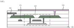
图8B为图8A中的显示面板沿C-C’方向的剖视图;Figure 8B is a cross-sectional view of the display panel in Figure 8A along the direction C-C';
图9A为根据一些实施例的显示面板的又一种结构图;FIG. 9A is another structural diagram of a display panel according to some embodiments;
图9B为根据一些实施例的第一图案层的一种结构图;Fig. 9B is a structural diagram of a first pattern layer according to some embodiments;
图9C为根据一些实施例的第二图案层的一种结构图;Fig. 9C is a structure diagram of a second pattern layer according to some embodiments;
图9D为根据一些实施例的第三图案层的一种结构图;Fig. 9D is a structure diagram of a third pattern layer according to some embodiments;
图9E为根据一些实施例的第四图案层的一种结构图;Fig. 9E is a structure diagram of a fourth pattern layer according to some embodiments;
图10为根据一些实施例的显示面板的又一种结构图;Fig. 10 is another structural diagram of a display panel according to some embodiments;
图11为根据一些实施例的第一显示区中的发光器件的一种分布图;Figure 11 is a distribution diagram of light emitting devices in the first display area according to some embodiments;
图12为根据一些实施例的显示面板的又一种结构图;Fig. 12 is another structural diagram of a display panel according to some embodiments;
图13为根据一些实施例的显示面板的又一种结构图;Fig. 13 is another structural diagram of a display panel according to some embodiments;
图14为根据一些实施例的用于驱动第一像素电路的一种信号时序图;FIG. 14 is a signal timing diagram for driving a first pixel circuit according to some embodiments;
图15为根据一些实施例的显示面板的又一种结构图;Fig. 15 is another structural diagram of a display panel according to some embodiments;
图16为根据一些实施例的显示面板的又一种结构图;Fig. 16 is another structural diagram of a display panel according to some embodiments;
图17为根据一些实施例的显示面板的又一种结构图;Fig. 17 is another structural diagram of a display panel according to some embodiments;
图18为根据一些实施例的显示面板的又一种结构图;Fig. 18 is another structural diagram of a display panel according to some embodiments;
图19为根据一些实施例的显示装置的一种结构图;Fig. 19 is a structural diagram of a display device according to some embodiments;
图20为根据一些实施例的用于驱动显示面板的一种信号时序图;FIG. 20 is a signal timing diagram for driving a display panel according to some embodiments;
图21为根据一些实施例的用于驱动显示面板的另一种信号时序图。FIG. 21 is another signal timing diagram for driving a display panel according to some embodiments.
具体实施方式Detailed ways
下面将结合附图,对本公开一些实施例中的技术方案进行清楚、完整地描述,显然,所描述的实施例仅仅是本公开一部分实施例,而不是全部的实施例。基于本公开所提供的实施例,本领域普通技术人员所获得的所有其他实施例,都属于本公开保护的范围。The technical solutions in some embodiments of the present disclosure will be clearly and completely described below in conjunction with the accompanying drawings. Apparently, the described embodiments are only some of the embodiments of the present disclosure, not all of them. All other embodiments obtained by persons of ordinary skill in the art based on the embodiments provided in the present disclosure belong to the protection scope of the present disclosure.
除非上下文另有要求,否则,在整个说明书和权利要求书中,术语“包括(comprise)”及其其他形式例如第三人称单数形式“包括(comprises)”和现在分词形式“包括(comprising)”被解释为开放、包含的意思,即为“包含,但不限于”。在说明书的描述中,术语“一个实施例(one embodiment)”、“一些实施例(some embodiments)”、“示例性实施例(exemplary embodiments)”、“示例(example)”、“特定示例(specific example)”或“一些示例(some examples)”等旨在表明与该实施例或示例相关的特定特征、结构、材料或特性包括在本公开的至少一个实施例或示例中。上述术语的示意性表示不一定是指同一实施例或示例。此外,所述的特定特征、结构、材料或特点可以以任何适当方式包括在任何一个或多个实施例或示例中。Throughout the specification and claims, unless the context requires otherwise, the term "comprise" and other forms such as the third person singular "comprises" and the present participle "comprising" are used Interpreted as the meaning of openness and inclusion, that is, "including, but not limited to". In the description of the specification, the terms "one embodiment", "some embodiments", "exemplary embodiments", "example", "specific example" example)" or "some examples" and the like are intended to indicate that a specific feature, structure, material, or characteristic related to the embodiment or example is included in at least one embodiment or example of the present disclosure. Schematic representations of the above terms are not necessarily referring to the same embodiment or example. Furthermore, the particular features, structures, materials or characteristics described may be included in any suitable manner in any one or more embodiments or examples.
以下,术语“第一”、“第二”仅用于描述目的,而不能理解为指示或暗示相对重要性或者隐含指明所指示的技术特征的数量。由此,限定有“第一”、“第二”的特征可以明示或者隐含地包括一个或者更多个该特征。在本公开实施例的描述中,除非另有说明,“多个”的含义是两个或两个以上。Hereinafter, the terms "first" and "second" are used for descriptive purposes only, and cannot be understood as indicating or implying relative importance or implicitly specifying the quantity of indicated technical features. Thus, a feature defined as "first" and "second" may explicitly or implicitly include one or more of these features. In the description of the embodiments of the present disclosure, unless otherwise specified, "plurality" means two or more.
在描述一些实施例时,可能使用了“耦接”和“连接”及其衍伸的表达。例如,描述一些实施例时可能使用了术语“连接”以表明两个或两个以上部件彼此间有直接物理接触或电接触。又如,描述一些实施例时可能使用了术语“耦接”以表明两个或两个以上部件有直接物理接触或电接触。然而,术语“耦接”或“通信耦合(communicatively coupled)”也可能指两个或两个以上部件彼此间并无直接接触,但仍彼此协作或相互作用。这里所公开的实施例并不必然限制于本文内容。In describing some embodiments, the expressions "coupled" and "connected" and their derivatives may be used. For example, the term "connected" may be used in describing some embodiments to indicate that two or more elements are in direct physical or electrical contact with each other. As another example, the term "coupled" may be used when describing some embodiments to indicate that two or more elements are in direct physical or electrical contact. However, the terms "coupled" or "communicatively coupled" may also mean that two or more elements are not in direct contact with each other, but yet still co-operate or interact with each other. The embodiments disclosed herein are not necessarily limited by the context herein.
本文中“适用于”或“被配置为”的使用意味着开放和包容性的语言,其不排除适用于或被配置为执行额外任务或步骤的设备。The use of "suitable for" or "configured to" herein means open and inclusive language that does not exclude devices that are suitable for or configured to perform additional tasks or steps.
如本文所使用的那样,“约”或“近似”包括所阐述的值以及处于特定值的可接受偏差范围内的平均值,其中所述可接受偏差范围如由本领域普通技术人员考虑到正在讨论的测量以及与特定量的测量相关的误差(即,测量系统的局限性)所确定。As used herein, "about" or "approximately" includes the stated value as well as averages within acceptable deviations from the specified value as considered by one of ordinary skill in the art in question Determined by the measurement of a given quantity and the errors associated with the measurement of a particular quantity (ie, limitations of the measurement system).
“上/上方”、“下/下方”、“行/行方向”以及“列/列方向”等指示的方位或位置关系的术语为基于附图所示的方位或位置关系,仅是为了便于说明本公开的技术方案的简化描述,而不是指示或暗示所指的装置或元件必须具有特定的方位、以特定的方位构造和操作,因此不能理解为对本公开的限制。例如,在某些情况下,涉及“行方向”的实施例可以在“列方向”的情况下实施等等,相反亦如此。将本公开所述方案进行90°旋转或镜像后亦属本公开要求保护的权利范畴。Terms indicating orientation or positional relationship such as "upper/above", "lower/below", "row/row direction" and "column/column direction" are based on the orientation or positional relationship shown in the drawings and are for convenience only A simplified description illustrating the technical solutions of the present disclosure does not indicate or imply that the referred device or element must have a specific orientation, be constructed and operated in a specific orientation, and thus should not be construed as limiting the present disclosure. For example, in some cases, an embodiment referring to a "row direction" may be implemented with respect to a "column direction" and so on, and vice versa. Rotating or mirroring the solution described in the present disclosure by 90° also falls within the scope of rights claimed in the present disclosure.
本文参照作为理想化示例性附图的剖视图和/或平面图描述了示例性实施方式。在附图中,为了清楚,放大了层和区域的厚度。因此,可设想到由于例如制造技术和/或公差引起的相对于附图的形状的变动。因此,示例性实施方式不应解释为局限于本文示出的区域的形状,而是包括因例如制造而引起的形状偏差。例如,示为矩形的蚀刻区域通常将具有弯曲的特征。因此,附图中所示的区域本质上是示意性的,且它们的形状并非旨在示出设备的区域的实际形状,并且并非旨在限制示例性实施方式的范围。Exemplary embodiments are described herein with reference to cross-sectional and/or plan views that are idealized exemplary drawings. In the drawings, the thickness of layers and regions are exaggerated for clarity. Accordingly, variations in shape from the drawings as a result, for example, of manufacturing techniques and/or tolerances are contemplated. Thus, example embodiments should not be construed as limited to the shapes of regions illustrated herein but are to include deviations in shapes that result, for example, from manufacturing. For example, an etched region illustrated as a rectangle will, typically, have curved features. Thus, the regions illustrated in the figures are schematic in nature and their shapes are not intended to illustrate the actual shape of a region of a device and are not intended to limit the scope of example embodiments.
本公开的实施例提供一种显示面板,示例性地,显示面板可以为发光二极管(Light Emitting Diode,LED)显示面板,或有机发光二极管(Organic Light EmittingDiode,OLED)显示面板。An embodiment of the present disclosure provides a display panel. Exemplarily, the display panel may be a light emitting diode (Light Emitting Diode, LED) display panel, or an organic light emitting diode (Organic Light Emitting Diode, OLED) display panel.
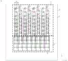
如图1和图2所示,显示面板100具有第一显示区A1、第二显示区A2、第一周边区S1和第二周边区S2。示例性地,第二显示区A2可以位于第一显示区A1的至少一侧,例如,第二显示区A2可以围绕第一显示区A1;或者,在第一显示区A1为四边形的情况下,第二显示区A2可以位于第一显示区A1三个连续分布的边沿外侧。如图2所示,第一周边区S1位于第一显示区A1外,第二周边区S2位于第二显示区A2外。例如,第一周边区S1位于第一显示区A1外至少一侧。例如,第二周边区S2位于第二显示区A2外至少一侧。例如,第一周边区S1可以位于第一显示区A1和第二显示区A2之间。又例如,第一周边区S1可以与第二周边区S2有交叠,例如,第一周边区S1可以位于第二周边区S2内。As shown in FIG. 1 and FIG. 2 , the
需要说明的是,本公开的实施例对第一显示区A1和第二显示区A2的形状不作限定,可以根据实际情况进行设置。例如,第一显示区A1和第二显示区A2的形状均为矩形(或者圆角矩形),此时,第二显示区A2的一侧边沿可以具有内凹部分(内凹方向为显示面板100的边沿指向中心的方向),第一显示区A1位于凹陷的区域内。示例性地,第一显示区域A1的面积小于或等于第二区域A2的面积。It should be noted that the embodiments of the present disclosure do not limit the shapes of the first display area A1 and the second display area A2, which can be set according to actual conditions. For example, the shapes of the first display area A1 and the second display area A2 are both rectangles (or rectangles with rounded corners). the edge of which points to the direction of the center), the first display area A1 is located in the recessed area. Exemplarily, the area of the first display area A1 is smaller than or equal to the area of the second area A2.
一些实施例中,如图1所示,通过将传感器300(例如摄像头或光线感应器等)设置于显示面板100中第一显示区A1的下方,可以提高屏占比。并且,为了使设置于显示面板100下方的传感器实现感应功能,传感器所在区域(第一显示区A1)的透过率相对较大,也即,第一显示区A1的透光率大于第二显示区A2的透光率。In some embodiments, as shown in FIG. 1 , by disposing the sensor 300 (such as a camera or a light sensor, etc.) under the first display area A1 of the
相关技术中,第一显示区A1和第二显示区A2中均设置有像素,第一显示区A1的像素的设置密度小于第二显示区A2的像素的设置密度,使得第一显示区A1的分辨率(例如200PPI(Pixels Per Inch))小于第一显示区A2的分辨率(例如400PPI)。这样,可以通过降低第一显示区A1的分辨率,来提高第一显示区A1的透过率,但会导致在第一显示区A1显示的画面的画质较低,从而降低了显示效果。In the related art, both the first display area A1 and the second display area A2 are provided with pixels, and the arrangement density of the pixels in the first display area A1 is smaller than the arrangement density of the pixels in the second display area A2, so that the arrangement density of the pixels in the first display area A1 The resolution (for example, 200PPI (Pixels Per Inch)) is smaller than the resolution of the first display area A2 (for example, 400PPI). In this way, the transmittance of the first display area A1 can be increased by reducing the resolution of the first display area A1, but the picture quality displayed in the first display area A1 will be lower, thereby reducing the display effect.
如图2所示,本公开的实施例提供的显示面板100包括衬底101、多个发光器件110和多个第一像素电路120。多个发光器件110设置于衬底101上且位于第一显示区A1内。多个第一像素电路120设置于衬底101上且位于第一周边区S1内。As shown in FIG. 2 , a
示例性地,衬底101可以包括玻璃等刚性衬底(或称为硬质衬底),或者PI(Polyimide,聚酰亚胺)等柔性衬底;还可以包括设置在刚性衬底或柔性衬底上的缓冲层等薄膜。发光器件110可以包括LED或者OLED。Exemplarily, the
需要说明的是,本公开的实施例对第一像素电路120的具体结构不作限定,可以根据实际情况进行设计。示例性地,第一像素电路120由薄膜晶体管(Thin Film Transistor,简称TFT)、电容(Capacitance,简称C)等电子器件组成。例如,第一像素电路120可以是由两个薄膜晶体管(一个开关晶体管和一个驱动晶体管)和一个电容构成的2T1C结构的像素电路;当然,第一像素电路120还可以是由两个以上的薄膜晶体管(多个开关晶体管和一个驱动晶体管)和至少一个电容构成的像素电路,例如参考图5,第一像素电路120可以包括存储电容Cst和七个晶体管(六个开关晶体管(M1、M2、M3、M5、M6、M7和一个驱动晶体管M4)构成的7T1C像素电路。It should be noted that, the embodiments of the present disclosure do not limit the specific structure of the
并且,在发光器件110为OLED的情况下,发光器件110包括阴极和阳极,以及位于阴极和阳极之间的发光功能层。其中,发光功能层例如可以包括有机发光层、位于有机发光层和阳极之间的空穴传输层、位于有机发光层和阴极之间的电子传输层。当然,根据需要在一些实施例中,还可以在空穴传输层和阳极之间设置空穴注入层,可以在电子传输层和阴极之间设置电子注入层。需要说明的是,为了方便描述,本公开的实施例均以发光器件110的阳极来示意发光器件110,实际发光器件110的结构和阳极的结构并不相同。Moreover, when the
可以理解的是,发光器件110与多个第一像素电路120不在同一区域内,多个第一像素电路120可以位于第一显示区A1外至少一侧,例如位于第二显示区A2与第一显示区A1之间的间隔区域,使得多个第一像素电路120不会对第一显示区A1的光线进行遮挡,可以提高第一显示区A1的透过率。在此情况下,可以提高第一显示区A1的像素的设置密度,即提高第一显示区A1的分辨率(例如第一显示区A1的分辨率可以从200PPI提升至400PPI),使得第一显示区A1的分辨率与第二显示区A2的分辨率相等。It can be understood that the
并且,在第一显示区A1的分辨率与第二显示区A2的分辨率相等的情况下,第一显示区A1所包含的发光器件的设置密度与第二显示区A2所包含的发光器件的设置密度相等,第一显示区A1的像素电路(第一像素电路120)的设置密度与第二显示区A2的像素电路(如下文中的第二像素电路170)相等。因此,相比于第一像素电路120设置在第一显示区A1内,本公开的实施例可以避免多个第一像素电路120对光线的遮挡,提高了第一显示区A1的透过率,保证显示面板100可以实现屏下传感(例如屏下摄像)。Moreover, when the resolution of the first display area A1 is equal to the resolution of the second display area A2, the arrangement density of the light emitting devices included in the first display area A1 is the same as that of the light emitting devices included in the second display area A2. The arrangement densities are equal, and the arrangement density of the pixel circuits (first pixel circuits 120 ) in the first display area A1 is equal to that of the pixel circuits in the second display area A2 (such as the
示例性地,第一显示区A1内发光器件的平均单位发光面积可以等于第二显示区A2内发光器件的平均单位发光面积可以相等。或者,第一显示区A1内发光器件的平均单位发光面积可以小于第二显示区A2内发光器件的平均单位发光面积,以避免屏下摄像头在拍照的过程中,发光器件对光线的遮挡,出现衍射的问题。Exemplarily, the average unit light emitting area of the light emitting devices in the first display area A1 may be equal to the average unit light emitting area of the light emitting devices in the second display area A2. Alternatively, the average unit light-emitting area of the light-emitting devices in the first display area A1 may be smaller than the average unit light-emitting area of the light-emitting devices in the second display area A2, so as to prevent the light-emitting devices from blocking light when the camera under the screen takes pictures. Diffraction problem.
如图3所示,显示面板100还包括选通电路130。选通电路130设置于衬底101上。选通电路130与多个发光器件110和多个第一像素电路120耦接。选通电路130被配置为将每个第一像素电路120与至少两个发光器件110分时导通,以驱动与第一像素电路120相导通的发光器件110发光。As shown in FIG. 3 , the
可以理解的是,一个第一像素电路120通过选通电路130与至少两个发光器件110耦接,也就是说,一个第一像素电路120可以分别通过选通电路130分时驱动至少两个发光器件110工作(发光)。例如,在一个第一像素电路120与多个发光器件110耦接的情况下,第一像素电路120通过选通电路130,每一次导通一个发光器件110,或者,每一次导通至少两个发光器件110。It can be understood that one
在此情况下,相比于每个第一像素电路120与每个发光器件110一一对应耦接的情况,本公开的实施例中的每个第一像素电路120通过选通电路130与至少两个发光器件110耦接,可以减少第一像素电路120的数量,减少了第一像素电路120所在区域的面积,降低了第一周边区S1的面积,便于实现窄边框。并且,在第一像素电路120位于第一显示区A1和第二显示区A2之间的情况下,可以降低第一显示区A1和第二显示区A2之间的第一周边区S1的面积,从而提高显示面板100的显示效果。In this case, compared with the case where each
因此,本公开的实施例提供的显示面板100,多个发光器件110位于第一显示区A1内,多个第一像素电路120位于第一周边区S1内,并且通过选通电路130将每个第一像素电路120与至少两个发光器件110分时导通,以驱动与第一像素电路120相导通的发光器件110发光。在此情况下,由于第一显示区A1中不设置多个第一像素电路120,使得多个第一像素电路120不会对第一显示区A1的光线进行遮挡,可以提高第一显示区A1的透过率,并提高第一显示区A1的分辨率,并使得第一显示区A1和第二显示区A2达到相同的分辨率,从而提高显示面板100的显示效果。并且,每个第一像素电路120通过选通电路130与至少两个发光器件110耦接,可以减少第一像素电路120的数量,减少了第一像素电路120所在区域的面积,便于显示面板100实现窄边框。Therefore, in the
在一些实施例中,如图4所示,选通电路130包括多条控制信号线131、多条驱动信号线132和多个晶体管133。多条驱动信号线132与多个第一像素电路120耦接。每个晶体管133的控制极与控制信号线131耦接,晶体管133的第一极与驱动信号线132耦接,晶体管133的第二极与发光器件110耦接。In some embodiments, as shown in FIG. 4 , the
其中,多条控制信号线131和多条驱动信号线132有交叉,多条控制信号线131相比于多条驱动信号线132靠近衬底101。晶体管133的第二极与发光器件110的阳极耦接。Wherein, the plurality of
示例性地,驱动信号线132呈透明。这样,由于驱动信号线132与第一显示区A1有交叠,因此,可以避免影响第一显示区A1的透过率。示例性地,控制信号线131的材料可以与晶体管133的控制极的材料相同,控制信号线131和晶体管133的控制极可以同步形成,控制信号线131的材料可以包括金属,例如Mo(钼)等;或者,控制信号线131也可以呈透明,例如,控制信号线131的材料和驱动信号线132的材料均可以包括透明导电材料,例如ITO(氧化铟锡)等。Exemplarily, the driving
需要说明的是,晶体管133可以为薄膜晶体管、场效应晶体管(Field EffectTransistor,FET)或其他特性相同的开关器件,本公开的实施例对此并不设限。并且,文中所描述的各晶体管的控制极为晶体管的栅极,第一极为晶体管的源极和漏极中一者,第二极为晶体管的源极和漏极中另一者。由于晶体管的源极、漏极在结构上可以是对称的,所以其源极、漏极在结构上可以是没有区别的,也就是说,本公开的实施例中的晶体管的第一极和第二极在结构上可以是没有区别的。示例性的,在晶体管为P型晶体管的情况下,晶体管的第一极为源极,第二极为漏极;示例性的,在晶体管为N型晶体管的情况下,晶体管的第一极为漏极,第二极为源极。It should be noted that the
可以理解的是,选通电路130通过多条控制信号线131,向与控制信号线131耦接的晶体管133传输控制信号,以使晶体管133导通,与同一控制信号线131耦接的各晶体管133同时被导通,与不同控制信号线131耦接的各晶体管133分时被导通。在晶体管133导通的情况下,与该晶体管133耦接的第一像素电路120通过驱动信号线132,向与该晶体管133耦接的发光器件110传输驱动信号,以驱动发光器件110工作。It can be understood that the
其中,显示面板100的分辨率可以达到全高清(Full High Definition,FHD)的分辨率,即,显示面板100可以显示全高清图像。其中,对于达到全高清分辨率的显示面板,参考图4,一个子像素区域P的宽度WP(例如参考图4中的水平方向X的尺寸)约为32μm,高度HP(例如参考图4中的竖直方向Y的尺寸)约为64μm。需要说明的是,为了方便表示,图中以发光器件110所在位置代表子像素区域P所在位置,但实际两者不一定相等。Wherein, the resolution of the
示例性地,在如图6所示的显示面板100’中,一个发光器件110’通过一条驱动信号线132’与一个第一像素电路120’耦接。参考图6,驱动信号线132’的宽度WL(例如参考图6中的水平方向X的尺寸)约为4μm。这样,对于全高清的显示面板,在一个子像素区域,若驱动信号线132’为单层设置,则沿水平方向X,可以设置8条(32μm/4μm=8)驱动信号线132’,即,在竖直方向Y上的一列子像素区域可以包括8个子像素区域(即一列发光器件可以包括8个发光器件),此时,第一显示区A1在竖直方向Y上的尺寸为8×64μm=0.512mm;若驱动信号线132’为双层设置,则可以设置16条驱动信号线132’,即,沿竖直方向Y,一列子像素区域可以包括16个子像素区域(即一列发光器件可以包括16个发光器件),此时,第一显示区A1在竖直方向Y上的尺寸为16×64μm=1.024mm;若驱动信号线132’为三层设置,则可以设置24条驱动信号线132’(例如,第一显示区A1的驱动信号线132’可以双侧走线),即,沿竖直方向Y,一列子像素区域可以包括24个子像素区域(即一列发光器件可以包括24个发光器件),此时,第一显示区A1在竖直方向Y上的尺寸为24×64μm=1.536mm。Exemplarily, in the display panel 100' as shown in FIG. 6, one light emitting device 110' is coupled to one first pixel circuit 120' through one driving signal line 132'. Referring to FIG. 6 , the width WL of the driving
在此情况下,由于屏下摄像所采用的摄像头的孔径大于3mm,因此,至少需要设置三层驱动信号线132’,才能使得第一显示区A1有足够的空间设置摄像头。这样,在工艺上采用掩膜板(mask)在衬底101上形成一具有过孔的平坦层(PLN),在该平坦层上形成透明导电薄膜,采用掩膜板对透明导电薄膜进行图案化,形成第一层的驱动信号线132’,在第一层的驱动信号线132’上采用掩膜板形成另一具有过孔的平坦层,并在其上形成透明导电薄膜,采用掩膜板对透明导电薄膜进行图案化,形成第二层连的驱动信号线132’,在第二层的驱动信号线132’上采用掩膜板形成又一具有过孔的平坦层,在其上形成透明导电薄膜,采用掩膜板对透明导电薄膜进行图案化,形成第三层的驱动信号线132’,这样形成三层驱动信号线132’的过程需要六张掩膜板对六个膜层进行图案化。因此,显示面板100的制备工艺复杂,生产成本较大,容易导致显示面板的生产能力损失较大。In this case, since the aperture of the camera used for the under-screen camera is greater than 3mm, at least three layers of driving signal lines 132' need to be provided so that the first display area A1 has enough space for the camera. In this way, in the process, a mask plate (mask) is used to form a flat layer (PLN) with via holes on the
可以理解的是,由于显示面板100中的第一像素电路120通过选通电路130可以分时与至少两个发光器件110形成导电通路,因此,一个第一像素电路120可以通过一条驱动信号线132与至少两个晶体管133耦接,即,一个第一像素电路120通过一条驱动信号线12与至少两个发光器件110耦接,该至少两个晶体管133通过不同的控制信号线131分时导通,与第一像素电路120形成导电通路,使得第一像素电路120实现对至少两个发光器件110的分时驱动。因此,相比于一个发光器件通过一条驱动信号线与一个第一像素电路耦接的情况,减少了驱动信号线132的数量,使得第一显示区A1有较大的空间对多条驱动信号线132进行布线,避免因对多条驱动信号线132进行多层设置,而导致工艺复杂,生产成本较大,显示面板的生产能力损失较大。It can be understood that, since the
在一些实施例中,多条驱动信号线132同层设置,即,多条驱动信号线132由同一膜层构图形成,从而简化了生产工艺,降低了生产成本。In some embodiments, the multiple
在一些实施例中,如图4所示,多个发光器件110分为第一发光器件列L1和第二发光器件列L2,第一发光器件列L1与第二发光器件列L2依次间隔设置。示例性地,沿图4中的水平方向X,相邻两列第一发光器件列L1之间设置有一列第二发光器件列L2。示例性地,相邻的第一发光器件列L1和第二发光器件列L2是错位的,即,沿垂直于发光器件110排列的列方向(例如参考图11中的水平方向X),第一发光器件列L1中的每行发光器件110,与第二发光器件列L2中对应行的发光器件110错位排列。例如,参考图11,在相邻两列第一发光器件列L1中,一列第一发光器件列L1中的相邻两行发光器件110和另一列第一发光器件列L1中的对应两行第一发光器件110,四个第一发光器件110的几何中心依次连线构成四边形Q,此时,这两列第一发光器件列L1之间的一列第二发光器件列L1中的一个发光器件110的几何中心与该四边形Q中两条对角线的交点重合。In some embodiments, as shown in FIG. 4 , the plurality of light emitting
第一发光器件列L1中的一行发光器件所耦接的晶体管133和第二发光器件列L2中对应行发光器件110所耦接的晶体管,与同一条控制信号线111耦接。在每列发光器件中,相邻两行发光器件110所耦接的两个晶体管133通过不同的驱动信号线132与不同的第一像素电路120耦接。The
其中,第一发光器件列L1的延伸方向与第二发光器件列L2的延伸方向相同,且沿垂直于发光器件的列方向,第一发光器件列L1与第二发光器件列L2依次间隔设置,即,一个第二发光器件列位于相邻两个第一发光器件列之间。Wherein, the extension direction of the first light-emitting device column L1 is the same as the extension direction of the second light-emitting device column L2, and along the column direction perpendicular to the light-emitting device, the first light-emitting device column L1 and the second light-emitting device column L2 are sequentially arranged at intervals, That is, one second light emitting device column is located between two adjacent first light emitting device columns.
需要说明的是,上述的第二发光器件列L2中对应行发光器件110指的是在第二发光器件列L2中与第一发光器件列L1中的一行发光器件行数相同的发光器件,例如对于第一发光器件列L1中的第一行发光器件,第二发光器件列L2中对应行的发光器件为第二发光器件列L2中的第一行发光器件。每列发光器件中的相同行的发光器件构成上述的一行发光器件,例如,各第一发光器件列L1中的第一行发光器件(即第一个发光器件)和各第二发光器件列L2中的对应行发光器件(即第一行发光器件)构成一行发光器件(即第一行发光器件)。It should be noted that the
可以理解的是,一行发光器件所耦接的晶体管133通过一条控制信号线131控制,这样,一行发光器件可以与各自所耦接的第一像素电路120形成导电通路,在一行发光器件各自所耦接的第一像素电路120输出驱动信号的情况下,一行发光器件可以同步被驱动发光,在此情况下,第一显示区A1中的发光器件110可以被逐行点亮。并且,每列发光器件中的相邻两行(相邻两个)发光器件110通过不同的第一像素电路120驱动发光,根据实际发光情况,可以对不同的第一像素电路120的驱动方式进行选择,例如,相邻两行发光器件所耦接的不同的第一像素电路,可以驱动该相邻两行发光器件同时发光;或者,相邻两行发光器件所耦接的不同的第一像素电路,可以驱动该相邻两行发光器件分时发光。It can be understood that the
在一些实施例中,如图4所示,每列发光器件110所耦接的晶体管133与每列第一像素电路120耦接。一列第一像素电路120包括N个第一像素电路120,N为大于1的整数。在一列发光器件110中的每N行连续分布的发光器件110所耦接的晶体管133,分别与一列第一像素电路中的N个第一像素电路依次耦接。In some embodiments, as shown in FIG. 4 , the
需要说明的是,一列第一像素电路由与一列发光器件耦接的第一像素电路120构成,且与同一行发光器件耦接的各第一像素电路120构成一行第一像素电路。示例性地,多个第一像素电路120呈阵列排布,沿图4中竖直方向Y排列的一排第一像素电路为一列第一像素电路,沿图4中水平方向X排列的一排第一像素电路为一行第一像素电路。It should be noted that a column of first pixel circuits is composed of
并且,可以根据实际情况对每列第一像素电路中的第一像素电路的数量进行设计,在此不作限定,例如,如图4所示,N可以为2,即一列第一像素电路包括两个第一像素电路120;或者,如图7所示,N可以为4,即一列第一像素电路包括四个第一像素电路120。其中,一列第一像素电路中的第一像素电路120的数量,小于与该列第一像素电路耦接的一列发光器件中的发光器件110的数量。Moreover, the number of first pixel circuits in each column of first pixel circuits can be designed according to actual conditions, and is not limited here. For example, as shown in FIG. 4, N can be 2, that is, a column of first pixel circuits includes two or, as shown in FIG. 7 , N may be 4, that is, a column of first pixel circuits includes four
示例性地,在一列第一像素电路包括两个第一像素电路120的情况下,参考图4,在与该列第一像素电路120耦接的一列发光器件110中,奇数行发光器件所耦接的晶体管133与两个第一像素电路120中的一个第一像素电路120耦接,偶数行发光器件所耦接的晶体管133与两个第一像素电路120中的另一个第一像素电路120耦接。Exemplarily, in the case that a column of first pixel circuits includes two
例如,如图4所示,一列发光器件中的第一行发光器件所耦接的晶体管与两个第一像素电路120中的第一行第一像素电路耦接,一列发光器件中的第二行发光器件所耦接的晶体管与两个第一像素电路120中的第二行第一像素电路耦接,一列发光器件中的第三行发光器件所耦接的晶体管与两个第一像素电路120中的第一行第一像素电路耦接,一列发光器件中的第四行发光器件所耦接的晶体管与两个第一像素电路120中的第二行第一像素电路耦接,依次类推。For example, as shown in FIG. 4 , the transistors coupled to the first row of light-emitting devices in a column of light-emitting devices are coupled to the first pixel circuits in the first row of two
可以理解的是,两个第一像素电路120交替工作,以分时驱动各发光器件110,并且,在一列发光器件中,当一个发光器件110被一个第一像素电路120驱动工作时,其余发光器件110均不工作。例如,在第一行第一像素电路驱动第一行发光器件工作时,第二行第一像素电路不驱动与其耦接的发光器件工作,与第一行第一像素电路耦接的除第一行发光器件以外的其他发光器件也不工作,且除第一行发光器件以外的其他发光器件所耦接的晶体管均未导通;在第二行第一像素电路驱动第二行发光器件工作时,第一行第一像素电路不驱动与其耦接的发光器件工作,与第二行第一像素电路耦接的除第二行发光器件以外的其他发光器件也不工作,且除第二行发光器件以外的其他发光器件所耦接的晶体管均未导通;在第一行第一像素电路驱动第三行发光器件工作时,第二行第一像素电路不驱动与其耦接的发光器件工作,与第一行第一像素电路耦接的除第三行发光器件以外的其他发光器件也不工作,且除第三行发光器件以外的其他发光器件所耦接的晶体管均未导通。It can be understood that the two
示例性地,在一列第一像素电路包括四个第一像素电路120的情况下,参考图7,在一列发光器件110中的每四行连续分布的发光器件110所耦接的晶体管133,分别与一列第一像素电路中的四个第一像素电路依次耦接,四个第一像素电路依次周期性工作。例如,如图7所示,第一行发光器件与第一行第一像素电路耦接,第二行发光器件与第二行第一像素电路耦接,第三行发光器件与第三行第一像素电路耦接,第四行发光器件与第四行第一像素电路耦接,第五行发器件与第一行第一像素电路耦接,第六行发光器件与第二行第一像素电路耦接,第七行发光器件与第三行第一像素电路耦接,第八行发光器件与第八行第一像素电路耦接,以此类推。在此情况下,第一行至第四行第一像素电路依次驱动第一行至第四行发光器件,在第四行第一像素电路驱动第四行发光器件之后,第一行第一像素电路开始驱动第五行发光器件,即,第一行至第四行第一像素电路依次驱动第五行至第八行发光器件,以此类推。Exemplarily, in the case that a column of first pixel circuits includes four
在一些实施例中,参考图4和图7,耦接同一第一像素电路的晶体管与同一条驱动信号线耦接。在此情况下,至少两个发光器件110通过一条驱动信号线132与一个第一像素电路120耦接,这样可以减少驱动信号线132的数量,从而简化显示面板100的走线设计。In some embodiments, referring to FIG. 4 and FIG. 7 , transistors coupled to the same first pixel circuit are coupled to the same driving signal line. In this case, at least two light emitting
示例性地,在一列第一像素电路120包括两个第一像素电路120的情况下,在与该列第一像素电路120耦接的一列发光器件110中,奇数行发光器件所耦接的晶体管133通过一条驱动信号线132与两个第一像素电路120中的一个第一像素电路120耦接,偶数行发光器件所耦接的晶体管133通过一条驱动信号线132与两个第一像素电路120中的另一个第一像素电路120耦接。在此情况下,在一列发光器件所在位置处可以设置两条驱动信号线132,以使得两个第一像素电路120可以分时驱动一列发光器件中的所有发光器件,例如,在一列发光器件包括八个发光器件的情况下,相比于八个发光器件分别通过八条驱动信号线与一列八个第一像素电路耦接的情况,本公开的实施例可以将八个发光器件通过两条驱动信号线分别与一列两个第一像素电路耦接,使得一列发光器件所耦接的驱动信号线由八条减少至两条。因此,减少了驱动信号线132的数量,避免因驱动信号线132数量过多,需要在第一显示区A1内进行多层布设驱动信号线132,而导致工艺复杂,生产成本增加。Exemplarily, in the case that a column of
在一些实施例中,如图8A和图8B所示,多个晶体管133位于多个发光器件110靠近衬底101的一侧。至少一个晶体管133在衬底101上的正投影与发光器件110在衬底101上的正投影有交叠。例如,参考图8A,发光器件110在衬底101上的正投影可以覆盖一个晶体管133在衬底101上的正投影。在此情况下,发光器件110可以对至少一个晶体管133进行遮挡,从而提高了第一显示区A1的开口率。In some embodiments, as shown in FIG. 8A and FIG. 8B , the plurality of
其中,多条驱动信号线132位于多个晶体管133与多个发光器件110之间。示例性地,驱动信号线132通过贯通位于驱动信号线132和晶体管133之间膜层的过孔,与晶体管133耦接。发光器件110通过贯通位于发光器件110和晶体管133之间膜层的过孔,与晶体管133耦接。Wherein, the plurality of driving
需要说明的是,为了简化描述,图8A和图8B仅示意出了发光器件110的阳极。It should be noted that, in order to simplify the description, FIG. 8A and FIG. 8B only illustrate the anode of the
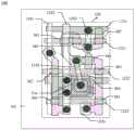
示例性地,参考图9A至图9E,显示面板100还包括在衬底101上依次层叠的第一图案层121、第二图案层122、第三图案层123和第四图案层124。根据各个图案层的导电图案可以得到第一像素电路120的版图。第一像素电路和第二像素电路的组成结构相同。Exemplarily, referring to FIG. 9A to FIG. 9E , the
其中,第一图案层121包括像素电路中各个晶体管的半导体图案,例如该半导体图案的部分可以作为晶体管的有源层图案,部分可以作为晶体管的源-漏极图案;第二图案层122包括用于传输复位信号N-1的导电图案1221、用于传输栅极信号N的导电图案1222、存储电容Cst的第一极板Csta和用于传输发光信号EM的导电图案1223,导电图案1221、导电图案1222和导电图案1223分别作为像素电路中各晶体管的栅极图案;第三图案层123包括用于传输初始电压Vint的导电图案1231和存储电容Cst的第二极板Cstb;第四图案层124包括用于传输数据信号Vdata的导电图案1241、用于传输电源电压ELVDD的导电图案1242和多个连接图案1243。Wherein, the
在此情况下,例如,控制信号线131可以位于第二图案层122中,即,控制信号线131可以与导电图案1221、导电图案1222和导电图案1223同层设置。例如,发光器件110相比于第四图案层124远离衬底101。例如,晶体管133的栅极可以位于第二图案层中;晶体管133的半导体图案可以位于第一图案层中;晶体管133的源极和漏极可以位于第四图案层中,或者,由其半导体图案的部分充当。例如,驱动信号线132位于发光器件110和第一像素电路120之间,驱动信号线132所在膜层相比于第四图案层124远离衬底101。例如,第四图案层在远离衬底的一侧设置有驱动信号线,且第四图案层和驱动信号线之间存在绝缘层,驱动信号线远离衬底的一侧设置有发光器件,且驱动信号线和发光器件之间也存在绝缘层,此时,在第二显示区内,第二像素电路和其所耦接的发光器件之间可以有至少两层绝缘层。In this case, for example, the
示例性地,参考图4,每个发光器件110在衬底101上的正投影与每个晶体管133在衬底101上的正投影有交叠。在此情况下,每个发光器件110可以对每个晶体管133进行遮挡,从而使得第一显示区A1的开口率得到更大地提升。Exemplarily, referring to FIG. 4 , the orthographic projection of each light emitting
可以理解的是,每个晶体管133位于每个发光器件110的下方(即发光器件110靠近衬底101的一侧),晶体管133在第一显示区A1内均匀分布。相应的,多条控制信号线131在显示面板100上也均匀分布,此时,在发光器件110排列的列方向上,多条控制信号线131间隔分布,且相邻两条控制信号线131的间距近似相等。It can be understood that each
示例性地,如图10所示,与一列发光器件110耦接的多个晶体管133划分为多个晶体管组1330,每个晶体管组1330包括至少两个晶体管133。在发光器件110排列的列方向上,至少两个晶体管133所耦接的发光器件110连续分布,且相邻两个晶体管组1330之间,间隔有至少一个发光器件110。Exemplarily, as shown in FIG. 10 , a plurality of
其中,至少两个晶体管133可以在垂直于发光器件110排列的列方向依次排列,且排列成一排(即并排排列或对位排列)。例如,如图10所示,与一列发光器件110耦接的多个晶体管133中,每四个晶体管133分为一个晶体管组1330,在发光器件110排列的列方向上,相邻两个晶体管组1330之间,间隔有三个发光器件110,例如,相邻两个晶体管组1330的一组中的四个晶体管133与另一组中的四个晶体管133之间间隔有三个发光器件110。一个晶体管组1330中的四个晶体管133在垂直于发光器件110排列的列方向并排排列。Wherein, at least two
在此情况下,至少两个晶体管133可以集中分布,即至少两个晶体管133之间的距离较小,且相邻两个晶体管组1330中的至少两个晶体管133之间的距离较大,这样,可以避免经过晶体管133光发生衍射,从而可以提高屏下传感的效果。In this case, the at least two
示例性地,如图10所示,多条控制信号线131划分为多个控制信号线组1310。每个控制信号线组1310包括至少两条控制信号线131。在发光器件110排列的列方向上,至少两条控制信号线131所耦接的发光器件110连续分布,相邻两个控制信号线组1310之间,间隔有至少一个发光器件110。控制信号线组1310中的至少两条控制信号线131的间距,小于相邻两个发光器件110的间距。Exemplarily, as shown in FIG. 10 , the multiple
可以理解的是,一个晶体管组1330中的至少两个晶体管133耦接的至少两条控制信号线131可以集中分布。相邻两个晶体管组1330所耦接的控制信号线131之间,间隔有至少一个发光器件。例如,在一个晶体管组1330包括四个晶体管133的情况下,与四个晶体管133耦接的四条控制信号线131可以位于相邻两个发光器件110之间的区域内,且,相邻两个晶体管组1330所耦接的控制信号线131之间,间隔有至少三个发光器件。It can be understood that at least two
在此情况下,控制信号线组1310中的至少两条控制信号线131之间的距离较小,且一控制信号线组1310中的至少两条控制信号线131和与其相邻的另一控制信号线组1310中的至少两条控制信号线131之间的距离较大。这样,显示面板100中的至少两条控制信号线131集中分布,可以避免经过控制信号线131的光发生衍射,从而可以提高屏下传感的效果。In this case, the distance between at least two
其中,在至少两条控制信号线131和至少两个晶体管133集中分布的情况下,晶体管133和其所对应的发光器件110之间的距离较大,因此,如图10所示,晶体管133可以通过连接引线103与晶体管133对应的发光器件110耦接。示例性地,连接引线103可以呈透明,避免影响第一显示区A1的透过率。连接引线103的材料与驱动信号线132的材料相同,即,连接引线103可以与驱动信号线132由同一膜层构图形成,简化生产工序。Wherein, in the case where at least two
示例性地,如图11所示,多个发光器件110包括第一颜色发光器件111、第二颜色发光器件112和第三颜色发光器件113。第一发光器件列L1包括依次间隔排布的第一颜色发光器件111和第二颜色发光器件112,第二发光器件列L2包括间隔排布的多个第三颜色发光器件113。在垂直于发光器件110排列的列方向(例如图11中的水平方向X)上,第一发光器件列L1中的每行发光器件110,与第二发光器件列L2中对应行的发光器件110错位排列。Exemplarily, as shown in FIG. 11 , the plurality of light emitting
其中,第一颜色、第二颜色和第三颜色分别为三基色,例如,第一颜色为蓝色,第二颜色为红色,第三颜色为绿色,此时,第一发光器件列L1包括依次间隔排布的蓝色发光器件111和红色发光器件112,第二发光器件列L2包括间隔排布的多个绿色发光器件113。Wherein, the first color, the second color and the third color are respectively three primary colors. For example, the first color is blue, the second color is red, and the third color is green. At this time, the first light-emitting device column L1 includes The blue
需要说明的是,上述的错位排列指的是,在垂直于发光器件110排列的列方向(例如图11中的水平方向X)上,各列发光器件中的对应行发光器件的几何中心不完全处于一条直线上,即,沿垂直于发光器件110排列的列方向,依次连接各列发光器件中的对应行发光器件的几何中心,连线所形成的线条整体呈折线。示例性地,在相邻两个第一发光器件列L1和第二发光器件列L2中,对应行的两个发光器件的几何中心的连线与垂直于发光器件110排列的列方向相交叉。在相邻两个第一发光器件列L1中,对应行的两个发光器件的几何中心的连线与垂直于发光器件110排列的列方向相平行;在相邻两个第二发光器件列L2中,对应行的两个发光器件的几何中心的连线与垂直于发光器件110排列的列方向相平行。It should be noted that the above dislocation arrangement means that in the column direction perpendicular to the arrangement of the light emitting devices 110 (for example, the horizontal direction X in FIG. 11 ), the geometric center of the corresponding row of light emitting devices in each column of light emitting devices is incomplete. On a straight line, that is, along the column direction perpendicular to the arrangement of the
在一些实施例中,如图12所示,显示面板100还包括第一驱动电路140和第二驱动电路150。第一驱动电路140和第二驱动电路150均设置于第一周边区S1内。第一驱动电路140包括多个级联的第一移位寄存电路141,一个第一移位寄存器141与一条控制信号线131耦接。第二驱动电路150包括多个级联的第二移位寄存电路151,一个第二移位寄存电路151与一行第一像素电路120耦接。In some embodiments, as shown in FIG. 12 , the
其中,第一驱动电路140被配置为向控制信号线131提供控制信号,以使与该控制信号线131耦接的晶体管133导通,将该晶体管133所耦接的发光器件110和第一像素电路120形成导电通路。第二驱动电路150被配置为向第一像素电路120提供扫描信号,以使第一像素电路120在与其所耦接的发光器件110形成导电通路的情况下,驱动发光器件110发光。Wherein, the
可以理解的是,第一驱动电路140中的多个级联的第一移位寄存器141,分别向多条控制信号线131依次输出控制信号,以使与多条控制信号线131耦接的晶体管133逐行导通。第二驱动电路150中的多个级联的第二移位寄存电路151分别向多行第一像素电路120依次输出扫描信号,以使多行第一像素电路120逐行写入数据。It can be understood that, the plurality of cascaded
在此情况下,相比于图6所示的显示面板100’中的第一像素电路120’的数量较多,且第二驱动电路150’的数量较多的情况,图13所示的显示面板100中的第一像素电路120和第二驱动电路150的数量均较少,降低了第一周边区S1的面积,使得显示面板100便于实现窄边框。In this case, compared with the case where the number of first pixel circuits 120' in the display panel 100' shown in FIG. 6 is larger and the number of second driving circuits 150' is larger, the display shown in FIG. The numbers of the
示例性地,如图5所示,第一像素电路120中的一部分开关晶体管(例如,M1、M7)的控制极用于接收如图14所示的复位信号N-1。另一部分开关晶体管(例如,M2、M3)的控制极用于接收如图14所示的栅极信号N。又一部分开关晶体管(例如,M5、M6)的控制极用于接收如图14所示的发光信号EM。需要说明的是,图5中的第一像素电路120仅为一种示意,实际情况中的第一像素电路120的具体电路结构不限于此。Exemplarily, as shown in FIG. 5 , the control electrodes of some switch transistors (for example, M1 and M7 ) in the
在此基础上,图5所示的第一像素电路120的工作过程包括图14所示的三个阶段,第一阶段①、第二阶段②以及第三阶段③。其中,在第一阶段①,在复位信号N-1的控制下,晶体管M1和晶体管M7导通。选通电路130中的至少两个晶体管133中的待驱动的发光器件110所耦接的晶体管133在控制信号线131处接收的控制信号CT的控制下导通,初始电压Vint通过晶体管M1、晶体管M7和待驱动的发光器件110所耦接的晶体管133,分别传输至驱动晶体管M4的控制极g以及发光器件110的阳极a,以对发光器件110的阳极a以及驱动晶体管M4的控制极g进行复位。在第二阶段②,在栅极信号N的控制下,晶体管M2和晶体管M3导通,驱动晶体管M4的控制极g与第二极d耦接,该驱动晶体管M4成二极管导通状态。此时,数据信号Vdata通过该晶体管M2写入至驱动晶体管M4的第一极s,并对驱动晶体管M4的阈值电压Vth进行补偿。第三阶段③,在发光信号EM的控制下,晶体管M5和晶体管M6导通,并且,选通电路130中的至少两个晶体管133中的待驱动的发光器件110所耦接的晶体管133在控制信号线131处接收的控制信号CT的控制下导通,通过选通电路130将驱动晶体管M4、晶体管M5和晶体管M6与发光器件110形成导电通路,电源电压ELVDD与ELVSS之间的电流通路导通。驱动晶体管M4根据数据信号Vdata产生的驱动电流Isd传输至发光器件110,以分时驱动至少两个发光器件110进行发光。On this basis, the working process of the
在此情况下,如图15所示,至少一个第二驱动电路150包括三个第二驱动电路,分别为第二驱动电路150A、第二驱动电路150B和第二驱动电路150C。第二驱动电路150A通过栅线GL与第一像素电路120耦接,用于向第一像素电路120提供栅极信号N;第二驱动电路150B通过发光信号线EL与第一像素电路120耦接,用于向第一像素电路120提供发光信号EM;第二驱动电路150C通过复位信号线RL与第一像素电路120耦接,用于向第一像素电路120提供复位信号N-1。In this case, as shown in FIG. 15 , at least one
在此情况下,第二驱动电路150A包含多个级联的第二移位寄存电路151A,一行第一像素电路120中的晶体管M2和晶体管M3的控制极可以与第二驱动电路150A中的一个第二移位寄存电路151A的信号输出端耦接;第二驱动电路150B包含多个级联的第二移位寄存电路151B,一行第一像素电路120中的晶体管M5和晶体管M6的控制极可以与第二驱动电路150B中的一个第二移位寄存电路151B的信号输出端耦接;第二驱动电路150C包含多个级联的第二移位寄存电路151C,一行第一像素电路120中的晶体管M1和晶体管M7的控制极可以与第二驱动电路150C中的一个第二移位寄存电路151C的信号输出端耦接。In this case, the
或者,至少一个第二驱动电路150包括两个第二驱动电路,分别为第二驱动电路150A和第二驱动电路150B,此时,第二驱动电路150A向第一像素电路120提供栅极信号N,且该栅极信号N可以作为该第一像素电路120的上一行第一像素电路的复位信号N-1。在此情况下,一行第一像素电路120中的晶体管M2和晶体管M3的控制极,及其上一行第一像素电路120中的晶体管M2和晶体管M3的控制极,可以与第二驱动电路150A中的一个第二移位寄存电路151A的信号输出端耦接。Alternatively, at least one
需要说明的是,第一驱动电路140和第二驱动电路150可以采用领域内任何能够实现相应功能的电路或模块。在实际应用中,技术人员可以根据情况进行选择,本公开在此不作限定。It should be noted that, the
在一些实施例中,如图12所示,沿发光器件110排列的列方向(例如图12中的竖直方向Y),第一驱动电路140位于第一显示区A1外的相对两侧中靠近显示面板100边沿的一侧。在此情况下,可以减少第一显示区A1周围的边框宽度,提高显示面板100的显示效果。In some embodiments, as shown in FIG. 12 , along the column direction in which the
示例性地,多条控制信号线131在第一显示区A1沿垂直于发光器件110排列的列方向的相对两侧中的一侧,延伸至第一周边区S1与第一驱动电路140耦接。或者,相邻两条控制信号线131中的一条控制信号线131(例如与奇数行发光器件耦接的控制信号线),在第一显示区A1沿垂直于发光器件110排列的列方向的相对两侧中的一侧,延伸至第一周边区S1与第一驱动电路140的耦接,相邻两条控制信号线131中的另一条控制信号线131(例如与偶数行发光器件耦接的控制信号线),在第一显示区A1沿垂直于发光器件110排列的列方向的相对两侧中的另一侧,延伸至第一周边区S1与第一驱动电路140的耦接。Exemplarily, a plurality of
在一些实施例中,如图13所示,沿垂直于发光器件110排列的列方向(例如图13中水平方向X),第一驱动电路140位于第一显示区A1外的相对两侧;或者,如图16所示,第一驱动电路140位于第一显示区A1外的相对两侧中的一侧。例如,第一驱动电路140可以位于第二显示区A2外远离第一显示区A1的第一周边区S1中,或者第一驱动电路140可以位于第一显示区A1与第二显示区A2之间的第一周边区S1中。In some embodiments, as shown in FIG. 13 , along the column direction perpendicular to the arrangement of the light emitting devices 110 (for example, the horizontal direction X in FIG. 13 ), the
可以理解的是,在第一显示区A1外沿垂直于发光器件110排列的列方向上的双侧分别设置的两个第一驱动电路140的情况下,显示面板100采用双侧同时驱动,通过两个第一驱动电路140,同时从两侧逐行依次向控制信号线131提供控制信号,这样可以降低控制信号线131在传输信号的过程中控制信号线131上存在的压降,从而提高显示的均匀性。或者,显示面板100可以采用双侧交叉驱动,通过两个第一驱动电路140,交替从两侧逐行依次向控制信号线131提供控制信号。在第一显示区A1外沿垂直于发光器件110排列的列方向上的单侧设置的一个第一驱动电路140的情况下,显示面板100通过第一驱动电路140,从单侧逐行依次向控制信号线131提供控制信号,这样,可以减小第一显示区A1外的第一周边区S1的面积,且简化显示面板100的电路设计。It can be understood that, in the case of the two
在一些实施例中,如图13所示,沿垂直于发光器件110排列的列方向(例如图13中水平方向X),第二驱动电路150位于第一显示区A1外的相对两侧;或者,如图16所示,第二驱动电路150位于第一显示区A1外的相对两侧中的一侧。In some embodiments, as shown in FIG. 13 , along the column direction perpendicular to the arrangement of the light emitting devices 110 (for example, the horizontal direction X in FIG. 13 ), the
可以理解的是,在第一显示区A1外沿垂直于发光器件110排列的列方向上的双侧分别设置的两个第二驱动电路150的情况下,显示面板100采用双侧同时驱动,通过两个第二驱动电路150,同时从两侧逐行依次向各行第一像素电路120提供控制信号,这样可以降低第二驱动电路150通过信号线(例如栅线)向每行第一像素电路120传输信号的过程中存在的压降,从而提高显示的均匀性。或者,显示面板100可以采用双侧交叉驱动,通过两个第二驱动电路150,交替从两侧逐行依次向各行第一像素电路120提供扫描信号。在第一显示区A1外沿垂直于发光器件110排列的列方向上的单侧设置的一个第二驱动电路150的情况下,显示面板100通过第二驱动电路150,从单侧逐行依次向各行第一像素电路120提供扫描信号,这样,可以减小第一显示区A1外的第一周边区S1的面积,且简化显示面板100的电路设计。It can be understood that, in the case of the two
在一些实施例中,如图17所示,显示面板100还包括多条第一数据线160、多个第二像素电路170和多个第二数据线180。多条第一数据线160设置于衬底101上,多条第一数据线160分别与多个第一像素电路120耦接。多个第二像素电路170设置于衬底101上且位于第二显示区A2内。多条第二数据线180设置于衬底101上,多条第二数据线180与多个第二像素电路170耦接。In some embodiments, as shown in FIG. 17 , the
示例性地,第二像素电路170与第一像素电路120的电路结构相同,两者在工艺上可以同步形成。Exemplarily, the circuit structure of the
其中,一条第一数据线160与一列第一像素电路120耦接,第一数据线160被配置为向与该第一数据线160耦接的第一像素电路120提供数据信号,以使第一像素电路120写入数据。一条第二数据线180与一列第二像素电路170耦接,第二数据线180被配置为向与该第二数据线180耦接的第二像素电路170提供数据信号,以使第二像素电路180写入数据。Wherein, one
其中,如图17所示,第二周边区S2包括绑定区B,绑定区B靠近显示面板100的一侧边沿,多条第一数据线160和多条第二数据线180均延伸至绑定区B中,以与外部电路绑定。Wherein, as shown in FIG. 17 , the second peripheral area S2 includes a binding area B, the binding area B is close to one edge of the
需要说明的是,领域内技术人员可以根据实际情况,例如显示面板100的尺寸和实际走线区域的大小等,对多条第一数据线160的位置进行设计,在此不作限定。It should be noted that those skilled in the art can design the positions of the multiple
示例性地,如图17所示,沿发光器件110排列的列方向(即图17中竖直方向Y),多个第一像素电路120位于第一显示区A1外相对两侧中的远离显示面板100边沿的一侧。多条第一数据线160和多条第二数据线180的延伸方向相同(例如均沿图17中的竖直方向Y延伸),多条第一数据线160在衬底101上的正投影与第二显示区A2有交叠。Exemplarily, as shown in FIG. 17 , along the column direction in which the
其中,多条第一数据线160和多条第二数据线180不处于同一图案层中,例如多条第一数据线160相比于多条第二数据线180远离衬底101。在此情况下,多条第一数据线160和多条第二数据线180的布线区域有交叠,可以节省显示面板100中对多条第一数据线160的布线空间,从而便于显示面板100实现窄边框。Wherein, the plurality of
另外,在第二周边区S2包括绑定区B,且在显示面板100沿第二数据线180的延伸方向上的相对两侧中,第一显示区A1靠近其中一侧边沿,绑定区B靠近其中另一侧边沿的情况下,如图17所示,多条第一数据线160从第一像素电路120,经过第二显示区A2延伸至绑定区B,多条第一数据线160在衬底101上的正投影与第一显示区A1无交叠,可以避免多条第一数据线160遮挡第一显示区A1,提高第一显示区A1的透过率。In addition, the second peripheral area S2 includes a binding area B, and on the opposite sides of the
示例性地,如图18所示,沿发光器件110排列的列方向(即图18中竖直方向Y),多个第一像素电路120位于第一显示区A1外相对两侧中的靠近显示面板100边沿的一侧。多条第一数据线160在衬底101上的正投影与第二显示区A2无交叠。例如,第一周边区与第二周边区可以有交叠,第一周边区可以位于第二周边区内。可以理解的是,多条第一数据线160在衬底101上的正投影与多条第二数据线180在衬底101上的正投影无交叠,多条第一数据线160和多条第二数据线180可以同层设置。因此,多条第一数据线160和多条第二数据线180可以由同一膜层构图形成,从而简化了生产工艺,节省了生产成本。Exemplarily, as shown in FIG. 18 , along the column direction in which the
另外,在第二周边区S2包括绑定区B,且在显示面板100沿第二数据线180的延伸方向上的相对两侧中,第一显示区A1靠近其中一侧边沿,绑定区B靠近其中另一侧边沿的情况下,如图18所示,沿第二数据线180的延伸方向(即图18中的竖直方向Y),多条第一数据线160从第一显示区A1靠近显示面板100边沿的一侧,经过第二显示区A2外侧,延伸至绑定区B。其中,多条第一数据线160在衬底101上的正投影与第一显示区A1无交叠,可以避免多条第一数据线160遮挡第一显示区A1,提高第一显示区A1的透过率。In addition, the second peripheral area S2 includes a binding area B, and on the opposite sides of the
示例性地,在沿发光器件110排列的列方向,第一驱动电路140和多个第一像素电路120位于第一显示区A1外相对两侧中的靠近显示面板100边沿的一侧的情况下,多个第一像素电路120相对于第一驱动电路140靠近第一显示区A1。Exemplarily, in the column direction along which the
示例性地,显示面板还包括至少一个第三驱动电路。多个第二像素电路分别与至少一个第三驱动电路耦接。Exemplarily, the display panel further includes at least one third driving circuit. The plurality of second pixel circuits are respectively coupled to at least one third driving circuit.
其中,第一像素电路所耦接的第二驱动电路与第二像素电路所耦接的第三驱动电路相对应,例如,第一像素电路所耦接的第二驱动电路有两个,第二像素电路所耦接的第三驱动电路也有两个。并且,第一像素电路所耦接的驱动电路与第二像素电路所耦接的驱动电路相互配合。例如,第一像素电路耦接的驱动电路(例如第一驱动电路和第二驱动电路)驱动第一显示区内的一行发光器件被点亮时,第二像素电路也耦接的驱动电路(例如第三驱动电路)也驱动第二显示区内对应行的发光器件被点亮,这样显示面板中的发光器件可以逐行点亮,从而保证显示面板的正常显示。Wherein, the second driving circuit coupled to the first pixel circuit corresponds to the third driving circuit coupled to the second pixel circuit, for example, there are two second driving circuits coupled to the first pixel circuit, and the second driving circuit is coupled to the second pixel circuit. There are also two third driving circuits coupled to the pixel circuits. Moreover, the driving circuit coupled to the first pixel circuit cooperates with the driving circuit coupled to the second pixel circuit. For example, when the driving circuit (such as the first driving circuit and the second driving circuit) coupled to the first pixel circuit drives a row of light-emitting devices in the first display area to be turned on, the driving circuit (such as the second driving circuit) coupled to the second pixel circuit also The third driving circuit) also drives the corresponding rows of light emitting devices in the second display area to be turned on, so that the light emitting devices in the display panel can be turned on row by row, thereby ensuring the normal display of the display panel.
本公开的实施例提供一种显示装置200,如图19所示,显示装置200包括上述任一实施例中的显示面板100和驱动芯片210。驱动芯片210与显示面板100耦接。Embodiments of the present disclosure provide a
其中,驱动芯片210被配置为向显示面板100(参考图4)中的选通电路130提供控制信号,及,向显示面板100中的多个第一像素电路120提供数据信号。Wherein, the
示例性地,在显示面板100包括第一驱动电路140和第二驱动电路150(参考图13)的情况下,驱动芯片210与第一驱动电路140和第二驱动电路150耦接,驱动芯片210被配置为向第一驱动电路140和第二驱动电路150分别输入驱动控制信号(例如时钟信号和电源电压等),以分别驱动第一驱动电路140向多条控制信号线131传输控制信号,驱动第二驱动电路150向多个第一像素电路120传输扫描信号。Exemplarily, in the case that the
示例性地,驱动芯片210可以为集成电路(Integrated Circuit,IC)。驱动芯片210包括驱动IC(Source IC)和显示驱动IC(Display Driver IC)。驱动IC被配置为向多个第一像素电路120提供数据信号,显示驱动IC被配置为向第一驱动电路140和第二驱动电路150输入驱动控制信号。Exemplarily, the
另外,在显示面板100包括第二像素电路170(参考图17)的情况下,驱动芯片210还被配置为向第二像素电路170提供数据信号。其中,第一像素电路120和第二像素电路170由同一个驱动IC提供不同的数据信号。In addition, in the case that the
在一些实施例中,上述显示装置200可以是显示不论运动(例如,视频)还是固定(例如,静止图像)的且不论文字还是的图像的任何装置。更明确地说,预期所述实施例可实施在多种电子装置中或与多种电子装置关联,所述多种电子装置例如(但不限于)移动电话、无线装置、个人数据助理(PDA)、手持式或便携式计算机、GPS接收器/导航器、相机、MP4视频播放器、摄像机、游戏控制台、手表、时钟、计算器、电视监视器、平板显示器、计算机监视器、汽车显示器(例如,里程表显示器等)、导航仪、座舱控制器和/或显示器、相机视图的显示器(例如,车辆中后视相机的显示器)、电子相片、电子广告牌或指示牌、投影仪、建筑结构、包装和美学结构(例如,对于一件珠宝的图像的显示器)等。In some embodiments, the above-mentioned
需要说明的是,显示装置200具有与上述显示面板100具有相同的有益效果,此处不再赘述。It should be noted that the
本公开的实施例提供一种显示面板的驱动方法,该显示面板为上述任一实施例中的显示面板100。驱动方法包括:Embodiments of the present disclosure provide a method for driving a display panel, where the display panel is the
参考图4,向一第一像素电路110依次输出至少两个数据信号,至少两个数据信号分别被配置为驱动与第一像素电路120耦接的至少两个发光器件110。Referring to FIG. 4 , at least two data signals are sequentially output to a
依次向选通电路130输出至少两个控制信号,以使得与第一像素电路120耦接的至少两个发光器件分时导通,形成导电通路,每个发光器件由用于驱动发光器件110的数据信号对应的驱动电流驱动发光。Output at least two control signals to the
需要说明的是,显示面板的驱动方法具有与上述显示面板100具有相同的有益效果,此处不再赘述。It should be noted that the driving method of the display panel has the same beneficial effect as that of the above-mentioned
以下,分别结合信号时序图,对显示面板100在不同的阶段的工作情况进行说明。其中,选通电路130中的晶体管133和第一像素电路120中的晶体管均为P型晶体管,即,显示面板100中的各晶体管在低电平信号的控制下导通,在高电平信号的控制下截止。In the following, the operation of the
需要说明的是,一个帧周期包括像素电路的扫描阶段(T1……Tm)和发光器件的工作阶段(R1……Rm)。其中,在显示面板100的第一显示区A1包括K行发光器件的情况下,在扫描阶段,对第一行至第K行的第一像素电路(例如K=1920)进行逐行扫描,依次将数据信号写入每一行发光器件对应的第一像素电路。在一行第一像素电路扫描完毕后,选通电路130可以将一行第一像素电路与一行发光器件形成导电通路,即,控制信号线131传输的控制信号CT将晶体管133导通,将一行第一像素电路与一行的发光器件形成导电通路,使得一行发光器件进入工作阶段。It should be noted that a frame period includes a scanning phase ( T1 . . . Tm) of the pixel circuit and an operating phase ( R1 . . . Rm) of the light emitting device. Wherein, in the case that the first display area A1 of the
可以理解的是,显示面板100的各行发光器件110可以逐行依次进行工作阶段,即,第一行发光器件首先进入工作阶段,之后第二行发光器件进入工作阶段,直至第K行的发光器件进入工作阶段,其中,每一行发光器件在工作阶段对应的发光信号EM和控制信号线131传输控制信号CT的有效时长相同。It can be understood that the
以下,结合图20所示的信号时序图,对图4所示显示面板100在不同的阶段的工作情况进行说明。其中,两行第一像素电路分别驱动各行发光器件,即,第一行第一像素电路和第二行第一像素电路交替工作,分别驱动奇数行发光器件和偶数行发光器件。In the following, the operation of the
对于第一行第一像素电路,在像素电路的扫描阶段(T1),在栅极信号N(1)的控制下,第一行第一像素电路写入数据信号。例如,参考图5,第一行第一像素电路中的晶体管M2和晶体管M3在栅极信号N(1)的控制下导通,驱动晶体管M4的呈二极管导通状态。此时,数据信号通过第一行第一像素电路中的晶体管M2写入。For the first pixel circuit in the first row, in the scanning phase (T1) of the pixel circuit, under the control of the gate signal N(1), the first pixel circuit in the first row writes data signals. For example, referring to FIG. 5 , the transistors M2 and M3 in the first pixel circuit in the first row are turned on under the control of the gate signal N(1), and the driving transistor M4 is in a diode-on state. At this time, the data signal is written through the transistor M2 in the first pixel circuit in the first row.
对于第一行发光器件,在发光器件的工作阶段(R1),在控制信号CT(1)的控制下,第一行晶体管导通,并且,在发光信号EM(1)的控制下,第一行第一像素电路通过驱动信号线132和第一行晶体管与第一行发光器件形成导电通路,第一行第一像素电路通过驱动信号线132和第一行晶体管,向第一行发光器件传输驱动电流,使得第一行发光器件工作。例如,参考图5,在发光信号EM(1)的控制下,第一行第一像素电路中的晶体管M5和晶体管M6导通,并且,第一行晶体管在控制信号CT(1)的控制下导通,将第一行第一像素电路中的驱动晶体管M4、晶体管M5和晶体管M6与第一行发光器件形成导电通路。第一行第一像素电路中的驱动晶体管M4根据数据信号产生的驱动电流传输至第一行发光器件,以驱动第一行发光器件进行发光。For the first row of light-emitting devices, in the working stage (R1) of the light-emitting devices, under the control of the control signal CT(1), the transistors in the first row are turned on, and under the control of the light-emitting signal EM(1), the first The first pixel circuit in the row forms a conductive path with the light emitting device in the first row through the driving
需要说明的是,与一行第一像素电路耦接的各行发光器件,在其中一行发光器件进行显示的情况下,其他各行发光器件对应的晶体管133在控制信号的控制下均处于截止状态,因此,与一行第一像素电路耦接的其他各行发光器件不会与该行第一像素电路形成导电通路,故不会工作。例如,参考图4,与第一行第一像素电路耦接的奇数行发光器件中,在第一行发光器件工作的情况下,其他行发光器件(例如第三行发光器件)对应的晶体管133在控制信号的控制下均处于截止状态,因此,其他行发光器件不会与第一行第一像素电路形成导电通路,故不会工作。It should be noted that, for each row of light-emitting devices coupled to a row of first pixel circuits, when one row of light-emitting devices performs display, the
此外,每行第一像素电路在扫描阶段中写入数据信号之前还会进行复位,例如,在上一行第一像素电路写入数据信号的同时,对下一行第一像素电路进行复位,具体复位方式可以参考上述部分,在此不作描述。其中,为了方便描述,图20和图21并未示出第一像素电路进行复位的信号时序,仅示出了第一像素电路进行数据写入和驱动发光阶段的信号时序。In addition, the first pixel circuit in each row will be reset before writing the data signal in the scanning phase. For example, while the first pixel circuit in the previous row is writing the data signal, the first pixel circuit in the next row will be reset. For the method, reference may be made to the above-mentioned part, which is not described here. Wherein, for the convenience of description, FIG. 20 and FIG. 21 do not show the signal timing of the reset of the first pixel circuit, but only show the signal timing of the first pixel circuit of writing data and driving the light emitting phase.
在此基础上,对于第二行第一像素电路,在像素电路的扫描阶段(T2),在栅极信号N(2)的控制下,第二行第一像素电路写入数据信号。例如,参考图5,第二行第一像素电路中的晶体管M2和晶体管M3在栅极信号N(2)的控制下导通,驱动晶体管M4的呈二极管导通状态。此时,数据信号通过第二行第一像素电路中的晶体管M2写入。On this basis, for the first pixel circuit in the second row, in the scanning phase (T2) of the pixel circuit, under the control of the gate signal N(2), the first pixel circuit in the second row writes the data signal. For example, referring to FIG. 5 , the transistors M2 and M3 in the first pixel circuit in the second row are turned on under the control of the gate signal N(2), and the driving transistor M4 is in a diode-on state. At this time, the data signal is written through the transistor M2 in the first pixel circuit in the second row.
需要说明的是,在一行发光器件开始工作的同时,该行发光器件的下一行发光器件所耦接的一行第一像素电路可以开始写入数据。例如,第一行发光器件开始工作的同时,第二行发光器件所耦接的第一像素电路(例如第二行第一像素电路)开始写入数据。It should be noted that when a row of light emitting devices starts to work, a row of first pixel circuits coupled to a row of light emitting devices next to the row of light emitting devices can start writing data. For example, when the light-emitting devices in the first row start to work, the first pixel circuit (for example, the first pixel circuit in the second row) coupled to the light-emitting devices in the second row starts to write data.
对于第二行发光器件,在发光器件的工作阶段(R2),在控制信号CT(2)的控制下,第二行晶体管导通,并且,在发光信号EM(2)的控制下,第二行第一像素电路通过驱动信号线132和第二行晶体管与第二行发光器件形成导电通路,第二行第一像素电路通过驱动信号线132和第二行晶体管,向第二行发光器件传输驱动电流,使得第二行发光器件工作。例如,参考图5,在发光信号EM(2)的控制下,第二行第一像素电路中的晶体管M5和晶体管M6导通,并且,第二行晶体管在控制信号CT(2)的控制下导通,将第二行第一像素电路中的驱动晶体管M4、晶体管M5和晶体管M6与第二行发光器件形成导电通路。第二行第一像素电路中的驱动晶体管M4根据数据信号产生的驱动电流传输至第二行发光器件,以驱动第二行发光器件进行发光。For the light-emitting devices in the second row, in the working stage (R2) of the light-emitting devices, under the control of the control signal CT(2), the transistors in the second row are turned on, and under the control of the light-emitting signal EM(2), the transistors in the second row are turned on. The pixel circuit in the first row forms a conductive path with the light emitting device in the second row through the driving
此外,与第二行第一像素电路耦接的其他行发光器件,在第二行发光器件工作的情况下,其他行发光器件(例如第四行发光器件)对应的晶体管133在控制信号的控制下均处于截止状态,因此,与第二行第一像素电路耦接的其他行发光器件不会与第二行第一像素电路形成导电通路,故不会工作。In addition, for other row light emitting devices coupled to the first pixel circuit in the second row, when the second row light emitting device is working, the
需要说明的是,对于驱动第三行至第K行发光器件的过程,第一行第一像素电路和第二行第一像素电路交替周期性工作,第一行第一像素电路和第二行第一像素电路的工作过程可以参考上述驱动第一行发光器件和第二行发光器件的过程,在此不作描述。It should be noted that, for the process of driving the light-emitting devices from the third row to the Kth row, the first pixel circuit in the first row and the first pixel circuit in the second row work alternately and periodically, and the first pixel circuit in the first row and the second row For the working process of the first pixel circuit, reference may be made to the above process of driving the light emitting devices in the first row and the light emitting devices in the second row, which will not be described here.
在此情况下,第一显示区A1中的多个发光器件110通过两行第一像素电路驱动,一行发光器件的工作(发光)时长为两行第一像素电路的驱动周期与一行第一像素电路的扫描阶段(例如数据写入)的时间差。例如,两行第一像素电路的驱动周期为第一行第一像素电路在驱动第一行发光器件工作时第一行第一像素电路的扫描阶段的开始时刻与第二行第一像素电路驱动第二行发光器件工作时第二行发光器件的工作阶段的结束时刻(也即第一行第一像素电路驱动第三行发光器件工作时第一行第一像素电路的扫描阶段的开始时刻)之间的时长,此时,第一行发光器件的工作时长为两行第一像素电路的驱动周期的时长与第一行第一像素电路的扫描阶段的时长之间的差值,可以近似等于第二行第一像素电路的扫描阶段的时长。In this case, the plurality of light-emitting
此外,一行发光器件对应的一行第一像素电路的数据写入的结束时刻,与该行发光器件的发光开始时刻时间具有一定的时间间隔,这样,可以避免在第一像素电路的数据写入还未结束时发光器件已经开始发光而降低发光效果的问题。In addition, there is a certain time interval between the end time of data writing of a row of first pixel circuits corresponding to a row of light-emitting devices and the start time of light emission of the row of light-emitting devices. Before the end, the light-emitting device has already started to emit light, which reduces the problem of light-emitting effect.
以下,结合图21所示的信号时序图,对图7所示显示面板100在不同的阶段的工作情况进行说明。其中,四行第一像素电路分别驱动各行发光器件,即,第一行至第四行第一像素电路依次周期性工作。In the following, the operation of the
对于第一行第一像素电路,在像素电路的扫描阶段(T1),在栅极信号N(1)的控制下,第一行第一像素电路写入数据信号。例如,参考图5,第一行第一像素电路中的晶体管M2和晶体管M3在栅极信号N(1)的控制下导通,驱动晶体管M4的呈二极管导通状态。此时,数据信号通过第一行第一像素电路中的晶体管M2写入。For the first pixel circuit in the first row, in the scanning phase (T1) of the pixel circuit, under the control of the gate signal N(1), the first pixel circuit in the first row writes data signals. For example, referring to FIG. 5 , the transistors M2 and M3 in the first pixel circuit in the first row are turned on under the control of the gate signal N(1), and the driving transistor M4 is in a diode-on state. At this time, the data signal is written through the transistor M2 in the first pixel circuit in the first row.
对于第一行发光器件,在发光器件的工作阶段(R1),在控制信号CT(1)的控制下,第一行晶体管导通,并且,在发光信号EM(1)的控制下,第一行第一像素电路通过驱动信号线132和第一行晶体管与第一行发光器件形成导电通路,第一行第一像素电路通过驱动信号线132和第一行晶体管,向第一行发光器件传输驱动电流,使得第一行发光器件工作。例如,参考图5,在发光信号EM(1)的控制下,第一行第一像素电路中的晶体管M5和晶体管M6导通,并且,第一行晶体管在控制信号CT(1)的控制下导通,将第一行第一像素电路中的驱动晶体管M4、晶体管M5和晶体管M6与第一行发光器件形成导电通路。第一行第一像素电路中的驱动晶体管M4根据数据信号产生的驱动电流传输至第一行发光器件,以驱动第一行发光器件进行发光。For the first row of light-emitting devices, in the working stage (R1) of the light-emitting devices, under the control of the control signal CT(1), the transistors in the first row are turned on, and under the control of the light-emitting signal EM(1), the first The first pixel circuit in the row forms a conductive path with the light emitting device in the first row through the driving
在此基础上,对于第二行第一像素电路,在像素电路的扫描阶段(T2),在栅极信号N(2)的控制下,第二行第一像素电路写入数据信号。例如,参考图5,第二行第一像素电路中的晶体管M2和晶体管M3在栅极信号N(2)的控制下导通,驱动晶体管M4的呈二极管导通状态。此时,数据信号通过第二行第一像素电路中的晶体管M2写入。On this basis, for the first pixel circuit in the second row, in the scanning phase (T2) of the pixel circuit, under the control of the gate signal N(2), the first pixel circuit in the second row writes the data signal. For example, referring to FIG. 5 , the transistors M2 and M3 in the first pixel circuit in the second row are turned on under the control of the gate signal N(2), and the driving transistor M4 is in a diode-on state. At this time, the data signal is written through the transistor M2 in the first pixel circuit in the second row.
对于第二行发光器件,在发光器件的工作阶段(R2),在控制信号CT(2)的控制下,第二行晶体管导通,并且,在发光信号EM(2)的控制下,第二行第一像素电路通过驱动信号线132和第二行晶体管与第二行发光器件形成导电通路,第二行第一像素电路通过驱动信号线132和第二行晶体管,向第二行发光器件传输驱动电流,使得第二行发光器件工作。例如,参考图5,在发光信号EM(2)的控制下,第二行第一像素电路中的晶体管M5和晶体管M6导通,并且,第二行晶体管在控制信号CT(2)的控制下导通,将第二行第一像素电路中的驱动晶体管M4、晶体管M5和晶体管M6与第二行发光器件形成导电通路。第二行第一像素电路中的驱动晶体管M4根据数据信号产生的驱动电流传输至第二行发光器件,以驱动第二行发光器件进行发光。For the light-emitting devices in the second row, in the working stage (R2) of the light-emitting devices, under the control of the control signal CT(2), the transistors in the second row are turned on, and under the control of the light-emitting signal EM(2), the transistors in the second row are turned on. The pixel circuit in the first row forms a conductive path with the light emitting device in the second row through the driving
对于第三行第一像素电路,在像素电路的扫描阶段(T3),在栅极信号N(3)的控制下,第三行第一像素电路写入数据信号。例如,参考图5,第三行第一像素电路中的晶体管M2和晶体管M3在栅极信号N(3)的控制下导通,驱动晶体管M4的呈二极管导通状态。此时,数据信号通过第三行第一像素电路中的晶体管M2写入。For the first pixel circuit in the third row, in the scanning phase (T3) of the pixel circuit, under the control of the gate signal N(3), the first pixel circuit in the third row writes the data signal. For example, referring to FIG. 5 , the transistors M2 and M3 in the first pixel circuit in the third row are turned on under the control of the gate signal N(3), and the driving transistor M4 is in a diode-on state. At this time, the data signal is written through the transistor M2 in the first pixel circuit in the third row.
对于第三行发光器件,在发光器件的工作阶段(R3),在控制信号CT(3)的控制下,第三行晶体管导通,并且,在发光信号EM(3)的控制下,第三行第一像素电路通过驱动信号线132和第三行晶体管与第三行发光器件形成导电通路,第三行第一像素电路通过驱动信号线132和第三行晶体管,向第三行发光器件传输驱动电流,使得第三行发光器件工作。例如,参考图5,在发光信号EM(3)的控制下,第三行第一像素电路中的晶体管M5和晶体管M6导通,并且,第三行晶体管在控制信号CT(3)的控制下导通,将第三行第一像素电路中的驱动晶体管M4、晶体管M5和晶体管M6与第三行发光器件形成导电通路。第三行第一像素电路中的驱动晶体管M4根据数据信号产生的驱动电流传输至第三行发光器件,以驱动第三行发光器件进行发光。For the light-emitting devices in the third row, in the working stage (R3) of the light-emitting devices, under the control of the control signal CT(3), the transistors in the third row are turned on, and under the control of the light-emitting signal EM(3), the transistors in the third row are turned on. The first pixel circuit in the row forms a conductive path with the light emitting device in the third row through the driving
在此基础上,对于第四行第一像素电路,在像素电路的扫描阶段(T4),在栅极信号N(4)的控制下,第四行第一像素电路写入数据信号。例如,参考图5,第四行第一像素电路中的晶体管M2和晶体管M3在栅极信号N(4)的控制下导通,驱动晶体管M4的呈二极管导通状态。此时,数据信号通过第四行第一像素电路中的晶体管M2写入。On this basis, for the first pixel circuit in the fourth row, in the scanning phase (T4) of the pixel circuit, under the control of the gate signal N(4), the first pixel circuit in the fourth row writes the data signal. For example, referring to FIG. 5 , the transistors M2 and M3 in the first pixel circuit in the fourth row are turned on under the control of the gate signal N(4), and the driving transistor M4 is in a diode-on state. At this time, the data signal is written through the transistor M2 in the first pixel circuit in the fourth row.
对于第四行发光器件,在发光器件的工作阶段(R4),在控制信号CT(4)的控制下,第四行晶体管导通,并且,在发光信号EM(4)的控制下,第四行第一像素电路通过驱动信号线132和第四行晶体管与第四行发光器件形成导电通路,第四行第一像素电路通过驱动信号线132和第四行晶体管,向第四行发光器件传输驱动电流,使得第四行发光器件工作。例如,参考图5,在发光信号EM(4)的控制下,第四行第一像素电路中的晶体管M5和晶体管M6导通,并且,第四行晶体管在控制信号CT(4)的控制下导通,将第四行第一像素电路中的驱动晶体管M4、晶体管M5和晶体管M6与第四行发光器件形成导电通路。第四行第一像素电路中的驱动晶体管M4根据数据信号产生的驱动电流传输至第四行发光器件,以驱动第四行发光器件进行发光。For the light-emitting device in the fourth row, in the working phase (R4) of the light-emitting device, under the control of the control signal CT (4), the transistors in the fourth row are turned on, and under the control of the light-emitting signal EM (4), the transistors in the fourth row are turned on. The first pixel circuit in the row forms a conductive path with the light-emitting device in the fourth row through the driving
需要说明的是,对于驱动第五行至第K行发光器件的过程,第一行至第四行第一像素电路依次周期性工作,第一行至第四行第一像素电路的工作过程可以参考上述驱动第一行至第四行发光器件的过程,在此不作描述。It should be noted that, for the process of driving the light-emitting devices in the fifth row to the Kth row, the first pixel circuits in the first row to the fourth row work periodically sequentially, and the working process of the first pixel circuits in the first row to the fourth row can be referred to The above-mentioned process of driving the light-emitting devices in the first row to the fourth row will not be described here.
其中,由于第一行第一像素电路在驱动第一行发光器件之后,直至驱动第五行发光器件时才重新进入扫描阶段,即,在第四行发光器件开始发光时,第一行第一像素电路开始写入用于驱动第五行发光器件的数据信号。Wherein, since the first pixel circuit in the first row does not re-enter the scanning phase until it drives the light-emitting device in the fifth row after driving the light-emitting device in the first row, that is, when the light-emitting device in the fourth row starts to emit light, the first pixel in the first row The circuit starts writing data signals for driving the light emitting devices in the fifth row.
在此情况下,第一显示区A1中的多个发光器件110通过四行第一像素电路驱动,一行发光器件的工作(发光)时长为四行第一像素电路的驱动周期与一行第一像素电路的扫描阶段的时间差。例如,四行第一像素电路的驱动周期为第一行第一像素电路在驱动第一行发光器件工作时第一行第一像素电路的扫描阶段的开始时刻与第四行第一像素电路驱动第四行发光器件工作时第四行发光器件的工作阶段的结束时刻(也即第一行第一像素电路驱动第五行发光器件工作时第一行第一像素电路的扫描阶段的开始时刻)之间的时长,此时,第一行发光器件的工作时长为四行第一像素电路的驱动周期的时长与第一行第一像素电路的扫描阶段的时长之间的差值,可以近似等于第二行至第四行第一像素电路的扫描阶段的时长。In this case, the plurality of light-emitting
因此,在第一显示区A1中的多个发光器件110通过Q行第一像素电路驱动,Q为大于1的整数,此时,一行发光器件的工作时长为Q行第一像素电路的驱动周期的时长与一行第一像素电路的扫描阶段的时长之差,可以近似等于(Q-1)行第一像素电路的扫描阶段的时长。Therefore, the plurality of light-emitting
以上所述,仅为本公开的具体实施方式,但本公开的保护范围并不局限于此,任何熟悉本技术领域的技术人员在本公开揭露的技术范围内,想到变化或替换,都应涵盖在本公开的保护范围之内。因此,本公开的保护范围应以所述权利要求的保护范围为准。The above is only a specific embodiment of the present disclosure, but the scope of protection of the present disclosure is not limited thereto. Anyone familiar with the technical field who thinks of changes or substitutions within the technical scope of the present disclosure should cover all within the protection scope of the present disclosure. Therefore, the protection scope of the present disclosure should be determined by the protection scope of the claims.
Claims (19)
Priority Applications (3)
| Application Number | Priority Date | Filing Date | Title |
|---|---|---|---|
| CN202010990185.0ACN114220384B (en) | 2020-09-18 | 2020-09-18 | Display panel, driving method thereof, and display device |
| US17/800,486US12165583B2 (en) | 2020-09-18 | 2021-08-05 | Display panel and method for driving the same, and display apparatus |
| PCT/CN2021/110964WO2022057503A1 (en) | 2020-09-18 | 2021-08-05 | Display panel and driving method therefor, and display device |
Applications Claiming Priority (1)
| Application Number | Priority Date | Filing Date | Title |
|---|---|---|---|
| CN202010990185.0ACN114220384B (en) | 2020-09-18 | 2020-09-18 | Display panel, driving method thereof, and display device |
Publications (2)
| Publication Number | Publication Date |
|---|---|
| CN114220384A CN114220384A (en) | 2022-03-22 |
| CN114220384Btrue CN114220384B (en) | 2023-06-20 |
Family
ID=80695763
Family Applications (1)
| Application Number | Title | Priority Date | Filing Date |
|---|---|---|---|
| CN202010990185.0AActiveCN114220384B (en) | 2020-09-18 | 2020-09-18 | Display panel, driving method thereof, and display device |
Country Status (3)
| Country | Link |
|---|---|
| US (1) | US12165583B2 (en) |
| CN (1) | CN114220384B (en) |
| WO (1) | WO2022057503A1 (en) |
Families Citing this family (5)
| Publication number | Priority date | Publication date | Assignee | Title |
|---|---|---|---|---|
| WO2022088030A1 (en)* | 2020-10-30 | 2022-05-05 | 京东方科技集团股份有限公司 | Display substrate, display panel, and display device |
| CN114927100A (en)* | 2022-05-25 | 2022-08-19 | 云南创视界光电科技有限公司 | Display panel, display device and driving method |
| WO2024036636A1 (en)* | 2022-08-19 | 2024-02-22 | 京东方科技集团股份有限公司 | Substrate and electronic apparatus |
| CN118870898A (en)* | 2023-04-27 | 2024-10-29 | 京东方科技集团股份有限公司 | Display substrate and display device |
| CN119049413A (en)* | 2024-09-23 | 2024-11-29 | 合肥维信诺科技有限公司 | Display panel, driving method thereof and display device |
Family Cites Families (23)
| Publication number | Priority date | Publication date | Assignee | Title |
|---|---|---|---|---|
| KR20140140291A (en)* | 2013-05-29 | 2014-12-09 | 네오뷰코오롱 주식회사 | Display device and display method |
| KR102265753B1 (en)* | 2014-06-13 | 2021-06-17 | 삼성디스플레이 주식회사 | Organic light-emitting display apparatus |
| KR102519822B1 (en)* | 2015-12-31 | 2023-04-12 | 엘지디스플레이 주식회사 | Organic Light Emitting Diode Display |
| KR102715304B1 (en)* | 2016-11-29 | 2024-10-14 | 삼성디스플레이 주식회사 | Display device |
| CN107342047B (en) | 2017-01-03 | 2020-06-23 | 京东方科技集团股份有限公司 | Pixel circuit and driving method thereof, and display panel |
| CN109560089B (en) | 2018-12-24 | 2020-11-03 | 武汉天马微电子有限公司 | Display panels and display devices |
| JP2020118952A (en)* | 2019-01-22 | 2020-08-06 | 株式会社Joled | Pixel circuit, driving method, and display device |
| CN109584794A (en) | 2019-01-25 | 2019-04-05 | 京东方科技集团股份有限公司 | Display panel and display device |
| CN110767710B (en) | 2019-02-28 | 2022-04-15 | 云谷(固安)科技有限公司 | Display substrate, display panel and display device |
| CN111180483B (en) | 2019-04-04 | 2021-02-26 | 昆山国显光电有限公司 | OLED array substrate, display panel and display device |
| CN110232892A (en)* | 2019-05-16 | 2019-09-13 | 武汉华星光电半导体显示技术有限公司 | Display panel and display device |
| CN110189706B (en) | 2019-06-28 | 2021-06-29 | 上海天马有机发光显示技术有限公司 | Display panel and display device |
| CN110379366A (en) | 2019-07-29 | 2019-10-25 | 京东方科技集团股份有限公司 | Pixel compensation multiplex circuit, backboard, display panel and display equipment |
| KR20210055133A (en)* | 2019-11-06 | 2021-05-17 | 삼성디스플레이 주식회사 | Organic light emitting diode display device |
| TWI737072B (en)* | 2019-12-10 | 2021-08-21 | 友達光電股份有限公司 | Driving device of display pixel and driving method thereof |
| CN111180494B (en)* | 2020-01-03 | 2023-05-26 | 武汉天马微电子有限公司 | Display panel and display device |
| WO2021167292A1 (en)* | 2020-02-20 | 2021-08-26 | Samsung Electronics Co., Ltd. | Display apparatus and control method thereof |
| CN111354309A (en) | 2020-04-15 | 2020-06-30 | 京东方科技集团股份有限公司 | Display driving module, display driving method and display device |
| CN111430434A (en)* | 2020-04-15 | 2020-07-17 | 京东方科技集团股份有限公司 | Pixel array, display panel and display device |
| CN111430436B (en) | 2020-04-17 | 2022-09-30 | 昆山国显光电有限公司 | Display panel and display device |
| CN111564120B (en)* | 2020-05-28 | 2022-06-24 | 京东方科技集团股份有限公司 | Display panel and display device |
| KR20220019160A (en)* | 2020-08-06 | 2022-02-16 | 삼성디스플레이 주식회사 | Display panel and display apparatus including the same |
| KR20220124320A (en)* | 2021-03-02 | 2022-09-14 | 삼성디스플레이 주식회사 | Display panel and display device having same |
- 2020
- 2020-09-18CNCN202010990185.0Apatent/CN114220384B/enactiveActive
- 2021
- 2021-08-05USUS17/800,486patent/US12165583B2/enactiveActive
- 2021-08-05WOPCT/CN2021/110964patent/WO2022057503A1/ennot_activeCeased
Also Published As
| Publication number | Publication date |
|---|---|
| CN114220384A (en) | 2022-03-22 |
| WO2022057503A1 (en) | 2022-03-24 |
| US20230098206A1 (en) | 2023-03-30 |
| US12165583B2 (en) | 2024-12-10 |
Similar Documents
| Publication | Publication Date | Title |
|---|---|---|
| US12236860B2 (en) | Display panel and display device | |
| CN114220384B (en) | Display panel, driving method thereof, and display device | |
| US20210158750A1 (en) | Display device and oled display panel thereof | |
| US12154500B2 (en) | Display panel including data line of three portions and display device including the display panel | |
| US11475831B2 (en) | Display panel, method of driving display panel, and display device | |
| CN113763874B (en) | Display substrate and display device | |
| US20240147785A1 (en) | Display Substrate and Preparation Method Therefor, and Display Apparatus | |
| EP4492465A1 (en) | Array substrate and display device | |
| US20240276813A1 (en) | Display substrate, preparation method thereof, and display device | |
| WO2022088030A1 (en) | Display substrate, display panel, and display device | |
| WO2025031081A1 (en) | Display substrate and display apparatus | |
| WO2022088031A1 (en) | Display substrate, display panel, and display device | |
| CN115394201A (en) | Display panel and display device | |
| EP4336484A1 (en) | Display substrate and display device | |
| CN114446240B (en) | Display panel power supply circuit, display panel and display device | |
| CN115440747A (en) | Display substrate, preparation method thereof and display device | |
| CN116686411A (en) | Display panel and display device | |
| CN114823716A (en) | A drive backplane, display panel and display device | |
| US20130057523A1 (en) | Display panel and display | |
| CN118015990B (en) | Display panel and display device | |
| US12230210B2 (en) | Display substrate and method of driving the same, display panel and display device | |
| US12300166B2 (en) | Display panel and display device having multiple signal bus lines for multiple initialization signals | |
| CN222995079U (en) | Pixel circuit, display panel and display device thereof | |
| US20250234725A1 (en) | Display Substrate and Display Apparatus | |
| US20250107341A1 (en) | Display Panel and Display Device |
Legal Events
| Date | Code | Title | Description |
|---|---|---|---|
| PB01 | Publication | ||
| PB01 | Publication | ||
| SE01 | Entry into force of request for substantive examination | ||
| SE01 | Entry into force of request for substantive examination | ||
| GR01 | Patent grant | ||
| GR01 | Patent grant |