CN114210377B - A Portable Multifunctional Visual Microfluidic Device Based on Electric Field Regulation - Google Patents
A Portable Multifunctional Visual Microfluidic Device Based on Electric Field RegulationDownload PDFInfo
- Publication number
- CN114210377B CN114210377BCN202111573617.9ACN202111573617ACN114210377BCN 114210377 BCN114210377 BCN 114210377BCN 202111573617 ACN202111573617 ACN 202111573617ACN 114210377 BCN114210377 BCN 114210377B
- Authority
- CN
- China
- Prior art keywords
- electric field
- top cover
- shell
- assembly
- microfluidic
- Prior art date
- Legal status (The legal status is an assumption and is not a legal conclusion. Google has not performed a legal analysis and makes no representation as to the accuracy of the status listed.)
- Expired - Fee Related
Links
- 230000005684electric fieldEffects0.000titleclaimsabstractdescription42
- 230000000007visual effectEffects0.000titleclaimsdescription4
- 230000005540biological transmissionEffects0.000claimsabstractdescription49
- 239000000523sampleSubstances0.000claimsabstractdescription13
- RYGMFSIKBFXOCR-UHFFFAOYSA-NCopperChemical compound[Cu]RYGMFSIKBFXOCR-UHFFFAOYSA-N0.000claimsabstractdescription11
- 229910052802copperInorganic materials0.000claimsabstractdescription11
- 239000010949copperSubstances0.000claimsabstractdescription11
- 238000012800visualizationMethods0.000claimsdescription7
- 239000002245particleSubstances0.000abstractdescription14
- 238000005485electric heatingMethods0.000abstractdescription6
- 238000005370electroosmosisMethods0.000abstractdescription4
- 230000001105regulatory effectEffects0.000abstractdescription4
- 230000002776aggregationEffects0.000abstractdescription3
- 238000004220aggregationMethods0.000abstractdescription3
- 238000000034methodMethods0.000description5
- 238000010586diagramMethods0.000description4
- 230000009471actionEffects0.000description3
- 238000004720dielectrophoresisMethods0.000description2
- 238000005516engineering processMethods0.000description2
- 238000009434installationMethods0.000description2
- 230000010354integrationEffects0.000description2
- 230000008859changeEffects0.000description1
- 239000003153chemical reaction reagentSubstances0.000description1
- -1chemistrySubstances0.000description1
- 238000004891communicationMethods0.000description1
- 238000013461designMethods0.000description1
- 238000002474experimental methodMethods0.000description1
- 239000012530fluidSubstances0.000description1
- 239000007788liquidSubstances0.000description1
- 238000004519manufacturing processMethods0.000description1
- 239000000463materialSubstances0.000description1
- 230000004048modificationEffects0.000description1
- 238000012986modificationMethods0.000description1
- 238000002360preparation methodMethods0.000description1
- 230000008569processEffects0.000description1
- 238000011160researchMethods0.000description1
- 230000004044responseEffects0.000description1
- 230000009466transformationEffects0.000description1
Images


Classifications
- B—PERFORMING OPERATIONS; TRANSPORTING
- B01—PHYSICAL OR CHEMICAL PROCESSES OR APPARATUS IN GENERAL
- B01L—CHEMICAL OR PHYSICAL LABORATORY APPARATUS FOR GENERAL USE
- B01L3/00—Containers or dishes for laboratory use, e.g. laboratory glassware; Droppers
- B01L3/50—Containers for the purpose of retaining a material to be analysed, e.g. test tubes
- B01L3/502—Containers for the purpose of retaining a material to be analysed, e.g. test tubes with fluid transport, e.g. in multi-compartment structures
- B01L3/5027—Containers for the purpose of retaining a material to be analysed, e.g. test tubes with fluid transport, e.g. in multi-compartment structures by integrated microfluidic structures, i.e. dimensions of channels and chambers are such that surface tension forces are important, e.g. lab-on-a-chip
- B01L3/50273—Containers for the purpose of retaining a material to be analysed, e.g. test tubes with fluid transport, e.g. in multi-compartment structures by integrated microfluidic structures, i.e. dimensions of channels and chambers are such that surface tension forces are important, e.g. lab-on-a-chip characterised by the means or forces applied to move the fluids
- B—PERFORMING OPERATIONS; TRANSPORTING
- B01—PHYSICAL OR CHEMICAL PROCESSES OR APPARATUS IN GENERAL
- B01L—CHEMICAL OR PHYSICAL LABORATORY APPARATUS FOR GENERAL USE
- B01L3/00—Containers or dishes for laboratory use, e.g. laboratory glassware; Droppers
- B01L3/50—Containers for the purpose of retaining a material to be analysed, e.g. test tubes
- B01L3/502—Containers for the purpose of retaining a material to be analysed, e.g. test tubes with fluid transport, e.g. in multi-compartment structures
- B01L3/5027—Containers for the purpose of retaining a material to be analysed, e.g. test tubes with fluid transport, e.g. in multi-compartment structures by integrated microfluidic structures, i.e. dimensions of channels and chambers are such that surface tension forces are important, e.g. lab-on-a-chip
- B01L3/502753—Containers for the purpose of retaining a material to be analysed, e.g. test tubes with fluid transport, e.g. in multi-compartment structures by integrated microfluidic structures, i.e. dimensions of channels and chambers are such that surface tension forces are important, e.g. lab-on-a-chip characterised by bulk separation arrangements on lab-on-a-chip devices, e.g. for filtration or centrifugation
- B—PERFORMING OPERATIONS; TRANSPORTING
- B01—PHYSICAL OR CHEMICAL PROCESSES OR APPARATUS IN GENERAL
- B01L—CHEMICAL OR PHYSICAL LABORATORY APPARATUS FOR GENERAL USE
- B01L3/00—Containers or dishes for laboratory use, e.g. laboratory glassware; Droppers
- B01L3/50—Containers for the purpose of retaining a material to be analysed, e.g. test tubes
- B01L3/502—Containers for the purpose of retaining a material to be analysed, e.g. test tubes with fluid transport, e.g. in multi-compartment structures
- B01L3/5027—Containers for the purpose of retaining a material to be analysed, e.g. test tubes with fluid transport, e.g. in multi-compartment structures by integrated microfluidic structures, i.e. dimensions of channels and chambers are such that surface tension forces are important, e.g. lab-on-a-chip
- B01L3/502761—Containers for the purpose of retaining a material to be analysed, e.g. test tubes with fluid transport, e.g. in multi-compartment structures by integrated microfluidic structures, i.e. dimensions of channels and chambers are such that surface tension forces are important, e.g. lab-on-a-chip specially adapted for handling suspended solids or molecules independently from the bulk fluid flow, e.g. for trapping or sorting beads, for physically stretching molecules
- G—PHYSICS
- G02—OPTICS
- G02B—OPTICAL ELEMENTS, SYSTEMS OR APPARATUS
- G02B21/00—Microscopes
- G02B21/24—Base structure
- G02B21/241—Devices for focusing
- G—PHYSICS
- G02—OPTICS
- G02B—OPTICAL ELEMENTS, SYSTEMS OR APPARATUS
- G02B21/00—Microscopes
- G02B21/36—Microscopes arranged for photographic purposes or projection purposes or digital imaging or video purposes including associated control and data processing arrangements
- B—PERFORMING OPERATIONS; TRANSPORTING
- B01—PHYSICAL OR CHEMICAL PROCESSES OR APPARATUS IN GENERAL
- B01L—CHEMICAL OR PHYSICAL LABORATORY APPARATUS FOR GENERAL USE
- B01L2200/00—Solutions for specific problems relating to chemical or physical laboratory apparatus
- B01L2200/06—Fluid handling related problems
- B01L2200/0647—Handling flowable solids, e.g. microscopic beads, cells, particles
- B01L2200/0668—Trapping microscopic beads
- B—PERFORMING OPERATIONS; TRANSPORTING
- B01—PHYSICAL OR CHEMICAL PROCESSES OR APPARATUS IN GENERAL
- B01L—CHEMICAL OR PHYSICAL LABORATORY APPARATUS FOR GENERAL USE
- B01L2300/00—Additional constructional details
- B01L2300/06—Auxiliary integrated devices, integrated components
- B—PERFORMING OPERATIONS; TRANSPORTING
- B01—PHYSICAL OR CHEMICAL PROCESSES OR APPARATUS IN GENERAL
- B01L—CHEMICAL OR PHYSICAL LABORATORY APPARATUS FOR GENERAL USE
- B01L2400/00—Moving or stopping fluids
- B01L2400/04—Moving fluids with specific forces or mechanical means
- B01L2400/0403—Moving fluids with specific forces or mechanical means specific forces
- B01L2400/0415—Moving fluids with specific forces or mechanical means specific forces electrical forces, e.g. electrokinetic
- B01L2400/0418—Moving fluids with specific forces or mechanical means specific forces electrical forces, e.g. electrokinetic electro-osmotic flow [EOF]
- B—PERFORMING OPERATIONS; TRANSPORTING
- B01—PHYSICAL OR CHEMICAL PROCESSES OR APPARATUS IN GENERAL
- B01L—CHEMICAL OR PHYSICAL LABORATORY APPARATUS FOR GENERAL USE
- B01L2400/00—Moving or stopping fluids
- B01L2400/04—Moving fluids with specific forces or mechanical means
- B01L2400/0403—Moving fluids with specific forces or mechanical means specific forces
- B01L2400/0415—Moving fluids with specific forces or mechanical means specific forces electrical forces, e.g. electrokinetic
- B01L2400/0424—Dielectrophoretic forces
- B—PERFORMING OPERATIONS; TRANSPORTING
- B01—PHYSICAL OR CHEMICAL PROCESSES OR APPARATUS IN GENERAL
- B01L—CHEMICAL OR PHYSICAL LABORATORY APPARATUS FOR GENERAL USE
- B01L2400/00—Moving or stopping fluids
- B01L2400/04—Moving fluids with specific forces or mechanical means
- B01L2400/0403—Moving fluids with specific forces or mechanical means specific forces
- B01L2400/0442—Moving fluids with specific forces or mechanical means specific forces thermal energy, e.g. vaporisation, bubble jet
Landscapes
- Chemical & Material Sciences (AREA)
- Health & Medical Sciences (AREA)
- Analytical Chemistry (AREA)
- Physics & Mathematics (AREA)
- General Health & Medical Sciences (AREA)
- Hematology (AREA)
- Clinical Laboratory Science (AREA)
- Chemical Kinetics & Catalysis (AREA)
- Dispersion Chemistry (AREA)
- General Physics & Mathematics (AREA)
- Optics & Photonics (AREA)
- Fluid Mechanics (AREA)
- Life Sciences & Earth Sciences (AREA)
- Molecular Biology (AREA)
- Engineering & Computer Science (AREA)
- Multimedia (AREA)
- Apparatus Associated With Microorganisms And Enzymes (AREA)
Abstract
Translated fromChinese
Description
Translated fromChinese技术领域technical field
本发明涉及一种微流体操作设备,具体涉及一种基于电场调控的便携式多功能可视化微流体设备。The invention relates to a microfluidic operating device, in particular to a portable multifunctional visualized microfluidic device based on electric field regulation.
背景技术Background technique
微流控是一项涉及机械、电子、流体、化学、材料和生物等内容的多学科交叉技术,主要以微纳尺度的流体和颗粒样本(包括工程颗粒、生化颗粒和液滴等)为研究和操纵对象。利用微纳加工方法,微流控装置实现了大型的、功能分散的传统生化实验室的微型化和集成化。相比于传统实验室内的生化研究方法,微流控技术具有成本低、试剂消耗少、响应速度快和分析精度高等显著优点,因而受到许多领域内科研人员的青睐和关注。但是目前微流控装置的外部实验设备复杂,无法在复杂室外环境中工作,为野外环境的微流控实验带来了较大困难。Microfluidics is a multidisciplinary interdisciplinary technology involving mechanics, electronics, fluids, chemistry, materials, and biology. and manipulating objects. Using micro-nano-fabrication methods, microfluidic devices have realized the miniaturization and integration of large-scale, functionally dispersed traditional biochemical laboratories. Compared with biochemical research methods in traditional laboratories, microfluidic technology has significant advantages such as low cost, low reagent consumption, fast response speed and high analytical precision, so it is favored and concerned by researchers in many fields. However, the external experimental equipment of the current microfluidic device is complex and cannot work in a complex outdoor environment, which brings great difficulties to the microfluidic experiment in the field environment.
发明内容Contents of the invention
为了解决现有的微流体电动操作设备体积庞大、集成度低、操作流程复杂、所需外部设备不易搬运等问题,本发明提供了一种基于电场调控的便携式多功能可视化微流体设备。该设备可靠性好,结构紧凑,重量轻,便携性好,具有模块化的特点,可以根据不同的需要替换不同的顶盖组件,对微流体进行电场调控,在实现介电泳、诱导电荷电渗、交流电渗、直流电热、交流电热等基础功能之外,还可实现对粒子或细胞的团聚、分选、偏转及微流体混合等功能,可在一定程度上替代函数发生器及显微镜等复杂设备,满足微流控芯片操作与观察的使用要求。In order to solve the problems of the existing microfluidic electric operation equipment such as bulky volume, low integration, complex operation process, and difficult transportation of required external equipment, the present invention provides a portable multifunctional visual microfluidic equipment based on electric field regulation. The device has good reliability, compact structure, light weight, good portability, and has the characteristics of modularization. Different top cover components can be replaced according to different needs, and the electric field of the microfluid can be regulated. In addition to the basic functions such as AC electroosmosis, DC electric heating, and AC electric heating, it can also realize the functions of particle or cell aggregation, sorting, deflection, and microfluidic mixing, which can replace complex equipment such as function generators and microscopes to a certain extent. , to meet the use requirements of microfluidic chip operation and observation.
本发明的目的是通过以下技术方案实现的:The purpose of the present invention is achieved through the following technical solutions:
一种基于电场调控的便携式多功能可视化微流体设备,包括可更换式顶盖组件、设备外壳组件和显示传输组件,其中:A portable multifunctional visualization microfluidic device based on electric field regulation, including a replaceable top cover assembly, a device housing assembly and a display transmission assembly, wherein:
所述可更换式顶盖组件设置在外壳组件的上端,由送电板、电场调控PCB和顶盖组成;The replaceable top cover assembly is arranged on the upper end of the shell assembly and consists of a power transmission board, an electric field regulation PCB and a top cover;
所述外壳组件由外壳、送电探针、可拆卸窗板和按钮开关组成;The shell assembly is composed of a shell, a power transmission probe, a detachable window plate and a button switch;
所述显示传输组件安装在外壳组件的内部,由芯片座、铜柱、移动支架、可调显微镜、调焦螺栓、图像传输PCB、电池和微流控芯片组成;The display transmission component is installed inside the shell component, and consists of a chip holder, copper pillars, a mobile bracket, an adjustable microscope, a focusing bolt, an image transmission PCB, a battery and a microfluidic chip;
所述送电板通过铰链连接在顶盖的一侧;The power transmission plate is connected to one side of the top cover through a hinge;
所述电场调控PCB固定在顶盖的内侧上表面上;The electric field regulating PCB is fixed on the inner upper surface of the top cover;
所述外壳的上端设置有凹槽,外侧设置有可拆卸窗板和按钮开关;The upper end of the shell is provided with a groove, and the outer side is provided with a detachable window panel and a button switch;
所述凹槽内部安装有送电探针,送电探针与电池的正负极连接;A power transmission probe is installed inside the groove, and the power transmission probe is connected to the positive and negative poles of the battery;
所述送电板上设置有导电触点,送电板插入凹槽内,导电触点与送电探针相接触;The power transmission plate is provided with a conductive contact, the power transmission plate is inserted into the groove, and the conductive contact is in contact with the power transmission probe;
所述按钮开关共有上下两个,下侧开关用于开启可调显微镜的光源,上侧开关用于开启电场调控PCB,向微流控芯片中施加电场信号;The button switch has two upper and lower switches, the lower switch is used to turn on the light source of the adjustable microscope, and the upper switch is used to turn on the electric field regulation PCB to apply an electric field signal to the microfluidic chip;
所述可拆卸窗板分为两个相同结构的上侧窗板和下侧窗板,上侧窗板和下侧窗板通过窗板上的卡扣固定在外壳上;The detachable window panel is divided into two upper side window panels and a lower side window panel with the same structure, and the upper side window panel and the lower side window panel are fixed on the shell through buckles on the window panels;
所述铜柱的上端与芯片座相连,铜柱的下端与外壳相连;The upper end of the copper column is connected with the chip holder, and the lower end of the copper column is connected with the shell;
所述芯片座上设置有卡槽,微流控芯片位于卡槽内且与电场调控PCB接触;The chip seat is provided with a card slot, and the microfluidic chip is located in the card slot and is in contact with the electric field regulation PCB;
所述移动支架安装在芯片座的下方,可调显微镜粘接在移动支架的下表面,可沿铜柱上下移动;The mobile bracket is installed under the chip holder, and the adjustable microscope is bonded to the lower surface of the mobile bracket, which can move up and down along the copper column;
所述可调显微镜上设有放大倍数调整旋钮,放大倍数调整旋钮的位置与上侧窗板在同一高度上;The adjustable microscope is provided with a magnification adjustment knob, and the position of the magnification adjustment knob is at the same height as the upper side window plate;
所述可调显微镜的下端设置有调焦螺栓,调焦螺栓的位置与下侧窗板在同一高度上;The lower end of the adjustable microscope is provided with a focusing bolt, and the position of the focusing bolt is at the same height as the lower window plate;
所述图像传输PCB安装在外壳的内侧壁上,用于将可调显微镜采集到的图像数据通过wifi传输至接收设备。The image transmission PCB is installed on the inner wall of the casing, and is used to transmit the image data collected by the adjustable microscope to the receiving device through wifi.
相比于现有技术,本发明具有如下优点:Compared with the prior art, the present invention has the following advantages:
1、本发明的便携式微流控芯片操作设备实现了模块化设计,增强了可操控性和多任务适应性;1. The portable microfluidic chip operating device of the present invention realizes a modular design, which enhances the maneuverability and multi-task adaptability;
2、本发明能够对微流控芯片施加复杂的电场条件,弥补了当前现有便携微流控设备加电难的问题;2. The present invention can apply complex electric field conditions to the microfluidic chip, which makes up for the difficulty in powering up the existing portable microfluidic devices;
3、本发明在实现介电泳、诱导电荷电渗、交流电渗、直流电热、交流电热等基础功能之外,还可实现对粒子或细胞的团聚、分选、偏转及微流体混合等功能;3. In addition to basic functions such as dielectrophoresis, induced charge electroosmosis, alternating current electroosmosis, direct current electric heating, alternating current electric heating, etc., the present invention can also realize functions such as particle or cell aggregation, sorting, deflection, and microfluidic mixing;
4、本发明将原有复杂电源设备与显微设备集成在一个装置内,大幅降低了使用成本;4. The present invention integrates the original complex power supply equipment and microscopic equipment in one device, greatly reducing the cost of use;
5、本发明将微流控装置体积减小到了手掌尺寸,便携性好,可以在复杂室外条件下工作,对微流控芯片的工程应用具有一定参考价值。5. The invention reduces the volume of the microfluidic device to the size of a palm, has good portability, can work under complex outdoor conditions, and has certain reference value for the engineering application of microfluidic chips.
附图说明Description of drawings
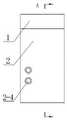
图1是本发明便携式微流控芯片操作设备的示意图;Fig. 1 is the schematic diagram of portable microfluidic chip operating equipment of the present invention;
图2是本发明便携式微流控芯片操作设备的剖视图;Fig. 2 is a cross-sectional view of the portable microfluidic chip operating device of the present invention;
图3是本发明便携式微流控芯片操作设备的可更换式顶盖组件的倒置示意图;Fig. 3 is an inverted schematic view of the replaceable top cover assembly of the portable microfluidic chip operating device of the present invention;
图4是本发明便携式微流控芯片操作设备的设备外壳组件示意图;Fig. 4 is a schematic diagram of the device shell assembly of the portable microfluidic chip operating device of the present invention;
图5是本发明便携式微流控芯片操作设备的设备外壳组件示意图;Fig. 5 is a schematic diagram of the device housing assembly of the portable microfluidic chip operating device of the present invention;
图6是本发明便携式微流控芯片操作设备的显示传输组件示意图;Fig. 6 is a schematic diagram of the display and transmission components of the portable microfluidic chip operating device of the present invention;
图7是粒子在没有电场调控时的运动轨迹;Figure 7 is the trajectory of particles when there is no electric field regulation;
图8是粒子在电场调控的作用下发生偏转的运动轨迹。Fig. 8 is the motion trajectory of particles deflected under the action of electric field regulation.
具体实施方式detailed description
下面结合附图对本发明的技术方案作进一步的说明,但并不局限于此,凡是对本发明技术方案进行修改或者等同替换,而不脱离本发明技术方案的精神和范围,均应涵盖在本发明的保护范围中。The technical solution of the present invention will be further described below in conjunction with the accompanying drawings, but it is not limited thereto. Any modification or equivalent replacement of the technical solution of the present invention without departing from the spirit and scope of the technical solution of the present invention should be covered by the present invention. within the scope of protection.
一种基于电场调控的便携式多功能可视化微流体设备,如图1-6所示,所述微流体设备包括可更换式顶盖组件1、设备外壳组件2和显示传输组件3,其中:A portable multifunctional visual microfluidic device based on electric field regulation, as shown in Figures 1-6, the microfluidic device includes a replaceable
所述可更换式顶盖组件1设置在外壳组件的上端,由送电板1-1、电场调控PCB1-2和顶盖1-3组成;The replaceable
所述外壳组件2主要用于设备整体零部件的安装和固定,由外壳2-1、送电探针2-2、可拆卸窗板2-3和按钮开关2-4组成;The
所述显示传输组件3通过螺丝安装在外壳组件的内部,主要进行微流控芯片关键结构的放大观察和图像的无线传输,由芯片座3-1、铜柱3-2、移动支架3-3、可调显微镜3-4、调焦螺栓3-5、图像传输PCB3-6、电池3-7和微流控芯片3-8组成;The
所述送电板1-1通过铰链连接在顶盖1-3的一侧,可进行180度旋转;The power transmission board 1-1 is connected to one side of the top cover 1-3 through a hinge, and can be rotated by 180 degrees;
所述顶盖1-3为开口盒式结构,电场调控PCB1-2主要进行电源信号的转化与输出,通过螺丝固定在顶盖1-3的内侧上表面上;The top cover 1-3 is an open box structure, and the electric field regulation PCB1-2 mainly performs the transformation and output of the power signal, and is fixed on the inner upper surface of the top cover 1-3 by screws;
所述外壳2-1的背部设有与送电板1-1形状匹配的凹槽,送电板1-1插入凹槽内,即可实现顶盖1-3安装;The back of the housing 2-1 is provided with a groove matching the shape of the power transmission board 1-1, and the power transmission board 1-1 is inserted into the groove to realize the installation of the top cover 1-3;
所述凹槽内部安装有两个送电探针2-2,送电探针2-2分别连在电池3-7的正负极上,用于将电源信号传输给可更换式顶盖组件1;Two power transmission probes 2-2 are installed inside the groove, and the power transmission probes 2-2 are respectively connected to the positive and negative poles of the battery 3-7 for transmitting the power signal to the replaceable
所述送电板1-1上设置有两个导电触点,将送电板1-1插入外壳2-1背部的凹槽内,送电板1-1的导电触点与送电探针2-2相接触,即可实现电路联通的功能;The power transmission board 1-1 is provided with two conductive contacts, the power transmission board 1-1 is inserted into the groove on the back of the casing 2-1, the conductive contacts of the power transmission board 1-1 and the power transmission probe 2-2 phase contact can realize the function of circuit communication;
所述外壳2-1的背部设有可拆卸窗板2-3,可拆卸窗板2-3分为上下两个相同结构的窗板,可拆卸窗板2-3通过可拆卸窗板2-3上的卡扣固定在外壳2-1上,上侧窗板拆下后可以通过放大倍数调整旋钮对可调显微镜3-4的放大倍数进行调整,下侧窗板拆下后可以通过旋转调焦螺栓3-5对可调显微镜3-4与微流控芯片3-8之间的焦距进行调整,以此满足更多的功能要求;The back of the housing 2-1 is provided with a detachable window panel 2-3, the detachable window panel 2-3 is divided into two upper and lower window panels with the same structure, and the detachable window panel 2-3 passes through the detachable window panel 2- The buckle on 3 is fixed on the shell 2-1. After the upper window plate is removed, the magnification of the adjustable microscope 3-4 can be adjusted through the magnification adjustment knob. After the lower window plate is removed, the magnification can be adjusted by rotating it. The focus bolt 3-5 adjusts the focal length between the adjustable microscope 3-4 and the microfluidic chip 3-8, so as to meet more functional requirements;
所述外壳2-1的正面左侧设有按钮开关2-4,按钮开关2-4共有上下两个,下侧开关用于开启可调显微镜3-4的光源,上侧开关用于开启电场调控PCB1-2,向微流控芯片3-8中施加电场信号;The front left side of the housing 2-1 is provided with a button switch 2-4, the button switch 2-4 has two upper and lower buttons, the lower switch is used to turn on the light source of the adjustable microscope 3-4, and the upper switch is used to turn on the electric field Regulating the PCB1-2, applying an electric field signal to the microfluidic chip 3-8;
所述铜柱3-2共有四个,上端通过螺丝与芯片座3-1相连,下端通过螺丝与外壳2-1相连,移动支架3-3与可调显微镜3-4粘接在一起,可沿铜柱3-2上下移动;There are four copper pillars 3-2, the upper end is connected with the chip seat 3-1 through screws, the lower end is connected with the shell 2-1 through screws, and the movable bracket 3-3 is bonded with the adjustable microscope 3-4, which can be Move up and down along the copper column 3-2;
所述可调显微镜3-4上设有放大倍数调整旋钮,放大倍数调整旋钮的位置与上侧窗板在同一高度上,因此拆下上侧窗板后即可观察到放大倍数调整旋钮,可以改变可调显微镜3-4自身放大倍数;可调显微镜3-4的下端设置有调焦螺栓3-5,调焦螺栓3-5的位置与下侧窗板在同一高度上,因此拆下下侧窗板后即可观察到调焦螺栓3-5,调焦螺栓3-5可以通过旋转来使可调显微镜3-4上下移动,从而改变可调显微镜3-4与微流控芯片3-8之间距离,从而实现调整焦距的功能;The adjustable microscope 3-4 is provided with a magnification adjustment knob, and the position of the magnification adjustment knob is on the same height as the upper side window plate, so the magnification adjustment knob can be observed after the upper side window plate is removed, which can Change the magnification of the adjustable microscope 3-4 itself; the lower end of the adjustable microscope 3-4 is provided with a focusing bolt 3-5, and the position of the focusing bolt 3-5 is at the same height as the lower side window plate, so remove the lower The focus bolt 3-5 can be observed behind the side window, and the focus bolt 3-5 can be rotated to move the adjustable microscope 3-4 up and down, thereby changing the relationship between the adjustable microscope 3-4 and the microfluidic chip 3-4. 8, so as to realize the function of adjusting the focal length;
所述图像传输PCB3-6安装在外壳的内侧壁上,可以实现将可调显微镜3-4采集到的图像数据通过wifi传输至接收设备,从而能够实现手机或平板电脑观测图像的功能。The image transmission PCB 3-6 is installed on the inner wall of the housing, and can transmit the image data collected by the adjustable microscope 3-4 to the receiving device through wifi, so as to realize the function of observing images by mobile phone or tablet computer.
具体操作方法如下:The specific operation method is as follows:
1、打开装置及放置微流控芯片:首先根据所需功能选择相应的顶盖组件1,并将其安装在设备外壳组件2上,由于送电板1-1和顶盖1-3之间是铰链连接,因此顶盖可以在外力作用下向上开启,开启后即可看到芯片座3-1,此时即可将微流控芯片3-8放在芯片座3-1的卡槽内,合上顶盖1-3,准备工作完成。1. Open the device and place the microfluidic chip: first, select the corresponding
2、开启显微设备:放置好芯片后,打开下侧按钮开关2-4,开启可调显微镜3-4的光源,同时使图像传输PCB3-6通电,散发wifi信号,观察到光源亮起后,即可打开手机或平板电脑等智能电子设备,连接显微设备指定的wifi,打开相应的应用程序后即可观察到图像,根所需的放大倍数,拆下上侧窗板,调整可调显微镜3-4放大倍数,随后拆下下侧窗板,调节调焦螺栓3-5,使得观察到的图像清晰,调整完成后安装好两个窗板。2. Turn on the microscope equipment: After placing the chip, turn on the button switch 2-4 on the lower side, turn on the light source of the adjustable microscope 3-4, and at the same time power on the image transmission PCB 3-6 to distribute wifi signals, and observe that the light source is on , you can turn on smart electronic devices such as mobile phones or tablets, connect to the wifi specified by the microscopic equipment, and then open the corresponding application to observe the image. According to the required magnification, remove the upper side window panel and adjust it The magnification of the microscope is 3-4, and then the lower side window plate is removed, and the focusing bolt 3-5 is adjusted to make the observed image clear, and the two window plates are installed after the adjustment is completed.
3、微流控芯片操作:打开上侧按钮开关2-4,来自电池3-7的电信号经过外壳2-1上的送电探针2-2,传送到送电板1-1和电场调控PCB1-2上,电场调控PCB1-2与微流控芯片3-8直接接触,从而实现了微流控装置电场的施加,在手机应用程序上即可看到微流控芯片3-8内液体或粒子的动作情况。3. Microfluidic chip operation: Turn on the upper button switch 2-4, the electrical signal from the battery 3-7 passes through the power transmission probe 2-2 on the shell 2-1, and transmits it to the power transmission board 1-1 and the electric field On the control PCB1-2, the electric field control PCB1-2 is in direct contact with the microfluidic chip 3-8, thereby realizing the application of the electric field of the microfluidic device, and the microfluidic chip 3-8 can be seen on the mobile phone application program. The behavior of liquids or particles.
4、关闭装置:首先关闭上侧按钮开关2-4,断开微流控芯片3-8上的电场,随后关闭下侧按钮开关,关闭可调显微镜3-4和图像传输PCB3-6,此时手机应用程序上不会再显示图像;打开顶盖1-3,取出微流控芯片3-8,合上顶盖,至此完成了微流控操作装置的关闭操作。4. Closing device: first turn off the upper button switch 2-4, disconnect the electric field on the microfluidic chip 3-8, then turn off the lower button switch, turn off the adjustable microscope 3-4 and the image transmission PCB 3-6, this At this time, the image will no longer be displayed on the mobile application; open the top cover 1-3, take out the microfluidic chip 3-8, close the top cover, and thus complete the closing operation of the microfluidic operating device.
本发明的便携式微流控芯片操作设备具有模块化的特点,可以根据不同的需要替换不同的顶盖组件;具有对微流体施加电场的功能,可以产生直流低压、低/高频低压正弦、高频低压方波等信号;所搭载的显微模块具有调整放大倍数与调整焦距的功能,可用于观察不同的芯片;可靠性好,结构紧凑,重量轻,体积小,便携性好;可在一定程度上替代函数发生器及显微镜等复杂设备,满足微流控芯片操作与观察的使用要求。The portable microfluidic chip operating device of the present invention has the characteristics of modularization, and can replace different top cover components according to different needs; it has the function of applying an electric field to the microfluid, and can generate DC low voltage, low/high frequency low voltage sine, high High frequency and low voltage square wave and other signals; the equipped micro module has the function of adjusting magnification and adjusting focus, which can be used to observe different chips; it has good reliability, compact structure, light weight, small size and good portability; it can be used in a certain To a certain extent, it can replace complex equipment such as function generators and microscopes, and meet the requirements for the operation and observation of microfluidic chips.
实施例:Example:
以利用介电泳实现粒子偏转的功能为例,电场调控PCB1-2可以通过电路产生16Vpp、1MHz的电信号,微流控芯片内原本的粒子如图7所示,粒子从左向右运动,可以看到右边两个出口内都有粒子。按下位于上侧的按钮开关2-4,使顶盖组件电路联通,即可对芯片施加电场信号,粒子偏转后如图8所示。从图8可以看出,粒子在电场作用下都实现了向上偏转。Taking the function of using dielectrophoresis to achieve particle deflection as an example, the electric field regulation PCB1-2 can generate 16Vpp, 1MHz electrical signals through the circuit. The original particles in the microfluidic chip are shown in Figure 7. The particles move from left to right. See that there are particles in the two exits on the right. Press the button switch 2-4 on the upper side to connect the circuit of the top cover component, and then apply an electric field signal to the chip, and the particles are deflected as shown in Figure 8. It can be seen from Figure 8 that the particles are deflected upward under the action of the electric field.
该装置可以快速的检测不同电压频率对微流控芯片的影响,例如快速观察粒子大小变化,电压频率变化对粒子运动的影响。The device can quickly detect the influence of different voltage frequencies on the microfluidic chip, such as quickly observing the changes in particle size and the influence of voltage frequency changes on particle motion.
Claims (7)
Priority Applications (1)
| Application Number | Priority Date | Filing Date | Title |
|---|---|---|---|
| CN202111573617.9ACN114210377B (en) | 2021-12-21 | 2021-12-21 | A Portable Multifunctional Visual Microfluidic Device Based on Electric Field Regulation |
Applications Claiming Priority (1)
| Application Number | Priority Date | Filing Date | Title |
|---|---|---|---|
| CN202111573617.9ACN114210377B (en) | 2021-12-21 | 2021-12-21 | A Portable Multifunctional Visual Microfluidic Device Based on Electric Field Regulation |
Publications (2)
| Publication Number | Publication Date |
|---|---|
| CN114210377A CN114210377A (en) | 2022-03-22 |
| CN114210377Btrue CN114210377B (en) | 2023-01-06 |
Family
ID=80704774
Family Applications (1)
| Application Number | Title | Priority Date | Filing Date |
|---|---|---|---|
| CN202111573617.9AExpired - Fee RelatedCN114210377B (en) | 2021-12-21 | 2021-12-21 | A Portable Multifunctional Visual Microfluidic Device Based on Electric Field Regulation |
Country Status (1)
| Country | Link |
|---|---|
| CN (1) | CN114210377B (en) |
Families Citing this family (1)
| Publication number | Priority date | Publication date | Assignee | Title |
|---|---|---|---|---|
| CN115193497A (en)* | 2022-07-19 | 2022-10-18 | 哈尔滨工业大学 | Portable micro-fluidic chip operating device with complicated electric field regulation and control function |
Citations (7)
| Publication number | Priority date | Publication date | Assignee | Title |
|---|---|---|---|---|
| CN101464251A (en)* | 2008-12-31 | 2009-06-24 | 厦门大学 | Micro-fluid controlled optical detector with microscope interface |
| BRPI0721509A2 (en)* | 2007-03-26 | 2013-01-15 | Fundacion Gaiker | Method and device for detection of genetic material by polymerase chain reaction |
| CN103224878A (en)* | 2013-05-08 | 2013-07-31 | 中山大学达安基因股份有限公司 | Gene chip based detection apparatus |
| CN104668002A (en)* | 2014-05-22 | 2015-06-03 | Imec非营利协会 | Compact fluid analysis device and method of manufacturing the same |
| CN106662522A (en)* | 2014-06-18 | 2017-05-10 | 斯堪的纳维亚微生物制剂公司 | Microfluidic detection system and microfluidic box |
| CN206223667U (en)* | 2016-10-26 | 2017-06-06 | 华南理工大学 | A kind of intelligent detection device of medicine detection micro-fluidic chip |
| CN107101581A (en)* | 2017-06-26 | 2017-08-29 | 东北电力大学 | The alignment device and assembly method of a kind of micro-nano-fluidic control chip |
Family Cites Families (9)
| Publication number | Priority date | Publication date | Assignee | Title |
|---|---|---|---|---|
| US7452507B2 (en)* | 2002-08-02 | 2008-11-18 | Sandia Corporation | Portable apparatus for separating sample and detecting target analytes |
| US8153059B2 (en)* | 2005-07-25 | 2012-04-10 | Fraunhofer-Gesellschaft Zur Foerderung Der Angewandten Forschung E.V. | Chip-holder for a micro-fluidic chip |
| US8613889B2 (en)* | 2006-04-13 | 2013-12-24 | Advanced Liquid Logic, Inc. | Droplet-based washing |
| WO2014040185A1 (en)* | 2012-09-14 | 2014-03-20 | University Of Manitoba | Low-cost portable microfluidic system for cell migration studies |
| US9523642B2 (en)* | 2012-11-09 | 2016-12-20 | Taiwan Semiconductor Manufacturing Company, Ltd. | Integrated electro-microfluidic probe card, system and method for using the same |
| WO2014100725A1 (en)* | 2012-12-21 | 2014-06-26 | Micronics, Inc. | Portable fluorescence detection system and microassay cartridge |
| WO2017091618A1 (en)* | 2015-11-25 | 2017-06-01 | Spectradyne, Llc | Systems and devices for microfluidic instrumentation |
| WO2020038461A1 (en)* | 2018-08-23 | 2020-02-27 | Sanwa Biotech Ltd | Portable diagnostic apparatus and the method thereof |
| US20210301245A1 (en)* | 2020-03-29 | 2021-09-30 | Agilent Technologies, Inc. | Systems and methods for electronically and optically monitoring biological samples |
- 2021
- 2021-12-21CNCN202111573617.9Apatent/CN114210377B/ennot_activeExpired - Fee Related
Patent Citations (7)
| Publication number | Priority date | Publication date | Assignee | Title |
|---|---|---|---|---|
| BRPI0721509A2 (en)* | 2007-03-26 | 2013-01-15 | Fundacion Gaiker | Method and device for detection of genetic material by polymerase chain reaction |
| CN101464251A (en)* | 2008-12-31 | 2009-06-24 | 厦门大学 | Micro-fluid controlled optical detector with microscope interface |
| CN103224878A (en)* | 2013-05-08 | 2013-07-31 | 中山大学达安基因股份有限公司 | Gene chip based detection apparatus |
| CN104668002A (en)* | 2014-05-22 | 2015-06-03 | Imec非营利协会 | Compact fluid analysis device and method of manufacturing the same |
| CN106662522A (en)* | 2014-06-18 | 2017-05-10 | 斯堪的纳维亚微生物制剂公司 | Microfluidic detection system and microfluidic box |
| CN206223667U (en)* | 2016-10-26 | 2017-06-06 | 华南理工大学 | A kind of intelligent detection device of medicine detection micro-fluidic chip |
| CN107101581A (en)* | 2017-06-26 | 2017-08-29 | 东北电力大学 | The alignment device and assembly method of a kind of micro-nano-fluidic control chip |
Non-Patent Citations (1)
| Title |
|---|
| 《多层复合结构微流控芯片关键技术研究》;赵林;《中国优秀硕士学位论文全文数据库》;20140315;I135-239* |
Also Published As
| Publication number | Publication date |
|---|---|
| CN114210377A (en) | 2022-03-22 |
Similar Documents
| Publication | Publication Date | Title |
|---|---|---|
| CN114210377B (en) | A Portable Multifunctional Visual Microfluidic Device Based on Electric Field Regulation | |
| Pethig | Where is dielectrophoresis (DEP) going? | |
| Yang et al. | Dielectrophoretic separation of colorectal cancer cells | |
| Kung et al. | Tunnel dielectrophoresis for tunable, single‐stream cell focusing in physiological buffers in high‐speed microfluidic flows | |
| Tay et al. | Electrical and thermal characterization of a dielectrophoretic chip with 3D electrodes for cells manipulation | |
| Lin et al. | An optically induced cell lysis device using dielectrophoresis | |
| WO2021244002A1 (en) | Triboelectric nanogenerator-based biochemical droplet reaction device and method | |
| Huang et al. | Three-dimensional cellular focusing utilizing a combination of insulator-based and metallic dielectrophoresis | |
| CN118179620A (en) | Portable micro-fluidic chip experimental device with multiple electric field regulation and control functions | |
| CN111644215B (en) | Liquid metal micro-fluidic mixing device | |
| TWI399488B (en) | A microfluidic driving system | |
| US11642668B2 (en) | Method and device of nondestructive transfer of liquid drops and method of micro-reaction of liquid drops | |
| CN111239202B (en) | A kind of microfluidic chip non-contact conductivity detection device and preparation method | |
| Park et al. | Quantitative characterization for dielectrophoretic behavior of biological cells using optical tweezers | |
| Liang et al. | An equivalent electrical model for numerical analyses of ODEP manipulation | |
| CN115193497A (en) | Portable micro-fluidic chip operating device with complicated electric field regulation and control function | |
| Puri et al. | Design, simulation and fabrication of MEMS based dielectrophoretic separator for bio-particles | |
| CN102402336A (en) | Energy-saving LCD (liquid crystal display) device | |
| Qian et al. | Integrated planar concentric ring dielectrophoretic (DEP) levitator | |
| CN215311622U (en) | Medicine agitator is used in special chemistry experiment teaching of secondary school | |
| Edwards et al. | Electric tweezers: negative dielectrophoretic multiple particle positioning | |
| CN211771334U (en) | Nucleic acid amplification reaction detection device | |
| CN210015605U (en) | A chemical experiment demonstration platform | |
| CN215428301U (en) | A can dismantle agitating unit for laboratory | |
| Sun et al. | Self-powered droplet manipulation for full human-droplet interaction in multiple mediums |
Legal Events
| Date | Code | Title | Description |
|---|---|---|---|
| PB01 | Publication | ||
| PB01 | Publication | ||
| SE01 | Entry into force of request for substantive examination | ||
| SE01 | Entry into force of request for substantive examination | ||
| GR01 | Patent grant | ||
| GR01 | Patent grant | ||
| CF01 | Termination of patent right due to non-payment of annual fee | ||
| CF01 | Termination of patent right due to non-payment of annual fee | Granted publication date:20230106 |