CN114126537A - Frames with different strut widths for prosthetic implants - Google Patents
Frames with different strut widths for prosthetic implantsDownload PDFInfo
- Publication number
- CN114126537A CN114126537ACN202080046355.8ACN202080046355ACN114126537ACN 114126537 ACN114126537 ACN 114126537ACN 202080046355 ACN202080046355 ACN 202080046355ACN 114126537 ACN114126537 ACN 114126537A
- Authority
- CN
- China
- Prior art keywords
- struts
- strut
- prosthetic implant
- frame
- prosthetic
- Prior art date
- Legal status (The legal status is an assumption and is not a legal conclusion. Google has not performed a legal analysis and makes no representation as to the accuracy of the status listed.)
- Pending
Links
- 239000007943implantSubstances0.000titleclaimsabstractdescription288
- 230000002829reductive effectEffects0.000claimsabstractdescription44
- 210000003709heart valveAnatomy0.000claimsdescription71
- 238000003032molecular dockingMethods0.000claimsdescription66
- 238000013461designMethods0.000claimsdescription34
- 238000000034methodMethods0.000claimsdescription26
- 239000008280bloodSubstances0.000claimsdescription18
- 210000004369bloodAnatomy0.000claimsdescription18
- 230000000717retained effectEffects0.000claimsdescription12
- 230000014759maintenance of locationEffects0.000description41
- 230000007246mechanismEffects0.000description37
- 238000002513implantationMethods0.000description24
- 229910052751metalInorganic materials0.000description23
- 239000002184metalSubstances0.000description23
- 239000000463materialSubstances0.000description17
- 230000008901benefitEffects0.000description8
- 230000008878couplingEffects0.000description8
- 238000010168coupling processMethods0.000description8
- 238000005859coupling reactionMethods0.000description8
- 238000003698laser cuttingMethods0.000description8
- 210000001519tissueAnatomy0.000description8
- 210000005166vasculatureAnatomy0.000description8
- 230000001684chronic effectEffects0.000description7
- 239000004744fabricSubstances0.000description7
- 229910001000nickel titaniumInorganic materials0.000description7
- 238000007789sealingMethods0.000description7
- 210000003484anatomyAnatomy0.000description6
- 210000001765aortic valveAnatomy0.000description6
- 230000000694effectsEffects0.000description6
- 210000004115mitral valveAnatomy0.000description6
- HLXZNVUGXRDIFK-UHFFFAOYSA-Nnickel titaniumChemical compound[Ti].[Ti].[Ti].[Ti].[Ti].[Ti].[Ti].[Ti].[Ti].[Ti].[Ti].[Ni].[Ni].[Ni].[Ni].[Ni].[Ni].[Ni].[Ni].[Ni].[Ni].[Ni].[Ni].[Ni].[Ni]HLXZNVUGXRDIFK-UHFFFAOYSA-N0.000description6
- 230000002787reinforcementEffects0.000description6
- 238000004873anchoringMethods0.000description5
- 210000000709aortaAnatomy0.000description5
- 238000005452bendingMethods0.000description5
- 238000005520cutting processMethods0.000description5
- 229920000139polyethylene terephthalatePolymers0.000description5
- 239000005020polyethylene terephthalateSubstances0.000description5
- 229920000642polymerPolymers0.000description5
- 229920001343polytetrafluoroethylenePolymers0.000description5
- 239000004810polytetrafluoroethyleneSubstances0.000description5
- 230000008569processEffects0.000description5
- 230000017531blood circulationEffects0.000description4
- 239000002131composite materialSubstances0.000description4
- 238000002788crimpingMethods0.000description4
- 230000036961partial effectEffects0.000description4
- -1polytetrafluoroethylenePolymers0.000description4
- 210000001147pulmonary arteryAnatomy0.000description4
- 239000012781shape memory materialSubstances0.000description4
- 210000003291sinus of valsalvaAnatomy0.000description4
- 210000004204blood vesselAnatomy0.000description3
- 210000004375bundle of hisAnatomy0.000description3
- 210000001105femoral arteryAnatomy0.000description3
- 230000000670limiting effectEffects0.000description3
- 238000012360testing methodMethods0.000description3
- 238000011282treatmentMethods0.000description3
- 210000002376aorta thoracicAnatomy0.000description2
- 238000013459approachMethods0.000description2
- 210000001367arteryAnatomy0.000description2
- 239000012620biological materialSubstances0.000description2
- 230000006835compressionEffects0.000description2
- 238000007906compressionMethods0.000description2
- 230000002950deficientEffects0.000description2
- 238000005516engineering processMethods0.000description2
- 239000012530fluidSubstances0.000description2
- 239000006260foamSubstances0.000description2
- 230000006870functionEffects0.000description2
- 238000007373indentationMethods0.000description2
- 238000003780insertionMethods0.000description2
- 230000037431insertionEffects0.000description2
- 210000005240left ventricleAnatomy0.000description2
- 238000005259measurementMethods0.000description2
- 150000002739metalsChemical class0.000description2
- 229910000623nickel–chromium alloyInorganic materials0.000description2
- 210000003516pericardiumAnatomy0.000description2
- 229920000728polyesterPolymers0.000description2
- 230000009467reductionEffects0.000description2
- 230000003014reinforcing effectEffects0.000description2
- XGVXKJKTISMIOW-ZDUSSCGKSA-NsimurosertibChemical compoundN1N=CC(C=2SC=3C(=O)NC(=NC=3C=2)[C@H]2N3CCC(CC3)C2)=C1CXGVXKJKTISMIOW-ZDUSSCGKSA-N0.000description2
- 239000010935stainless steelSubstances0.000description2
- 229910001220stainless steelInorganic materials0.000description2
- 230000002966stenotic effectEffects0.000description2
- 238000001356surgical procedureMethods0.000description2
- 229920002994synthetic fiberPolymers0.000description2
- VCGRFBXVSFAGGA-UHFFFAOYSA-N(1,1-dioxo-1,4-thiazinan-4-yl)-[6-[[3-(4-fluorophenyl)-5-methyl-1,2-oxazol-4-yl]methoxy]pyridin-3-yl]methanoneChemical compoundCC=1ON=C(C=2C=CC(F)=CC=2)C=1COC(N=C1)=CC=C1C(=O)N1CCS(=O)(=O)CC1VCGRFBXVSFAGGA-UHFFFAOYSA-N0.000description1
- CYJRNFFLTBEQSQ-UHFFFAOYSA-N8-(3-methyl-1-benzothiophen-5-yl)-N-(4-methylsulfonylpyridin-3-yl)quinoxalin-6-amineChemical compoundCS(=O)(=O)C1=C(C=NC=C1)NC=1C=C2N=CC=NC2=C(C=1)C=1C=CC2=C(C(=CS2)C)C=1CYJRNFFLTBEQSQ-UHFFFAOYSA-N0.000description1
- 241000283690Bos taurusSpecies0.000description1
- 206010010356Congenital anomalyDiseases0.000description1
- 101000794285Drosophila melanogaster CDC42 small effector protein homologProteins0.000description1
- 241000283073Equus caballusSpecies0.000description1
- AYCPARAPKDAOEN-LJQANCHMSA-NN-[(1S)-2-(dimethylamino)-1-phenylethyl]-6,6-dimethyl-3-[(2-methyl-4-thieno[3,2-d]pyrimidinyl)amino]-1,4-dihydropyrrolo[3,4-c]pyrazole-5-carboxamideChemical compoundC1([C@H](NC(=O)N2C(C=3NN=C(NC=4C=5SC=CC=5N=C(C)N=4)C=3C2)(C)C)CN(C)C)=CC=CC=C1AYCPARAPKDAOEN-LJQANCHMSA-N0.000description1
- 230000003187abdominal effectEffects0.000description1
- 239000000853adhesiveSubstances0.000description1
- 230000001070adhesive effectEffects0.000description1
- 230000002411adverseEffects0.000description1
- 229910045601alloyInorganic materials0.000description1
- 239000000956alloySubstances0.000description1
- 238000013158balloon valvuloplastyMethods0.000description1
- 239000000560biocompatible materialSubstances0.000description1
- 230000015572biosynthetic processEffects0.000description1
- 230000036770blood supplyEffects0.000description1
- 230000000747cardiac effectEffects0.000description1
- 230000004087circulationEffects0.000description1
- 238000004140cleaningMethods0.000description1
- 230000035602clottingEffects0.000description1
- 239000011248coating agentSubstances0.000description1
- 238000000576coating methodMethods0.000description1
- 230000003247decreasing effectEffects0.000description1
- 238000011257definitive treatmentMethods0.000description1
- 229910003460diamondInorganic materials0.000description1
- 239000010432diamondSubstances0.000description1
- 201000010099diseaseDiseases0.000description1
- 208000037265diseases, disorders, signs and symptomsDiseases0.000description1
- 238000006073displacement reactionMethods0.000description1
- 238000009826distributionMethods0.000description1
- 230000002526effect on cardiovascular systemEffects0.000description1
- 238000005538encapsulationMethods0.000description1
- 230000007613environmental effectEffects0.000description1
- 238000005530etchingMethods0.000description1
- 238000011156evaluationMethods0.000description1
- 238000011010flushing procedureMethods0.000description1
- 208000018578heart valve diseaseDiseases0.000description1
- 208000015181infectious diseaseDiseases0.000description1
- 230000002458infectious effectEffects0.000description1
- 230000002757inflammatory effectEffects0.000description1
- 230000001788irregularEffects0.000description1
- 210000004072lungAnatomy0.000description1
- 238000003754machiningMethods0.000description1
- 229910001092metal group alloyInorganic materials0.000description1
- 239000007769metal materialSubstances0.000description1
- 238000013508migrationMethods0.000description1
- 230000005012migrationEffects0.000description1
- 239000000203mixtureSubstances0.000description1
- 239000002861polymer materialSubstances0.000description1
- 238000011176poolingMethods0.000description1
- 230000002028prematureEffects0.000description1
- 238000003825pressingMethods0.000description1
- 230000002685pulmonary effectEffects0.000description1
- 210000003102pulmonary valveAnatomy0.000description1
- 230000008707rearrangementEffects0.000description1
- 239000012925reference materialSubstances0.000description1
- 230000008439repair processEffects0.000description1
- 230000002441reversible effectEffects0.000description1
- 239000003566sealing materialSubstances0.000description1
- 238000000926separation methodMethods0.000description1
- 238000007493shaping processMethods0.000description1
- 238000004904shorteningMethods0.000description1
- 230000011664signalingEffects0.000description1
- 208000024891symptomDiseases0.000description1
- 238000012546transferMethods0.000description1
- 238000013519translationMethods0.000description1
- 238000011144upstream manufacturingMethods0.000description1
- 210000002073venous valveAnatomy0.000description1
- 238000003466weldingMethods0.000description1
Images


Classifications
- A—HUMAN NECESSITIES
- A61—MEDICAL OR VETERINARY SCIENCE; HYGIENE
- A61F—FILTERS IMPLANTABLE INTO BLOOD VESSELS; PROSTHESES; DEVICES PROVIDING PATENCY TO, OR PREVENTING COLLAPSING OF, TUBULAR STRUCTURES OF THE BODY, e.g. STENTS; ORTHOPAEDIC, NURSING OR CONTRACEPTIVE DEVICES; FOMENTATION; TREATMENT OR PROTECTION OF EYES OR EARS; BANDAGES, DRESSINGS OR ABSORBENT PADS; FIRST-AID KITS
- A61F2/00—Filters implantable into blood vessels; Prostheses, i.e. artificial substitutes or replacements for parts of the body; Appliances for connecting them with the body; Devices providing patency to, or preventing collapsing of, tubular structures of the body, e.g. stents
- A61F2/02—Prostheses implantable into the body
- A61F2/24—Heart valves ; Vascular valves, e.g. venous valves; Heart implants, e.g. passive devices for improving the function of the native valve or the heart muscle; Transmyocardial revascularisation [TMR] devices; Valves implantable in the body
- A61F2/2412—Heart valves ; Vascular valves, e.g. venous valves; Heart implants, e.g. passive devices for improving the function of the native valve or the heart muscle; Transmyocardial revascularisation [TMR] devices; Valves implantable in the body with soft flexible valve members, e.g. tissue valves shaped like natural valves
- A61F2/2418—Scaffolds therefor, e.g. support stents
- A—HUMAN NECESSITIES
- A61—MEDICAL OR VETERINARY SCIENCE; HYGIENE
- A61F—FILTERS IMPLANTABLE INTO BLOOD VESSELS; PROSTHESES; DEVICES PROVIDING PATENCY TO, OR PREVENTING COLLAPSING OF, TUBULAR STRUCTURES OF THE BODY, e.g. STENTS; ORTHOPAEDIC, NURSING OR CONTRACEPTIVE DEVICES; FOMENTATION; TREATMENT OR PROTECTION OF EYES OR EARS; BANDAGES, DRESSINGS OR ABSORBENT PADS; FIRST-AID KITS
- A61F2/00—Filters implantable into blood vessels; Prostheses, i.e. artificial substitutes or replacements for parts of the body; Appliances for connecting them with the body; Devices providing patency to, or preventing collapsing of, tubular structures of the body, e.g. stents
- A61F2/02—Prostheses implantable into the body
- A61F2/24—Heart valves ; Vascular valves, e.g. venous valves; Heart implants, e.g. passive devices for improving the function of the native valve or the heart muscle; Transmyocardial revascularisation [TMR] devices; Valves implantable in the body
- A61F2/2427—Devices for manipulating or deploying heart valves during implantation
- A61F2/243—Deployment by mechanical expansion
- A61F2/2433—Deployment by mechanical expansion using balloon catheter
- A—HUMAN NECESSITIES
- A61—MEDICAL OR VETERINARY SCIENCE; HYGIENE
- A61F—FILTERS IMPLANTABLE INTO BLOOD VESSELS; PROSTHESES; DEVICES PROVIDING PATENCY TO, OR PREVENTING COLLAPSING OF, TUBULAR STRUCTURES OF THE BODY, e.g. STENTS; ORTHOPAEDIC, NURSING OR CONTRACEPTIVE DEVICES; FOMENTATION; TREATMENT OR PROTECTION OF EYES OR EARS; BANDAGES, DRESSINGS OR ABSORBENT PADS; FIRST-AID KITS
- A61F2/00—Filters implantable into blood vessels; Prostheses, i.e. artificial substitutes or replacements for parts of the body; Appliances for connecting them with the body; Devices providing patency to, or preventing collapsing of, tubular structures of the body, e.g. stents
- A61F2/02—Prostheses implantable into the body
- A61F2/24—Heart valves ; Vascular valves, e.g. venous valves; Heart implants, e.g. passive devices for improving the function of the native valve or the heart muscle; Transmyocardial revascularisation [TMR] devices; Valves implantable in the body
- A61F2/2427—Devices for manipulating or deploying heart valves during implantation
- A61F2/2436—Deployment by retracting a sheath
- A—HUMAN NECESSITIES
- A61—MEDICAL OR VETERINARY SCIENCE; HYGIENE
- A61F—FILTERS IMPLANTABLE INTO BLOOD VESSELS; PROSTHESES; DEVICES PROVIDING PATENCY TO, OR PREVENTING COLLAPSING OF, TUBULAR STRUCTURES OF THE BODY, e.g. STENTS; ORTHOPAEDIC, NURSING OR CONTRACEPTIVE DEVICES; FOMENTATION; TREATMENT OR PROTECTION OF EYES OR EARS; BANDAGES, DRESSINGS OR ABSORBENT PADS; FIRST-AID KITS
- A61F2/00—Filters implantable into blood vessels; Prostheses, i.e. artificial substitutes or replacements for parts of the body; Appliances for connecting them with the body; Devices providing patency to, or preventing collapsing of, tubular structures of the body, e.g. stents
- A61F2/02—Prostheses implantable into the body
- A61F2/24—Heart valves ; Vascular valves, e.g. venous valves; Heart implants, e.g. passive devices for improving the function of the native valve or the heart muscle; Transmyocardial revascularisation [TMR] devices; Valves implantable in the body
- A61F2/2427—Devices for manipulating or deploying heart valves during implantation
- A61F2/2439—Expansion controlled by filaments
- A—HUMAN NECESSITIES
- A61—MEDICAL OR VETERINARY SCIENCE; HYGIENE
- A61F—FILTERS IMPLANTABLE INTO BLOOD VESSELS; PROSTHESES; DEVICES PROVIDING PATENCY TO, OR PREVENTING COLLAPSING OF, TUBULAR STRUCTURES OF THE BODY, e.g. STENTS; ORTHOPAEDIC, NURSING OR CONTRACEPTIVE DEVICES; FOMENTATION; TREATMENT OR PROTECTION OF EYES OR EARS; BANDAGES, DRESSINGS OR ABSORBENT PADS; FIRST-AID KITS
- A61F2/00—Filters implantable into blood vessels; Prostheses, i.e. artificial substitutes or replacements for parts of the body; Appliances for connecting them with the body; Devices providing patency to, or preventing collapsing of, tubular structures of the body, e.g. stents
- A61F2/82—Devices providing patency to, or preventing collapsing of, tubular structures of the body, e.g. stents
- A61F2/86—Stents in a form characterised by the wire-like elements; Stents in the form characterised by a net-like or mesh-like structure
- A61F2/90—Stents in a form characterised by the wire-like elements; Stents in the form characterised by a net-like or mesh-like structure characterised by a net-like or mesh-like structure
- A61F2/91—Stents in a form characterised by the wire-like elements; Stents in the form characterised by a net-like or mesh-like structure characterised by a net-like or mesh-like structure made from perforated sheets or tubes, e.g. perforated by laser cuts or etched holes
- A—HUMAN NECESSITIES
- A61—MEDICAL OR VETERINARY SCIENCE; HYGIENE
- A61F—FILTERS IMPLANTABLE INTO BLOOD VESSELS; PROSTHESES; DEVICES PROVIDING PATENCY TO, OR PREVENTING COLLAPSING OF, TUBULAR STRUCTURES OF THE BODY, e.g. STENTS; ORTHOPAEDIC, NURSING OR CONTRACEPTIVE DEVICES; FOMENTATION; TREATMENT OR PROTECTION OF EYES OR EARS; BANDAGES, DRESSINGS OR ABSORBENT PADS; FIRST-AID KITS
- A61F2/00—Filters implantable into blood vessels; Prostheses, i.e. artificial substitutes or replacements for parts of the body; Appliances for connecting them with the body; Devices providing patency to, or preventing collapsing of, tubular structures of the body, e.g. stents
- A61F2/95—Instruments specially adapted for placement or removal of stents or stent-grafts
- A61F2/9517—Instruments specially adapted for placement or removal of stents or stent-grafts handle assemblies therefor
- A—HUMAN NECESSITIES
- A61—MEDICAL OR VETERINARY SCIENCE; HYGIENE
- A61F—FILTERS IMPLANTABLE INTO BLOOD VESSELS; PROSTHESES; DEVICES PROVIDING PATENCY TO, OR PREVENTING COLLAPSING OF, TUBULAR STRUCTURES OF THE BODY, e.g. STENTS; ORTHOPAEDIC, NURSING OR CONTRACEPTIVE DEVICES; FOMENTATION; TREATMENT OR PROTECTION OF EYES OR EARS; BANDAGES, DRESSINGS OR ABSORBENT PADS; FIRST-AID KITS
- A61F2/00—Filters implantable into blood vessels; Prostheses, i.e. artificial substitutes or replacements for parts of the body; Appliances for connecting them with the body; Devices providing patency to, or preventing collapsing of, tubular structures of the body, e.g. stents
- A61F2/95—Instruments specially adapted for placement or removal of stents or stent-grafts
- A61F2/9522—Means for mounting a stent or stent-graft onto or into a placement instrument
- A61F2/9524—Iris-type crimpers
- A—HUMAN NECESSITIES
- A61—MEDICAL OR VETERINARY SCIENCE; HYGIENE
- A61F—FILTERS IMPLANTABLE INTO BLOOD VESSELS; PROSTHESES; DEVICES PROVIDING PATENCY TO, OR PREVENTING COLLAPSING OF, TUBULAR STRUCTURES OF THE BODY, e.g. STENTS; ORTHOPAEDIC, NURSING OR CONTRACEPTIVE DEVICES; FOMENTATION; TREATMENT OR PROTECTION OF EYES OR EARS; BANDAGES, DRESSINGS OR ABSORBENT PADS; FIRST-AID KITS
- A61F2/00—Filters implantable into blood vessels; Prostheses, i.e. artificial substitutes or replacements for parts of the body; Appliances for connecting them with the body; Devices providing patency to, or preventing collapsing of, tubular structures of the body, e.g. stents
- A61F2/95—Instruments specially adapted for placement or removal of stents or stent-grafts
- A61F2002/9534—Instruments specially adapted for placement or removal of stents or stent-grafts for repositioning of stents
- A—HUMAN NECESSITIES
- A61—MEDICAL OR VETERINARY SCIENCE; HYGIENE
- A61F—FILTERS IMPLANTABLE INTO BLOOD VESSELS; PROSTHESES; DEVICES PROVIDING PATENCY TO, OR PREVENTING COLLAPSING OF, TUBULAR STRUCTURES OF THE BODY, e.g. STENTS; ORTHOPAEDIC, NURSING OR CONTRACEPTIVE DEVICES; FOMENTATION; TREATMENT OR PROTECTION OF EYES OR EARS; BANDAGES, DRESSINGS OR ABSORBENT PADS; FIRST-AID KITS
- A61F2230/00—Geometry of prostheses classified in groups A61F2/00 - A61F2/26 or A61F2/82 or A61F9/00 or A61F11/00 or subgroups thereof
- A61F2230/0002—Two-dimensional shapes, e.g. cross-sections
- A61F2230/0004—Rounded shapes, e.g. with rounded corners
- A61F2230/001—Figure-8-shaped, e.g. hourglass-shaped
- A—HUMAN NECESSITIES
- A61—MEDICAL OR VETERINARY SCIENCE; HYGIENE
- A61F—FILTERS IMPLANTABLE INTO BLOOD VESSELS; PROSTHESES; DEVICES PROVIDING PATENCY TO, OR PREVENTING COLLAPSING OF, TUBULAR STRUCTURES OF THE BODY, e.g. STENTS; ORTHOPAEDIC, NURSING OR CONTRACEPTIVE DEVICES; FOMENTATION; TREATMENT OR PROTECTION OF EYES OR EARS; BANDAGES, DRESSINGS OR ABSORBENT PADS; FIRST-AID KITS
- A61F2230/00—Geometry of prostheses classified in groups A61F2/00 - A61F2/26 or A61F2/82 or A61F9/00 or A61F11/00 or subgroups thereof
- A61F2230/0002—Two-dimensional shapes, e.g. cross-sections
- A61F2230/0028—Shapes in the form of latin or greek characters
- A61F2230/0039—H-shaped
- A—HUMAN NECESSITIES
- A61—MEDICAL OR VETERINARY SCIENCE; HYGIENE
- A61F—FILTERS IMPLANTABLE INTO BLOOD VESSELS; PROSTHESES; DEVICES PROVIDING PATENCY TO, OR PREVENTING COLLAPSING OF, TUBULAR STRUCTURES OF THE BODY, e.g. STENTS; ORTHOPAEDIC, NURSING OR CONTRACEPTIVE DEVICES; FOMENTATION; TREATMENT OR PROTECTION OF EYES OR EARS; BANDAGES, DRESSINGS OR ABSORBENT PADS; FIRST-AID KITS
- A61F2230/00—Geometry of prostheses classified in groups A61F2/00 - A61F2/26 or A61F2/82 or A61F9/00 or A61F11/00 or subgroups thereof
- A61F2230/0002—Two-dimensional shapes, e.g. cross-sections
- A61F2230/0028—Shapes in the form of latin or greek characters
- A61F2230/005—Rosette-shaped, e.g. star-shaped
- A—HUMAN NECESSITIES
- A61—MEDICAL OR VETERINARY SCIENCE; HYGIENE
- A61F—FILTERS IMPLANTABLE INTO BLOOD VESSELS; PROSTHESES; DEVICES PROVIDING PATENCY TO, OR PREVENTING COLLAPSING OF, TUBULAR STRUCTURES OF THE BODY, e.g. STENTS; ORTHOPAEDIC, NURSING OR CONTRACEPTIVE DEVICES; FOMENTATION; TREATMENT OR PROTECTION OF EYES OR EARS; BANDAGES, DRESSINGS OR ABSORBENT PADS; FIRST-AID KITS
- A61F2230/00—Geometry of prostheses classified in groups A61F2/00 - A61F2/26 or A61F2/82 or A61F9/00 or A61F11/00 or subgroups thereof
- A61F2230/0002—Two-dimensional shapes, e.g. cross-sections
- A61F2230/0028—Shapes in the form of latin or greek characters
- A61F2230/0054—V-shaped
- A—HUMAN NECESSITIES
- A61—MEDICAL OR VETERINARY SCIENCE; HYGIENE
- A61F—FILTERS IMPLANTABLE INTO BLOOD VESSELS; PROSTHESES; DEVICES PROVIDING PATENCY TO, OR PREVENTING COLLAPSING OF, TUBULAR STRUCTURES OF THE BODY, e.g. STENTS; ORTHOPAEDIC, NURSING OR CONTRACEPTIVE DEVICES; FOMENTATION; TREATMENT OR PROTECTION OF EYES OR EARS; BANDAGES, DRESSINGS OR ABSORBENT PADS; FIRST-AID KITS
- A61F2250/00—Special features of prostheses classified in groups A61F2/00 - A61F2/26 or A61F2/82 or A61F9/00 or A61F11/00 or subgroups thereof
- A61F2250/0004—Special features of prostheses classified in groups A61F2/00 - A61F2/26 or A61F2/82 or A61F9/00 or A61F11/00 or subgroups thereof adjustable
- A61F2250/001—Special features of prostheses classified in groups A61F2/00 - A61F2/26 or A61F2/82 or A61F9/00 or A61F11/00 or subgroups thereof adjustable for adjusting a diameter
- A—HUMAN NECESSITIES
- A61—MEDICAL OR VETERINARY SCIENCE; HYGIENE
- A61F—FILTERS IMPLANTABLE INTO BLOOD VESSELS; PROSTHESES; DEVICES PROVIDING PATENCY TO, OR PREVENTING COLLAPSING OF, TUBULAR STRUCTURES OF THE BODY, e.g. STENTS; ORTHOPAEDIC, NURSING OR CONTRACEPTIVE DEVICES; FOMENTATION; TREATMENT OR PROTECTION OF EYES OR EARS; BANDAGES, DRESSINGS OR ABSORBENT PADS; FIRST-AID KITS
- A61F2250/00—Special features of prostheses classified in groups A61F2/00 - A61F2/26 or A61F2/82 or A61F9/00 or A61F11/00 or subgroups thereof
- A61F2250/0014—Special features of prostheses classified in groups A61F2/00 - A61F2/26 or A61F2/82 or A61F9/00 or A61F11/00 or subgroups thereof having different values of a given property or geometrical feature, e.g. mechanical property or material property, at different locations within the same prosthesis
- A61F2250/0036—Special features of prostheses classified in groups A61F2/00 - A61F2/26 or A61F2/82 or A61F9/00 or A61F11/00 or subgroups thereof having different values of a given property or geometrical feature, e.g. mechanical property or material property, at different locations within the same prosthesis differing in thickness
- A—HUMAN NECESSITIES
- A61—MEDICAL OR VETERINARY SCIENCE; HYGIENE
- A61F—FILTERS IMPLANTABLE INTO BLOOD VESSELS; PROSTHESES; DEVICES PROVIDING PATENCY TO, OR PREVENTING COLLAPSING OF, TUBULAR STRUCTURES OF THE BODY, e.g. STENTS; ORTHOPAEDIC, NURSING OR CONTRACEPTIVE DEVICES; FOMENTATION; TREATMENT OR PROTECTION OF EYES OR EARS; BANDAGES, DRESSINGS OR ABSORBENT PADS; FIRST-AID KITS
- A61F2250/00—Special features of prostheses classified in groups A61F2/00 - A61F2/26 or A61F2/82 or A61F9/00 or A61F11/00 or subgroups thereof
- A61F2250/0014—Special features of prostheses classified in groups A61F2/00 - A61F2/26 or A61F2/82 or A61F9/00 or A61F11/00 or subgroups thereof having different values of a given property or geometrical feature, e.g. mechanical property or material property, at different locations within the same prosthesis
- A61F2250/0039—Special features of prostheses classified in groups A61F2/00 - A61F2/26 or A61F2/82 or A61F9/00 or A61F11/00 or subgroups thereof having different values of a given property or geometrical feature, e.g. mechanical property or material property, at different locations within the same prosthesis differing in diameter
- A—HUMAN NECESSITIES
- A61—MEDICAL OR VETERINARY SCIENCE; HYGIENE
- A61M—DEVICES FOR INTRODUCING MEDIA INTO, OR ONTO, THE BODY; DEVICES FOR TRANSDUCING BODY MEDIA OR FOR TAKING MEDIA FROM THE BODY; DEVICES FOR PRODUCING OR ENDING SLEEP OR STUPOR
- A61M25/00—Catheters; Hollow probes
- A61M25/01—Introducing, guiding, advancing, emplacing or holding catheters
- A61M25/0105—Steering means as part of the catheter or advancing means; Markers for positioning
- A61M25/0133—Tip steering devices
- A61M25/0136—Handles therefor
- A—HUMAN NECESSITIES
- A61—MEDICAL OR VETERINARY SCIENCE; HYGIENE
- A61M—DEVICES FOR INTRODUCING MEDIA INTO, OR ONTO, THE BODY; DEVICES FOR TRANSDUCING BODY MEDIA OR FOR TAKING MEDIA FROM THE BODY; DEVICES FOR PRODUCING OR ENDING SLEEP OR STUPOR
- A61M25/00—Catheters; Hollow probes
- A61M25/01—Introducing, guiding, advancing, emplacing or holding catheters
- A61M25/0105—Steering means as part of the catheter or advancing means; Markers for positioning
- A61M25/0133—Tip steering devices
- A61M25/0147—Tip steering devices with movable mechanical means, e.g. pull wires
Landscapes
- Health & Medical Sciences (AREA)
- Cardiology (AREA)
- Engineering & Computer Science (AREA)
- Biomedical Technology (AREA)
- Oral & Maxillofacial Surgery (AREA)
- Transplantation (AREA)
- Heart & Thoracic Surgery (AREA)
- Vascular Medicine (AREA)
- Life Sciences & Earth Sciences (AREA)
- Animal Behavior & Ethology (AREA)
- General Health & Medical Sciences (AREA)
- Public Health (AREA)
- Veterinary Medicine (AREA)
- Mechanical Engineering (AREA)
- Prostheses (AREA)
Abstract
Description
Translated fromChinese相关申请的交叉引用CROSS-REFERENCE TO RELATED APPLICATIONS
本申请要求2019年12月2日提交的第62/942,704号美国临时申请的权益,第62/942,704号美国临时申请的整个公开内容以全文引用的方式并入本文中。This application claims the benefit of US Provisional Application No. 62/942,704, filed December 2, 2019, the entire disclosure of which is incorporated herein by reference in its entirety.
技术领域technical field
本公开涉及假体植入物,例如自膨式假体心脏瓣膜和支撑结构,以及相关联的递送设备。The present disclosure relates to prosthetic implants, such as self-expanding prosthetic heart valves and support structures, and associated delivery devices.
背景技术Background technique
假体心脏瓣膜多年来一直用于治疗心脏瓣膜疾病。自体心脏瓣膜(例如,主动脉、肺和二尖瓣瓣膜)在保证充分的血液供应穿过心脏血管系统向前流动方面起到重要作用。先天性、发炎性或感染性症状可能致使这些心脏瓣膜不太有效。对瓣膜的这种破坏可导致严重的心脏血管危害或死亡。多年来,对于此类疾病的确定性治疗是在开腔心脏手术期间用手术修复或替换瓣膜,但此类手术往往会引起许多并发症。近年来,已开发经血管技术,用于以与开腔心脏手术相比侵入性较小的方式使用柔性导管引入和植入假体心脏瓣膜。Prosthetic heart valves have been used for many years to treat heart valve disease. Native heart valves (eg, aortic, pulmonary, and mitral valves) play an important role in ensuring an adequate blood supply to flow forward through the cardiac vasculature. Congenital, inflammatory, or infectious symptoms can make these heart valves less effective. Such damage to the valve can lead to serious cardiovascular damage or death. For many years, the definitive treatment for this type of disease has been surgical repair or replacement of the valve during open heart surgery, but such procedures tend to cause many complications. In recent years, transvascular techniques have been developed for the introduction and implantation of prosthetic heart valves using flexible catheters in a less invasive manner than open heart surgery.
在此技术中,将假体瓣膜以卷曲状态安装于柔性导管的端部上并且推进穿过患者的血管,直至假体瓣膜到达植入位点。接着例如通过对上面安装有假体瓣膜的球囊充气而使导管尖端处的假体瓣膜在有缺陷的自体瓣膜的位点处膨胀到其功能大小。可替换地,假体瓣膜可具有弹性自膨式支架或框架,其在从导管的远端处的递送护套推进时使假体瓣膜膨胀到其功能大小。In this technique, a prosthetic valve is mounted on the end of a flexible catheter in a crimped state and advanced through the patient's blood vessel until the prosthetic valve reaches the implantation site. The prosthetic valve at the tip of the catheter is then expanded to its functional size at the site of the defective native valve, eg, by inflating the balloon on which the prosthetic valve is mounted. Alternatively, the prosthetic valve may have an elastic self-expanding stent or frame that expands the prosthetic valve to its functional size when advanced from the delivery sheath at the distal end of the catheter.
球囊可膨胀假体瓣膜对于替换钙化的自体瓣膜通常是优选的,因为导管球囊可施加足够的膨胀力以将假体瓣膜的框架锚定到周围的钙化组织。另一方面,自膨式假体瓣膜对于替换有缺陷的非狭窄型(非钙化)自体瓣膜有时是优选的,但它们也可用于替换狭窄型瓣膜。Balloon-expandable prosthetic valves are generally preferred for replacing calcified native valves because the catheter balloon can apply sufficient expansion force to anchor the framework of the prosthetic valve to the surrounding calcified tissue. On the other hand, self-expanding prosthetic valves are sometimes preferred for replacing defective non-stenotic (non-calcified) native valves, but they can also be used to replace stenotic valves.
在例如假体瓣膜或瓣膜支撑支架等自膨式植入物的植入期间,外科医生可从包含植入物的递送筒或护套部分地推进植入物以便评估在完全展开植入物之前植入物的定位。如果需要位置调整,则外科医生可部分或完全地使假体植入物缩回到递送护套中,这一过程被称为“再捕获”假体植入物。在植入物再捕获期间,递送护套的远端部分可随着假体植入物撤回到递送护套中而推动或导引假体植入物回到压缩状态。部分地展开和植入物再捕获可执行多次以在假体植入物完全展开之前实现期望的定位。然而,例如相对大直径的假体心脏瓣膜和支撑支架等特定的自膨式假体植入物可能往往会在再捕获期间折叠,此时一个或更多个支柱径向朝内弯曲、变形或屈曲。这种折叠可能在框架的外部产生褶皱、弯折或凹穴,从而必须替换假体植入物和/或进行球囊瓣膜成形术以在展开之后使假体植入物完全膨胀。相应地,需要改进用于例如假体心脏瓣膜和支撑支架等自膨式假体植入物的框架。During implantation of a self-expanding implant, such as a prosthetic valve or valve-supporting stent, the surgeon may partially advance the implant from a delivery cartridge or sheath containing the implant for evaluation before fully deploying the implant Positioning of the implant. If repositioning is required, the surgeon may partially or fully retract the prosthetic implant into the delivery sheath, a process known as "recapturing" the prosthetic implant. During implant recapture, the distal portion of the delivery sheath may push or guide the prosthetic implant back into the compressed state as the prosthetic implant is withdrawn into the delivery sheath. Partial deployment and implant recapture can be performed multiple times to achieve the desired positioning before the prosthetic implant is fully deployed. However, certain self-expanding prosthetic implants such as relatively large diameter prosthetic heart valves and support stents may tend to fold during recapture when one or more struts bend radially inward, deform or buckling. This folding may create folds, bends, or pockets on the outside of the frame, necessitating replacement of the prosthetic implant and/or balloon valvuloplasty to fully expand the prosthetic implant after deployment. Accordingly, there is a need for improved frameworks for self-expanding prosthetic implants such as prosthetic heart valves and support stents.
发明内容SUMMARY OF THE INVENTION
本公开的某些实施例涉及用于假体植入物的具有不同支柱宽度、厚度、接合部宽度和其它参数的自膨式框架,其被配置成减少或防止在再捕获期间框架折叠到递送设备的递送筒中。在代表性实施例中,一种假体植入物包括自膨式框架,其具有流入端、流出端和多个支柱,所述支柱在接合部处互连,并且其中所述多个支柱的至少一部分在至少一个接合部处具有减小的支柱宽度。Certain embodiments of the present disclosure relate to self-expanding frames having different strut widths, thicknesses, joint widths, and other parameters for prosthetic implants that are configured to reduce or prevent frame collapse to delivery during recapture in the delivery tube of the device. In representative embodiments, a prosthetic implant includes a self-expanding frame having an inflow end, an outflow end, and a plurality of struts interconnected at junctions, and wherein the plurality of struts are At least a portion has a reduced strut width at at least one junction.
在任何或所有公开的实施例中,所述多个支柱的至少一部分中的支柱在两个接合部处具有减小的支柱宽度。In any or all of the disclosed embodiments, the struts of at least a portion of the plurality of struts have a reduced strut width at two junctures.
在任何或所有公开的实施例中,所述多个支柱的至少一部分中的支柱在其流入接合部处具有减小的支柱宽度。In any or all of the disclosed embodiments, a strut of at least a portion of the plurality of struts has a reduced strut width at its inflow junction.
在任何或所有公开的实施例中,所述多个支柱的至少一部分的支柱在其流出接合部处具有减小的支柱宽度。In any or all of the disclosed embodiments, at least a portion of the struts of the plurality of struts have reduced strut widths at their outflow junctions.
在任何或所有公开的实施例中,至少第二行支柱中的支柱在其流出接合部处包括减小的支柱宽度。In any or all of the disclosed embodiments, at least the struts in the second row of struts include reduced strut widths at their outflow junctions.
在任何或所有公开的实施例中,至少第二行支柱中的支柱在其流入接合部处包括减小的支柱宽度。In any or all of the disclosed embodiments, at least the struts in the second row of struts include reduced strut widths at their inflow junctions.
在任何或所有公开的实施例中,所述支柱限定框架的流入端处的第一行支柱、框架的流出端处的第二行支柱,以及框架的流入端和流出端之间的至少一行支柱。In any or all of the disclosed embodiments, the struts define a first row of struts at the inflow end of the frame, a second row of struts at the outflow end of the frame, and at least one row of struts between the inflow and outflow ends of the frame .
在任何或所有公开的实施例中,至少第一行支柱中的支柱在其流入接合部处包括减小的支柱宽度。In any or all of the disclosed embodiments, at least the struts in the first row of struts include reduced strut widths at their inflow junctions.
在任何或所有公开的实施例中,至少第一行支柱中的支柱在其流出接合部处包括减小的支柱宽度。In any or all of the disclosed embodiments, at least the struts in the first row of struts include reduced strut widths at their outflow junctions.
在任何或所有公开的实施例中,所述支柱包括流入端部分分、流出端部分分,以及流入端部分分和流出端部分分之间的中间部分,其中第一行支柱中的支柱的流入端部分分包括第一支柱宽度,第一行支柱中的支柱的流出端部分分包括第二支柱宽度,并且第一行支柱中的支柱的中间部分包括大于第一支柱宽度的第三支柱宽度。In any or all of the disclosed embodiments, the struts include an inflow end portion, an outflow end portion, and an intermediate portion between the inflow and outflow end portions, wherein the inflow of the struts in the first row of struts The end portions include a first strut width, the outflow end portions of the struts in the first row of struts include a second strut width, and the intermediate portions of the struts in the first row of struts include a third strut width greater than the first strut width.
在任何或所有公开的实施例中,第三支柱宽度大于第一支柱宽度并且大于第二支柱宽度。In any or all of the disclosed embodiments, the third strut width is greater than the first strut width and greater than the second strut width.
在任何或所有公开的实施例中,第一支柱宽度和第二支柱宽度大体上相等。In any or all of the disclosed embodiments, the first strut width and the second strut width are substantially equal.
在任何或所有公开的实施例中,第一支柱宽度与第三支柱宽度的比率小于或等于0.95,或为0.7到0.95。In any or all of the disclosed embodiments, the ratio of the first strut width to the third strut width is less than or equal to 0.95, or from 0.7 to 0.95.
在任何或所有公开的实施例中,第二支柱宽度与第三支柱宽度的比率小于或等于0.95,或为0.7到0.95。In any or all of the disclosed embodiments, the ratio of the second strut width to the third strut width is less than or equal to 0.95, or from 0.7 to 0.95.
在任何或所有公开的实施例中,支柱的厚度大于第三支柱宽度。In any or all of the disclosed embodiments, the thickness of the strut is greater than the width of the third strut.
在任何或所有公开的实施例中,第三支柱宽度与支柱厚度的比率大于或等于0.65,或为0.65到0.85。In any or all of the disclosed embodiments, the ratio of the third strut width to strut thickness is greater than or equal to 0.65, or from 0.65 to 0.85.
在任何或所有公开的实施例中,接合部包括接合部宽度,并且接合部宽度大于第三支柱宽度。In any or all of the disclosed embodiments, the junction includes a junction width, and the junction width is greater than the third strut width.
在任何或所有公开的实施例中,第三支柱宽度与接合部宽度的比率为0.3到0.5。In any or all of the disclosed embodiments, the ratio of the width of the third strut to the width of the junction is 0.3 to 0.5.
在任何或所有公开的实施例中,支柱包括支柱厚度,并且接合部宽度大于支柱厚度。In any or all of the disclosed embodiments, the strut includes a strut thickness, and the junction width is greater than the strut thickness.
在任何或所有公开的实施例中,接合部宽度与支柱厚度的比率小于或等于2.1,或为1.5到2.1。In any or all of the disclosed embodiments, the ratio of the joint width to the strut thickness is less than or equal to 2.1, or from 1.5 to 2.1.
在任何或所有公开的实施例中,当假体植入物的总长度的80%从递送设备的递送筒展开时,假体植入物的流入端的直径与递送筒的内径的比率小于或等于6.0,或为5.0到6.0。In any or all of the disclosed embodiments, the ratio of the diameter of the inflow end of the prosthetic implant to the inner diameter of the delivery barrel is less than or equal to when 80% of the total length of the prosthetic implant is deployed from the delivery barrel of the delivery device 6.0, or 5.0 to 6.0.
在任何或所有公开的实施例中,第二行支柱中的支柱的流入端部分分包括第一支柱宽度,第二行支柱中的支柱的流出端部分分包括第二支柱宽度,并且第二行支柱中的支柱的中间部分包括第三支柱宽度。In any or all of the disclosed embodiments, the inflow end portions of the struts in the second row of struts include the first strut width, the outflow end portions of the struts in the second row of struts include the second strut width, and the second row of struts include the second strut width. The middle portion of the struts of the struts includes a third strut width.
在任何或所有公开的实施例中,每个接合部包括弯曲的流入表面,所述弯曲的流入表面限定半径,并且支柱的流出端的第二支柱宽度与弯曲的流入表面的半径的比率为4.0到7.5。In any or all of the disclosed embodiments, each junction includes a curved inflow surface defining a radius, and the ratio of the second strut width at the outflow end of the strut to the radius of the curved inflow surface is 4.0 to 7.5.
在任何或所有公开的实施例中,框架的所有支柱包括第一支柱宽度、第二支柱宽度和第三支柱宽度。In any or all of the disclosed embodiments, all struts of the frame include a first strut width, a second strut width, and a third strut width.
在任何或所有所公开的实施例中,框架的所有支柱包括第一支柱宽度、第二支柱宽度和第三支柱宽度。In any or all of the disclosed embodiments, all struts of the frame include a first strut width, a second strut width, and a third strut width.
在任何或所有公开的实施例中,假体植入物是包括多个小叶的假体心脏瓣膜,所述多个小叶耦接到框架并且被配置成调节血液穿过框架的流量。In any or all of the disclosed embodiments, the prosthetic implant is a prosthetic heart valve that includes a plurality of leaflets coupled to the frame and configured to regulate blood flow through the frame.
在任何或所有公开的实施例中,假体植入物是被配置成植入于自体心脏瓣膜的环中并且被配置成接收假体心脏瓣膜的对接台。In any or all of the disclosed embodiments, the prosthetic implant is a docking station configured to be implanted in an annulus of a native heart valve and configured to receive a prosthetic heart valve.
在另一代表性实施例中,一种方法包括:从假体植入物以径向压缩状态保持在其中的递送设备的递送筒推进本文中所描述的任何实施例的假体植入物,使得假体植入物的流入端至少部分地膨胀;以及使假体植入物收缩回到递送筒中,使得假体植入物返回到径向压缩状态。In another representative embodiment, a method includes advancing the prosthetic implant of any of the embodiments described herein from a delivery barrel of a delivery device in which the prosthetic implant is retained in a radially compressed state, at least partially expanding the inflow end of the prosthetic implant; and retracting the prosthetic implant back into the delivery barrel, returning the prosthetic implant to a radially compressed state.
在另一代表性实施例中,一种假体植入物递送设备包括:导管,其包括在导管的近端部分处的手柄部分和从手柄部分延伸的伸长轴,所述导管进一步包括在轴的远端部分处的递送筒,所述递送筒包括内径;以及根据本文所描述的任一实施例的自膨式假体植入物,其以径向压缩状态保持在所述递送筒中。In another representative embodiment, a prosthetic implant delivery device includes a catheter including a handle portion at a proximal end portion of the catheter and an elongated shaft extending from the handle portion, the catheter further comprising a delivery barrel at a distal portion of the shaft, the delivery barrel comprising an inner diameter; and a self-expanding prosthetic implant according to any of the embodiments described herein retained in the delivery barrel in a radially compressed state.
在任何或所有公开的实施例中,假体植入物包括至少29mm的指定的设计直径,并且当假体植入物从递送筒部分地展开使得假体植入物的总长度的至少80%露出时,假体植入物的流入端的直径与递送筒的内径的比率小于或等于6.0。In any or all of the disclosed embodiments, the prosthetic implant comprises a specified design diameter of at least 29 mm and is at least 80% of the total length of the prosthetic implant when the prosthetic implant is partially deployed from the delivery barrel When exposed, the ratio of the diameter of the inflow end of the prosthetic implant to the inner diameter of the delivery barrel is less than or equal to 6.0.
在另一代表性实施例中,一种假体植入物包括具有流入端、流出端和多个支柱的自膨式框架,所述支柱在接合部处互连,其中所述支柱限定框架的流入端处的第一行支柱、框架的流出端处的第二行支柱,以及框架的流入端和流出端之间的至少一行支柱。所述支柱包括流入端部分分、流出端部分分,以及在流入端部分分和流出端部分分之间的中间部分。第一行支柱的支柱的流入端部分分包括第一支柱宽度,第一行支柱中的支柱的流出端部分分包括第二支柱宽度,并且第一行支柱中的支柱的中间部分包括大于第一支柱宽度且大于第二支柱宽度的第三支柱宽度。In another representative embodiment, a prosthetic implant includes a self-expanding frame having an inflow end, an outflow end, and a plurality of struts interconnected at junctions, wherein the struts define a length of the frame A first row of struts at the inflow end, a second row of struts at the outflow end of the frame, and at least one row of struts between the inflow and outflow ends of the frame. The strut includes an inflow end portion, an outflow end portion, and an intermediate portion between the inflow and outflow end portions. The inflow end portions of the struts of the first row of struts include a first strut width, the outflow end portions of the struts of the first row of struts include a second strut width, and the intermediate portions of the struts of the first row of struts include a width greater than the first strut width. A strut width and a third strut width greater than the second strut width.
在另一代表性实施例中,一种假体植入物包括具有流入端、流出端和多个支柱的自膨式框架,所述支柱在接合部处互连。所述支柱包括耦接到相应接合部的流入端部分分、耦接到相应接合部的流出端部分分,以及在流入端部分分和流出端部分分之间的中间部分。支柱的中间部分的支柱宽度不同于支柱的流入端部分分的支柱宽度,并且不同于支柱的流出端部分分的支柱宽度。所述支柱包括支柱厚度。支柱的中间部分的支柱宽度与支柱厚度的比率大于或等于0.65,或为0.65到0.85。In another representative embodiment, a prosthetic implant includes a self-expanding frame having an inflow end, an outflow end, and a plurality of struts interconnected at a junction. The strut includes an inflow end portion coupled to the respective junction, an outflow end portion coupled to the respective junction, and an intermediate portion between the inflow and outflow end portions. The strut width of the middle portion of the strut is different from the strut width of the inflow end portion of the strut and different from the strut width of the outflow end portion of the strut. The strut includes a strut thickness. The mid-section of the strut has a strut width to strut thickness ratio greater than or equal to 0.65, or 0.65 to 0.85.
在另一代表性实施例中,一种假体植入物包括具有流入端、流出端和多个支柱的自膨式框架,所述支柱在接合部处互连,所述接合部包括接合部宽度。所述支柱包括耦接到相应接合部的流入端部分分、耦接到相应接合部的流出端部分分,以及在流入端部分分和流出端部分分之间的中间部分。支柱的流入端部分分包括第一支柱宽度,支柱的流出端部分分包括第二支柱宽度,并且支柱的中间部分包括大于第一支柱宽度且大于第二支柱宽度的第三支柱宽度。接合部宽度大于支柱的中间部分的第三支柱宽度。In another representative embodiment, a prosthetic implant includes a self-expanding frame having an inflow end, an outflow end, and a plurality of struts interconnected at a junction, the junction including a junction width. The strut includes an inflow end portion coupled to the respective junction, an outflow end portion coupled to the respective junction, and an intermediate portion between the inflow and outflow end portions. The inflow end portion of the strut includes a first strut width, the outflow end portion of the strut includes a second strut width, and the intermediate portion of the strut includes a third strut width greater than the first strut width and greater than the second strut width. The joint width is greater than the third strut width of the middle portion of the strut.
在另一代表性实施例中,一种假体植入物递送设备包括导管,所述导管包括在导管的近端部分处的手柄部分和从手柄部分延伸的伸长轴。所述导管进一步包括在轴的远端部分处的递送筒,所述递送筒包括内径。一种自膨式假体植入物以径向压缩状态保持于递送筒中,所述假体植入物包括具有流入端、流出端和多个支柱的自膨式框架,所述支柱在接合部处互连。所述假体植入物具有至少29mm的指定的设计直径。当假体植入物从递送筒部分地展开使得假体植入物的总长度的至少80%露出时,假体植入物的流入端的直径与递送筒的内径的比率小于或等于6.0。In another representative embodiment, a prosthetic implant delivery device includes a catheter including a handle portion at a proximal end portion of the catheter and an elongated shaft extending from the handle portion. The catheter further includes a delivery barrel at the distal portion of the shaft, the delivery barrel including an inner diameter. A self-expanding prosthetic implant is retained in a delivery barrel in a radially compressed state, the prosthetic implant comprising a self-expanding frame having an inflow end, an outflow end and a plurality of struts at junctions interconnection. The prosthetic implant has a specified design diameter of at least 29 mm. When the prosthetic implant is partially deployed from the delivery barrel such that at least 80% of the total length of the prosthetic implant is exposed, the ratio of the diameter of the inflow end of the prosthetic implant to the inner diameter of the delivery barrel is less than or equal to 6.0.
通过参考附图做出的以下详细描述,所公开技术的前述和其它目的、特征和优点将变得更加显而易见。The foregoing and other objects, features and advantages of the disclosed technology will become more apparent from the following detailed description made with reference to the accompanying drawings.
附图说明Description of drawings
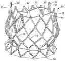
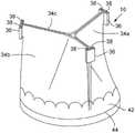
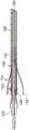
图1是根据一个实施例可用于替换心脏的自体主动脉瓣膜的假体瓣膜的透视图。1 is a perspective view of a prosthetic valve that may be used to replace a native aortic valve of a heart, according to one embodiment.
图2是图1的假体瓣膜的一部分的透视图,其示出了两个小叶到假体瓣膜的支撑框架的连接。2 is a perspective view of a portion of the prosthetic valve of FIG. 1 showing the connection of the two leaflets to the support frame of the prosthetic valve.
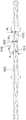
图3是图1的假体瓣膜的支撑框架的侧面正视图。FIG. 3 is a side elevational view of the support frame of the prosthetic valve of FIG. 1 .
图4是图1的假体瓣膜的支撑框架的透视图。FIG. 4 is a perspective view of the support frame of the prosthetic valve of FIG. 1 .
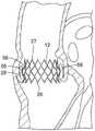
图5A是示出植入在主动脉环内的图1的假体瓣膜的心脏的横截面图。5A is a cross-sectional view of the heart showing the prosthetic valve of FIG. 1 implanted within the aortic annulus.
图5B是图5A的放大视图,其示出了植入在主动脉环内的假体瓣膜,为了清晰起见示出为移除了假体瓣膜的小叶结构。5B is an enlarged view of FIG. 5A showing the prosthetic valve implanted within the aortic annulus, shown with the leaflet structures of the prosthetic valve removed for clarity.
图6是示出为在固定到支撑框架之前的图1的假体瓣膜的小叶结构的透视图。6 is a perspective view of the leaflet structure of the prosthetic valve of FIG. 1 shown prior to being secured to a support frame.
图7是图1的假体瓣膜的横截面图。FIG. 7 is a cross-sectional view of the prosthetic valve of FIG. 1 .
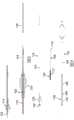
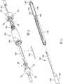
图8是可用于递送和植入例如图1中示出的假体瓣膜等假体瓣膜的递送设备的实施例的横截面图。图8A-8C是图8的横截面的放大横截面图。8 is a cross-sectional view of an embodiment of a delivery device that may be used to deliver and implant a prosthetic valve, such as the prosthetic valve shown in FIG. 1 . 8A-8C are enlarged cross-sectional views of the cross-section of FIG. 8 .
图9是图8的递送设备的分解视图。FIG. 9 is an exploded view of the delivery device of FIG. 8 .
图10是图8的递送设备的导引导管的侧视图。FIG. 10 is a side view of the guide catheter of the delivery device of FIG. 8 .
图11是图10的导引导管的近端部分的透视分解视图。FIG. 11 is a perspective exploded view of the proximal end portion of the guide catheter of FIG. 10 .
图12是图10的导引导管的远端部分的透视分解视图。FIG. 12 is a perspective exploded view of the distal end portion of the guide catheter of FIG. 10 .
图13是图8的递送设备的扭矩轴导管的侧视图。FIG. 13 is a side view of the torque shaft catheter of the delivery device of FIG. 8 .
图14是图13的扭矩轴导管的可旋转螺杆的放大侧视图。FIG. 14 is an enlarged side view of the rotatable screw of the torque shaft guide of FIG. 13 .
图15是设置于扭矩轴的端部处的耦接构件的放大的透视图。15 is an enlarged perspective view of a coupling member provided at the end of the torque shaft.
图16是图13的扭矩轴导管中使用的螺纹螺母的放大的透视图。FIG. 16 is an enlarged perspective view of a threaded nut used in the torque shaft guide of FIG. 13 .
图17是图8的递送设备的鼻锥导管的远端部分的放大的侧视图。17 is an enlarged side view of the distal portion of the nose cone catheter of the delivery device of FIG. 8 .
图17A是图17示出的导管的鼻锥的放大的横截面图。17A is an enlarged cross-sectional view of the nose cone of the catheter shown in FIG. 17 .
图17B是图8的递送设备的远端部分的放大横截面视图,其示出了以压缩状态保持于递送护套内的假体瓣膜的支架。17B is an enlarged cross-sectional view of the distal portion of the delivery device of FIG. 8 showing the stent of the prosthetic valve retained within the delivery sheath in a compressed state.
图18是图8的递送设备的远端部分的放大的侧视图,其示出了递送位置中的递送护套覆盖呈压缩状态的假体瓣膜以供递送到患者体内。18 is an enlarged side view of the distal portion of the delivery device of FIG. 8 showing the delivery sheath in the delivery position covering the prosthetic valve in a compressed state for delivery into a patient.
图19是图8的递送设备的远端部分的横截面的放大的横截面视图,其示出了将假体瓣膜的支架固定到递送设备的瓣膜保持机构。19 is an enlarged cross-sectional view of a cross-section of the distal portion of the delivery device of FIG. 8 showing the valve retention mechanism securing the stent of the prosthetic valve to the delivery device.
图20是类似于图19的放大的横截面视图,其示出了瓣膜保持机构的内叉处于释放位置以用于从递送设备释放假体瓣膜。Figure 20 is an enlarged cross-sectional view similar to Figure 19 showing the inner prong of the valve retention mechanism in a released position for releasing the prosthetic valve from the delivery device.
图21和图22是图8的递送设备的远端部分的放大的侧视图,其示出了用于从递送护套展开假体瓣膜的扭矩轴的操作。Figures 21 and 22 are enlarged side views of the distal portion of the delivery device of Figure 8 illustrating the operation of the torque shaft for deploying the prosthetic valve from the delivery sheath.
图23-26是可用于操作图8中示出的递送设备的扭矩轴的机动递送设备的实施例的各个图示。23-26 are various illustrations of embodiments of motorized delivery devices that may be used to operate the torque shaft of the delivery device shown in FIG. 8 .
图27是可用于操作图8中示出的递送设备的扭矩轴的可替代的马达的透视图。FIG. 27 is a perspective view of an alternative motor that may be used to operate the torque shaft of the delivery device shown in FIG. 8 .
图28A是图10的导引导管轴的远侧区段的放大视图。28A is an enlarged view of a distal section of the guide catheter shaft of FIG. 10 .
图28B示出了用于例如通过对金属管进行激光切割来形成图28A中示出的轴的所述部分的切割图案。Figure 28B shows a cutting pattern used to form the portion of the shaft shown in Figure 28A, eg, by laser cutting a metal tube.
图29A是根据另一实施例的导引导管轴的远侧区段的放大视图。29A is an enlarged view of a distal section of a guide catheter shaft according to another embodiment.
图29B示出了用于例如通过对金属管进行激光切割来形成图29A的轴的切割图案。Figure 29B shows a cut pattern for forming the shaft of Figure 29A, eg, by laser cutting a metal tube.
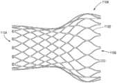
图30是用于在假体瓣膜中使用的支撑支架的侧面正视图。Figure 30 is a side elevational view of a support stent for use in a prosthetic valve.
图31是从递送筒部分地展开的假体心脏瓣膜的框架的侧面正视图。Figure 31 is a side elevational view of the frame of the prosthetic heart valve partially deployed from the delivery barrel.
图32-35是假体心脏瓣膜的远端部分的透视图,其从递送筒部分地展开并且随着假体心脏瓣膜缩回到递送筒中而反转。32-35 are perspective views of a distal portion of a prosthetic heart valve partially deployed from a delivery barrel and inverted as the prosthetic heart valve is retracted into the delivery barrel.
图36是根据另一实施例的用于假体心脏瓣膜的框架的侧面正视图。36 is a side elevational view of a frame for a prosthetic heart valve according to another embodiment.
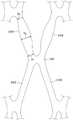
图37是图36的框架的支柱行的一部分的放大图。FIG. 37 is an enlarged view of a portion of a column row of the frame of FIG. 36 .
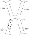
图38是图36的框架的两个支柱行之间的接合部的侧面正视图。38 is a side elevational view of the junction between two strut rows of the frame of FIG. 36 .
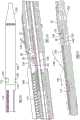
图39是从递送筒部分地展开的图36的框架的侧面正视图。Figure 39 is a side elevational view of the frame of Figure 36 partially deployed from the delivery cartridge.
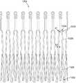
图40是图36的框架的侧面正视图,其示出指定的设计直径下的框架的总长度Y。Figure 40 is a side elevational view of the frame of Figure 36 showing the overall length Y of the frame at the specified design diameter.
图41是示出作为图36的框架的直径的函数的径向力的曲线图。FIG. 41 is a graph showing radial force as a function of diameter of the frame of FIG. 36 .
图42-44是示出在无折叠的情况下图36的框架的再捕获的顶部透视图。42-44 are top perspective views showing recapture of the frame of FIG. 36 without folding.
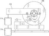
图45是根据一个实施例的径向膨胀力计量设备的透视图。45 is a perspective view of a radial expansion force metering device according to one embodiment.
图46是附接了校准轭和重块的图45的设备的后端视图。Figure 46 is a rear end view of the apparatus of Figure 45 with the alignment yoke and weight attached.
图47A-51示出了根据一个实施例被配置成接收假体心脏瓣膜的自膨式对接台的实施例。47A-51 illustrate an embodiment of a self-expanding docking station configured to receive a prosthetic heart valve, according to one embodiment.
图52-53B示出被配置成接收假体心脏瓣膜的自膨式对接台的另一实施例。52-53B illustrate another embodiment of a self-expanding docking station configured to receive a prosthetic heart valve.
图54和55示出自膨式假体心脏瓣膜的另一实施例。54 and 55 illustrate another embodiment of a self-expanding prosthetic heart valve.
图56示出自膨式假体心脏瓣膜的另一实施例。Figure 56 shows another embodiment of a self-expanding prosthetic heart valve.
图57示出根据另一实施例的图36的框架的两个支柱行之间的接合部的一部分。Figure 57 shows a portion of a junction between two strut rows of the frame of Figure 36 according to another embodiment.
图58和59示出根据另一实施例的图36的框架的两个支柱行之间的接合部的一部分。Figures 58 and 59 illustrate a portion of the junction between two strut rows of the frame of Figure 36 according to another embodiment.
图60是根据另一实施例被配置成接收假体心脏瓣膜的自膨式对接台的框架的侧面正视图。60 is a side elevational view of a frame of a self-expanding docking station configured to receive a prosthetic heart valve according to another embodiment.
图61是被配置成用于植入在自体二尖瓣瓣膜中的假体心脏瓣膜的另一实施例的透视图。61 is a perspective view of another embodiment of a prosthetic heart valve configured for implantation in a native mitral valve valve.
图62是根据一个实施例的图61的假体心脏瓣膜的内部框架的透视图。Figure 62 is a perspective view of the inner frame of the prosthetic heart valve of Figure 61, according to one embodiment.
图63是根据一个实施例的图61的假体心脏瓣膜的外部框架的透视图。63 is a perspective view of an outer frame of the prosthetic heart valve of FIG. 61, according to one embodiment.
图64示出处于放平配置中的图61的假体心脏瓣膜的外部框架。Figure 64 shows the outer frame of the prosthetic heart valve of Figure 61 in a flattened configuration.
具体实施方式Detailed ways
本文描述了用于假体植入物的具有不同支柱宽度、厚度、接合部宽度和/或其它参数的自膨式框架的实施例,其被配置成减少或防止在再捕获期间框架折叠到递送设备的递送筒/护套中。举例来说,在某些实施例中,本文中所描述的框架的支柱可包括在相邻支柱之间的接合部处或附近的支柱宽度,该支柱宽度小于支柱的中心附近的支柱宽度。在某些实施例中,接合部处或附近的支柱宽度与支柱的中间部分处的支柱宽度的比率处于特定范围内可降低框架的再捕获期间折叠的发生率。在某些实施例中,支柱可在其流入接合部处、其流出接合部处或两者处具有减小的支柱宽度。在某些实施例中,框架的流入端处的一行或多行支柱中的支柱可包括如本文所描述的不同的支柱宽度。在某些实施例中,如本文所描述的改变支柱宽度可将部分地展开的框架的流入直径与递送筒的内径的比率维持在规定范围内以便减少折叠。举例来说,本文中所描述的特定的框架实施例可允许框架的总长度的80%或更多从递送筒露出,并且接着再捕获到递送筒中,而无折叠。在某些示例中,这可降低植入物可能在手术中途被损坏且需要替换的风险,借此缩短手术时间并改进患者治疗成效。Described herein are embodiments of self-expanding frames with different strut widths, thicknesses, joint widths, and/or other parameters for prosthetic implants that are configured to reduce or prevent frame collapse to delivery during recapture In the delivery barrel/sheath of the device. For example, in certain embodiments, the struts of the frames described herein may include strut widths at or near the junctions between adjacent struts that are less than strut widths near the center of the struts. In certain embodiments, having the ratio of the strut width at or near the junction to the strut width at the mid-portion of the strut within a certain range may reduce the incidence of folding during recapture of the frame. In certain embodiments, struts may have reduced strut widths at their inflow junctions, their outflow junctions, or both. In certain embodiments, the struts in one or more rows of struts at the inflow end of the frame may include different strut widths as described herein. In certain embodiments, varying the strut width as described herein may maintain the ratio of the inflow diameter of the partially deployed frame to the inner diameter of the delivery barrel within a specified range in order to reduce folding. For example, certain frame embodiments described herein may allow 80% or more of the overall length of the frame to be exposed from the delivery barrel and then recaptured into the delivery barrel without folding. In some instances, this can reduce the risk that the implant may be damaged mid-operatively and need to be replaced, thereby reducing operative time and improving patient outcomes.
第一代表性实施例First representative embodiment
首先参看图1,示出了根据一个实施例的假体主动脉心脏瓣膜10。假体瓣膜10包含支撑柔性小叶节段14的可膨胀框架部件或支架12。假体瓣膜10可径向压缩到压缩状态以供递送穿过身体到达展开位点,并且在展开位点处可膨胀到图1中示出的其功能大小。在某些实施例中,假体瓣膜10为自膨式;也就是说,假体瓣膜在从递送护套的远端前进时可径向膨胀到其功能大小。下文详细描述了尤其适合于经皮递送和植入自膨式假体瓣膜的设备。在其它实施例中,假体瓣膜可以是球囊可膨胀假体瓣膜,其可适于以压缩状态安装于递送导管的球囊上。如本领域已知的,可通过使球囊充气而在展开位点处使假体瓣膜膨胀到其功能大小。Referring first to FIG. 1, a prosthetic
所示出的假体瓣膜10适于在自体主动脉环中展开,但其还可用于替换心脏的其它自体瓣膜。此外,假体瓣膜10可适于替换身体内的其它瓣膜,此类静脉瓣膜。The illustrated
图3和图4出于说明的目的示出了无小叶节段14的支架12。如所示,支架12可由多个纵向延伸的大体正弦形框架构件或支柱16形成。支柱16形成有交替的弯曲部,并且在由相邻弯曲部的顶点形成的节点18处彼此焊接或以其它方式固定以便形成网状物结构。支柱16可由例如被称为镍钛诺的镍钛合金等合适的形状记忆材料组成,其允许假体瓣膜被压缩到减小的直径以供在递送设备(例如下文描述)中递送,并且接着当从递送设备展开时致使假体瓣膜在患者身体内膨胀到其功能大小。如果假体瓣膜是适于卷曲到递送设备的可充气球囊上并且通过对球囊充气而膨胀到其功能大小的球囊可膨胀假体瓣膜,则支架12可由例如镍-铬合金或不锈钢等合适的延性材料组成。3 and 4
支架12具有流入端26和流出端27。由支柱16形成的网状物结构包括大体圆柱形“上部”或流出端部分分20、朝外弯曲或扩张的中间节段22,以及朝内弯曲的“下部”或流入端部分分24。中间节段22的大小和形状被期望设置为以延伸到主动脉根部中的瓦尔萨尔瓦氏窦(Valsalva sinuses)中,以便一旦植入就辅助将假体瓣膜锚定在适当位置。如所示,网状物结构期望沿着其全长具有弯曲形状,其直径从流出端部分分20向中间节段22逐步地增加,接着从中间节段22向流入端部分分24上的某一位置逐步地减小,并且接着直径逐步地增加以形成终止于流入端26处的张开部分。The
当假体瓣膜处于其膨胀状态时,中间节段22具有直径D1,流入端部分分24具有最小直径D2,流入端26具有直径D3,并且流出端部分分20具有直径D4,其中D2小于D1和D3,并且D4小于D2。此外,D1和D3期望大于其中将植入假体瓣膜的自体环的直径。以此方式,支架12的整体形状辅助将假体瓣膜保持在植入位点处。更确切地说,并且参看图5A和图5B,假体瓣膜10可植入在自体瓣膜(在所说明的示例中,主动脉瓣膜)内,使得下部节段24被定位在主动脉环28内,中间节段24在主动脉环上方延伸到瓦尔萨尔瓦氏窦56中,并且下部张开端26在主动脉环下方延伸。假体瓣膜10通过抵着主动脉环28的周围组织以及支架的几何结构的下部节段24的径向向外力而保持在自体瓣膜内。确切地说,中间节段24和张开的下端26径向朝外延伸超出主动脉环28以更好地抵抗上游和下游方向(朝向和背离主动脉)中假体瓣膜的轴向移位。取决于自体小叶58的状况,假体瓣膜通常在自体环28内展开,自体小叶58向上折叠并且压缩在支架12的外表面和瓦尔萨尔瓦氏窦的壁之间,如图5B中所描绘的。在某些情况下,可能期望在植入假体瓣膜10之前切除小叶58。When the prosthetic valve is in its expanded state, the
具有自膨式框架的已知假体瓣膜通常具有延伸到脉管的非患病区域中且固定到非患病区域的额外锚定装置或框架部分。因为支架12的形状辅助保持假体瓣膜,所以不需要额外的锚定装置,并且支架的总长度L可被最小化以防止支架上部部分20延伸到主动脉的非患病区域中,或至少使上部部分20延伸到主动脉的非患病区域中的范围最小化。避开患者的脉管的非患病区域有助于在需要将来干预性治疗的情况下避免并发症。举例来说,假体瓣膜可更容易地从患者移除,因为支架主要锚定到自体瓣膜的患病部分。此外,在某些实施例中,较短的假体瓣膜可更容易地在主动脉弓周围导航。Known prosthetic valves with self-expanding frames typically have additional anchoring devices or frame portions that extend into and secure to non-diseased areas of the vessel. Because the shape of the
在特定实施例中,针对既定在22-mm到24-mm环中使用的假体瓣膜,直径D1为约28mm到约32mm,其中30mm为特定示例;直径D2为约24mm到约28mm,其中26mm为特定示例;直径D3为约28mm到约32mm,其中30mm为特定示例;并且直径D4为约24mm到约28mm,其中26mm为特定示例。在特定实施例中,长度L为约20mm到约24mm,其中22mm为特定示例。In certain embodiments, for prosthetic valves intended for use in 22-mm to 24-mm rings, diameter D1 is about 28 mm to about 32 mm, with 30 mm being a specific example; diameter D2 is about 24 mm to about 28 mm, with 26 mm are specific examples; diameter D3 is about 28 mm to about 32 mm, with 30 mm being a specific example; and diameter D4 is about 24 mm to about 28 mm, with 26 mm being a specific example. In certain embodiments, the length L is about 20 mm to about 24 mm, with 22 mm being a specific example.
参看图1,支架12可具有从支架上部部分20延伸的多个成角度间隔的保持臂或凸起,具有柱30(在所说明的实施例中,为三个)的形式。每个保持臂30具有相应的孔隙32,所述孔隙的大小被设置为接收可用于形成假体瓣膜和递送设备之间的可释放连接(下文描述)的瓣膜保持机构的叉头。在可替代实施例中,如果未使用瓣膜保持机构,则不必提供保持臂30。1, the
如图6和图7中最佳示出的,在所说明的实施例中,小叶组件14包括由柔性材料组成的三个小叶34a、34b、34c。每个小叶具有流入端部分分60和流出端部分分62。小叶可包括任何合适的生物材料(例如,心包组织,例如牛或马心包)、生物相容性合成材料,或例如以引用的方式并入本文中的第6,730,118号美国专利中描述的其它此类材料。小叶组件14可包含环形加固裙套42,其在邻近假体瓣膜的流入端的缝合线44处固定到小叶34a、34b、34c的流入端部分分的外表面。通过将裙套42缝合到支架的下部节段24的支柱16,可以将小叶组件14的流入端部分分固定到支架12(图1中最佳示出)。如图7所示,小叶组件14可进一步包含固定到小叶的流入端部分分60的内表面的内部加固条带46。As best shown in Figures 6 and 7, in the illustrated embodiment, the
参看图1和图2,小叶组件14的流出端部分分可在小叶34a、34b、34c的三个成角度间隔的连合附接部处固定到支架12的上部部分。如图2中最佳示出的,通过在一对小叶所形成的连合处将加固节段36缠绕在所述两个小叶的邻近上边缘部分38周围,并且用缝合线48将加固节段36固定到边缘部分38,可以形成每个连合附接部。接着可用缝合线50在支架的流出端附近将加固材料和小叶的包夹层固定到支架12的支柱16。因此,小叶被期望从流入端26向流出端27延伸支架的全长或大致全长。加固节段36加固小叶到支架的附接部以便使缝合线处的应力集中最小化,并且避免小叶的在使用期间挠曲的部分上的“针孔”。加固节段36、裙套42和内部加固条带46期望由例如聚四氟乙烯(PTFE)等生物相容性合成材料或例如编织聚酯(例如,聚对苯二甲酸乙二醇酯)(PET))等编织物材料组成。1 and 2, the outflow end portion of the
图7示出假体瓣膜10的操作。在心脏舒张期间,小叶34a、34b、34c塌缩以有效地闭合假体瓣膜。如所示出的,支架12的中间节段22的弯曲形状限定中间节段和小叶之间的模仿瓦尔萨尔瓦氏窦的空间。因此,当小叶闭合时,进入“窦”的回流沿着小叶的上表面形成血液紊流,如由箭头52所指示的。此紊流辅助清洗小叶和裙套42以使凝块形成最小化。FIG. 7 illustrates the operation of the
假体瓣膜10可以逆行方法植入,其中以卷曲状态安装在递送设备的远端处的假体瓣膜经由股动脉被引入到身体内并且推进穿过主动脉弓到达心脏,如以引用的方式并入本文中的第2008/0065011号美国专利公开中进一步描述的。The
图8和图9示出根据一个实施例的递送设备100,其可用于递送例如上文描述的假体瓣膜10等自膨式假体瓣膜穿过患者的脉管。递送设备100包括具有伸长轴104的第一最外或主导管102(在图10中单独示出),所述伸长轴的远端耦接到递送护套106(图18;也称为递送筒)。主导管102的近端连接到递送设备的手柄。图23-26示出具有用于操作递送设备的电动机的手柄机构的实施例。手柄机构在下文中详细描述。在假体瓣膜的递送期间,手柄可由外科医生使用以穿过患者的脉管推进和缩回递送设备。虽然不是必需的,但主导管102可包括导引导管,其被配置成随着其被推进穿过患者的脉管而允许外科医生导引或控制轴104的远侧部分的弯曲或挠曲量,例如如下文进一步描述的。导引导管的另一实施例在以引用的方式并入本文中的第2008/0065011号美国专利公开中公开。8 and 9 illustrate a
如图9中最佳示出的,递送设备100还包含第二中间导管108(在本文中也被称为扭矩轴导管),其具有伸长轴110(在本文中也被称为扭矩轴)和连接到轴110的远端的伸长螺杆112。中间导管108的轴110同轴地延伸穿过主导管102的轴104。递送设备100还可包含第三鼻锥导管118,其具有伸长轴120和固定到轴120的远端部分的鼻件或鼻锥122。鼻件122可具有如所示的渐缩外表面,以用于无创地跟踪穿过患者的脉管。鼻锥导管的轴120延伸穿过假体瓣膜10(图8-9中未示出)和中间导管108的轴110。在所说明的配置中,最内轴120被配置成可相对于轴104、110轴向以及可旋转地移动,并且扭矩轴110被配置成可相对于轴104、120旋转以实现假体瓣膜从递送设备进行瓣膜展开及释放,如在下文详细描述的。此外,最内轴120可具有用于接收导引线的管腔,使得递送设备可在患者的脉管内部在导引线上方推进(图8C)。As best shown in Figure 9, the
如图10中最佳示出的,外部导管102可包括在其近端处的挠曲控制机构168以随着其推进穿过患者的脉管而控制外轴104的远侧部分的弯曲或挠曲量,例如如下文进一步描述的。外轴104可包括从挠曲控制机构168延伸的近侧区段166和包括带槽金属管的远侧区段126,所述带槽金属管增加此位置处外轴的柔性。远侧区段126的远端部分可包括瓣膜保持机构114的外叉130,其被配置成在瓣膜递送期间将假体瓣膜10可释放地固定到递送设备100,如在下文详细描述的。As best shown in Figure 10, the
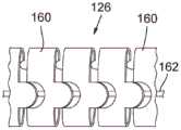
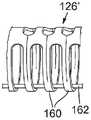
图28A是外轴104的远侧区段126的一部分的放大视图。图28B示出了切割图案,所述切割图案可用于通过在金属管中激光切割所述图案来形成远侧区段126。远侧区段126包括形成带槽金属管的多个互连的圆形带或连杆160。拉线162可定位在远侧区段126内部,并且可从远侧区段126的位置164延伸(图10和图12)到挠曲控制机构。拉线162的远端可在位置164处例如通过焊接固定到远侧区段126的内表面。拉线162的近端可以可操作地连接到挠曲控制机构168,所述挠曲控制机构被配置成将张力施加和释放到拉线以便控制轴的弯曲,如下文进一步描述的。轴的连杆160和相邻连杆之间的间隙的形状被设置为允许在拉线162上施加轻拉力后轴的弯曲。在所说明的实施例中,如图12中最佳展示的,远侧区段126固定到具有不同构造(例如,一层或多层聚合物管道)的近侧区段166。在所说明的实施例中,近侧区段166从挠曲控制机构168延伸到远侧区段126并且因此构成外轴104的长度的大部分。在可替代实施例中,外轴104的全长或大体上全长可由包括互连连杆160的一个或更多个节段的带槽金属管形成。在任何情况下,具有此构造的主轴的使用可允许递送设备被高度操控,尤其是在与具有图40和图41中展示的构造的扭矩轴组合使用时(下文描述)。FIG. 28A is an enlarged view of a portion of the
连杆160的宽度可变化以改变沿着其长度的远侧区段的柔性。举例来说,带槽管件的远端部分内的连杆可相对较窄以增加所述位置处轴的柔性,而带槽管件的近端部分内的连杆可相对较宽,使得轴在所述位置处的柔性相对较小。The width of the
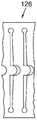
图29A展示了可例如通过对金属管进行激光切割而形成的由126'指示的远侧区段的可替代实施例。区段126'可包括递送设备(如图12所示)的外轴的远侧区段,或外轴的大体全长可具有图29A中展示的构造。图29B展示了用于形成区段126'的切割图案。在另一实施例中,递送设备可包含复合外轴,其包括与熔融在金属层中的间隙内的聚合物外层层压的激光切割的金属管。在一个示例中,复合轴可包括具有图29A和图29B的切割图案的激光切割的金属管,以及熔融在金属管的连杆160之间的间隙中的聚合物外层。在另一示例中,复合轴可包括具有图28A和图28B的切割图案的激光切割的金属管,以及熔融在金属管的连杆160之间的间隙中的聚合物外层。复合轴还可包含熔融在金属管的连杆160之间的间隙中的聚合物内层。Figure 29A shows an alternative embodiment of the distal section indicated by 126' that may be formed, for example, by laser cutting a metal tube. Section 126' may comprise the distal section of the outer shaft of the delivery device (shown in Figure 12), or the substantially full length of the outer shaft may have the configuration shown in Figure 29A. Figure 29B shows the cutting pattern used to form the segment 126'. In another embodiment, the delivery device may comprise a composite outer shaft comprising a laser cut metal tube laminated with a polymeric outer layer fused within a gap in the metal layer. In one example, the composite shaft may comprise a laser cut metal tube having the cutting pattern of FIGS. 29A and 29B , and a polymer outer layer fused in the gaps between the connecting
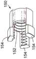
参看图8A和图11,挠曲控制机构168可包括容纳安装在轨192/190上的滑动螺母188的可旋转壳体或手柄部分186。通过一个或更多个杆192防止滑动螺母188在壳体内旋转,所述杆中的每一个杆均部分安置于轨192内的相应凹部中以及螺母188的内侧上的槽或凹部中。拉线162的近端固定到螺母188。螺母188具有啮合壳体的内螺纹的外螺纹。因此,旋转壳体186会致使螺母188在壳体内在近侧或远侧方向中轴向移动,这取决于壳体的旋转方向。在第一方向上(例如,顺时针)旋转壳体致使螺母在近侧方向中行进,这向拉线162施加张力,从而致使递送设备的远端弯曲或挠曲。在第二方向上(例如,逆时针)旋转壳体致使螺母在远侧方向中行进,这减轻了拉线162中的张力且允许递送设备的远端在其自身的弹性下挠曲回到其挠曲前的配置。8A and 11, the
如图13中最佳展示的,扭矩轴导管108包含邻近螺杆112安装在扭矩轴110的远端部分上的具有环128(也称为锚定盘)的形式的环形凸起。环128被固定到扭矩轴110的外表面,使得其无法相对于扭矩轴轴向或旋转移动。外轴104的内表面形成有例如槽或凹部等特征,其接收环128使得环和外轴104的内表面上的对应特征允许扭矩轴110相对于外轴104旋转,但防止扭矩轴相对于外轴轴向移动。外轴104上的接收环128的对应特征可以是形成于远侧区段126中的朝内延伸的凸台部分,例如图12中164处所展示的。在所说明的实施例中(如图14中最佳展示的),环128是螺杆112的一体式部分(即,螺杆112和环128是单个部件的多个部分)。可替换地,螺杆112和环是固定地固定到扭矩轴110的远端的分开形成的部件。As best shown in FIG. 13 , the torque
扭矩轴110期望被配置成可相对于递送护套106旋转以实现假体瓣膜10从递送护套106递增地且受控地推进。为此,并且根据一个实施例,递送设备100可包含安装在螺杆112的外螺纹上的具有螺纹螺母150的形式的护套保持环。如图16中最佳展示的,螺母150包含啮合螺杆的外螺纹的内螺纹152和轴向延伸的支腿154。每个支腿154具有隆起的远端部分,其延伸到护套106的近端中的开口172中和/或与开口172形成搭扣配合连接(如图18中最佳展示的)以便将护套106固定到螺母150。如图17B和图18中所示出的,护套106在假体瓣膜10上方延伸并且将假体瓣膜保持在径向压缩状态,直至使用者缩回护套106以展开假体瓣膜。The
如图21和图22中最佳展示的,瓣膜保持机构的外叉130包括多个叉头134,其中的每个延伸穿过限定在螺母的两个相邻支腿154之间的区域,以便防止在螺杆旋转后螺母相对于螺杆112旋转。如此,扭矩轴110(并且因此螺杆112)的旋转致使螺母150相应地进行轴向移动。螺母150和护套106之间的连接被配置成使得螺母沿着螺杆112(在远侧或近侧方向中)轴向移动会致使护套106相对于螺杆和瓣膜保持机构在相同的方向上轴向移动。图21展示了远侧位置中的螺母150,其中护套106(图21中未图示)在假体瓣膜10上方延伸且将假体瓣膜10保持在压缩状态以供递送。螺母150从远侧位置(图21)到近侧位置(图22)的移动致使护套106在近侧方向中移动,借此从护套106展开假体瓣膜。可通过机动机构(例如图23-26中展示和下文描述)或通过手动地转动曲柄或轮子来实现用以实施护套106的轴向移动的扭矩轴110的旋转。As best shown in FIGS. 21 and 22, the
图17展示了固定到最内轴120的远端的鼻锥122的放大视图。在所说明的实施例中,鼻锥122包含大小被设置为适配在护套106的远端内部的近端部分174。鼻锥的中间节段176在使用中紧邻护套的端部定位,并且形成有多个纵向凹槽或凹入部分178。中间节段176在其近端180处的直径期望稍微大于护套106的外径。近端180可保持与护套106的远端紧密接触以防止周围组织接触护套的金属边缘。凹槽178允许中间节段随着递送设备被推进穿过导入器护套而被径向压缩。这允许鼻锥的大小稍微超过导入器护套的内径。图17B展示了鼻锥122和递送位置中的护套106的横截面,其中假体瓣膜以压缩递送状态保持在护套106内部(出于说明的目的,仅展示假体瓣膜的支架12)。如所展示的,中间节段176的近端180可与护套106的远端对接,且鼻锥的渐缩近侧表面182可在支架12的远侧部分内延伸。FIG. 17 shows an enlarged view of the
如上所述,递送设备100可包含用于可释放地保持假体瓣膜的支架12的瓣膜保持机构114(图8B)。瓣膜保持机构114可包含呈外叉130的形式的第一瓣膜固定部件(如图12中最佳展示的)(也称为“外三叉戟”或“释放三叉戟”),以及呈内叉132的形式的第二瓣膜固定部件(如图17中最佳展示的)(也称为“内三叉戟”或“锁定三叉戟”)。外叉130与内叉132协作以与支架12的保持臂30形成可释放连接。As described above,
外叉130的近端连接到外轴104的远侧区段126,并且外叉的远端可释放地连接到支架12。在所说明的实施例中,外叉130和远侧区段126可一体成型为单个部件(例如,外叉和远侧区段可由单件金属管进行激光切割或以其它方式机械加工而成),但这些部件可分开形成且随后彼此连接。内叉132可安装在鼻导管轴120上(如图17中最佳展示的)。内叉132将支架连接到鼻导管轴120的远端部分。鼻导管轴120可相对于外轴104轴向移动以从瓣膜保持机构释放假体瓣膜,如下文进一步描述的。The proximal end of the
如图12中最佳展示的,外叉130包含对应于支架12的保持臂30的多个成角度间隔的叉头134(在所说明的实施例中为三个),所述叉头从远侧区段126的远端延伸。每个叉头134的远端部分包含相应开口140。如图17中最佳展示的,内叉132包含对应于支架12的保持臂30的多个成角度间隔的叉头136(在所说明的实施例中为三个),所述叉头从内叉的近端处的基底部分138延伸。内叉的基底部分138固定地固定到鼻导管轴120(例如,利用合适的粘合剂)以防止内叉相对于鼻导管轴120进行轴向和旋转移动。As best shown in FIG. 12 , the
外叉的每个叉头与内叉的相应叉头协作以与支架的保持臂30形成可释放连接。在所说明的实施例中,举例来说,每个叉头134的远端部分形成有开口140。当假体瓣膜固定到递送设备时(如图19中最佳展示),支架12的每个保持臂30朝内延伸穿过外叉的叉头134的开口140,并且内叉的叉头136插入穿过保持臂30的开口32以便保持保持臂30后退离开开口140。图42还展示了在假体瓣膜被加载到护套106中之前通过内叉和外叉固定到递送设备的假体瓣膜10。向近侧(在图20中,在箭头184的方向上)缩回内叉头136以从开口32移除叉头可有效地从保持机构释放假体瓣膜10。当内叉132移动到近侧位置时(图20),支架的保持臂30可在支架的弹性下从外叉130中的开口140径向朝外移动。以此方式,瓣膜保持机构114与假体瓣膜形成可释放连接,所述可释放连接足够牢固以相对于递送设备保持假体瓣膜,从而允许使用者在假体瓣膜从递送护套展开之后微调或调整假体瓣膜的位置。当假体瓣膜被定位于期望的植入位点处时,可通过相对于外轴104缩回鼻导管轴120(从而相对于外叉130缩回内叉132)来释放假体瓣膜和保持机构之间的连接。Each prong of the outer fork cooperates with a corresponding prong of the inner fork to form a releasable connection with the retaining
下文描述用于将假体瓣膜10压缩和装载到护套106中的技术。一旦假体瓣膜10已装载于递送护套106中,则递送设备100可插入到患者身体内以供递送假体瓣膜。在一个方法中,可以逆行程序递送假体瓣膜,其中递送设备插入到股动脉中并且推进穿过患者的脉管到达心脏。在插入递送设备之前,导入器护套可插入到股动脉中,然后是导引线,导引线经由主动脉推进穿过患者的脉管并进入左心室。递送设备100可接着插入穿过导入器护套且在导引线上方推进直至递送设备的包含假体瓣膜10的远端部分被推进到邻近于自体主动脉瓣膜或在自体主动脉瓣膜内的位置。Techniques for compressing and loading the
随后,可通过相对于外轴104旋转扭矩轴110而使假体瓣膜10从递送设备100展开。如下文所描述的,扭矩轴110的近端可以可操作地连接到可手动旋转的手柄部分或机动机构,从而允许外科医生实现扭矩轴110相对于外轴104的旋转。扭矩轴110和螺杆112的旋转致使螺母150和护套106在近侧方向中朝向外轴移动(图22),从而从护套展开假体瓣膜。随着假体瓣膜从递送护套的开口远端推进且开始膨胀,扭矩轴110的旋转致使护套以精确且受控的方式相对于假体瓣膜移动。因此,不同于已知递送设备,随着假体瓣膜开始从递送护套推进且膨胀,假体瓣膜保持抵抗由于假体瓣膜抵着护套的远端的膨胀力所导致的从护套不受控制的移动。此外,随着缩回护套106,假体瓣膜10借助于瓣膜保持机构114相对于内轴120和外轴104的端部保持在固定位置。如此,假体瓣膜10可随着缩回护套而相对于身体内的目标位置保持静止。此外,在假体瓣膜从护套部分推进之后,可能期望使假体瓣膜缩回到护套中,例如以重新定位假体瓣膜或从身体完全撤回假体瓣膜。可通过使扭矩轴的旋转逆向而使部分地展开的假体瓣膜缩回到护套中,这使得护套106在远侧方向中在假体瓣膜上方往回推进。Subsequently, the
在已知递送装置中,外科医生必须将推拉力施加到轴和/或护套来露出假体瓣膜。因此,难以在不使轴变形(例如,轴向压缩或拉伸轴)的情况下将力传送到装置的远端,轴变形继而会致使在露出过程期间假体瓣膜不受控制地移动。为了缓解此效应,可使轴杆和/或护套较刚性,这是不期望的,因为装置变得更难转向穿过脉管。相比而言,上文描述的使假体瓣膜露出的方式避免了如已知装置中要求的那样在轴上施加推拉力,使得相对高且准确的力可施加到轴的远端,而不损害装置的柔性。在某些实施例中,多达20磅的力可传送到扭矩轴的端部,而不会不利地影响露出过程。相比而言,利用推拉机构的现有技术的装置在露出过程期间通常无法超过约5磅的力。In known delivery devices, the surgeon must apply a push-pull force to the shaft and/or sheath to expose the prosthetic valve. Thus, it is difficult to transmit force to the distal end of the device without deforming the shaft (eg, axially compressing or stretching the shaft), which in turn can cause uncontrolled movement of the prosthetic valve during the exposure process. To mitigate this effect, the shaft and/or sheath can be made more rigid, which is undesirable as the device becomes more difficult to steer through the vessel. In contrast, the above-described manner of exposing the prosthetic valve avoids the application of push-pull forces on the shaft as required in known devices, allowing relatively high and accurate forces to be applied to the distal end of the shaft without Impair the flexibility of the device. In certain embodiments, up to 20 pounds of force can be transmitted to the end of the torque shaft without adversely affecting the exposure process. In contrast, prior art devices utilizing push-pull mechanisms typically cannot exceed about 5 pounds of force during the exposure process.
在假体瓣膜10从递送护套推进且膨胀到其功能大小之后(以引用的方式并入本文中的第9,867,700号美国专利的图42中描绘了固定到递送设备的膨胀的假体瓣膜10),假体瓣膜经由保持机构114保持连接到递送设备。因此,在假体瓣膜从递送护套推进之后,外科医生可例如通过在近侧和远侧方向中或左右来回地移动递送设备或者旋转递送设备(这致使假体瓣膜相应地移动)来相对于自体瓣膜中的期望的植入位置来重新定位假体瓣膜。保持机构114期望提供假体瓣膜和递送设备之间的连接,所述连接足够牢固且刚性以随着相对于自体瓣膜中的期望植入位置调整假体瓣膜的位置,抵抗血液的流动保持假体瓣膜相对于递送设备的位置。一旦外科医生将假体瓣膜定位在自体瓣膜中的期望的植入位置处,则可通过在近侧方向中相对于外轴104缩回最内轴120来释放假体瓣膜和递送设备之间的连接,在近侧方向中相对于外轴104缩回最内轴120可有效地缩回内叉132以从假体瓣膜的保持臂30中的开口32撤回其叉头136(图20)。稍微缩回外轴104允许外叉130后退离开假体瓣膜的保持臂30,所述保持臂朝外滑动穿过外叉中的开口140以使假体瓣膜与保持机构114完全断开连接。随后,递送设备可从身体撤回,从而保持假体主动脉瓣膜10植入在自体瓣膜内(例如图5A和5B中展示的)。After the
递送设备100在其远端处具有由相对刚性部件构成的半刚性区段,用于将扭矩轴的旋转转变为护套的轴向移动。确切地说,在所说明的实施例中,此半刚性区段包括假体瓣膜和螺杆112。递送设备100的优点在于,半刚性区段的总长度被最小化,因为使用螺母150而非外轴上的内螺纹来实现护套的平移。半刚性区段的减小的长度增加了沿着递送导管的远端部分的总体柔性。此外,半刚性区段的长度和位置保持恒定,因为扭矩轴不相对于外轴轴向平移。如此,递送导管的弯曲形状可在瓣膜展开期间得以维持,这改进了展开的稳定性。递送设备100的另一益处在于,环128防止轴向负载(压缩和张力)转移到扭矩轴110的在环的远侧的节段。The
在可替代的实施例中,递送设备可适于递送球囊可膨胀假体瓣膜。如上文所描述的,瓣膜保持机构114可用于将假体瓣膜固定到递送设备的端部。因为假体瓣膜的支架并非自膨式的,所以护套106可以是任选的。保持机构114增强了递送设备和假体瓣膜组件穿过导入器护套的可推动性。In an alternative embodiment, the delivery device may be adapted to deliver a balloon-expandable prosthetic valve. As described above, the
图23-26示出根据一个实施例的递送设备100的近端部分。递送设备100可包括手柄202,其被配置成可以按可释放方式连接到包括导管102、108、118的导管组件204的近端部分。出于各种原因可能期望将手柄202与导管组件204断开连接。举例来说,使手柄断开连接可允许另一装置在导管组件上方滑动,例如瓣膜撷取装置或辅助转向导管组件的装置。应注意,手柄202和导管组件204的特征中的任一个可实施于本文中所公开的递送设备的实施例中的任一个中。23-26 illustrate a proximal portion of a
图23和图24展示了导管组件204的近端部分部分地插入到手柄202的远侧开口中。主轴104的近端部分形成有环形凹槽212(如图24中最佳展示),其与手柄内部的固持机构或闩锁机构214协作。当导管组件的近端部分完全插入到手柄中时(如图25和图26中所展示的),固持机构214的啮合部分216至少部分延伸到凹槽212中。固持机构214的一侧连接到延伸穿过手柄的壳体的按钮218。固持机构214的相对侧由弹簧220接触,所述弹簧使固持机构偏置到凹槽212处啮合主轴104的位置。固持机构214在凹槽212内的啮合防止导管组件与手柄的轴向分离。可通过按压按钮218来从手柄释放导管组件,所述按钮使固持机构214从与主轴的锁定啮合移开。此外,主轴104可形成有凹槽212内的平坦表面部分。所述平坦表面部分抵着啮合部分216的相应平坦表面部分定位。随着扭矩轴在瓣膜展开期间旋转,此啮合保持主轴104相对于扭矩轴110静止。23 and 24 illustrate the proximal portion of the
扭矩轴110的近端部分可具有从动螺母222(图26),其可滑动地接收在安装于手柄内部的驱动筒224(图25)中。可通过将螺母222固定在耦接部件170上方(图15)而将螺母222固定到扭矩轴100的近端。图26是手柄202的内部的透视图,其中移除了驱动筒和其它组件以展示定位在驱动筒内的从动螺母和其它构件。筒224具有延伸筒的长度的贯通开口(或管腔),其成形为对应于螺母222的平面使得驱动筒的旋转可有效地旋转螺母222和扭矩轴110。驱动筒可具有可容纳一个或更多个密封件(例如,o型环246)的放大的远端部分236,所述一个或更多个密封件与主轴104的外表面形成密封(图25)。手柄还可容纳配件238,所述配件具有与扭矩轴的管腔和/或主轴的管腔连通的齐平端口。The proximal portion of the
驱动筒224经由齿轮228和230可操作地连接到电动机226。手柄还可容纳电池盒232,其包含用于为电动机226供电的电池。电动机在一个方向上的旋转致使扭矩轴110旋转,这继而致使护套106缩回且在导管组件的远端处露出假体瓣膜。电动机在相反方向中的旋转致使扭矩轴在相反方向中旋转,从而致使护套在假体瓣膜上方往回移动。手柄上的操作者按钮234允许使用者激活电动机,所述电动机可在任一方向中旋转以露出假体瓣膜或撷取膨胀或部分膨胀的假体瓣膜。
如上文所述,鼻导管轴120的远端部分可固定到内叉132,内叉132相对于外叉130移动以释放固定到递送设备的端部的假体瓣膜。轴120相对于主轴104(其固定外叉130)的移动可由可相对于主壳体244滑动的手柄的近端部分240实现。端部240可操作地连接到轴120,使得端部240的移动可有效地使轴120相对于主轴104轴向平移(从而致使假体瓣膜从内叉和外叉释放)。端部240可具有在手柄的相对侧上的柔性侧面板242,其通常在锁定位置中朝外偏置以相对于主壳体244保持端部。在假体瓣膜展开期间,使用者可按压侧面板242,所述侧面板从壳体中的对应特征脱离并且允许相对于主壳体向近侧拉动端部240,这致使轴120相对于主轴相应地轴向移动。轴120的近侧移动致使内叉132的叉头136从支架12中的孔隙32脱离,这继而允许支架的保持臂30从外叉130的叉头134中的开口140径向朝外偏转,借此释放假体瓣膜。As described above, the distal portion of the
图27示出了可用于驱动扭矩轴(例如,扭矩轴110)的由231指示的电动机的替代实施例。在此实施例中,导管组件可在无齿轮装置的情况下直接连接到电动机的轴233的一端。轴233包含管腔,其允许导管组件的最内轴(例如,轴120)、导引线和/或流体通过以便冲洗导管组件的管腔。Figure 27 shows an alternative embodiment of an electric motor, indicated at 231, that may be used to drive a torque shaft (eg, torque shaft 110). In this embodiment, the conduit assembly can be directly connected to one end of the shaft 233 of the motor without gearing. Shaft 233 contains a lumen that allows passage of the innermost shaft of the catheter assembly (eg, shaft 120), a guide wire, and/or fluid for flushing the lumen of the catheter assembly.
可替换地,用于旋转扭矩轴110的动力源可以是被配置成旋转扭矩轴的液压动力源(例如,液压泵)或气动(空气操作的)动力源。在另一实施例中,手柄可具有可操作为旋转扭矩轴110的可手动移动的操纵杆或轮子。Alternatively, the power source for rotating the
在另一实施例中,动力源(例如,电、液压或气动动力源)可以可操作地连接到轴,所述轴继而连接到假体瓣膜10。动力源被配置成使轴相对于瓣膜护套在远侧方向中以精确且受控的方式纵向往复运动,以便从护套推进假体瓣膜。可替换地,动力源可以可操作地连接到护套,以便使护套相对于假体瓣膜在近侧方向中纵向往复运动以从护套展开假体瓣膜。In another embodiment, a power source (eg, an electrical, hydraulic or pneumatic power source) may be operably connected to the shaft, which in turn is connected to the
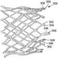
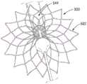
图30示出了用于在假体心脏瓣膜中使用的另一示例性支架300。出于说明的目的,仅示出了裸支架300,而省略了假体瓣膜的包含小叶和裙套的其它部件。然而,在使用中,假体瓣膜可包含安装到支架300的小叶34a、34b、34c和裙套42,如上文结合假体瓣膜10所描述的。支架300可具有与上文描述的假体瓣膜10的支架12相同的整体形状和配置,除了支架300的流出端处的所有顶点302均具有相应孔隙304以外。支架300可进一步包括也在流出端处的具有孔眼308的三个连合柱306(其在本文中也是“顶点”)。递送设备可通过在支架的一端(例如,流出端)处将缝合线线圈缠绕在顶点周围来啮合支架。在一些实施例中,支架可具有形成于顶点中或顶点附近的缺口、沟道或其它变窄部分,用于抵着其相应顶点稳定地固持缝合线线圈。框架300可被配置成用于使用本文中所描述的递送设备中的任一个进行递送。可用于递送支架300的递送设备的额外实施例在以引用的方式并入上文的第9,867,700号美国专利中以及以引用的方式并入本文中的第2015/0305867号美国专利申请公开案中描述。FIG. 30 shows another
第二代表性实施例Second representative embodiment
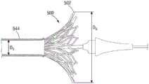
在例如假体瓣膜10等自膨式假体心脏瓣膜的展开期间,假体瓣膜可在外科医生评估假体瓣膜的放置时从递送筒部分地展开或露出。如果需要重新定位假体瓣膜,则假体瓣膜可部分或完全撤回到递送筒中或被“再捕获”以便将假体瓣膜重新定位在自体环中。取决于包含假体瓣膜的直径、递送筒的直径、在尝试再捕获之前假体瓣膜的总长度在递送筒外部的比例、尝试再捕获的次数等因素,假体心脏瓣膜的框架可能在再捕获时未能均匀地再塌缩为大体柱形形状。During deployment of a self-expanding prosthetic heart valve, such as
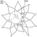
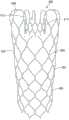
例如,图31示出从递送筒402部分地展开的自膨式假体瓣膜框架400。在图31中,已露出框架的总长度的约80%,留下框架长度的20%在递送筒402内。图32-35示出在从递送筒部分(例如,80%)展开之后框架400的再捕获。在图31和图32中,框架的流入端404形成从递送筒402向远侧延伸的张开或锥体形状。在图32中,框架的流入端404具有圆形或大体圆形形状。举例来说,在所说明的配置中,相邻支柱406可在相邻支柱406相交的接合部处形成多个流入顶点408。在图32中示出的状态中,如一对直径相对顶点408之间测量的距离或直径对于流入端404的圆周或周界周围的任何直径相对的顶点对可以是恒定或大体上恒定的。For example, FIG. 31 shows a self-expanding
随着框架撤回到递送筒中或被“重新包覆”,流入端期望应维持圆形或大体上圆形廓线,其中如流入端的圆周周围的每个顶点408处测量的直径为恒定或大体上恒定的。然而,在某些例子中,随着框架撤回到递送筒402中,一个或更多个支柱可径向朝内朝向框架的纵向轴线弯曲、变形、屈曲或折叠。图33中示出此现象,其中流入端404的右下象限中的一个或更多个支柱开始变形,并且流入端失去其圆形或大体圆形形状。在图34中,变形进一步发展,并且流入顶点408A已经径向朝内朝向导引线410偏离。在图35中,先前位于图32-34的右下象限中的一个或更多个支柱已经移动或屈曲,使得流入顶点408A和相邻的支柱已经移动到图35的右上象限。此现象在框架中形成弯折或折叠,并且在本文中被称作框架的“折叠”或“内陷”。此折叠可使得需要在植入手术期间丢弃植入物并插入新的假体瓣膜。As the frame is withdrawn into the delivery barrel or "re-wrapped", the inflow end desirably should maintain a circular or substantially circular profile, with a constant or substantially diameter as measured at each
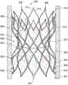
图36示出被配置成减小再捕获期间折叠事件的概率的用于假体心脏瓣膜的自膨式框架500的另一实施例。为了清晰起见,仅展示框架的前半部。框架500可包括流入端502和流出端504。框架500可由多个成角度的支柱构件506形成,所述多个成角度的支柱构件端对端布置以形成在框架周围周向延伸的多行或多个梯级的支柱构件。举例来说,框架500可包括形成框架的流入端502的第一或下部行I的成角度支柱构件506;第一行上方的第二行II的支柱构件;第二行上方的第三行III的支柱构件;第三行上方的第四行IV的支柱构件;以及第四行上方并形成框架的流出端504的第五行V的支柱构件。支柱506可在可划分相应行I-V的节点或接合部530处互连。在沿着框架的纵向轴线510的方向中跟踪,支柱506可组合以形成大体正弦形构件,其具有由接合部530形成的顶点以便提供网状物结构。Figure 36 illustrates another embodiment of a self-expanding
框架可包括大体柱形“上部”或流出端部分512、朝外弯曲或扩张的中间或腹部部分514,以及朝内弯曲的“下部”、腰部或流入端部分516,类似于图1的框架。中间部分514的大小和形状可设置为延伸到主动脉根部中的瓦尔萨尔瓦氏窦中以辅助锚定假体瓣膜,如上述实施例中那样。The frame may include a generally cylindrical "upper" or
当框架处于其膨胀状态时,中间部分514可具有直径D1,流入端部分516的腰部可具有最小直径D2,流入端502可具有直径D3,并且流出端部分512可具有直径D4,其中D2小于D1和D3,并且D4小于D2。与上述实施例一样,D1和D3可大于其中将植入假体瓣膜的自体环的直径,使得框架辅助将假体瓣膜保持在植入位点处。在某些实施例中,此配置还可减少或防止瓣周漏。When the frame is in its expanded state, the
支柱506可由例如镍钛诺或其它镍钛合金等形状记忆材料制成,其允许假体瓣膜被压缩到减小的直径以供在递送设备(例如上文描述)中递送,并且接着当从递送设备展开时致使假体瓣膜在患者身体内膨胀到其功能大小。在其它实施例中,框架还可包括例如镍-铬合金或不锈钢等延性材料,并且可被配置成与球囊可膨胀瓣膜一起使用。The
图37示出处于径向压缩状态的框架500的一行代表性支柱506。支柱506中的每个可包括流入端部分518、流出端部分520以及在流入端部分和流出端部分之间延伸的中间部分522。在某些实施例中,支柱506的尺寸可沿着其长度在支柱的流入端和流出端之间变化。在某些实施例中,一行支柱中的支柱的各个部分的尺寸可不同于相邻支柱行中的支柱的相应部分的尺寸。Figure 37 shows a representative row of
举例来说,支柱可包括通常在框架的弯曲的外表面的平面中测量的厚度或宽度尺寸,在本文中被称作“支柱宽度”W。再次参看图36,支柱506中的每个可具有当框架处于膨胀状态时通常取向于流入端502的方向上的表面524、在支柱的相对侧上并且当框架处于膨胀状态时通常取向于流出端504的方向上的相应表面526。每个支柱可进一步包括垂直于表面524且垂直于表面526的外表面528。如流入表面524和流出表面526之间测量的支柱506的厚度在本文中被称作支柱宽度W。换句话说,支柱宽度W是在垂直于支柱的纵向轴线的方向上测量的支柱506的外表面528的尺寸。支柱506中的每个可包括如上定义的支柱宽度。支柱构件的与外表面528相对的径向面朝内的表面的相应尺寸可以与外表面528的支柱宽度相同或不同,这取决于期望的特定特性。For example, a strut may include a thickness or width dimension, referred to herein as the "strut width" W, generally measured in the plane of the curved outer surface of the frame. Referring again to Figure 36, each of the
再次参看图36,支柱506还可具有在径向方向上从框架支柱的内表面向支柱的外表面528测量的壁厚度、径向厚度或支柱厚度T。在其中框架500由管件(例如,通过激光切割)形成的实施例中,框架的支柱可具有对应于从中切割框架的管件的壁厚度的厚度T。在其它实施例中,在激光切割之后管件和/或框架的壁厚度可变化(例如,通过机械加工、绞孔、蚀刻等),这可导致支柱的径向厚度的变化。Referring again to Figure 36, the
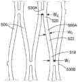
返回到图37,支柱506可限定流入端部分518处的第一支柱宽度W1、流出端部分520处的第二支柱宽度W2以及中间部分522处的第三支柱宽度W3。这些测量值在接合部530A(例如,支柱506A的流出接合部)和接合部530B(例如,支柱506A的流入接合部)之间延伸的代表性支柱构件506A上指示。图38更详细地示出接合部530B。参看图38,在某些实施例中,支柱行之间的接合部530可限定在相邻支柱构件之间延伸的具有半径r的弯曲表面。举例来说,代表性接合部530B可包括流入弯曲或凹表面532和流出弯曲或凹表面534。在某些实施例中,接合部530中的每个可包括与接合部的流入和流出方面类似的弯曲表面。Returning to FIG. 37 , struts 506 may define a first strut width W1 at
参看图38,在某些实施例中,可在接合部530B的流出的弯曲表面534的边缘处或边缘附近测量支柱宽度W1。在某些实施例中,可在接合部530B的流入的弯曲表面532的边缘处或边缘附近测量支柱宽度W2。在某些实施例中,可在相应接合部的弯曲表面的边缘和其中支柱宽度达到指定支柱宽度W3的位置之间的中点处测量支柱宽度W1和W2。在某些实施例中,支柱宽度W1可在沿着支柱的纵向轴线的方向上逐步地增加到支柱宽度W3。同样,在支柱的相对端处,支柱宽度W3可逐步地减小到支柱宽度W2。在其它实施例中,接合部中的一些或全部不必包括接合部的流入和流出方面的弯曲表面,而是可改为包括直线表面和/或凸表面。Referring to Figure 38, in some embodiments, the strut width Wi may be measured at or near the edge of the outflow curved
在某些实施例中,第三支柱宽度W3可大于支柱宽度W1和W2。在某些实施例中,支柱宽度W1和W2可以相同或不同,这取决于期望的特定特性。在某些实施例中,支柱宽度W1和W2可相等或大体上相等。如本文中所使用的,如果支柱宽度W1和W2的值相差10%或更小,则支柱宽度W1和W2大体上相等。在某些实施例中,减小接合部处的支柱宽度可有利地减小卷曲用于递送的瓣膜所需的径向力,如下文进一步描述的。In certain embodiments, the third strut width W3 may be greater than the strut widths W1 and W2 . In certain embodiments, strut widths W1 and W2 may be the same or different, depending on the particular characteristics desired. In certain embodiments, strut widths W1 and W2 may be equal or substantially equal. As used herein, strut widths W1 and W2 are substantially equal if the values of strut widths W1 and W2 differ by 10% or less. In certain embodiments, reducing the strut width at the commissure may advantageously reduce the radial force required to crimp the valve for delivery, as described further below.
在某些实施例中,支柱行I-V中的每一行中的支柱506可类似于代表性支柱构件506A而配置。在某些实施例中,支柱的各个部分的支柱宽度可在各行之间变化。举例来说,在某些实施例中,框架的流入端部分处的行I或行I和II的支柱可包括图37和图38中展示的不同的支柱宽度配置,而剩余行的支柱可包括不同配置(例如,沿着支柱的长度的均匀支柱宽度,或其它配置)。In certain embodiments, struts 506 in each of strut rows I-V may be configured similarly to
例如,图57示出了框架的另一实施例的接合部530,其中支柱506A和506B(例如,在接合部的流出侧上)包括不同的支柱宽度W1、W2和W3,并且支柱506C和506D(例如,在接合部的流入侧上)具有沿着其长度的恒定或大体上恒定的支柱宽度。在某些示例中,支柱506C和506D的支柱宽度可小于如图57中的支柱宽度W3(例如,W1或W2),或者等于或大体上等于W3,或者大于W3。举例来说,图58示出了另一配置,其中支柱506C和506D具有沿着大体上其整个长度的第三支柱宽度W3(或不同的支柱宽度),而接合部530的流出侧上的支柱506A和506B具有接合部处的减小的支柱宽度W1。图59示出了相反的配置,其中接合部530的流入侧上的支柱506C和506D具有接合部处的不同的支柱宽度,并且支柱506A和506B具有沿着其长度的恒定或大体上恒定的支柱宽度(例如,W3或不同的支柱宽度)。For example, FIG. 57 shows a joint 530 of another embodiment of a frame in which struts 506A and 506B (eg, on the outflow side of the joint) include different strut widths W1 , W2 , and W3 , and the
在例如接合部530等接合部处耦接在一起的任何两行支柱可具有本文中所描述的不同或恒定的支柱宽度配置中的任一个。举例来说,在某些实施例中,框架的支柱的至少一部分可包括在其相应接合部中的至少一个处,例如在其流入接合部(例如,图37中的接合部530B)处、在其流出接合部(例如,图37中的接合部530A)处或这两者处的减小的支柱宽度(例如,W1或W2)。在某些实施例中,框架的流入端处的第一行I支柱(图36)可包括其流入接合部、流出接合部或两者处的减小的支柱宽度。在某些实施例中,例如行I和II或行I-III或被配置成首先从递送护套展开的(一个或多个)行等等中的一个以上支柱行可包括在流入和/或流出接合部中的一或两者处的减小的支柱宽度。Any two rows of struts coupled together at a junction such as
在某些实施例中,支柱构件506的长度L可为4mm到6mm。在某些实施例中,支柱构件506的长度L可基于框架的指定的设计直径变化。举例来说,在某些示例中,如本文中所描述配置成具有26mm的指定的设计直径的框架可具有4.33mm的支柱长度L。具有29mm的指定直径的框架可具有4.79的支柱长度L,并且具有32mm的指定的设计直径的框架可具有5.3mm的长度L。In certain embodiments, the length L of the
返回到图38,接合部530B可限定如上所述的流入和流出的弯曲表面532和534。弯曲表面532和534可均包括半径r,但在其它实施例中,接合部的流入和流出侧上的半径可不同。接合部530B可限定沿着y轴在流入的弯曲表面532的顶点536和流出的弯曲表面534的顶点538之间延伸的厚度尺寸A。接合部530B还可限定在接合部的纵向取向的边缘540和542之间延伸的接合部宽度尺寸B。Returning to Figure 38, the joint 530B may define the inflow and outflow curved
本发明人已经发现,单独地和/或以各种组合的形式包含本文中所描述的一个或更多个参数的用于假体心脏瓣膜的自膨式框架可提供出人意料的优良性能,尤其是当需要在无折叠的情况下再捕获假体瓣膜时。本文中所描述的参数和框架实施例还可提供相对于使用于递送的瓣膜卷曲所需的径向力以及一旦在治疗位点处展开则由框架施加到周围解剖结构的“慢性”向外径向力的改进的性能。The present inventors have discovered that self-expanding frames for prosthetic heart valves that contain one or more of the parameters described herein, alone and/or in various combinations, can provide unexpectedly superior performance, especially When a prosthetic valve needs to be recaptured without folds. The parameters and frame embodiments described herein may also provide a "chronic" outer diameter relative to the radial force required to crimp the valve for delivery and applied by the frame to the surrounding anatomy once deployed at the treatment site Improved performance towards force.
举例来说,在某些实施例中,支柱宽度W1和/或W2与支柱宽度W3的比率可为0.7到0.95、0.75到0.95、0.8到0.95,或者小于或等于0.90。在特定实施例中,支柱宽度W1和W2可为0.29mm到0.32mm,并且支柱宽度W3可为0.33mm到0.37mm。减小接合部530附近的支柱宽度可减小使用于递送的瓣膜卷曲所需的径向力,同时减小框架在再捕获期间折叠的倾向。For example, in certain embodiments, theratioof strut widths Wi and/or W2 to strut width W3 may be 0.7 to 0.95, 0.75 to 0.95, 0.8 to 0.95, or lessthan or equal to 0.90. In certain embodiments, the strut widths W1 and W2 may be 0.29 mm to 0.32 mm, and the strut width W3 may be 0.33 mm to 0.37 mm. Reducing the strut width near the
在某些实施例中,支柱宽度W3与支柱厚度T的比率可为0.5到0.9、0.6到0.85、0.65到0.8,或者大于或等于0.65。在特定实施例中,支柱宽度W3可为0.33mm到0.37mm,并且支柱厚度T可为0.47mm到0.50mm。支柱宽度W3与支柱厚度T的比率在上文给定的范围内可减小框架在再捕获期间折叠的倾向。In certain embodiments, the ratio of strut width W3 to strut thickness T may be 0.5 to 0.9, 0.6 to 0.85, 0.65 to 0.8, or greater than or equal to 0.65. In certain embodiments, the strut width W3 may be 0.33 mm to 0.37 mm, and the strut thickness T may be 0.47 mm to 0.50 mm.The ratio of strut width W3 to strut thickness T within the ranges given above may reduce the tendency of the frame to collapse during recapture.
在某些实施例中,接合部530的接合部宽度B与支柱厚度T的比率可为1.4到3.2,例如1.5到2.5、1.5到2.1,或1.5到2.0。在某些实施例中,接合部宽度B与支柱厚度T的比率可大于或等于1.5,或者小于或等于2.1。在特定实施例中,接合部530的接合部宽度B可为0.7mm到1.5mm,例如0.8mm到1.0mm,或0.85到1.0mm。在特定实施例中,接合部宽度B可为0.91mm,并且支柱厚度T可为0.47mm到0.50mm。接合部的接合部宽度B与支柱厚度T的比率在上文给定的范围内可提供在用于在心脏中(例如在自体主动脉瓣膜处)进行植入的规范内的径向力和抗压碎值。举例来说,在某些实施例中,如本文中所描述而配置的框架在卷曲期间施加145N或更小(例如,121N或更小)的最大径向力,并且在膨胀到指定的设计直径之后施加30N或更大的慢性向外力。这些框架还显示5N到8N的抗压碎性。在某些实施例中,支柱厚度T可对抗压碎性具有相对大的效应,并且对径向力具有相对较小的明显效应,而接合部宽度B和/或流入和流出的支柱宽度W1和W2可对由压缩的框架所施加的径向力具有相对大的效应。In certain embodiments, the ratio of the junction width B to the strut thickness T of the
在某些实施例中,支柱宽度W3与接合部宽度B的比率可为0.25到0.7,例如0.3到0.6、0.3到0.5,或0.3到0.45。在某些实施例中,支柱宽度W3与接合部宽度B的比率可大于或等于0.3或者小于或等于0.45。在特定实施例中,支柱宽度W3可为0.33mm到0.37mm,并且接合部宽度B可为0.7mm到1.5mm,例如如上所述的0.91mm。In certain embodiments, the ratio of strut width W3 to junction width B may be 0.25 to 0.7, such as 0.3 to 0.6, 0.3 to 0.5, or 0.3 to 0.45. In certain embodiments, the ratioof strut width W3 to junction width B may be greater than or equal to 0.3 or less than or equal to 0.45. In certain embodiments, the strut width W3 may be 0.33 mm to 0.37 mm, and the junction width B may be 0.7 mm to 1.5 mm, such as 0.91 mm as described above.
在某些实施例中,支柱宽度W1和/或W2与接合部宽度B的比率可为0.2到0.5,例如0.25到0.45或0.3到0.4。在某些实施例中,支柱宽度W1和/或W2与接合部宽度B的比率可大于或等于0.3或者小于或等于0.4。在特定实施例中,支柱宽度W1和/或W2可为0.29mm到0.32mm,并且接合部宽度B可为0.7mm到1.5mm,例如如上所述的0.91mm。In certain embodiments, the ratio of strut widths W1 and/or W2 to junction width B may be 0.2 to 0.5, such as 0.25 to 0.45 or 0.3 to 0.4. In certain embodiments, theratio of strut widths W1 and/or W2 to junction width B may be greaterthan or equal to 0.3 or less than or equal to 0.4. In certain embodiments, the strut widths W1 and/or W2 may be 0.29 mm to 0.32 mm, and the junction width B may be 0.7 mm to 1.5 mm, such as 0.91 mm as described above.
在某些实施例中,支柱的流出端520的支柱宽度W2与接合部的弯曲的流入表面532的半径r的比率可为4.0到7.5,例如4.1到7.1。支柱的流入端518的支柱宽度W1与弯曲的流出表面534的半径r的比率可具有类似值。在特定实施例中,接合部530的弯曲表面532和/或534的半径r可为0.04mm到0.08mm,例如从0.044mm到0.07mm。这些范围内的半径可改进所得表面的可制造性和精确度,尤其是当使用激光切割技术并且激光束的直径可为0.04mm时。较大接合部半径可促进激光切割期间穿过框架的金属的较均匀的热分布,并且还可减少由于反复卷曲而在接合部处形成微裂缝。In certain embodiments, the ratio of the strut width W2 of the
在某些实施例中,在从管件切割框架之后,框架可被电解抛光、电化学抛光和/或在蚀刻剂中蚀刻。这些工艺可以更改所切割框架的支柱宽度、厚度和/或接合部半径参数。因此,在某些实施例中,框架的质量可用于推断支柱宽度、支柱厚度和/或接合部半径参数是否在指定范围内。举例来说,在如本文中所描述而配置的框架500的某些实施例中,框架的质量可在800mg到1,100mg范围内变化,例如在875mg到1,000mg或950mg到990mg之间变化。在特定实施例中,如本文中所描述而配置的框架500的质量可为975mg。In certain embodiments, after cutting the frame from the tubing, the frame may be electropolished, electrochemically polished, and/or etched in an etchant. These processes can alter the strut width, thickness and/or joint radius parameters of the frame being cut. Thus, in some embodiments, the mass of the frame can be used to infer whether the strut width, strut thickness, and/or joint radius parameters are within specified ranges. For example, in certain embodiments of
在某些实施例中,张开的流入端部分516可相对于纵向轴线510限定角度θ。在某些实施例中,配置流入端部分使得角度θ在规定范围内可减小框架在再捕获期间折叠的倾向。将角度θ保持在规定范围内还可减小流入端部分516接触希氏束(the bundle of His)并干扰植入后心脏中的电信令的概率。在某些示例中,例如25°或更小或21°或更小的小于30°的角度θ可提供流入端部分516的充分的张开以将假体瓣膜锚定在自体瓣膜环中,同时降低在再捕获期间折叠和/或接触希氏束的风险。在特定实施例中,21°的角度θ结合定位框架使得5mm的流入端部分516延伸到左心室中可降低接触希氏束的风险。In certain embodiments, flared
可减小再捕获期间折叠的概率的另一参数是递送筒的内径与当从递送筒部分地展开时框架的张开的流入端的直径的比率。在某些实施例中,框架可被配置成膨胀到指定的设计直径(也称为指定直径、设计直径或展开直径)。假体瓣膜的特定的指定的设计直径可对应于例如假体瓣膜将植入到的个体的解剖结构的大小和形状。对于如本文中所描述而配置的自膨式框架,指定的设计直径可在流入端部分516的最窄点处在框架的内表面之间测量。在其它实施例中,指定的设计直径可在框架膨胀到其功能大小时沿着其长度的任何地方在框架的最小内径的位置处测量。图36中示出了框架500的指定的设计直径DSPEC。举例来说,在某些实施例中,如本文中配置的假体心脏瓣膜可具备23mm、26mm、28mm、29mm和32mm或更大的指定的设计直径。Another parameter that can reduce the probability of folding during recapture is the ratio of the inner diameter of the delivery barrel to the diameter of the flared inflow end of the frame when partially unfolded from the delivery barrel. In certain embodiments, the frame may be configured to expand to a specified design diameter (also referred to as a specified diameter, design diameter, or deployed diameter). The particular designated design diameter of the prosthetic valve may correspond, for example, to the size and shape of the anatomy of the individual into which the prosthetic valve will be implanted. For a self-expanding frame configured as described herein, the specified design diameter may be measured between the inner surfaces of the frame at the narrowest point of the
通常,假体心脏瓣膜的指定的设计直径被选择为稍微大于患者的自体环(例如,可选择32mm假体瓣膜来治疗具有30mm自体环直径的患者)。在某些实施例中,具有至少29mm或更大的指定的设计直径的假体心脏瓣膜可较容易在部分展开之后的再捕获期间折叠。在某些实施例中,部分膨胀的假体瓣膜的流入端的直径与递送筒的内径的比率可影响再捕获期间框架折叠或屈曲的倾向。例如,图39示出了框架500从递送筒544部分地展开。出于说明的目的,框架500的在递送筒544内部的部分以虚线示意性地示出。递送筒544可具有内径D5,并且框架的张开的流入端502可具有直径D6。在某些实施例中,递送筒544的内径D5可对于具有32mm的指定的设计直径的假体瓣膜为6.35mm,对于具有29mm的指定的设计直径的假体瓣膜为6.1mm,并且对于具有26mm的指定的设计直径的框架为5.85mm。Typically, the designated design diameter of a prosthetic heart valve is chosen to be slightly larger than the patient's native annulus (eg, a 32 mm prosthetic valve may be selected to treat a patient with a 30 mm native annulus diameter). In certain embodiments, a prosthetic heart valve having a designated design diameter of at least 29 mm or greater can be more easily folded during recapture after partial deployment. In certain embodiments, the ratio of the diameter of the inflow end of the partially expanded prosthetic valve to the inner diameter of the delivery barrel can affect the propensity of the frame to fold or flex during recapture. For example, FIG. 39 shows
图40示出了当框架的总长度Y的60%已展开时以及当框架的总长度的80%已展开时框架500的位于递送筒外部的部分。如本文中所使用的,框架500的总长度Y可以是当框架膨胀到其指定的设计直径时在流入端502和流出端504之间测量的框架的长度。因此,纬度线546对应于框架的总长度Y的60%,并且纬度线548对应于框架的总长度Y的80%。在所说明的实施例中,纬度线546刚好落在接合部530'上方,使支柱行III与支柱行IV分离(图36)。换句话说,当框架的总长度Y的60%已从递送筒展开(图40中544处示意性示出的)时,接合部530'正好从递送筒的远端射出。在所说明的实施例中,纬度线548刚好落在接合部530”上方,使支柱行IV与支柱行V分离(图36)。因此,如本文中所使用的,展开框架的总长度的80%指满足以下条件的点:当框架处于其指定的设计直径时在流入端502和流出端504之间的距离的80%处的框架上的位置548已露出或在递送筒外部(例如,远侧)。在所说明的配置中,当接合部530”从递送筒544射出时,框架的总长度Y的80%已展开。Figure 40 shows the portion of the
下面的表1提供了类似于图36的框架500配置的29mm框架和32mm框架的示例性尺寸。这些框架实施例被测试并且在部分地展开且框架的总长度的80%露出之后成功地再捕获到递送筒中。Table 1 below provides exemplary dimensions for a 29mm frame and a 32mm frame configured similar to the
表1:29mm和32mm自膨式框架的测量值Table 1: Measurements for 29mm and 32mm Self-Expanding Frames


在某些实施例中,当框架500的总长度Y(图40)的80%已从递送筒544展开时,框架的流入端502的直径D6与递送筒544的内径D5的比率可大于4.5,例如为4.5到8.0,5.0到7.0,5.0到6.0,5.2到6.2或5.5到6.0。在某些实施例中,对于具有29mm或更大的指定的设计直径的框架,当框架的总长度Y的80%已从递送筒展开时,框架的流入端502的直径D6与递送筒544的内径D5的比率可小于或等于6.0。在特定实施例中,当框架的总长度的80%从递送筒展开时流入端502的直径D6与递送筒544的内径D5的比率可为5.7到6.0。在某些实施例中,D6与D5的比率在上述范围内可显著减小再捕获期间折叠的概率,尤其是对于其中在框架的总长度的80%或更大从递送筒展开的情况下尝试再捕获的较大的设计直径瓣膜。In certain embodiments, when 80% of the overall length Y ( FIG.40 ) of the frame500 has been deployed from the
在某些实施例中,本文中所描述的递送筒和/或设备中的任一个可被配置成递送其它类型的自膨式植入物,例如下文描述的假体心脏瓣膜对接台、支架等中的任一个。In certain embodiments, any of the delivery cartridges and/or devices described herein may be configured to deliver other types of self-expanding implants, such as prosthetic heart valve docking stations, stents, etc. described below any of the.
除了减小折叠概率外,本文中所描述的框架实施例还满足包括以下参数的指定值:针对轴向力的阻力(也被称为压碎力或抗压碎性)、瓣膜的初始卷曲期间所需的径向力以及植入后由框架抵着周围组织施加的径向力(也被称为“慢性向外力”)。图41示出了作为具有32mm的指定设计直径且如上文所述配置的框架的框架直径的函数的力的曲线。卷曲之前框架的自然不受限的直径为约37mm。随着框架卷曲,直径和力遵循上部曲线602到最小直径6-7mm。在此直径处,由框架抵着递送筒施加的径向力(例如,保持框架径向受限所需的力)为约135N。随着框架膨胀,力/直径关系遵循下部曲线604。通常,对于目标环,自膨式框架的大小超出了1-2mm。因此,在30mm的直径处,32mm框架施加约30N的慢性向外径向力。现有32mm的自膨式框架施加约145N的最大径向力和30N的慢性向外径向力。In addition to reducing the probability of collapse, the frame embodiments described herein satisfy specified values including: resistance to axial force (also known as crush force or crush resistance), during initial crimping of the valve The required radial force and the radial force exerted by the frame against the surrounding tissue after implantation (also referred to as "chronic outward force"). Figure 41 shows a plot of force as a function of frame diameter for a frame having a specified design diameter of 32 mm and configured as described above. The natural unrestricted diameter of the frame before crimping is about 37 mm. As the frame crimps, the diameter and force follows the
本文中所描述的自膨式框架的不同实施例可提供优于现有自膨式框架的一个或更多个显著优点。举例来说,本文中所描述的框架的某些实施例可允许反复地部分展开和再捕获具有相对大的指定的设计直径的框架,而无折叠或内陷。举例来说,如本文中所述配置的具有32mm的指定的设计直径的自膨式框架在展开框架的总长度的80%、框架的总长度的90%、框架的总长度的95%以及框架的总长度的98%之后被成功地再捕获,均无折叠。反复地部分展开和再捕获大直径自膨式瓣膜的能力在尝试将假体瓣膜放置在相对大的解剖结构中时可提供显著优点,并且可降低在手术中途可能需要新的假体瓣膜的风险。本文中所描述的框架还满足径向卷曲力(例如,145N或更小)和在治疗位点处膨胀时的慢性向外力(例如,28N到30N或更大)的规范。The different embodiments of self-expanding frames described herein may provide one or more significant advantages over existing self-expanding frames. For example, certain embodiments of the frames described herein may allow for repeated partial deployment and recapture of a frame having a relatively large specified design diameter without folding or indentation. For example, a self-expanding frame configured as described herein with a specified design diameter of 32 mm is deployed at 80% of the overall length of the frame, 90% of the overall length of the frame, 95% of the overall length of the frame, and After 98% of the total length was successfully recaptured, none were folded. The ability to repeatedly partially deploy and recapture large-diameter self-expanding valves may provide significant advantages when attempting to place prosthetic valves in relatively large anatomical structures and may reduce the risk that a new prosthetic valve may be required mid-operatively . The frameworks described herein also meet the specifications for radial crimp force (eg, 145N or less) and chronic outward force (eg, 28N to 30N or more) when expanded at the treatment site.
图42-44示出了具有32mm的指定的设计直径的框架500的实施例成功地再捕获到具有6.35mm的内径的递送护套544中。在图42中,框架的总长度的80%从递送筒544展开。在图43中,再捕获在进行中,并且图44示出了框架完全再捕获于递送护套544内而无折叠。42-44 illustrate the successful recapture of an embodiment of the
工作示例1Working Example 1
在代表性工作示例中,使用图45中示出的径向膨胀力计量设备700进行框架500的径向力和慢性向外力的测试和测量。设备700包含主体702和虹膜组件704,所述虹膜组件包括多个楔形构件或心轴706。构件706限定被配置成接收框架500的中心开口或管腔708。构件706可被致动以沿着框架的长度可控地且均匀地减小管腔708的直径以便使框架径向塌缩。In a representative working example, the radial force and chronic outward force of
通过(例如)检查设备700为水平的并且所述设备处于规定温度来校准测试器设备700。在本示例中,在37℃下进行测试。为了校准设备700的温度读数,将例如热电偶和/或经校准数字温度计等经校准温度传感器插入到设备的环境舱头部中,例如插入到管腔708中,达到50.8mm到76.2mm的深度。在指定时间周期(例如,5分钟)之后,输入温度补偿值,使得设备的温度读数与温度传感器匹配。The
为了校准虹膜组件704的直径,将6mm直径计量销插入到管腔708中至少40mm,并且运行校准例程。接下来,将40mm直径计量销插入到虹膜组件中至少40mm,并且运行校准例程。为了校准设备700的(一个或多个)称重传感器(load cell),当螺杆712为水平(例如,处于10mm直径)时从设备700上的指定螺杆712附接或悬挂校准轭710。接着将不同质量的重块714附接到轭710以校准称重传感器。To calibrate the diameter of
接着检查虹膜组件704的各个元件的摩擦。在本示例中,测量到的摩擦在±1.5N径向力内。Next, the various elements of the
在测试期间,为32mm框架选择预设例程,其在37mm的第一直径处开始,并且以0.5mm/s的速率径向收缩到6.35mm的第二直径(对应于递送筒的内径)。将框架插入到管腔708中,并且允许框架适应环境两分钟,然后起动测试。接着测量由压缩的框架施加的径向力,并且其结果在径向力与图41中示出的直径的曲线图中示出。During testing, a preset routine was selected for the 32mm frame, which started at a first diameter of 37mm and contracted radially to a second diameter (corresponding to the inner diameter of the delivery barrel) of 6.35mm at a rate of 0.5mm/s. The frame was inserted into
第三代表性示例Third representative example
上文描述的不同支柱宽度、接合部宽度、接合部半径等还可实施于用于其它类型的假体植入物的框架上,例如被配置成接收假体心脏瓣膜的对接台或系统。此对接台的一个代表性示例在图47A-51中示出。The different strut widths, joint widths, joint radii, etc. described above may also be implemented on frames for other types of prosthetic implants, such as docking stations or systems configured to receive a prosthetic heart valve. A representative example of such a docking station is shown in Figures 47A-51.
图47A和图47B示出了对接台802的框架800或主体的示例性实施例。框架800或主体可采取广泛多种不同形式,并且图47A和图47B仅示出许多可能配置中的一个。在由图47A和图47B示出的示例中,对接台802具有相对较宽近侧流入端804和远侧流出端806,以及形成端部804、806之间的支座810的相对较窄部分808。在由图47A和图47B示出的示例中,对接台802的框架800优选地是由形成小室814的多个金属支柱812构成的宽支架。在图47A和图47B的示例中,框架800具有带有窄部分808的大体沙漏形状,其当被不可渗透材料覆盖时在近端804和远端806之间形成瓣膜支座810。如下文所描述的,假体瓣膜在窄部分808中膨胀,从而形成瓣膜支座810。47A and 47B illustrate an exemplary embodiment of the
图47A和图47B示出了处于其不受限膨胀状态中的框架800。在此示例性实施例中,保持部分816包括近端804和远端806处的金属支柱812的端部818。密封部分820在保持部分816和腰部808之间。在不受限的状态中,保持部分816大体径向朝外延伸并且从密封部分820径向朝外。框架800可通过导管径向压缩以供递送及膨胀。对接台可由弹性或顺应性材料制成以适应解剖结构中的较大变化。举例来说,对接台可由高度柔性金属、金属合金、聚合物或开孔泡沫制成。高度弹性金属的示例为镍钛诺,但可使用其它金属和高度弹性或顺应性非金属材料。对接台802可为自膨式、可手动膨胀(例如,可经由球囊膨胀)或可机械膨胀的。自膨式对接台802可由例如镍钛诺等形状记忆材料制成。47A and 47B illustrate the
图48示出了假体瓣膜822植入在框架800中。当对接在对接台内时,瓣膜822可任选地在瓣膜支座的任一侧周围稍微膨胀。这方面(有时被称作“狗骨(dogbone)”)(例如,由于其在瓣膜支座或条带周围形成的形状的缘故)还可有助于将瓣膜保持在适当位置。在某些实施例中,假体瓣膜822可为可购自Edwards Lifesciences(爱德华兹生命科学)公司的

图49和图50示出了图47A的对接台802植入在循环系统中,例如肺动脉中。密封部分820提供对接台802和循环系统的内表面824之间的密封。在图49和图50的示例中,通过在框架800或其部分上方提供不可渗透材料826(参看图50)来形成密封部分820。确切地说,密封部分820可包括框架800的下部圆形的径向朝外的延伸部分828。在示例性实施例中,不可渗透材料826至少从框架800的部分828延伸到瓣膜支座810。这使对接台不可从密封部分820渗透到瓣膜密封件810。如此,流入方向804中朝向流出方向806流动的所有血液均被导向到瓣膜支座810(和瓣膜822,一旦其安装或展开于瓣膜支座中)。Figures 49 and 50 show the
在对接台802的优选实施例中,流入部分具有血液不可渗透的壁,但流出部分壁是相对开放的。在一个方法中,流入端部分分804、中间节段808和流出端部分分806的一部分覆盖有血液不可渗透的织物826,其可缝合到支架上或否则通过本领域已知的方法附接。支架的流入部分的不渗透性有助于血液汇集到对接台802中,并且最终流动穿过待膨胀并固定于对接台802内的瓣膜。In a preferred embodiment of
从另一视角来看,对接台的该实施例被设计成在近侧流入节段828处密封以形成血流的管道。然而,远侧流出节段通常保持开放,借此允许对接台802放置在肺动脉中较高处,而不限制血流。举例来说,可渗透部分830可延伸到肺动脉的分支中,并且不妨碍或不显著妨碍血液流过所述分支。在一个实施例中,例如PET布等血液不可渗透的布或其它材料覆盖近侧流入节段,但覆盖件不会覆盖远侧流出节段806的任何或至少一部分。作为一个非限制性示例,当对接台802放置于肺动脉(其为较大血管)中时,流经动脉的较大体积的血液通过布覆盖件826汇集到瓣膜822中。布826是流体不可渗透的,使得血液无法通过。再次,可使用多种其它生物相容性覆盖材料,例如用血液不可渗透的涂层处理的泡沫或织物、聚酯或经处理的生物材料(例如心包)。From another perspective, this embodiment of the docking station is designed to seal at the
在图50示出的示例中,向对接台框架800的较大部分提供不可渗透材料826,从而形成相对大的不可渗透部分832。在由图50示出的示例中,不可渗透部分830从流入端804延伸并且在流出端之前一行小室814处停止。如此,最远侧行的小室814形成可渗透部分830。然而,较多行的小室814可以不被不可渗透材料覆盖以形成较大的可渗透部分。可渗透部分830允许血液流入和流出区域834,如由箭头836所指示的。相对于流入端804,应注意,因为小室814为大体钻石形状,所以血液能够在对接台802和表面824之间流动,直至到达密封部分820。也就是说,在一个示例性实施例中,血液可流入和流出区域838。In the example shown in FIG. 50 , the
瓣膜支座810可提供用于在对接台802中植入或展开瓣膜822的支撑表面。保持部分816可将对接台802保持在循环系统中的植入位置或展开位点处。所示出的保持部分具有朝外弯曲的张开部,其帮助将对接台802固定在动脉内。如本文所使用的,“朝外”意味着背离对接台的中心纵向轴线延伸。如图49中可看出的,当对接台802由内表面824压缩时,保持部分816以角度α啮合表面824(垂直于与保持部分816的表面的中点相切的表面),所述角度可在30度和60度之间,例如约45度,而非如未经压缩状态(参看图47B)中大体上径向朝外延伸(例如,α为0到20度或约10度)。如由箭头840所指示的保持部分816的此向内弯曲用以将对接台802保持在循环系统中。保持部分816在较宽流入端部分804和流出端部分806处,并且抵着内表面824按压。张开的保持部分816啮合到循环系统中的周围解剖结构中,例如肺部空间中。在一个示例性实施例中,张开部充当止挡件,其将装置锁定在适当位置。当轴向力施加到对接台802时,张开的保持部分816通过所述力推动到周围组织中以抵抗支架的迁移,如下文更详细地描述的。在特定实施例中,对接台通常具有沙漏形状,其较宽远端和近端部分具有张开的保持部分和端部之间的窄带状腰部,瓣膜膨胀到其中。The
图51示出了对接台802展开在循环系统中,并且瓣膜822展开在对接台802中。在对接台802展开之后,瓣膜822处于被压缩形式并且被引入到对接台802的瓣膜支座810中。瓣膜822在对接台中膨胀,使得瓣膜822啮合瓣膜支座810。在由图51示出的示例中,对接台802比瓣膜更长。然而,在一个实施例中,对接台802可具有与瓣膜822的长度相同或短于瓣膜822的长度的长度。51 shows the
假体瓣膜822可经由包含球囊或机械膨胀的构件或通过自行膨胀而在对接台的位点处膨胀。当瓣膜822膨胀时,其嵌套在对接台802的瓣膜支座中。在一个实施例中,带状腰部稍微具有弹性,并且抵着假体瓣膜822施加弹力,以有助于将假体瓣膜保持在适当位置。The
如上所述,对接台框架800的支柱中的任一个可包括上文描述的不同支柱宽度、接合部宽度、接合部半径等。举例来说,框架800的各行支柱中的任一行中的支柱可根据本文中所描述的比率中的任一个包括接合部附近的变窄或渐缩支柱宽度,以及位于接合部之间的部分处的较宽中间支柱宽度。根据本文中所描述的比率中的任一个,接合部的宽度还可大于中间支柱宽度。对接台800的流入端的直径与对接台从中展开的递送筒的内径的比率还可小于或等于6.0,如上文所述。这些特征中的任一个或全部单独和/或以组合方式均可减小对接台框架800在展开和再捕获期间折叠的倾向。关于对接台800的额外细节可见于以引用的方式并入本文中的第2017/0231756号美国公开案。As noted above, any of the struts of
第四代表性实施例Fourth Representative Embodiment
图52-53B示出了被配置成接收假体心脏瓣膜的对接系统900的另一实施例,并且其可以各种组合包括本文中所描述的不同支柱宽度、接合部宽度、接合部半径等中的任一个。图52示出了包括布置成晶格图案的多个支柱构件903的对接系统900的框架902的示例性实施例。在某些实施例中,支柱903的长度和/或厚度可变化,如以引用的方式并入本文中的第2019/0000615号美国公开案中所述。框架902可采取广泛多种不同形式,并且图52仅示出许多可能配置中的一个。在某些实施例中,框架902可包括例如镍钛诺等弹性或超弹性材料或金属。52-53B illustrate another embodiment of a
框架902可包括保持部分904,所述保持部分904包括具有圆环形端面908的环形外部部分或壁906。环形外部部分906的定形(例如,形状记忆材料的经编程的形状)可使壁906径向朝外偏置成接触/抵着血管(例如,主动脉)的内表面,以将对接台900和接收在其中的假体瓣膜保持在植入位置处。框架902可进一步包括支腿或构件910,其从框架的周界延伸到管腔中以用于支撑瓣膜支座912,所述瓣膜支座可被配置成接收假体心脏瓣膜,例如本文中所述的假体心脏瓣膜中的任一个。The
参看图53A和图53B,在某些实施例中,框架902可包括密封材料或覆盖件914,其安置于框架的端部908上以实现瓣膜支座912中接收的假体心脏瓣膜和周围解剖结构之间的密封。覆盖件914可被配置成自身向后部分卷起的筒。覆盖件914可包括一片或多片聚对苯二甲酸伸乙酯(PET)、聚四氟乙烯(PTFE)、膨胀PTFE(ePTFE)或任何其它聚合物或生物相容性材料。在某些实施例中,覆盖件914可包括包含上述材料中的任一个的编织或针织物。覆盖件914的另外细节可见于以引用的方式并入上文的第2019/0000615号美国公开案。53A and 53B, in certain embodiments, the
图60示出了被配置成接收假体心脏瓣膜的对接系统的框架1200的另一实施例,并且其也可包括本文中所述的不同支柱宽度、接合部宽度、接合部半径等中的任一个。框架1200可包括流入端部分1204和流出端部分1206。框架1200可包括在框架1200周围彼此周向间隔开的多个纵向支柱构件1208。框架可进一步包括以Z形图案交替地布置的多行支柱1210。所述多行支柱1210可沿着框架的纵向轴线1212彼此轴向间隔开。举例来说,在所说明的实施例中,框架1200可包括十一行I-XI支柱1210,其中第一行I位于流入端部分1204处并且第十一行XI位于流出端部分1206处。支柱1210被布置成使得支柱的第一端部在接合部1220处耦接到纵向支柱构件1208,并且支柱的第二端部耦接到邻近支柱1210的第二端部以形成“自由”顶点1218。流出端部分1206可包括耦接到第十一行XI支柱的接合部1220的多个支柱1222。支柱1222可在下游方向中延伸,并且可径向朝内朝向纵向轴线1212成角度以限定大体在1228处指示的瓣膜接收部分或瓣膜支座,所述瓣膜接收部分或瓣膜支座可与框架1200同轴并且被配置成接收假体瓣膜。对接台框架1200的另外细节可见于以引用的方式并入本文中的第63/073,643号美国临时申请。Figure 60 illustrates another embodiment of a
对接台框架900和/或1200的支柱中的任一个可包括上文描述的不同支柱宽度、接合部宽度、接合部半径等。举例来说,框架900和/或1200的各行支柱中的任一行中的支柱可根据本文中所描述的比率中的任一个包括接合部附近的变窄或渐缩支柱宽度,以及位于接合部之间的部分处的较宽中间支柱宽度。根据本文中所描述的比率中的任一个,接合部的宽度还可大于中间支柱宽度。对接台框架900和/或1200的流入端的直径与对接台从中展开的递送筒的内径的比率还可小于或等于6.0,如上文所述。支柱和接合部还可被配置成使得各种支柱宽度与接合部的弯曲表面的半径的比率落在本文中所述的范围中的任一个内。这些特征中的任一个或全部单独地和/或以组合方式可减小对接台框架900和1200在展开和再捕获期间折叠的倾向。Any of the struts of
第五代表性实施例Fifth Representative Embodiment
图54示出包括在接合部1004处耦接在一起的多个成角度支柱1002的假体心脏瓣膜的框架1000的另一实施例。框架1000可被配置成包括本文中所描述的自膨式材料中的任一个的自膨式框架,并且可在塌缩递送配置和膨胀功能配置之间移动。框架可具有流入端1006和流出端1008。框架1000的直径可沿着其纵向轴线1010变化,如所展示的。FIG. 54 shows another embodiment of a
图55示出了框架1000的选择的部分。支柱1002可包括在相应接合部1004附近的第一或流入端部分1012和第二或流出端部分1014。支柱可进一步包括位于流入端部分1012和流出端部分1014之间的第三或中间部分1016。流入端部分1012可具有支柱宽度W1,并且流出端部分1014可具有支柱宽度W2。尽管支柱被显示为从接合部朝向支柱的中部变窄,但在某些实施例中,中间部分1016可具有大于如上文所述的支柱宽度W1和W2的支柱宽度W3。支柱宽度W1、W2和W3可具有本文中所述的值和比率中的任一个。FIG. 55 shows selected portions of the
接合部1004还可包括接合部宽度B。接合部宽度B可大于如上文所述的中间支柱宽度W3。中间支柱宽度W3与接合部宽度B的比率可以是本文中所描述的比率中的任一个。支柱1002还可具有根据本文中所述的尺寸和比率中的任一个配置的支柱厚度。在某些实施例中,框架1000可被配置成使得当框架的总长度的80%从递送筒展开时,框架的张开的流入端(或流出端)的直径与递送筒的内径的比率为6.0或更小。支柱和接合部还可被配置成使得各种支柱宽度与接合部的弯曲表面的半径的比率落在本文中所描述的范围中的任一个内。在某些实施例中,这些特征单独地和/或以各种组合可减小假体瓣膜的装载、展开和/或再捕获期间框架1000折叠的倾向。The
图56示出了包括多个成角度支柱构件1102、流入端1104和流出端1106的用于自膨式假体心脏瓣膜的框架1100的另一实施例。框架支柱1102可根据本文所描述的任一实施例配置以减小假体瓣膜的装载、展开和/或再捕获期间框架1100折叠的倾向。FIG. 56 shows another embodiment of a
第六代表性实施例Sixth Representative Embodiment
本文中所描述的框架支柱配置、接合部宽度配置等中的任一个还可与包含多个框架或多层框架(例如内部框架和外部框架)的假体装置组合实施。此外,对于其中流出端首先从递送护套展开的假体植入物,本文中所描述的不同支柱宽度概念可至少在框架的流出端处实施于支柱上。此类植入物可包含被配置成用于植入(例如,经中隔)在自体二尖瓣中的假体心脏瓣膜。举例来说,图61-64示出了被配置成假体心脏瓣膜1300的自膨式假体植入物的另一实施例,所述假体心脏瓣膜1300被配置成用于植入在自体二尖瓣中。参看图61,假体心脏瓣膜1300可包括内部框架1302和外部框架1304。假体心脏瓣膜1300还可具有流入端1303和流出端1305。外部框架1304可具有上部区域1306、中间区域1308和下部区域1310。在一些情况下(例如其中假体1300定位在自体二尖瓣内的情况),上部区域1306可通常环形向上定位,中间区域1308可通常环形向内定位,并且下部区域1310可环形向下定位。图63中独立地描绘了外部框架1302。Any of the frame strut configurations, joint width configurations, etc. described herein may also be implemented in combination with prosthetic devices comprising multiple frames or multiple layers of frames (eg, inner and outer frames). Furthermore, for prosthetic implants in which the outflow end is first deployed from the delivery sheath, the different strut width concepts described herein may be implemented on the struts at least at the outflow end of the frame. Such implants may comprise a prosthetic heart valve configured for implantation (eg, transseptal) in a native mitral valve. For example, FIGS. 61-64 illustrate another embodiment of a self-expanding prosthetic implant configured as a
图62中示出了内部框架1302的代表性实施例。内部框架1302可包含上部区域1312、中间区域1314和下部区域1316。如所展示的,中间区域1314可具有比上部区域1312和/或下部区域1316更小的直径。这可形成沙漏形状,其中中间区域1314的直径比上部区域1312和下部区域1316更细。在一些实施例中,上部区域1312和下部区域1316可具有大致相同的直径。在某些实施例中,内部框架1302可包括内部框架锚定特征,其包含多个独立的锚构件1318,所述锚构件在径向朝外方向中从下部区域1316曲线延伸并且包括被配置成在植入于自体二尖瓣后接触/啮合腔内组织的尖端。内部框架1302还可包括被配置成将假体瓣膜耦接到递送系统的多个锁定凸台1320。A representative embodiment of an
参看图63,外部框架1304可包含多个支柱,其中至少一些支柱形成小室1322。小室1322可具有不规则八角形形状,例如“泪珠”形状,并且可经由支柱的组合形成。如所说明的实施例中所示,小室1322的上部部分可由一组可周向扩展的支柱1326形成,所述可周向扩展的支柱具有Z形或波状形状,从而形成重复的“V”形。可周向扩展的支柱1326可背离假体100的纵向轴线径向朝外倾斜或弯曲,使得支柱1326的上部部分被定位成比支柱1326的下部部分更接近假体1300的纵向轴线。小室1322的底部部分可由一组支柱1328形成,所述支柱1328从“V”形中的每个的中心或大体中心位置向下延伸。支柱1328可连同平行于和/或延伸穿过假体100的纵向轴线的平面一起延伸。小室1322的几何结构可允许小室1322随着外部框架1304膨胀而提前缩短,这可用于将假体固定到自体瓣膜中或周围的腔内组织。Referring to FIG. 63 , the
假体心脏瓣膜1300的内部和/或外部框架的支柱中的任一个或全部可包括本文中所描述的不同支柱宽度概念中的任一个。例如,图64示出了外部框架1304处于放平配置。在某些实施例中,外部框架1304的支柱1328可包括流入端部分1330和流出端部分1332。流入端部分1330可限定弓形/圆形/环状顶点或接合部1334。在接合部1334处或附近,支柱1328可包括减小的支柱宽度。举例来说,支柱的流入端部分1330可包括支柱宽度S1,并且流出端部分以及流入端部分和流出端部分之间的中间部分可包括大于支柱宽度S1的支柱宽度S2。在某些实施例中,这可减小假体瓣膜1300的再捕获期间折叠的概率。在其它实施例中,支柱1328的流入端部分和流出端部分两者可包括相比于支柱的中间部分减小的支柱宽度。接合部1334还可包括本文中所述的半径和/或宽度尺寸中的任一个,和/或支柱1328的(一个或多个)宽度可限定本文中所述的与接合部1334的宽度和/或半径的比率中的任一个。在某些实施例中,图64中展示的减小的支柱宽度可实施于支柱1328的流出端部分1332上。减小的支柱宽度还可实施于内部框架的支柱中的任一个上。关于假体心脏瓣膜1300的另外细节可见于以引用的方式并入本文中的第2019/0262129号美国公开案。Any or all of the struts of the inner and/or outer frame of
条款解释Terms Explanation
出于本说明的目的,本文描述了本公开的实施例的某些方面、优点和新颖特征。所公开的方法、设备和系统不应以任何方式解释为限制性的。相反,本公开涉及各种公开的实施例(单独和与彼此的各种组合和子组合)的所有新颖和非显而易见的特征和方面。方法、设备和系统不限于任何特定方面或特征或其组合,所公开的实施例也不要求应存在任何一个或更多个特定优点或应解决问题。For the purposes of this description, certain aspects, advantages, and novel features of embodiments of the present disclosure have been described herein. The disclosed methods, apparatus and systems should not be construed as limiting in any way. Rather, the present disclosure relates to all novel and non-obvious features and aspects of the various disclosed embodiments, alone and in various combinations and subcombinations with each other. The methods, apparatus, and systems are not limited to any particular aspect or feature, or combination thereof, nor do the disclosed embodiments require that any one or more particular advantages be present or problems be solved.
尽管为了方便呈现,以特定的循序次序描述了所公开的实施例中的一些实施例的操作,但是应当理解的是,这种描述方式涵盖了重新布置,除非以下阐述的具体语言要求特定排序。举例来说,在一些情况下,可重新布置或同时执行循序描述的操作。此外,为简单起见,附图可能未展示其中所公开的方法可结合其它方法一起使用的各种方式。另外,本说明书有时使用比如“提供”和“实现”等术语来描述所公开的方法。这些术语是所执行的实际操作的高水平抽象。对应于这些术语的实际操作可取决于特定实施方案而变化且易于由本领域普通技术人员辨别。Although the operations of some of the disclosed embodiments have been described in a particular sequential order for ease of presentation, it is to be understood that rearrangement is encompassed by this manner of description, unless specific language set forth below requires a particular ordering. For example, in some cases, operations described sequentially may be rearranged or performed concurrently. Furthermore, for the sake of simplicity, the figures may not show the various ways in which the disclosed methods may be used in conjunction with other methods. Additionally, this specification sometimes uses terms such as "provide" and "implement" to describe the disclosed methods. These terms are high-level abstractions of the actual operations performed. The actual operations corresponding to these terms may vary depending on the particular implementation and are readily discernible by those of ordinary skill in the art.
如本申请书和权利要求书中所使用,除非上下文另外明确指示,否则单数形式“一”和“所述”包含复数形式。另外,术语“包含”意指“包括”。此外,术语“耦接”和“关联”通常表示电、电磁和/或物理地(例如,以机械或化学方式)耦接或链接,且在缺少特定相反表述的情况下不排除耦接或关联的项目之间存在中间元件。As used in this application and the claims, the singular forms "a" and "the" include plural referents unless the context clearly dictates otherwise. Additionally, the term "comprising" means "including." Furthermore, the terms "coupled" and "associated" generally mean electrically, electromagnetically, and/or physically (eg, mechanically or chemically) coupled or linked, and do not preclude coupling or association in the absence of a specific statement to the contrary There are intermediate elements between the items.
在本申请的上下文中,术语“下部”和“上部”可分别与术语“流入”和“流出”互换使用。因此,举例来说,瓣膜的下端为其流入端,且瓣膜的上端为其流出端。In the context of this application, the terms "lower" and "upper" are used interchangeably with the terms "inflow" and "outflow", respectively. Thus, for example, the lower end of the valve is its inflow end, and the upper end of the valve is its outflow end.
如本文中所使用,术语“近侧”是指更接近较接近且更远离植入位点的装置的位置、方向或部分。如本文中所使用,术语“远侧”是指更远离使用者且更接近植入位点的装置的位置、方向或部分。因此,举例来说,装置的近侧运动是装置朝向使用者的运动,而装置的远侧运动是装置背离使用者的运动。除非以其它方式明确定义,否则术语“纵向”和“轴向”是指在近侧和远侧方向上延伸的轴线。As used herein, the term "proximal" refers to a position, orientation or portion of the device that is closer to and further away from the implantation site. As used herein, the term "distal" refers to the location, orientation, or portion of the device that is further away from the user and closer to the implantation site. Thus, for example, proximal movement of the device is movement of the device towards the user, while distal movement of the device is movement of the device away from the user. Unless explicitly defined otherwise, the terms "longitudinal" and "axial" refer to axes extending in proximal and distal directions.
相关示例实施例的额外描述Additional Description of Related Example Embodiments
考虑到上文所描述的主题的实施方案,本申请公开以下示例列表,其中示例的一个特征独立地,或所述示例的一个以上特征以组合方式考虑且任选地与一个或更多个其它示例的一个或更多个特征组合,是同样落在本申请的公开范围内的另外的示例。In view of the implementation of the above-described subject matter, the present application discloses the following list of examples, wherein one feature of an example is considered independently, or more than one feature of the example is considered in combination and optionally with one or more other Combinations of one or more of the features of the examples are additional examples that also fall within the scope of the disclosure of this application.
示例1.一种假体植入物,其包括自膨式框架,所述自膨式框架具有流入端、流出端和多个支柱,所述支柱在接合部处互连,并且其中所述多个支柱的至少一部分在至少一个接合部处具有减小的支柱宽度。Example 1. A prosthetic implant comprising a self-expanding frame having an inflow end, an outflow end, and a plurality of struts interconnected at junctions, and wherein the plurality of At least a portion of each strut has a reduced strut width at at least one junction.
示例2.本文中的任何示例并且特别是示例1所述的假体植入物,其中所述多个支柱的所述至少一部分中的支柱在两个接合部处均具有减小的支柱宽度。Example 2. The prosthetic implant of any of the examples herein and particularly Example 1, wherein a strut in the at least a portion of the plurality of struts has a reduced strut width at both junctions.
示例3.本文中的任何示例并且特别是示例1所述的假体植入物,其中所述多个支柱的所述至少一部分中的支柱在其流入接合部处具有减小的支柱宽度。Example 3. The prosthetic implant of any example herein and particularly Example 1, wherein a strut of the at least a portion of the plurality of struts has a reduced strut width at its inflow junction.
示例4.本文中的任何示例并且特别是示例1所述的假体植入物,其中所述多个支柱的所述至少一部分中的支柱在其流出接合部处具有减小的支柱宽度。Example 4. The prosthetic implant of any example herein and particularly Example 1, wherein a strut of the at least a portion of the plurality of struts has a reduced strut width at its outflow junction.
示例5.本文中的任何示例并且特别是任何前述示例所述的假体植入物,其中所述支柱限定所述框架的所述流入端处的第一行支柱、所述框架的所述流出端处的第二行支柱,以及所述框架的所述流入端和所述流出端之间的至少一行支柱。Example 5. The prosthetic implant of any example herein and particularly any preceding example, wherein the struts define a first row of struts at the inflow end of the frame, the outflow of the frame a second row of struts at the end, and at least one row of struts between the inflow and outflow ends of the frame.
示例6.本文中的任何示例并且特别是示例5所述的假体植入物,其中至少所述第一行支柱中的支柱在其流入接合部处包括减小的支柱宽度。Example 6. The prosthetic implant of any example herein and particularly Example 5, wherein at least the struts in the first row of struts include reduced strut widths at their inflow junctions.
示例7.本文中的任何示例并且特别是示例5或示例6所述的假体植入物,其中至少所述第一行支柱中的支柱在其流出接合部处包括减小的支柱宽度。Example 7. The prosthetic implant of any of the examples herein and particularly example 5 or example 6, wherein at least the struts in the first row of struts include reduced strut widths at their outflow junctions.
示例8.本文中的任何示例并且特别是示例5-7中的任一个所述的假体植入物,其中至少所述第二行支柱中的支柱在其流出接合部处包括减小的支柱宽度。Example 8. The prosthetic implant of any of the examples herein and particularly any of Examples 5-7, wherein at least the struts in the second row of struts comprise reduced struts at their outflow junctions width.
示例9.本文中的任何示例并且特别是示例5-8中的任一个所述的假体植入物,其中至少所述第二行支柱中的所述支柱在其流入接合部处包括减小的支柱宽度。Example 9. The prosthetic implant of any of the examples herein and particularly any of Examples 5-8, wherein at least the struts of the second row of struts include a reduction at their inflow junctions the width of the strut.
示例10.本文中的任何示例并且特别是示例5所述的假体植入物,其中所述支柱包括流入端部分、流出端部分以及在所述流入端部分和所述流出端部分之间的中间部分,并且其中所述第一行支柱中的所述支柱的所述流入端部分包括第一支柱宽度,所述第一行支柱中的所述支柱的所述流出端部分包括第二支柱宽度,并且所述第一行支柱中的所述支柱的所述中间部分包括大于所述第一支柱宽度的第三支柱宽度。Example 10. The prosthetic implant of any example herein and particularly Example 5, wherein the strut includes an inflow end portion, an outflow end portion, and a space between the inflow end portion and the outflow end portion. an intermediate portion, and wherein the inflow end portions of the struts in the first row of struts include a first strut width and the outflow end portions of the struts in the first row of struts include a second strut width , and the intermediate portion of the struts in the first row of struts includes a third strut width that is greater than the first strut width.
示例11.本文中的任何示例并且特别是示例10所述的假体植入物,其中所述第三支柱宽度大于所述第一支柱宽度并且大于所述第二支柱宽度。Example 11. The prosthetic implant of any example herein and particularly Example 10, wherein the third strut width is greater than the first strut width and greater than the second strut width.
示例12.本文中的任何示例并且特别是示例10或示例11所述的假体植入物,其中所述第一支柱宽度和所述第二支柱宽度大体上相等。Example 12. The prosthetic implant of any example herein and particularly example 10 or example 11, wherein the first strut width and the second strut width are substantially equal.
示例13.本文中的任何示例并且特别是示例10-12中的任一个所述的假体植入物,其中所述第一支柱宽度与所述第三支柱宽度的比率小于或等于0.95,或为0.7到0.95。Example 13. The prosthetic implant of any of the examples herein and particularly any of Examples 10-12, wherein the ratio of the first strut width to the third strut width is less than or equal to 0.95, or is 0.7 to 0.95.
示例14.本文中的任何示例并且特别是示例10-13中的任一个所述的假体植入物,其中所述第二支柱宽度与所述第三支柱宽度的比率小于或等于0.95,或为0.7到0.95。Example 14. The prosthetic implant of any example herein and particularly any of Examples 10-13, wherein the ratio of the second strut width to the third strut width is less than or equal to 0.95, or is 0.7 to 0.95.
示例15.本文中的任何示例并且特别是示例10-14中的任一个所述的假体植入物,其中所述支柱的厚度大于所述第三支柱宽度。Example 15. The prosthetic implant of any example herein and particularly any of Examples 10-14, wherein the strut has a thickness greater than the third strut width.
示例16.本文中的任何示例并且特别是示例15所述的假体植入物,其中所述第三支柱宽度与所述支柱厚度的比率大于或等于0.65,或为从0.65到0.85。Example 16. The prosthetic implant of any example herein and particularly Example 15, wherein the ratio of the third strut width to the strut thickness is greater than or equal to 0.65, or from 0.65 to 0.85.
示例17.本文中的任何示例并且特别是示例10-16中的任一个所述的假体植入物,其中所述接合部包括接合部宽度,并且所述接合部宽度大于所述第三支柱宽度。Example 17. The prosthetic implant of any example herein and particularly any of Examples 10-16, wherein the joint includes a joint width and the joint width is greater than the third strut width.
示例18.本文中的任何示例并且特别是示例17所述的假体植入物,其中所述第三支柱宽度与所述接合部宽度的比率为0.3到0.5。Example 18. The prosthetic implant of any example herein and particularly Example 17, wherein the ratio of the third strut width to the joint width is 0.3 to 0.5.
示例19.本文中的任何示例并且特别是示例17或示例18所述的假体植入物,其中所述支柱包括支柱厚度,并且所述接合部宽度大于所述支柱厚度。Example 19. The prosthetic implant of any example herein and particularly Example 17 or Example 18, wherein the strut includes a strut thickness and the joint width is greater than the strut thickness.
示例20.本文中的任何示例并且特别是示例19所述的假体植入物,其中所述接合部宽度与所述支柱厚度的比率小于或等于2.1,或为从1.5到2.1。Example 20. The prosthetic implant of any example herein and particularly Example 19, wherein the ratio of the joint width to the strut thickness is less than or equal to 2.1, or from 1.5 to 2.1.
示例21.本文中的任何示例并且特别是任何前述示例所述的假体植入物,其中当所述假体植入物的总长度的80%从递送设备的递送筒展开时,所述假体植入物的所述流入端的直径与所述递送筒的内径的比率小于或等于6.0,或为5.0到6.0。Example 21. The prosthetic implant of any example herein and particularly any preceding example, wherein the prosthetic implant is 80% of the total length of the prosthetic implant when deployed from the delivery barrel of the delivery device. The ratio of the diameter of the inflow end of the body implant to the inner diameter of the delivery barrel is less than or equal to 6.0, or 5.0 to 6.0.
示例22.本文中的任何示例并且特别是示例10-21中的任一个所述的假体植入物,其中所述第二行支柱中的所述支柱的所述流入端部分包括所述第一支柱宽度,所述第二行支柱中的所述支柱的所述流出端部分包括所述第二支柱宽度,并且所述第二行支柱中的所述支柱的所述中间部分包括所述第三支柱宽度。Example 22. The prosthetic implant of any example herein and particularly any of Examples 10-21, wherein the inflow end portion of the strut in the second row of struts includes the first row of struts. a strut width, the outflow end portion of the strut in the second row of struts includes the second strut width, and the intermediate portion of the strut in the second row of struts includes the first strut width Three pillar widths.
示例23.本文中的任何示例并且特别是示例10-22中的任一个所述的假体植入物,其中每个接合部包括弯曲的流入表面,所述弯曲的流入表面限定半径,并且所述支柱的所述流出端的所述第二支柱宽度与所述弯曲的流入表面的所述半径的比率为4.0到7.5。Example 23. The prosthetic implant of any of the examples herein and particularly any of Examples 10-22, wherein each junction includes a curved inflow surface that defines a radius, and The ratio of the second strut width of the outflow end of the strut to the radius of the curved inflow surface is 4.0 to 7.5.
示例24.本文中的任何示例并且特别是示例10-23中的任一个所述的假体植入物,其中所述框架的所有支柱包括所述第一支柱宽度、所述第二支柱宽度和所述第三支柱宽度。Example 24. The prosthetic implant of any example herein and particularly any of Examples 10-23, wherein all struts of the frame include the first strut width, the second strut width, and the width of the third strut.
示例25.本文中的任何示例并且特别是示例1-24中的任一个所述的假体植入物,其中所述假体植入物是假体心脏瓣膜,所述假体心脏瓣膜包括耦接到所述框架并且被配置成调节血液穿过所述框架的流量的多个小叶。Example 25. The prosthetic implant of any example herein and particularly any of Examples 1-24, wherein the prosthetic implant is a prosthetic heart valve comprising a coupling A plurality of leaflets attached to the frame and configured to regulate the flow of blood through the frame.
示例26.本文中的任何示例并且特别是示例1-24中的任一个所述的假体植入物,其中所述假体植入物是对接台,所述对接台被配置成植入在自体心脏瓣膜的环中并且被配置成接收假体心脏瓣膜。Example 26. The prosthetic implant of any of the examples herein and particularly any of Examples 1-24, wherein the prosthetic implant is a docking station configured to be implanted in the is in the annulus of the native heart valve and is configured to receive a prosthetic heart valve.
示例27.一种方法,其包括:从根据任一前述权利要求所述的假体植入物以径向压缩状态保持在其中的递送设备的递送筒推进所述假体植入物,使得所述假体植入物的所述流入端至少部分膨胀;以及使所述假体植入物缩回到所述递送筒中,使得所述假体植入物返回到所述径向压缩状态。Example 27. A method comprising: advancing a prosthetic implant from a delivery barrel of a delivery device in which the prosthetic implant is held in radial compression such that the prosthetic implant is at least partially expanding the inflow end of the prosthetic implant; and retracting the prosthetic implant into the delivery barrel, returning the prosthetic implant to the radially compressed state.
示例28.一种假体植入物递送设备,其包括:导管,所述导管包括在所述导管的近端部分处的手柄部分和从所述手柄部分延伸的伸长轴,所述导管进一步包括在所述轴的远端部分处的递送筒,所述递送筒包括内径;以及根据本文中的任何示例并且特别是示例1-26中的任一个所述的自膨式假体植入物,所述自膨式假体植入物以径向压缩状态保持在所述递送筒中。Example 28. A prosthetic implant delivery device comprising: a catheter comprising a handle portion at a proximal end portion of the catheter and an elongated shaft extending from the handle portion, the catheter further a delivery barrel comprising an inner diameter at a distal portion of the shaft; and a self-expanding prosthetic implant according to any of the Examples herein and particularly any of Examples 1-26 , the self-expanding prosthetic implant is retained in the delivery barrel in a radially compressed state.
示例29.本文中的任何示例并且特别是示例28所述的假体植入物递送设备,其中所述假体植入物包括至少29mm的指定的设计直径,并且当所述假体植入物从所述递送筒部分地展开使得所述假体植入物的总长度的至少80%露出时,所述假体植入物的所述流入端的直径与所述递送筒的所述内径的比率小于或等于6.0。Example 29. The prosthetic implant delivery device of any example herein and particularly Example 28, wherein the prosthetic implant comprises a specified design diameter of at least 29 mm, and when the prosthetic implant is The ratio of the diameter of the inflow end of the prosthetic implant to the inner diameter of the delivery barrel when partially deployed from the delivery barrel such that at least 80% of the total length of the prosthetic implant is exposed Less than or equal to 6.0.
示例30.一种假体植入物,其包括具有流入端、流出端和多个支柱的自膨式框架,所述支柱在接合部处互连,其中所述支柱限定所述框架的所述流入端处的第一行支柱、所述框架的所述流出端处的第二行支柱,以及所述框架的所述流入端和所述流出端之间的至少一行支柱,其中所述支柱包括流入端部分、流出端部分,以及在所述流入端部分和所述流出端部分之间的中间部分,并且其中所述第一行支柱中的所述支柱的所述流入端部分包括第一支柱宽度,所述第一行支柱中的所述支柱的所述流出端部分包括第二支柱宽度,并且所述第一行支柱中的所述支柱的所述中间部分包括大于所述第一支柱宽度并且大于所述第二支柱宽度的第三支柱宽度。Example 30. A prosthetic implant comprising a self-expanding frame having an inflow end, an outflow end, and a plurality of struts interconnected at junctions, wherein the struts define the a first row of struts at the inflow end, a second row of struts at the outflow end of the frame, and at least one row of struts between the inflow and outflow ends of the frame, wherein the struts include an inflow end portion, an outflow end portion, and an intermediate portion between the inflow end portion and the outflow end portion, and wherein the inflow end portion of the struts in the first row of struts includes a first strut width, the outflow end portions of the struts in the first row of struts include a second strut width, and the intermediate portions of the struts in the first row of struts include a width greater than the first strut width and a third strut width greater than the second strut width.
示例31.本文中的任何示例并且特别是示例30所述的假体植入物,其中所述第一支柱宽度和所述第二支柱宽度基本相等。Example 31. The prosthetic implant of any example herein and particularly Example 30, wherein the first strut width and the second strut width are substantially equal.
示例32.本文中的任何示例并且特别是示例30或示例31所述的假体植入物,其中所述第一支柱宽度与所述第三支柱宽度的比率小于或等于0.95,或为从0.7到0.95。Example 32. The prosthetic implant of any example herein and in particular, example 30 or example 31, wherein the ratio of the first strut width to the third strut width is less than or equal to 0.95, or from 0.7 to 0.95.
示例33.本文中的任何示例并且特别是示例30-32中的任一个所述的假体植入物,其中所述第二支柱宽度与所述第三支柱宽度的比率小于或等于0.95,或为从0.7到0.95。Example 33. The prosthetic implant of any example herein and particularly any of Examples 30-32, wherein the ratio of the second strut width to the third strut width is less than or equal to 0.95, or is from 0.7 to 0.95.
示例34.本文中的任何示例并且特别是示例30-33中的任一个所述的假体植入物,其中所述支柱的厚度大于所述第三支柱宽度。Example 34. The prosthetic implant of any example herein and particularly any of Examples 30-33, wherein the strut has a thickness greater than the third strut width.
示例35.本文中的任何示例并且特别是示例34所述的假体植入物,其中所述第三支柱宽度与所述支柱厚度的比率大于或等于0.65,或为从0.65到0.85。Example 35. The prosthetic implant of any example herein and particularly Example 34, wherein the ratio of the third strut width to the strut thickness is greater than or equal to 0.65, or from 0.65 to 0.85.
示例36.本文中的任何示例并且特别是示例30-35中的任一个所述的假体植入物,其中所述接合部包括接合部宽度,并且所述接合部宽度大于所述第三支柱宽度。Example 36. The prosthetic implant of any of the examples herein and particularly any of Examples 30-35, wherein the joint includes a joint width, and the joint width is greater than the third strut width.
示例37.本文中的任何示例并且特别是示例36所述的假体植入物,其中所述第三支柱宽度与所述接合部宽度的比率为0.3到0.5。Example 37. The prosthetic implant of any example herein and particularly Example 36, wherein the ratio of the third strut width to the joint width is 0.3 to 0.5.
示例38.本文中的任何示例并且特别是示例36或示例37所述的假体植入物,其中所述支柱包括支柱厚度,并且所述接合部宽度大于所述支柱厚度。Example 38. The prosthetic implant of any example herein and particularly Example 36 or Example 37, wherein the strut includes a strut thickness and the joint width is greater than the strut thickness.
示例39.本文中的任何示例并且特别是示例38所述的假体植入物,其中所述接合部宽度与所述支柱厚度的比率小于或等于2.1,或为从1.5到2.1。Example 39. The prosthetic implant of any example herein and particularly Example 38, wherein the ratio of the joint width to the strut thickness is less than or equal to 2.1, or from 1.5 to 2.1.
示例40.本文中的任何示例并且特别是示例30-39中的任一个所述的假体植入物,其中当所述假体植入物的总长度的80%从递送设备的递送筒展开时,所述假体植入物的所述流入端的直径与所述递送筒的内径的比率小于或等于6.0,或为5.0到6.0。Example 40. The prosthetic implant of any of the examples herein and particularly any of Examples 30-39, wherein when 80% of the total length of the prosthetic implant is deployed from a delivery barrel of a delivery device , the ratio of the diameter of the inflow end of the prosthetic implant to the inner diameter of the delivery barrel is less than or equal to 6.0, or 5.0 to 6.0.
示例41.本文中的任何示例并且特别是示例30-40中的任一个所述的假体植入物,其中所述第二行支柱中的所述支柱的所述流入端部分包括所述第一支柱宽度,所述第二行支柱中的所述支柱的所述流出端部分包括所述第二支柱宽度,并且所述第二行支柱中的所述支柱的所述中间部分包括所述第三支柱宽度。Example 41. The prosthetic implant of any example herein and particularly any of Examples 30-40, wherein the inflow end portion of the strut in the second row of struts includes the first row of struts. a strut width, the outflow end portion of the strut in the second row of struts includes the second strut width, and the intermediate portion of the strut in the second row of struts includes the first strut width Three pillar widths.
示例42.本文中的任何示例并且特别是示例30-41中的任一个所述的假体植入物,其中每个接合部包括弯曲的流入表面,所述弯曲的流入表面限定半径,并且所述支柱的所述流出端的所述第二支柱宽度与所述弯曲的流入表面的所述半径的比率为4.0到7.5。Example 42. The prosthetic implant of any of the examples herein and particularly any of Examples 30-41, wherein each junction includes a curved inflow surface that defines a radius, and The ratio of the second strut width of the outflow end of the strut to the radius of the curved inflow surface is 4.0 to 7.5.
示例43.本文中的任何示例并且特别是示例30-42中的任一个所述的假体植入物,其中所述框架的所有支柱包括所述第一支柱宽度、所述第二支柱宽度和所述第三支柱宽度。Example 43. The prosthetic implant of any example herein and particularly any of Examples 30-42, wherein all struts of the frame include the first strut width, the second strut width, and the width of the third strut.
示例44.本文中的任何示例并且特别是示例30-43中的任一个所述的假体植入物,其中所述假体植入物是假体心脏瓣膜,所述假体心脏瓣膜包括耦接到所述框架并且被配置成调节血液穿过所述框架的流量的多个小叶。Example 44. The prosthetic implant of any example herein and particularly any of Examples 30-43, wherein the prosthetic implant is a prosthetic heart valve comprising a coupling A plurality of leaflets attached to the frame and configured to regulate the flow of blood through the frame.
示例45.本文中的任何示例并且特别是示例30-43中的任一个所述的假体植入物,其中所述假体植入物是对接台,所述对接台被配置成植入在自体心脏瓣膜的环中并且被配置成接收假体心脏瓣膜。Example 45. The prosthetic implant of any of the examples herein and particularly any of Examples 30-43, wherein the prosthetic implant is a docking station configured to be implanted in the is in the annulus of the native heart valve and is configured to receive a prosthetic heart valve.
示例46.一种方法,包括:从根据本文中的任何示例并且特别是示例30-45中的任一个所述的假体植入物以径向压缩状态保持在其中的递送设备的递送筒推进所述假体植入物,使得所述假体植入物的所述流入端至少部分膨胀;以及使所述假体植入物收缩回到所述递送筒中,使得所述假体植入物返回到所述径向压缩状态。Example 46. A method comprising: advancing from a delivery barrel of a delivery device in which a prosthetic implant according to any of the examples herein and in particular any of Examples 30-45 is retained in a radially compressed state the prosthetic implant such that the inflow end of the prosthetic implant is at least partially expanded; and retracting the prosthetic implant back into the delivery barrel such that the prosthetic implant Return to the radially compressed state.
示例47.一种假体植入物递送设备,其包括:导管,所述导管包括在所述导管的近端部分处的手柄部分和从所述手柄部分延伸的伸长轴,所述导管进一步包括在所述轴的远端部分处的递送筒,所述递送筒包括内径;以及根据本文中的任何示例并且特别是示例30-45中的任一个所述的自膨式假体植入物,所述自膨式假体植入物以径向压缩状态保持在所述递送筒中。Example 47. A prosthetic implant delivery device comprising: a catheter comprising a handle portion at a proximal end portion of the catheter and an elongated shaft extending from the handle portion, the catheter further comprising a delivery barrel at a distal portion of the shaft, the delivery barrel comprising an inner diameter; and a self-expanding prosthetic implant according to any of the examples herein and particularly any of Examples 30-45 , the self-expanding prosthetic implant is retained in the delivery barrel in a radially compressed state.
示例48.本文中的任何示例并且特别是示例47所述的假体植入物递送设备,其中所述假体植入物包括至少29mm的指定的设计直径,并且当所述假体植入物从所述递送筒部分地展开使得所述假体植入物的总长度的至少80%露出时,所述假体植入物的所述流入端的直径与所述递送筒的所述内径的比率小于或等于6.0。Example 48. The prosthetic implant delivery device of any example herein and particularly Example 47, wherein the prosthetic implant comprises a specified design diameter of at least 29 mm, and when the prosthetic implant is The ratio of the diameter of the inflow end of the prosthetic implant to the inner diameter of the delivery barrel when partially deployed from the delivery barrel such that at least 80% of the total length of the prosthetic implant is exposed Less than or equal to 6.0.
示例49.一种假体植入物,其包括具有流入端、流出端和多个支柱的自膨式框架,所述支柱在接合部处互连,其中所述支柱包括耦接到相应接合部的流入端部分、耦接到相应接合部的流出端部分,以及在所述流入端部分和所述流出端部分之间的中间部分,其中所述支柱的所述中间部分的支柱宽度不同于所述支柱的所述流入端部分的支柱宽度并且不同于所述支柱的所述流出端部分的支柱宽度,其中所述支柱包括支柱厚度,并且其中所述支柱的所述中间部分的所述支柱宽度与所述支柱厚度的比率大于或等于0.65。Example 49. A prosthetic implant comprising a self-expanding frame having an inflow end, an outflow end and a plurality of struts interconnected at junctions, wherein the struts include coupling to respective junctions an inflow end portion, an outflow end portion coupled to a corresponding joint, and an intermediate portion between the inflow end portion and the outflow end portion, wherein the intermediate portion of the strut has a strut width different from all a strut width of the inflow end portion of the strut and is different from a strut width of the outflow end portion of the strut, wherein the strut includes a strut thickness, and wherein the strut width of the intermediate portion of the strut The ratio to the thickness of the strut is greater than or equal to 0.65.
示例50.本文中的任何示例并且特别是示例49所述的假体植入物,其中所述支柱的所述中间部分的所述支柱宽度与所述支柱厚度的比率为0.65到0.85。Example 50. The prosthetic implant of any example herein and particularly Example 49, wherein the ratio of the strut width to the strut thickness of the intermediate portion of the strut is 0.65 to 0.85.
示例51.本文中的任何示例并且特别是示例49或示例50所述的假体植入物,其中所述支柱限定所述框架的所述流入端处的第一行支柱、所述框架的所述流出端处的第二行支柱,以及所述框架的所述流入端和所述流出端之间的至少一行支柱,并且所述第一行支柱中的所述支柱的所述流入端部分包括第一支柱宽度,所述第一行支柱中的所述支柱的所述流出端部分包括第二支柱宽度,并且所述第一行支柱中的所述支柱的所述中间部分的所述支柱宽度为第三支柱宽度,所述第三支柱宽度大于所述第一支柱宽度并且大于所述第二支柱宽度。Example 51. The prosthetic implant of any example herein and particularly Example 49 or Example 50, wherein the struts define a first row of struts at the inflow end of the frame, all the struts of the frame. a second row of struts at the outflow end, and at least one row of struts between the inflow and outflow ends of the frame, and the inflow end portion of the struts in the first row of struts includes a first strut width, the outflow end portion of the struts in the first row of struts includes a second strut width, and the strut width of the intermediate portion of the struts in the first row of struts is a third strut width, the third strut width being greater than the first strut width and greater than the second strut width.
示例52.本文中的任何示例并且特别是示例51所述的假体植入物,其中所述框架的所有支柱包括所述第一支柱宽度、所述第二支柱宽度和所述第三支柱宽度。Example 52. The prosthetic implant of any example herein and particularly Example 51, wherein all struts of the frame include the first strut width, the second strut width, and the third strut width .
示例53.本文中的任何示例并且特别是示例51或示例52所述的假体植入物,其中所述第一支柱宽度和所述第二支柱宽度基本相等。Example 53. The prosthetic implant of any example herein and particularly Example 51 or Example 52, wherein the first strut width and the second strut width are substantially equal.
示例54.本文中的任何示例并且特别是示例51-53中的任一个所述的假体植入物,其中所述第一支柱宽度与所述第三支柱宽度的比率小于或等于0.95,或为从0.7到0.95。Example 54. The prosthetic implant of any example herein and particularly any of Examples 51-53, wherein the ratio of the first strut width to the third strut width is less than or equal to 0.95, or is from 0.7 to 0.95.
示例55.本文中的任何示例并且特别是示例51-54中的任一个所述的假体植入物,其中所述第二支柱宽度与所述第三支柱宽度的比率小于或等于0.95,或为从0.7到0.95。Example 55. The prosthetic implant of any example herein and particularly any of Examples 51-54, wherein the ratio of the second strut width to the third strut width is less than or equal to 0.95, or is from 0.7 to 0.95.
示例56.本文中的任何示例并且特别是示例51-55中的任一个所述的假体植入物,其中所述支柱的厚度大于所述第三支柱宽度。Example 56. The prosthetic implant of any example herein and particularly any of Examples 51-55, wherein the strut has a thickness that is greater than the third strut width.
示例57.本文中的任何示例并且特别是示例49-56中的任一个所述的假体植入物,其中所述接合部包括接合部宽度,并且所述接合部宽度大于所述支柱的所述中间部分的所述支柱宽度。Example 57. The prosthetic implant of any example herein and particularly any of Examples 49-56, wherein the joint includes a joint width, and the joint width is greater than all of the struts. the strut width of the middle portion.
示例58.本文中的任何示例并且特别是示例57所述的假体植入物,其中所述支柱的所述中间部分的所述支柱宽度与所述接合部宽度的比率为0.3到0.5。Example 58. The prosthetic implant of any example herein and particularly Example 57, wherein the ratio of the strut width to the joint width of the intermediate portion of the strut is 0.3 to 0.5.
示例59.本文中的任何示例并且特别是示例57或示例58所述的假体植入物,其中所述支柱包括支柱厚度,并且所述接合部宽度大于所述支柱厚度。Example 59. The prosthetic implant of any example herein and particularly Example 57 or Example 58, wherein the struts include a strut thickness and the joint width is greater than the strut thickness.
示例60.本文中的任何示例并且特别是示例59所述的假体植入物,其中所述接合部宽度与所述支柱厚度的比率小于或等于2.1,或为从1.5到2.1。Example 60. The prosthetic implant of any example herein and particularly Example 59, wherein the ratio of the joint width to the strut thickness is less than or equal to 2.1, or from 1.5 to 2.1.
示例61.本文中的任何示例并且特别是示例49-60中的任一个所述的假体植入物,其中当所述假体植入物的总长度的80%从递送设备的递送筒展开时,所述假体植入物的所述流入端的直径与所述递送筒的内径的比率小于6.0,或为从5.0到6.0。Example 61. The prosthetic implant of any of the examples herein and particularly any of Examples 49-60, wherein when 80% of the total length of the prosthetic implant is deployed from a delivery barrel of a delivery device , the ratio of the diameter of the inflow end of the prosthetic implant to the inner diameter of the delivery barrel is less than 6.0, or from 5.0 to 6.0.
示例62.本文中的任何示例并且特别是示例51所述的假体植入物,其中所述第二行支柱中的所述支柱的所述流出端部分包括所述第一支柱宽度,所述第二行支柱中的所述支柱的所述流出端部分包括所述第二支柱宽度,并且所述第二行支柱的所述支柱的所述中间部分包括所述第三支柱宽度。Example 62. The prosthetic implant of any example herein and particularly Example 51, wherein the outflow end portions of the struts in the second row of struts comprise the first strut width, the The outflow end portions of the struts in the second row of struts include the second strut width, and the intermediate portions of the struts of the second row of struts include the third strut width.
示例63.本文中的任何示例并且特别是示例49-62中的任一个所述的假体植入物,其中每个接合部包括弯曲的流入表面,所述弯曲的流入表面限定半径,并且所述支柱的所述流出端的所述支柱宽度与所述弯曲的流入表面的所述半径的比率为4.0到7.5。Example 63. The prosthetic implant of any of the examples herein and particularly any of Examples 49-62, wherein each junction includes a curved inflow surface that defines a radius, and The ratio of the strut width of the outflow end of the strut to the radius of the curved inflow surface is 4.0 to 7.5.
示例64.本文中的任何示例并且特别是示例49-63中的任一个所述的假体植入物,其中所述假体植入物是假体心脏瓣膜,所述假体心脏瓣膜包括耦接到所述框架且被配置成调节血液穿过所述框架的流量的多个小叶。Example 64. The prosthetic implant of any example herein and particularly any of Examples 49-63, wherein the prosthetic implant is a prosthetic heart valve comprising a coupling A plurality of leaflets attached to the frame and configured to regulate the flow of blood through the frame.
示例65.本文中的任何示例并且特别是示例49-63中的任一个所述的假体植入物,其中所述假体植入物是对接台,所述对接台被配置成植入在自体心脏瓣膜的环中并且被配置成接收假体心脏瓣膜。Example 65. The prosthetic implant of any of the examples herein and particularly any of Examples 49-63, wherein the prosthetic implant is a docking station configured to be implanted in the in the annulus of the native heart valve and configured to receive a prosthetic heart valve.
示例66.一种方法,包括:从根据本文中的任何示例并且特别是示例49-65中的任一个所述的假体植入物以径向压缩状态保持在其中的递送设备的递送筒推进所述假体植入物,使得所述假体植入物的所述流入端至少部分膨胀;以及使所述假体植入物收缩回到所述递送筒中,使得所述假体植入物返回到所述径向压缩状态。Example 66. A method comprising: advancing from a delivery barrel of a delivery device in which a prosthetic implant according to any of the examples herein and in particular any of Examples 49-65 is retained in a radially compressed state the prosthetic implant such that the inflow end of the prosthetic implant is at least partially expanded; and retracting the prosthetic implant back into the delivery barrel such that the prosthetic implant Return to the radially compressed state.
示例67.一种假体植入物递送设备,其包括:导管,所述导管包括在所述导管的近端部分处的手柄部分和从所述手柄部分延伸的伸长轴,所述导管进一步包括在所述轴的远端部分处的递送筒,所述递送筒包括内径;以及根据本文中的任何示例并且特别是示例49-65中的任一个所述的自膨式假体植入物,所述自膨式假体植入物以径向压缩状态保持在所述递送筒中。Example 67. A prosthetic implant delivery device comprising: a catheter comprising a handle portion at a proximal end portion of the catheter and an elongated shaft extending from the handle portion, the catheter further comprising a delivery barrel at a distal portion of the shaft, the delivery barrel comprising an inner diameter; and a self-expanding prosthetic implant according to any of the Examples herein and particularly any of Examples 49-65 , the self-expanding prosthetic implant is retained in the delivery barrel in a radially compressed state.
示例68.本文中的任何示例并且特别是示例67所述的假体植入物递送设备,其中所述假体植入物包括至少29mm的指定的设计直径,并且当所述假体植入物从所述递送筒部分地展开使得所述假体植入物的总长度的至少80%露出时,所述假体植入物的所述流入端的直径与所述递送筒的所述内径的比率小于或等于6.0。Example 68. The prosthetic implant delivery device of any example herein and particularly Example 67, wherein the prosthetic implant comprises a specified design diameter of at least 29 mm, and when the prosthetic implant is The ratio of the diameter of the inflow end of the prosthetic implant to the inner diameter of the delivery barrel when partially deployed from the delivery barrel such that at least 80% of the total length of the prosthetic implant is exposed Less than or equal to 6.0.
示例69.一种假体植入物,其包括具有流入端、流出端和多个支柱的自膨式框架,所述支柱在接合部处互连,所述接合部包括接合部宽度,其中所述支柱包括耦接到相应接合部的流入端部分、耦接到相应接合部的流出端部分,以及在所述流入端部分和所述流出端部分之间的中间部分,其中所述支柱的所述流入端部分包括第一支柱宽度,所述支柱的所述流出端部分包括第二支柱宽度,并且所述支柱的所述中间部分包括大于所述第一支柱宽度且大于所述第二支柱宽度的第三支柱宽度,并且其中所述接合部宽度大于所述支柱的所述中间部分的所述第三支柱宽度。Example 69. A prosthetic implant comprising a self-expanding frame having an inflow end, an outflow end, and a plurality of struts interconnected at a junction, the junction comprising a junction width, wherein the The strut includes an inflow end portion coupled to a corresponding joint, an outflow end portion coupled to a corresponding joint, and an intermediate portion between the inflow end portion and the outflow end portion, wherein all of the struts are the inflow end portion includes a first strut width, the outflow end portion of the strut includes a second strut width, and the intermediate portion of the strut includes a width greater than the first strut and greater than the second strut width and wherein the joint width is greater than the third strut width of the intermediate portion of the strut.
示例70.本文中的任何示例并且特别是示例69所述的假体植入物,其中所述第三支柱宽度与所述接合部宽度的比率为0.3到0.5。Example 70. The prosthetic implant of any example herein and particularly Example 69, wherein the ratio of the third strut width to the joint width is 0.3 to 0.5.
示例71.本文中的任何示例并且特别是示例69或示例70所述的假体植入物,其中所述第一支柱宽度和所述第二支柱宽度基本相等。Example 71. The prosthetic implant of any example herein and particularly Example 69 or Example 70, wherein the first strut width and the second strut width are substantially equal.
示例72.本文中的任何示例并且特别是示例69-71中的任一个所述的假体植入物,其中所述第一支柱宽度与所述第三支柱宽度的比率小于或等于0.95,或为从0.7到0.95。Example 72. The prosthetic implant of any example herein and particularly any of Examples 69-71, wherein the ratio of the first strut width to the third strut width is less than or equal to 0.95, or is from 0.7 to 0.95.
示例73.本文中的任何示例并且特别是示例69-72中的任一个所述的假体植入物,其中所述第二支柱宽度与所述第三支柱宽度的比率小于或等于0.95,或为从0.7到0.95。Example 73. The prosthetic implant of any example herein and particularly any of Examples 69-72, wherein the ratio of the second strut width to the third strut width is less than or equal to 0.95, or is from 0.7 to 0.95.
示例74.本文中的任何示例并且特别是示例69-73中的任一个所述的假体植入物,其中所述支柱的厚度大于所述第三支柱宽度。Example 74. The prosthetic implant of any example herein and particularly any of Examples 69-73, wherein the strut has a thickness greater than the third strut width.
示例75.本文中的任何示例并且特别是示例74所述的假体植入物,其中所述第三支柱宽度与所述支柱厚度的比率大于或等于0.65,或为从0.65到0.85。Example 75. The prosthetic implant of any example herein and particularly Example 74, wherein the ratio of the third strut width to the strut thickness is greater than or equal to 0.65, or from 0.65 to 0.85.
示例76.本文中的任何示例并且特别是示例74或示例75所述的假体植入物,其中所述接合部宽度大于所述支柱厚度。Example 76. The prosthetic implant of any example herein and particularly Example 74 or Example 75, wherein the joint width is greater than the strut thickness.
示例77.本文中的任何示例并且特别是示例76所述的假体植入物,其中所述接合部宽度与所述支柱厚度的比率小于或等于2.1,或为从1.5到2.1。Example 77. The prosthetic implant of any example herein and particularly Example 76, wherein the ratio of the joint width to the strut thickness is less than or equal to 2.1, or from 1.5 to 2.1.
示例78.本文中的任何示例并且特别是示例69-77中的任一个所述的假体植入物,其中当所述假体植入物的总长度的80%从递送设备的递送筒展开时,所述假体植入物的所述流入端的直径与所述递送筒的内径的比率小于6.0,或为从5.0到6.0。Example 78. The prosthetic implant of any of the examples herein and particularly any of Examples 69-77, wherein when 80% of the total length of the prosthetic implant is deployed from a delivery barrel of a delivery device , the ratio of the diameter of the inflow end of the prosthetic implant to the inner diameter of the delivery barrel is less than 6.0, or from 5.0 to 6.0.
示例79.本文中的任何示例并且特别是示例69-78中的任一个所述的假体植入物,其中所述支柱限定所述框架的所述流入端处的第一行支柱、所述框架的所述流出端处的第二行支柱,以及所述框架的所述流入端和所述流出端之间的至少一行支柱,并且所述第一行支柱中的所述支柱的所述流入端部分包括所述第一支柱宽度,所述第一行支柱中的所述支柱的所述流出端部分包括所述第二支柱宽度,并且所述第一行支柱中的所述支柱的所述中间部分包括所述第三支柱宽度,所述第三支柱宽度大于所述第一支柱宽度并且大于所述第二支柱宽度。Example 79. The prosthetic implant of any example herein and particularly any of Examples 69-78, wherein the struts define a first row of struts at the inflow end of the frame, the a second row of struts at the outflow end of the frame, and at least one row of struts between the inflow and outflow ends of the frame, and the inflow of the struts of the first row of struts end portions include the first strut width, the outflow end portions of the struts in the first row of struts include the second strut width, and the struts in the first row of struts have the The middle portion includes the third strut width, the third strut width being greater than the first strut width and greater than the second strut width.
示例80.本文中的任何示例并且特别是示例79所述的假体植入物,其中所述第二行支柱中的所述支柱的所述流入端部分包括所述第一支柱宽度,所述第二行支柱中的所述支柱的所述流出端部分包括所述第二支柱宽度,并且所述第二行支柱中的所述支柱的所述中间部分包括所述第三支柱宽度。Example 80. The prosthetic implant of any example herein and particularly Example 79, wherein the inflow end portions of the struts in the second row of struts comprise the first strut width, the The outflow end portions of the struts in the second row of struts include the second strut width, and the intermediate portions of the struts in the second row of struts include the third strut width.
示例81.本文中的任何示例并且特别是示例69-80中的任一个所述的假体植入物,其中每个接合部包括弯曲的流入表面,所述弯曲的流入表面限定半径,并且所述支柱的所述流出端的所述第二支柱宽度与所述弯曲的流入表面的所述半径的比率为4.0到7.5。Example 81. The prosthetic implant of any example herein and particularly any of Examples 69-80, wherein each joint includes a curved inflow surface that defines a radius, and The ratio of the second strut width of the outflow end of the strut to the radius of the curved inflow surface is 4.0 to 7.5.
示例82.本文中的任何示例并且特别是示例69-81中的任一个所述的假体植入物,其中所述框架的所有支柱包括所述第一支柱宽度、所述第二支柱宽度和所述第三支柱宽度。Example 82. The prosthetic implant of any example herein and particularly any of Examples 69-81, wherein all struts of the frame include the first strut width, the second strut width, and the width of the third strut.
示例83.本文中的任何示例并且特别是示例69-82中的任一个所述的假体植入物,其中所述假体植入物是假体心脏瓣膜,所述假体心脏瓣膜包括耦接到所述框架并且被配置成调节血液穿过所述框架的流量的多个小叶。Example 83. The prosthetic implant of any example herein and particularly any of Examples 69-82, wherein the prosthetic implant is a prosthetic heart valve comprising a coupling A plurality of leaflets attached to the frame and configured to regulate the flow of blood through the frame.
示例84.本文中的任何示例并且特别是示例69-82中的任一个所述的假体植入物,其中所述假体植入物是对接台,所述对接台被配置成植入在自体心脏瓣膜的环中并且被配置成接收假体心脏瓣膜。Example 84. The prosthetic implant of any of the examples herein and particularly any of Examples 69-82, wherein the prosthetic implant is a docking station configured to be implanted in the in the annulus of the native heart valve and configured to receive a prosthetic heart valve.
示例85.一种方法,包括:从根据本文中的任何示例并且特别是示例69-84中的任一个所述的假体植入物以径向压缩状态保持在其中的递送设备的递送筒推进所述假体植入物,使得所述假体植入物的所述流入端至少部分膨胀;以及使所述假体植入物收缩回到所述递送筒中,使得所述假体植入物返回到所述径向压缩状态。Example 85. A method comprising: advancing from a delivery barrel of a delivery device in which a prosthetic implant according to any of the examples herein and particularly any of Examples 69-84 is retained in a radially compressed state the prosthetic implant such that the inflow end of the prosthetic implant is at least partially expanded; and retracting the prosthetic implant back into the delivery barrel such that the prosthetic implant Return to the radially compressed state.
示例86.一种假体植入物递送设备,其包括:导管,所述导管包括在所述导管的近端部分处的手柄部分和从所述手柄部分延伸的伸长轴,所述导管进一步包括在所述轴的远端部分处的递送筒,所述递送筒包括内径;以及根据本文中的任何示例并且特别是示例69-84中的任一个所述的自膨式假体植入物,所述自膨式假体植入物以径向压缩状态保持在所述递送筒中。Example 86. A prosthetic implant delivery device comprising: a catheter comprising a handle portion at a proximal end portion of the catheter and an elongated shaft extending from the handle portion, the catheter further comprising a delivery barrel at a distal portion of the shaft, the delivery barrel comprising an inner diameter; and a self-expanding prosthetic implant according to any of the Examples herein and particularly any of Examples 69-84 , the self-expanding prosthetic implant is retained in the delivery barrel in a radially compressed state.
示例87.本文中的任何示例并且特别是示例86所述的假体植入物递送设备,其中所述假体植入物包括至少29mm的指定的设计直径,并且当所述假体植入物从所述递送筒部分地展开使得所述假体植入物的总长度的至少80%露出时,所述假体植入物的所述流入端的直径与所述递送筒的所述内径的比率小于或等于6.0。Example 87. The prosthetic implant delivery device of any example herein and particularly Example 86, wherein the prosthetic implant comprises a specified design diameter of at least 29 mm, and when the prosthetic implant is The ratio of the diameter of the inflow end of the prosthetic implant to the inner diameter of the delivery barrel when partially deployed from the delivery barrel such that at least 80% of the total length of the prosthetic implant is exposed Less than or equal to 6.0.
示例88.一种假体植入物递送设备,其包括:导管,所述导管包括在所述导管的近端部分处的手柄部分和从所述手柄部分延伸的伸长轴,所述导管进一步包括在所述轴的远端部分处的递送筒,所述递送筒包括内径;以及自膨式假体植入物,所述自膨式假体植入物以径向压缩状态保持在所述递送筒中,所述假体植入物包括具有流入端、流出端和多个支柱的自膨式框架,所述支柱在接合部处互连,并且其中所述假体植入物具有至少29mm的指定的设计直径,并且其中当所述假体植入物从所述递送筒部分地展开使得所述假体植入物的总长度的至少80%露出时,所述假体植入物的所述流入端的直径与所述递送筒的所述内径的比率小于或等于6.0。Example 88. A prosthetic implant delivery device comprising: a catheter comprising a handle portion at a proximal end portion of the catheter and an elongated shaft extending from the handle portion, the catheter further including a delivery barrel at a distal portion of the shaft, the delivery barrel including an inner diameter; and a self-expanding prosthetic implant held in a radially compressed state at the In the delivery cartridge, the prosthetic implant includes a self-expanding frame having an inflow end, an outflow end, and a plurality of struts interconnected at junctions, and wherein the prosthetic implant has a diameter of at least 29 mm. The specified design diameter, and wherein all of the prosthetic implant is exposed when the prosthetic implant is partially deployed from the delivery barrel such that at least 80% of the total length of the prosthetic implant is exposed The ratio of the diameter of the inflow end to the inner diameter of the delivery barrel is less than or equal to 6.0.
示例89.本文中的任何示例并且特别是示例88所述的假体植入物递送设备,其中所述假体植入物的所述流入端的所述直径与所述递送筒的所述内径的比率为5.0到6.0。Example 89. The prosthetic implant delivery device of any example herein and particularly Example 88, wherein the diameter of the inflow end of the prosthetic implant is the difference between the inner diameter of the delivery barrel The ratio is 5.0 to 6.0.
示例90.本文中的任何示例并且特别是示例88或示例89所述的假体植入物递送设备,其中所述假体植入物的所述多个支柱的至少一部分在至少一个接合部处具有减小的支柱宽度。Example 90. The prosthetic implant delivery device of any example herein and particularly example 88 or example 89, wherein at least a portion of the plurality of struts of the prosthetic implant is at at least one junction With reduced strut width.
示例91.本文中的任何示例并且特别是示例90所述的假体植入物递送设备,其中所述多个支柱的所述至少一部分的所述支柱在两个接合部处均具有减小的支柱宽度。Example 91. The prosthetic implant delivery device of any example herein and particularly example 90, wherein the struts of the at least a portion of the plurality of struts have a reduced reduction at both junctions Column width.
示例92.本文中的任何示例并且特别是示例90所述的假体植入物递送设备,其中所述多个支柱的所述至少一部分的所述支柱在其流入接合部处具有减小的支柱宽度。Example 92. The prosthetic implant delivery device of any example herein and particularly example 90, wherein the struts of the at least a portion of the plurality of struts have reduced struts at their inflow junctions width.
示例93.本文中的任何示例并且特别是示例90-92中的任一个所述的假体植入物,其中所述多个支柱的所述至少一部分的所述支柱在其流出接合部处具有减小的支柱宽度。Example 93. The prosthetic implant of any example herein and particularly any of Examples 90-92, wherein the struts of the at least a portion of the plurality of struts have at their outflow junctions Reduced strut width.
示例94.本文中的任何示例并且特别是示例88-93中的任一个所述的假体植入物递送设备,其中所述假体植入物的所述支柱限定所述框架的所述流入端处的第一行支柱、所述框架的所述流出端处的第二行支柱以及所述框架的所述流入端和所述流出端之间的至少一行支柱。Example 94. The prosthetic implant delivery device of any of the examples herein and particularly any of Examples 88-93, wherein the struts of the prosthetic implant define the inflow of the frame A first row of struts at an end, a second row of struts at the outflow end of the frame, and at least one row of struts between the inflow and outflow ends of the frame.
示例95.本文中的任何示例并且特别是示例94所述的假体植入物递送设备,其中至少所述第一行支柱中的支柱在其流入接合部处包括减小的支柱宽度。Example 95. The prosthetic implant delivery device of any example herein and particularly Example 94, wherein at least the struts in the first row of struts include reduced strut widths at their inflow junctions.
示例96.本文中的任何示例并且特别是示例94或示例95所述的假体植入物,其中至少所述第一行支柱中的支柱在其流出接合部处包括减小的支柱宽度。Example 96. The prosthetic implant of any example herein and particularly Example 94 or Example 95, wherein at least the struts of the first row of struts include reduced strut widths at their outflow junctions.
示例97.本文中的任何示例并且特别是示例94-96中的任一个所述的假体植入物,其中至少所述第二行支柱中的支柱在其流出接合部处包括减小的支柱宽度。Example 97. The prosthetic implant of any example herein and particularly any of Examples 94-96, wherein at least the struts in the second row of struts comprise reduced struts at their outflow junctions width.
示例98.本文中的任何示例并且特别是示例97所述的假体植入物,其中至少所述第二行支柱中的支柱在其流入接合部处包括减小的支柱宽度。Example 98. The prosthetic implant of any example herein and particularly Example 97, wherein at least the struts in the second row of struts include reduced strut widths at their inflow junctions.
示例99.本文中的任何示例并且特别是示例94所述的假体植入物递送设备,其中所述支柱包括流入端部分、流出端部分以及在所述流入端部分和所述流出端部分之间的中间部分,并且其中所述第一行支柱中的所述支柱的所述流入端部分包括第一支柱宽度,所述第一行支柱中的所述支柱的所述流出端部分包括第二支柱宽度,并且所述第一行支柱中的所述支柱的所述中间部分包括大于所述第一支柱宽度的第三支柱宽度。Example 99. The prosthetic implant delivery device of any example herein and particularly Example 94, wherein the strut includes an inflow end portion, an outflow end portion, and between the inflow end portion and the outflow end portion. and wherein the inflow end portions of the struts in the first row of struts include a first strut width and the outflow end portions of the struts in the first row of struts include a second strut width strut width, and the intermediate portion of the strut in the first row of struts includes a third strut width that is greater than the first strut width.
示例100.本文中的任何示例并且特别是示例99所述的假体植入物递送设备,其中所述第三支柱宽度大于所述第一支柱宽度并且大于所述第二支柱宽度。Example 100. The prosthetic implant delivery device of any example herein and particularly Example 99, wherein the third strut width is greater than the first strut width and greater than the second strut width.
示例101.本文中的任何示例并且特别是示例99或示例100所述的假体植入物递送设备,其中所述第一支柱宽度和所述第二支柱宽度基本相等。Example 101. The prosthetic implant delivery device of any example herein and particularly Example 99 or Example 100, wherein the first strut width and the second strut width are substantially equal.
示例102.本文中的任何示例并且特别是示例99-106中的任一个所述的假体植入物递送设备,其中所述第一支柱宽度与所述第三支柱宽度的比率小于或等于0.95,或为从0.7到0.95。Example 102. The prosthetic implant delivery device of any example herein and particularly any of Examples 99-106, wherein the ratio of the first strut width to the third strut width is less than or equal to 0.95 , or from 0.7 to 0.95.
示例103.本文中的任何示例并且特别是示例99-102中的任一个所述的假体植入物递送设备,其中所述第二支柱宽度与所述第三支柱宽度的比率小于或等于0.95,或为从0.7到0.95。Example 103. The prosthetic implant delivery device of any of the examples herein and particularly any of Examples 99-102, wherein the ratio of the second strut width to the third strut width is less than or equal to 0.95 , or from 0.7 to 0.95.
示例104.本文中的任何示例并且特别是示例99-103中的任一个所述的假体植入物递送设备,其中所述支柱的厚度大于所述第三支柱宽度。Example 104. The prosthetic implant delivery device of any example herein and particularly any of Examples 99-103, wherein the strut has a thickness greater than the third strut width.
示例105.本文中的任何示例并且特别是示例104所述的假体植入物递送设备,其中所述第三支柱宽度与所述支柱厚度的比率大于或等于0.65,或为从0.65到0.85。Example 105. The prosthetic implant delivery device of any example herein and particularly Example 104, wherein the ratio of the third strut width to the strut thickness is greater than or equal to 0.65, or from 0.65 to 0.85.
示例106.本文中的任何示例并且特别是示例99-105中的任一个所述的假体植入物递送设备,其中所述接合部包括接合部宽度,并且所述接合部宽度大于所述第三支柱宽度。Example 106. The prosthetic implant delivery device of any of the examples herein and particularly any of Examples 99-105, wherein the joint includes a joint width, and the joint width is greater than the first Three pillar widths.
示例107.本文中的任何示例并且特别是示例106所述的假体植入物递送设备,其中所述第三支柱宽度与所述接合部宽度的比率为0.3到0.5。Example 107. The prosthetic implant delivery device of any example herein and particularly Example 106, wherein the ratio of the third strut width to the joint width is 0.3 to 0.5.
示例108.本文中的任何示例并且特别是示例106或示例107所述的假体植入物递送设备,其中所述支柱包括支柱厚度,并且所述接合部宽度大于所述支柱厚度。Example 108. The prosthetic implant delivery device of any example herein and particularly Example 106 or Example 107, wherein the strut includes a strut thickness and the joint width is greater than the strut thickness.
示例109.本文中的任何示例并且特别是示例108所述的假体植入物递送设备,其中所述接合部宽度与所述支柱厚度的比率小于或等于2.1,或为从1.5到2.1。Example 109. The prosthetic implant delivery device of any example herein and particularly Example 108, wherein the ratio of the joint width to the strut thickness is less than or equal to 2.1, or from 1.5 to 2.1.
示例110.本文中的任何示例并且特别是示例99-109中的任一个所述的假体植入物递送设备,其中所述第二行支柱中的所述支柱的所述流入端部分包括所述第一支柱宽度,所述第二行支柱中的所述支柱的所述流出端部分包括所述第二支柱宽度,并且所述第二行支柱中的所述支柱的所述中间部分包括所述第三支柱宽度。Example 110. The prosthetic implant delivery device of any example herein and particularly any of Examples 99-109, wherein the inflow end portions of the struts in the second row of struts include all of the the first strut width, the outflow end portions of the struts in the second row of struts include the second strut width, and the intermediate portions of the struts in the second row of struts include the the width of the third pillar.
示例111.本文中的任何示例并且特别是示例99-110中的任一个所述的假体植入物递送设备,其中每个接合部包括弯曲的流入表面,所述弯曲的流入表面限定半径,并且所述支柱的所述流出端的所述第二支柱宽度与所述弯曲的流入表面的所述半径的比率为4.0到7.5。Example 111. The prosthetic implant delivery device of any of the examples herein and particularly any of Examples 99-110, wherein each joint includes a curved inflow surface that defines a radius, And the ratio of the second strut width of the outflow end of the strut to the radius of the curved inflow surface is 4.0 to 7.5.
示例112.本文中的任何示例并且特别是示例99-111中的任一个所述的假体植入物递送设备,其中所述框架的所有支柱包括所述第一支柱宽度、所述第二支柱宽度和所述第三支柱宽度。Example 112. The prosthetic implant delivery device of any example herein and particularly any of Examples 99-111, wherein all struts of the frame include the first strut width, the second strut width and the third strut width.
示例113.本文中的任何示例并且特别是示例88-112中的任一个所述的假体植入物递送设备,其中所述假体植入物是假体心脏瓣膜,所述假体心脏瓣膜包括耦接到所述框架并且被配置成调节血液穿过所述框架的流量的多个小叶。Example 113. The prosthetic implant delivery device of any of the examples herein and particularly any of Examples 88-112, wherein the prosthetic implant is a prosthetic heart valve, the prosthetic heart valve A plurality of leaflets coupled to the frame and configured to regulate the flow of blood through the frame are included.
示例114.本文中的任何示例并且特别是示例88-113中的任一个所述的假体植入物递送设备,其中所述假体植入物是对接台,所述对接台被配置成植入在自体心脏瓣膜的环中,并且被配置成接收假体心脏瓣膜。Example 114. The prosthetic implant delivery device of any of the examples herein and particularly any of Examples 88-113, wherein the prosthetic implant is a docking station configured to implant is inserted into the annulus of the native heart valve and is configured to receive the prosthetic heart valve.
鉴于所公开技术的原理可应用于的许多可能的实施例,应认识到,所说明的实施例仅为优选示例,且不应视为限制本公开的范围。相反,本公开的范围至少与所附权利要求书一样广泛。因此,要求保护落入这些权利要求的范围和精神内的所有内容。In view of the many possible embodiments to which the principles of the disclosed technology may be applied, it should be appreciated that the illustrated embodiments are merely preferred examples and should not be considered as limiting the scope of the present disclosure. Rather, the scope of the present disclosure is at least as broad as the appended claims. Accordingly, all that falls within the scope and spirit of these claims is claimed.
Claims (29)
Applications Claiming Priority (3)
| Application Number | Priority Date | Filing Date | Title |
|---|---|---|---|
| US201962942704P | 2019-12-02 | 2019-12-02 | |
| US62/942,704 | 2019-12-02 | ||
| PCT/US2020/062644WO2021113201A1 (en) | 2019-12-02 | 2020-12-01 | Frame with varied strut widths for prosthetic implant |
Publications (1)
| Publication Number | Publication Date |
|---|---|
| CN114126537Atrue CN114126537A (en) | 2022-03-01 |
Family
ID=73870211
Family Applications (2)
| Application Number | Title | Priority Date | Filing Date |
|---|---|---|---|
| CN202080046355.8APendingCN114126537A (en) | 2019-12-02 | 2020-12-01 | Frames with different strut widths for prosthetic implants |
| CN202022833223.XUActiveCN216318210U (en) | 2019-12-02 | 2020-12-01 | Prosthetic implant and prosthetic implant delivery apparatus |
Family Applications After (1)
| Application Number | Title | Priority Date | Filing Date |
|---|---|---|---|
| CN202022833223.XUActiveCN216318210U (en) | 2019-12-02 | 2020-12-01 | Prosthetic implant and prosthetic implant delivery apparatus |
Country Status (6)
| Country | Link |
|---|---|
| US (1) | US20220296367A1 (en) |
| EP (1) | EP4069145A1 (en) |
| JP (2) | JP2023503759A (en) |
| CN (2) | CN114126537A (en) |
| CA (1) | CA3143010A1 (en) |
| WO (1) | WO2021113201A1 (en) |
Cited By (1)
| Publication number | Priority date | Publication date | Assignee | Title |
|---|---|---|---|---|
| CN116271502A (en)* | 2023-04-26 | 2023-06-23 | 苏州心擎医疗技术有限公司 | Catheter pump |
Families Citing this family (7)
| Publication number | Priority date | Publication date | Assignee | Title |
|---|---|---|---|---|
| US12194251B2 (en)* | 2018-05-01 | 2025-01-14 | Magellan Biomedical Inc. | System and method for device steering, tracking, and navigation of devices for interventional procedures |
| EP3897461A1 (en)* | 2018-12-20 | 2021-10-27 | Biotronik AG | Prosthetic heart valve comprising a stent structure having a conical-convex inflow region and a linear cylindrical outflow region |
| US20240415643A1 (en)* | 2020-04-24 | 2024-12-19 | ReValve Solutions Inc. | Devices, systems, and methods for a valve replacement |
| CA3230248A1 (en)* | 2021-08-31 | 2023-03-09 | Edwards Lifesciences Corporation | Docking stations for prosthetic implants |
| WO2023053040A1 (en)* | 2021-10-01 | 2023-04-06 | Medtronic, Inc. | Low profile final seal for heart valve prosthesis |
| CN114041896B (en)* | 2021-12-21 | 2024-05-07 | 启晨(上海)医疗器械有限公司 | Airway obstruction device |
| WO2025054142A1 (en)* | 2023-09-07 | 2025-03-13 | Microvention, Inc. | Variable force stent design |
Citations (7)
| Publication number | Priority date | Publication date | Assignee | Title |
|---|---|---|---|---|
| US20040210304A1 (en)* | 1999-11-17 | 2004-10-21 | Corevalve, S.A. | Prosthetic valve for transluminal delivery |
| JP2008541865A (en)* | 2005-05-24 | 2008-11-27 | コアヴァルヴ,インコーポレイテッド | Non-cylindrical prosthetic valve system for transluminal delivery |
| US20120046740A1 (en)* | 2004-11-05 | 2012-02-23 | Sadra Medical, Inc. | Medical devices and delivery systems for delivering medical devices |
| US20130150956A1 (en)* | 2011-12-09 | 2013-06-13 | Ziv Yohanan | Prosthetic heart valve having improved commissure supports |
| US20150157455A1 (en)* | 2013-12-05 | 2015-06-11 | Edwards Lifesciences Corporation | Prosthetic heart valve and delivery apparatus |
| CA3068313A1 (en)* | 2017-06-30 | 2019-01-03 | Edwards Lifesciences Corporation | Docking stations for transcatheter valves |
| US20190262129A1 (en)* | 2018-02-28 | 2019-08-29 | Edwards Lifesciences Corporation | Prosthetic mitral valve with improved anchors and seal |
Family Cites Families (15)
| Publication number | Priority date | Publication date | Assignee | Title |
|---|---|---|---|---|
| JP4636634B2 (en)* | 1996-04-26 | 2011-02-23 | ボストン サイエンティフィック サイムド,インコーポレイテッド | Intravascular stent |
| US6893460B2 (en) | 2001-10-11 | 2005-05-17 | Percutaneous Valve Technologies Inc. | Implantable prosthetic valve |
| US20070083077A1 (en)* | 2005-10-06 | 2007-04-12 | Alpha Dev, Llc. | Total artificial heart system for auto-regulating flow and pressure balance |
| EP2397108B1 (en) | 2006-09-08 | 2013-08-07 | Edwards Lifesciences Corporation | Apparatus for treating a defective heart valve |
| DK4233795T3 (en) | 2010-10-05 | 2024-08-26 | Edwards Lifesciences Corp | Prosthetic heart valve |
| US9155619B2 (en) | 2011-02-25 | 2015-10-13 | Edwards Lifesciences Corporation | Prosthetic heart valve delivery apparatus |
| US10206775B2 (en)* | 2012-08-13 | 2019-02-19 | Medtronic, Inc. | Heart valve prosthesis |
| EP2999436B1 (en) | 2013-05-20 | 2018-08-29 | Edwards Lifesciences Corporation | Prosthetic heart valve delivery apparatus |
| US10321996B2 (en)* | 2015-11-11 | 2019-06-18 | Edwards Lifesciences Corporation | Prosthetic valve delivery apparatus having clutch mechanism |
| US10363130B2 (en) | 2016-02-05 | 2019-07-30 | Edwards Lifesciences Corporation | Devices and systems for docking a heart valve |
| EP3454785B1 (en)* | 2016-05-13 | 2021-11-17 | St. Jude Medical, Cardiology Division, Inc. | Heart valve with stent having varying cell densities |
| US11096781B2 (en) | 2016-08-01 | 2021-08-24 | Edwards Lifesciences Corporation | Prosthetic heart valve |
| US10603165B2 (en) | 2016-12-06 | 2020-03-31 | Edwards Lifesciences Corporation | Mechanically expanding heart valve and delivery apparatus therefor |
| WO2018165064A1 (en)* | 2017-03-06 | 2018-09-13 | Boston Scientific Scimed, Inc. | Replacement heart valve system having docking station with sacrificial valve |
| US10762390B2 (en) | 2017-11-22 | 2020-09-01 | Sas Institute Inc. | Computer-based visualization of machine-learning models and behavior |
- 2020
- 2020-12-01CNCN202080046355.8Apatent/CN114126537A/enactivePending
- 2020-12-01EPEP20828806.8Apatent/EP4069145A1/enactivePending
- 2020-12-01CNCN202022833223.XUpatent/CN216318210U/enactiveActive
- 2020-12-01CACA3143010Apatent/CA3143010A1/enactivePending
- 2020-12-01JPJP2021574845Apatent/JP2023503759A/enactivePending
- 2020-12-01WOPCT/US2020/062644patent/WO2021113201A1/ennot_activeCeased
- 2022
- 2022-06-01USUS17/805,019patent/US20220296367A1/enactivePending
- 2025
- 2025-04-11JPJP2025065632Apatent/JP2025105628A/enactivePending
Patent Citations (8)
| Publication number | Priority date | Publication date | Assignee | Title |
|---|---|---|---|---|
| US20040210304A1 (en)* | 1999-11-17 | 2004-10-21 | Corevalve, S.A. | Prosthetic valve for transluminal delivery |
| US20120046740A1 (en)* | 2004-11-05 | 2012-02-23 | Sadra Medical, Inc. | Medical devices and delivery systems for delivering medical devices |
| JP2008541865A (en)* | 2005-05-24 | 2008-11-27 | コアヴァルヴ,インコーポレイテッド | Non-cylindrical prosthetic valve system for transluminal delivery |
| JP2012505061A (en)* | 2008-10-10 | 2012-03-01 | サドラ メディカル インコーポレイテッド | Medical device and delivery system for delivering a medical device |
| US20130150956A1 (en)* | 2011-12-09 | 2013-06-13 | Ziv Yohanan | Prosthetic heart valve having improved commissure supports |
| US20150157455A1 (en)* | 2013-12-05 | 2015-06-11 | Edwards Lifesciences Corporation | Prosthetic heart valve and delivery apparatus |
| CA3068313A1 (en)* | 2017-06-30 | 2019-01-03 | Edwards Lifesciences Corporation | Docking stations for transcatheter valves |
| US20190262129A1 (en)* | 2018-02-28 | 2019-08-29 | Edwards Lifesciences Corporation | Prosthetic mitral valve with improved anchors and seal |
Cited By (2)
| Publication number | Priority date | Publication date | Assignee | Title |
|---|---|---|---|---|
| CN116271502A (en)* | 2023-04-26 | 2023-06-23 | 苏州心擎医疗技术有限公司 | Catheter pump |
| CN116271502B (en)* | 2023-04-26 | 2024-04-23 | 心擎医疗(苏州)股份有限公司 | Catheter pump |
Also Published As
| Publication number | Publication date |
|---|---|
| JP2023503759A (en) | 2023-02-01 |
| US20220296367A1 (en) | 2022-09-22 |
| EP4069145A1 (en) | 2022-10-12 |
| JP2025105628A (en) | 2025-07-10 |
| CA3143010A1 (en) | 2021-06-10 |
| CN216318210U (en) | 2022-04-19 |
| WO2021113201A1 (en) | 2021-06-10 |
Similar Documents
| Publication | Publication Date | Title |
|---|---|---|
| CN216318210U (en) | Prosthetic implant and prosthetic implant delivery apparatus | |
| CN112867468B (en) | Prosthetic heart valve with non-cylindrical frame | |
| US12186183B2 (en) | Prosthetic heart valve delivery apparatus | |
| US12433746B2 (en) | Sealing structures for paravalvular leak protection | |
| US12090036B2 (en) | Storage assembly for prosthetic valve | |
| US11202705B2 (en) | Paravalvular leak protection | |
| US10299921B2 (en) | Mitral heart valve replacement | |
| EP3273910B1 (en) | Mitral heart valve replacement | |
| CN105979911B (en) | Prosthetic heart valve and delivery device | |
| US20240325143A1 (en) | Frame for prosthetic heart valve | |
| US11813413B2 (en) | Radiopaque outer cuff for transcatheter valve | |
| US20250262050A1 (en) | Valve Retention Features | |
| WO2025122432A1 (en) | Leaflet tissue modification | |
| WO2023183270A1 (en) | Mechanically expandable prosthetic heart valve |
Legal Events
| Date | Code | Title | Description |
|---|---|---|---|
| PB01 | Publication | ||
| PB01 | Publication | ||
| SE01 | Entry into force of request for substantive examination | ||
| SE01 | Entry into force of request for substantive examination |