CN1141021A - Method and system for mooring floating storage vessels - Google Patents
Method and system for mooring floating storage vesselsDownload PDFInfo
- Publication number
- CN1141021A CN1141021ACN94194792.0ACN94194792ACN1141021ACN 1141021 ACN1141021 ACN 1141021ACN 94194792 ACN94194792 ACN 94194792ACN 1141021 ACN1141021 ACN 1141021A
- Authority
- CN
- China
- Prior art keywords
- turntable
- float
- ship
- anchor legs
- chain
- Prior art date
- Legal status (The legal status is an assumption and is not a legal conclusion. Google has not performed a legal analysis and makes no representation as to the accuracy of the status listed.)
- Granted
Links
Images
Classifications
- B—PERFORMING OPERATIONS; TRANSPORTING
- B63—SHIPS OR OTHER WATERBORNE VESSELS; RELATED EQUIPMENT
- B63B—SHIPS OR OTHER WATERBORNE VESSELS; EQUIPMENT FOR SHIPPING
- B63B21/00—Tying-up; Shifting, towing, or pushing equipment; Anchoring
- B63B21/50—Anchoring arrangements or methods for special vessels, e.g. for floating drilling platforms or dredgers
- B63B21/507—Anchoring arrangements or methods for special vessels, e.g. for floating drilling platforms or dredgers with mooring turrets
- B63B21/508—Anchoring arrangements or methods for special vessels, e.g. for floating drilling platforms or dredgers with mooring turrets connected to submerged buoy
Landscapes
- Chemical & Material Sciences (AREA)
- Engineering & Computer Science (AREA)
- Combustion & Propulsion (AREA)
- Mechanical Engineering (AREA)
- Ocean & Marine Engineering (AREA)
- Earth Drilling (AREA)
- Jib Cranes (AREA)
- Filling Or Discharging Of Gas Storage Vessels (AREA)
- Laying Of Electric Cables Or Lines Outside (AREA)
- Other Liquid Machine Or Engine Such As Wave Power Use (AREA)
Abstract
Description
Translated fromChinese发明背景Background of the invention
本发明涉及一种系留浮动储存船的方法和系统,尤其涉及一种能永久地系留且能经受暴风等的浮动储存船的方法和系统。The present invention relates to a method and a system for mooring a floating storage ship, in particular to a method and a system for a floating storage ship that can be permanently moored and can withstand storms and the like.
浮动储存船的系留系统在系留系统技术领域是众所周知的,已有技术的系留系统有一个安装于船井中的转台,该转台由支承件支承而能在船井中旋转。这类转台系统总的可分为永久性的系留系统和可脱开的系留系统。在永久性系统中,转台通过锚定腿固定于海底,在可脱开系统中,转台可迅速与锚定腿分离。Mooring systems for floating storage vessels are well known in the technical field of mooring systems. The prior art mooring system has a turntable installed in the boat well, and the turntable is supported by a support so as to be able to rotate in the boat well. This type of turntable system can be generally divided into permanent mooring system and detachable mooring system. In permanent systems, the turret is fixed to the seafloor by anchoring legs, and in detachable systems, the turret can be quickly detached from the anchoring legs.
可脱开的系留系统较多地用于常常发生暴风骤雨或有浮冰的海面中。有些可脱开的系留系统有一能永久性地置于海域但能与储存船的转台连接和分离的系留件或浮子。因此,在有危急的恶劣气候即将来临的情况下,储存船可脱离系留系统而移到安全的地方,直到暴风或浮冰过去为止。当暴风过去,储存船回到海域并重新连接到停留在原位的系留系统上。The detachable mooring system is mostly used in seas where storms or ice floes often occur. Some detachable mooring systems have a mooring member or buoy that can be permanently placed in the sea but can be connected and disconnected from the storage vessel's turret. Therefore, in the event of imminent severe weather, the storage vessel can be disengaged from the mooring system and moved to a safe place until the storm or ice floes pass. When the storm passed, the storage vessel returned to sea and reattached to the mooring system that remained in place.
在1986年8月12日授权的美国专利No.4,604,961中,一井或月池(well)设置在船的船头与船尾之间。一转台可旋转地安装在邻船底部位置的井中。系留系统与转台可连接也可脱离。一旦系留系统连接于转台后,船就能绕转台可自由移动。多个系留索链或腿连接于转台并延伸到海底。系留索链或腿通常包括链条和钢丝绳或缆索,尤其在深水的系留索链有一个作用于转台的相当重的重量。转台安装在支承件中。转台作用于支承件的摩擦力由于锚定腿的重量而相当大。尤其当船锚定在诸如超过200米深度的深水中时,锚定腿把一个相当大的垂直负荷施加于转台。许多锚定索链,例如8或10根以圆弧间隔围绕转台分开设置,而各锚定索链对转台都施加一垂直负荷。In US Patent No. 4,604,961, issued August 12, 1986, a well or well is located between the bow and stern of the ship. A turntable is rotatably mounted in the well adjacent to the bottom of the ship. The mooring system can be connected or disconnected from the turntable. Once the mooring system is attached to the turntable, the boat can move freely around the turntable. A plurality of mooring lines or legs are attached to the turntable and extend to the seafloor. Mooring chains or legs usually consist of chains and wire ropes or cables, especially in deep water mooring chains have a relatively heavy weight acting on the turntable. The turntable is mounted in the support. The frictional force of the turntable acting on the support is considerable due to the weight of the anchoring legs. Especially when the ship is anchored in deep water such as over 200 m depth, the anchoring legs impose a considerable vertical load on the turntable. A plurality of anchor chains, for example 8 or 10, are spaced apart around the turntable at arc intervals, and each anchor chain applies a vertical load to the turntable.
目前,如1985年4月9日的美国专利No.4,509,448所揭示的,一系留系统用于系定带有转台的钻井船,其中多个间隔设置的锚定到海底的系留索链可释放地在可浸没的浮子处连接到一钻井船的转台上。钻井船在浸没的浮子处有一个脱开/连接系统,以便使钻井船在恶劣气候如暴风雨或类似气候临近的情况下,可迅速脱离其系留系统,从而离开暴风雨、浮冰等的移动方向。在这种气候平息或过去之后,钻井船再开回到其系留系统并重新连接。然而转台与系留腿之间的连接和分开的专用工具和步骤是相当麻烦而复杂的。发明概要Currently, as disclosed in U.S. Patent No. 4,509,448, April 9, 1985, a mooring system is used for mooring a drilling vessel with a turret in which a plurality of spaced apart mooring cables anchored to the seabed can be Releasably connected to the turret of a drill ship at the submersible buoy. The drillship has a disconnect/connect system at the submerged buoy to allow the drillship to quickly disengage from its mooring system in the event of severe weather such as a storm or similar approaching, out of the direction of movement of storms, ice floes, etc. . After this weather subsides or passes, the drillship sails back to its mooring system and reconnects. However, the special tools and steps for connecting and separating the turntable and the mooring legs are quite cumbersome and complicated. Summary of the invention
本发明涉及一种用来永久系留浮动储存船的系留系统,它被设计成能经受100年间的最大暴风。这种系留系统允许浮动储存船在暴风和其他恶劣天气的情况下仍留在位置上而不与系留系统分开。The present invention relates to a mooring system for permanently mooring a floating storage vessel, which is designed to withstand the maximum storm winds for a period of 100 years. This mooring system allows the floating storage vessel to remain in position during storms and other severe weather without being separated from the mooring system.
本发明的系留系统包括多个等距离间置的、连接于被系船的井或池(well)中转台的锚定腿,同时各锚定腿上均设有一个浸没的浮子以支承锚定腿的至少相当一部分重量从而减少作用于转台和其支承件上的垂直负荷。该系统设计成能经受100年间的包括暴风和浮冰在内的环境条件。船的特征、系留系统的部件和环境条件彼此协调成能经受船的起伏、摆动、倾侧和摇艏。每根锚定腿都根据最大和最小锚定索链负荷设计。The mooring system of the present invention comprises a plurality of equidistantly spaced anchoring legs connected to the turret of the well or pool (well) being moored, while each anchoring leg is provided with a submerged buoy to support the anchor At least a substantial portion of the weight of the legs is fixed thereby reducing vertical loads on the turntable and its supports. The system is designed to withstand environmental conditions including storms and ice floes for 100 years. The characteristics of the ship, the components of the mooring system and the environmental conditions are coordinated with each other to withstand the heave, roll, list and roll of the ship. Each anchor leg is designed for maximum and minimum anchor chain loads.
各锚定腿由链条和钢丝绳与比较大的浸没式支承浮子组合而成。浸没式支承浮子至少约为20公吨,可浸没在约35至150米之间的深度,具体视诸如船的尺寸、锚定索链的数量和水深的参数而定。从海底到转台的井管设置成能把石油和气体产品从碳氢化合物生产井送到船的管道。锚定腿从转台开始在井管上方排列成伞的形状。提供具有浸没式支承浮子的锚定腿,使得井管与锚定腿在任何时候甚至在100年之间环境或暴风的最危险的情况下都不会接触。Each anchoring leg is composed of a chain and wire rope combined with a relatively large submerged support float. Submersible support buoys are at least about 20 tonnes and can be submerged to depths between about 35 and 150 meters, depending on parameters such as vessel size, number of anchoring cables and water depth. Well pipes from the seabed to the turret are arranged as pipelines that carry oil and gas products from hydrocarbon production wells to ships. The anchoring legs are arranged in the shape of an umbrella over the well pipe starting from the turntable. The anchoring legs are provided with submerged bearing buoys so that the well pipe and the anchoring legs do not come into contact at any time even in the most hazardous conditions of the environment or storms between 100 years.
采用浮子以支承锚定腿的本发明系留系统与传统的转台系留系统相比具有许多优点:The mooring system of the present invention, which uses floats to support the anchoring legs, has a number of advantages over conventional turntable mooring systems:
(1)为井管提供一较大的区域,使得在任何使用条件下在井管与锚定腿之间不会有干扰或接触。(1) Provide a large area for the well pipe so that there will be no interference or contact between the well pipe and the anchoring leg under any conditions of use.
(2)系留转台的力的偏离特性在被系船的位移范围内是线性的。因此,船的较小的移动偏离不会产生大的系统力。(2) The force deviation characteristic of the moored turntable is linear within the displacement range of the moored ship. Therefore, small movement deviations of the ship do not generate large system forces.
(3)作用在转台的总的系统垂直负荷是小的,从而能简化设计,降低系留系统的生产成本。(3) The total system vertical load acting on the turntable is small, thereby simplifying the design and reducing the production cost of the mooring system.
(4)浸没式支承浮子改进了锚定腿的几何形状,能提供一足够大的来自锚定索链中的比较大的水平力的转矩,从而对转台的旋转运动不需要另外单独的转台驱动系统。(4) The submerged support float improves the geometry of the anchoring legs, which can provide a large enough torque from the relatively large horizontal force in the anchoring cable chain, so that no separate turntable is required for the rotary motion of the turntable Drive System.
(5)作用在锚定腿上的波频负荷很低,从而使锚定腿和系留系统的疲劳强度降至最低。(5) The wave frequency load acting on the anchoring leg is very low, thereby minimizing the fatigue strength of the anchoring leg and the mooring system.
(6)支承浮子有利于系留系统的锚定腿的安装。(6) The support float facilitates the installation of the anchoring legs of the mooring system.
(7)由于在这种安排中所固有的使力偏转的特性,可以增加锚定/锚定桩位置的安装公差而不会对系留系统的性能有不利影响。(7) Due to the force-deflecting nature inherent in this arrangement, installation tolerances at anchor/anchor pile locations can be increased without adversely affecting the performance of the mooring system.
如上所述,本发明锚定腿的轴线力曲线和净恢复力曲线对于船的移动基本上是线性的,因而能使作用在锚定腿和转台上的任何峰值负荷达到最小。非线性力的曲线对于船的比较小的偏离或移动都能在锚定腿中产生比较大的力的变化,这是人们所不希望的。As noted above, the axial force curve and net restoring force curve of the anchoring legs of the present invention are substantially linear with respect to vessel movement, thereby minimizing any peak loads on the anchoring legs and turntable. A non-linear force profile can produce relatively large force changes in the anchoring legs for relatively small deviations or movements of the vessel, which is undesirable.
各锚定腿从转台延伸到浸没浮子,再从浸没浮子延伸到海底。在浸没浮子下面的各锚定腿的重量不会传递到转台。只有约百分之五十的支承在浸没浮子与转台之间的锚定腿的重量传递到转台。因而,只有最小的锚定腿重量传到转台。此外,与没有浸没浮子连接在锚定腿中的传统的系留船相比,浸没浮子与转台之间的锚定腿重量的水平力的分量比垂直力的分量大。作用在转台的力的水平分量提供了一相当大的转矩,该转矩使转台在没有另外单独的转台驱动装置的情况下能够旋转。Each anchoring leg extends from the turret to the submerged buoy, and from the submerged buoy to the seafloor. The weight of the anchor legs below the submerged buoy is not transferred to the turntable. Only about fifty percent of the weight of the anchor legs supported between the submerged buoy and the turntable is transferred to the turntable. Thus, only minimal anchoring leg weight is transferred to the turntable. Furthermore, the anchor leg weight between the submerged buoy and the turntable has a greater horizontal force component than the vertical force component compared to conventional moored vessels without submerged buoys connected in the anchor legs. The horizontal component of the force acting on the turntable provides a substantial torque which enables the turntable to rotate without an additional separate turntable drive.
本发明的一个目的是提供一种用于浮动储存船的系留系统,该船被设计成在暴风和其他恶劣环境条件下仍可以留在位置上。It is an object of the present invention to provide a mooring system for a floating storage vessel designed to remain in position during storms and other adverse environmental conditions.
本发明的另一个目的是提供这样一种系留系统,它的从储存船的转台延伸的锚定腿由浸没式支承浮子支承,使得锚定腿作用在转台的垂直负荷达到最小。Another object of the present invention is to provide such a mooring system in which the anchoring legs extending from the turret of the storage vessel are supported by submerged support buoys such that the vertical loading of the anchoring legs on the turret is minimized.
本发明的再一个目的是提供一种系留系统,其特点是浸没式支承浮子以一对海平面比较小的角度从转台延伸。It is a further object of the present invention to provide a mooring system characterized in that submerged support buoys extend from the turntable at a relatively small angle to sea level.
本发明的再一个目的是提供一种石油或气体储存船,该储存船具有多个延伸到海底的井管以及多个围绕船间置的、由浸没式支承浮子支承的锚定腿,该由浮子支承的锚定腿从船四周伞状地延伸以便即使在最恶劣的环境条件下也能避免锚定腿与井管之间的任何接触,从而使得船可以始终留在其位置上而不用脱开。Yet another object of the present invention is to provide an oil or gas storage vessel having a plurality of well pipes extending to the seabed and a plurality of anchoring legs spaced around the vessel supported by submerged support buoys, the The buoy-supported anchoring legs extend umbrella-like from all sides of the vessel to avoid any contact between the anchoring legs and the well pipe even under the harshest environmental conditions, so that the vessel can always remain in its position without being dislodged. open.
本发明的其他目的、特征和优点通过下面的说明书和附图将会更加清楚。附图简要说明Other objects, features and advantages of the present invention will become clearer from the following description and drawings. Brief description of the drawings
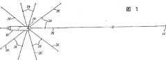
图1是本发明的一种由多根到海底的锚定腿系留的石油或气体储存船的俯视示意图;Fig. 1 is a schematic top view of an oil or gas storage ship moored by multiple anchoring legs to the seabed of the present invention;
图2是图1船的剖面示意图,它示出一固定于船并延伸到在海床的一个锚上的锚定腿;Figure 2 is a schematic cross-sectional view of the ship of Figure 1 showing an anchoring leg secured to the ship and extending to an anchor on the seabed;
图3是图2的局部放大图,它进一步示出锚定腿和连接锚定腿的转台的特征;以及Figure 3 is a partial enlarged view of Figure 2 further illustrating the features of the anchoring legs and the turntable connecting the anchoring legs; and
图4是具有朝下延伸的井管的储存船的转台的剖视图,它还示出了连接于转台的锚定腿。发明描述Figure 4 is a cross-sectional view of the turret of a storage vessel with downwardly extending well tubing, also showing the anchoring legs attached to the turret. Description of the invention
参阅附图,所示的储存石油或气体的船10浮在洋的表面或海面12上。船10有一位于海面12下的龙骨(keel)14。海床或海底用编号16表示。船10有一在其宽度中心的月池或井18。用编号20表示的转台安装在井18内可以绕一垂直轴线转动,这将在下面进一步说明。Referring to the drawings, an oil or
软的井管22从转台20向下伸到海底16并连接于用编号24表示的生产井,以把石油或气体输送到储存船10作暂时储存。井管22是软的其长度足以允许船10进行预定的移动而不会对井管22有任何破坏。Flexible well tubing 22 extends from
总的用编号26表示的多个锚定腿围绕转台20间隔设置(在较佳实施例中以36°的圆弧间隔),如图1所示。各锚定腿26基本上相同,包括多个连接起来的链条和钢丝绳。各锚定腿26长度的中间连接着一个用编号28表示的浸没式支承浮子,它是本发明的一个重要部分。浸没式支承浮子28的尺寸比较大,其排水量约50公吨,至少约20公吨。在大多数应用情况下35公吨左右的支承浮子28已足够使用。在支承浮子28与船10之间形成的悬垂链的链条和钢丝绳的重量以及在浮子28与海底16之间的钢丝绳和链条的重量使支承浮子28浸没于水中。支承浮子28的深度取决于浮子28的向上的浮力平衡链条和钢丝绳向下的力的平衡点。例如,浮子28的平衡深度可以是75米,而一般浸没深度的范围在约35至150米之间。A plurality of anchoring legs, generally indicated at 26, are spaced around the turntable 20 (in the preferred embodiment at 36[deg.] arc intervals) as shown in FIG. Each anchoring
支承浮子28的深度和水平位置还被设计成当船留在位置上时,即使在船10遭受能预料到的最恶劣的暴风雨或其他环境条件下也能避免锚定腿26与井管22之间的任何接触。当支承浮子28在水中下沉时,由于位于海底16的锚定腿量的增加使得作用在这种浮子28的负荷减少。The depth and horizontal position of the
锚定腿26的链条和钢丝绳向下的重量和所希望的浮子28的浸没深度总的确定了浮子28的大小。当然,还取决于其他因素如船的大小和类型、锚定腿的数量和25、50、75或100年间的环境状况。环境状况则包括水流、波和风的情况以及水深和可能的浮冰情况。可对浮子28增加镇重物以提供形成所需平衡深度所需要的精确的浮力。浮子28的平衡深度也将取决于锚定腿是负载最大锚定腿还是负载最小的锚定腿,而这取决于船10的拉力。最大负载锚定腿与最小负载锚定腿的浸没式支承浮子的深度差在20至25米之间,例如主要取决于锚定腿的长度。The downward weight of the chain and wire rope anchoring the
各锚定腿26包括一连接于转台20的短的链条30和一连接在链条30与浸没浮子28之间的钢丝绳32以在船10与浮子28之间形成一悬垂链。一钢丝绳34从浮子28径向朝外朝下向海底16延伸,它在海底16上面的编号为36的地方连接于沿着海底16表面延伸的一链条38。链条38在编号40处连接于钢丝绳42,该钢丝绳42沿海床16延伸至在离开浮子28径向最远处埋入海床的锚44。Each anchoring
作为一个推荐系统的锚定腿的设计参数的一个例子,一140,000载重吨位的船有十根锚定腿26,如图1所示,其中链条30的长度约为5米,钢丝绳32的长度约为200米,钢丝绳34的长度约为275米,链条38的长度约为325米,钢丝绳42的长度约为1,000米。因此,在转台20与支承浮子28之间的由链条30和钢丝绳32构成的锚定索链长度约为205米长,以便使浮子28足以与井管22水平分开并在转台20与浮子28之间提供所需的悬垂链。As an example of the design parameters of the anchoring legs of a proposed system, a 140,000 deadweight tonnage ship has ten anchoring
如图4所示,转台20在用编号46表示的上支承组件和用编号48表示的下支承组件的绕基本上垂直的轴线旋转。支承组件46和48可以是一种合适的设计,例如揭示在S.N.07/767,026、日期为1991年9月27日、名称为“可分离的转台系留系统”的专利申请中的那种,该申请的公开内容援引在此作参考之用。链条30容纳在固定于转台20上的一支架52的管套50内。然后链条30伸出管套50,其上端锚定于转台20上的锚定支撑件54。安装在转台20内的井管导向管60连接于井管22并向上通过转台20延伸以连接于合适的管道,以便在储存船10内储存碳氢化合物或可把碳氢化合物输送到另外相邻的船,如本领域的技术人员所熟知的那样。As shown in FIG. 4 , the
支承浮子28有助于对船10的移动提供一恢复力,因为各锚定腿26的大部分轴向力形成了水平分量,该水平分量提供一相当大的通过链条30作用的转矩以帮助转台20的旋转。由于锚定腿26施加于转台20的这些相当大的转矩,就不需要另外有一单独的转台驱动机构。Supporting the
因而很显然,对于上述结构来讲,作用于转台20的锚定索链的垂直力不大,当船在海水的力的作用下横向移动或旋转时,垂直力可使转台20束缚于其支承件。而在本发明中,如前所述,有了通过连接于横向延伸的浮子28的链条30和钢丝绳32所作用于转台20的基本水平的力,转台上的垂直负载大大减小,从而转台将不会在垂直负载的作用下束缚于船,船10能绕基本水平系留的转台方便地摆动。It is thus clear that, for the structure described above, the vertical force acting on the anchoring cables of the
系留的船相对于通过转台连接的井管22的稳定性,通过相当长的且基本上径向延伸的从海床连接到浮子28的钢丝绳和链条而进一步得到增强,如图1所示。沿着锚定腿延伸的钢丝绳和链条30,34,40和42的主要的垂直力都作用于较大的浮子28上,事实上通过它们径向延伸,还消除了浮子的任何径向的朝内运动,从而,浮子使转台和船相对于井管得到稳定。The stability of the moored vessel relative to the well casing 22 connected by the turret is further enhanced by relatively long and substantially radially extending wire ropes and chains connected from the seabed to the
从图2和3可清楚地看出,较大的浮子28的这种锚定腿的布置使得它在水平方向离开井管22相当长的一段距离,而且浸没的角度比较浅,与海面约为30°,或者说,与转台的垂直轴线,也就是从井口24开始的井管22之间的角度约为60°,从而,使得浮子和锚定索链不仅与从井口24开始的基本垂直的井管而且与传统的相当软的如图所示从一较远的海底井口延伸的井管也都能很好地分开来。It can be seen clearly from Figures 2 and 3 that the arrangement of the anchoring legs of the
上面虽然详细描述了本发明的一较佳实施例,但很显然,本领域的技术人员可以对它进行改变和适应性修改。然而完全可以理解是,这些改变和适应性修改均应落在如下面权利要求书所述的本发明的基本精神和范围之内。Although a preferred embodiment of the present invention has been described in detail above, it is obvious that those skilled in the art can make changes and adaptive modifications to it. It is however fully understood that such changes and adaptations are within the essential spirit and scope of the invention as set forth in the following claims.
Claims (13)
Applications Claiming Priority (2)
| Application Number | Priority Date | Filing Date | Title |
|---|---|---|---|
| US16249693A | 1993-12-03 | 1993-12-03 | |
| US08/162,496 | 1993-12-03 |
Publications (2)
| Publication Number | Publication Date |
|---|---|
| CN1141021Atrue CN1141021A (en) | 1997-01-22 |
| CN1053154C CN1053154C (en) | 2000-06-07 |
Family
ID=22585864
Family Applications (1)
| Application Number | Title | Priority Date | Filing Date |
|---|---|---|---|
| CN94194792AExpired - Fee RelatedCN1053154C (en) | 1993-12-03 | 1994-11-29 | Method and system for mooring floating storage vessels |
Country Status (10)
| Country | Link |
|---|---|
| US (2) | US5678503A (en) |
| JP (1) | JP2796890B2 (en) |
| CN (1) | CN1053154C (en) |
| AU (1) | AU678662B2 (en) |
| BR (1) | BR9408249A (en) |
| CA (1) | CA2178074A1 (en) |
| NO (1) | NO962284L (en) |
| NZ (1) | NZ277164A (en) |
| RU (1) | RU2145289C1 (en) |
| WO (1) | WO1995015277A1 (en) |
Cited By (2)
| Publication number | Priority date | Publication date | Assignee | Title |
|---|---|---|---|---|
| CN104229074A (en)* | 2008-11-03 | 2014-12-24 | 斯塔特伊石油公司 | Disconnectable production dock (DPD) for turret free disconnectable weather vaning FPSO |
| CN106043599A (en)* | 2016-07-26 | 2016-10-26 | 常州市山峰新能源科技有限公司 | Floating device traction protection mechanism |
Families Citing this family (16)
| Publication number | Priority date | Publication date | Assignee | Title |
|---|---|---|---|---|
| RU2145289C1 (en)* | 1993-12-03 | 2000-02-10 | Фмк Корпорейшн | Method and system of mooring tank ship |
| US6169801B1 (en) | 1998-03-16 | 2001-01-02 | Midcom, Inc. | Digital isolation apparatus and method |
| ID28208A (en) | 1998-03-27 | 2001-05-10 | Single Buoy Moorings | CONSTRUCTION OF FLOATING HOLDERS |
| EP0962384A1 (en)* | 1998-06-05 | 1999-12-08 | Single Buoy Moorings Inc. | Loading arrangement |
| US6453838B1 (en)* | 2000-10-20 | 2002-09-24 | Ocean Production Technology, Llc | Turret-less floating production ship |
| US6494271B2 (en)* | 2001-04-25 | 2002-12-17 | Exxonmobil Upstream Research Company | Offshore floating production method |
| US6692192B2 (en)* | 2002-05-03 | 2004-02-17 | Single Buoy Moorings Inc. | Spread moored midship hydrocarbon loading and offloading system |
| MXPA05003033A (en)* | 2002-09-19 | 2005-05-27 | Polymer Group Inc | Nonwoven industrial fabrics with improved barrier properties. |
| US8186170B2 (en)* | 2007-05-29 | 2012-05-29 | Sofec, Inc. | Floating LNG regasification facility with LNG storage vessel |
| US7770532B2 (en)* | 2007-06-12 | 2010-08-10 | Single Buoy Moorings, Inc. | Disconnectable riser-mooring system |
| EP2285666B1 (en)* | 2008-05-19 | 2012-01-04 | Single Buoy Moorings Inc. | Disconnectable turret mooring system with a weighted riser-supporting buoy |
| ES2435315T3 (en)* | 2011-02-23 | 2013-12-18 | Bluewater Energy Services B.V. | Detachable mooring system and method to disconnect or reconnect it |
| RU2518774C1 (en)* | 2013-04-16 | 2014-06-10 | Открытое акционерное общество "Пермский завод "Машиностроитель" | Mandrel for application of resilient coat on housing inner surface |
| WO2016159856A1 (en)* | 2015-04-02 | 2016-10-06 | W4P Waves4Power Ab | Wave energy converter with mooring system comprising buoyant elements |
| CN108951550A (en)* | 2018-08-07 | 2018-12-07 | 霍山别他山电子商务有限公司 | A kind of Boat Rafting Tours quickwater safety device |
| RU2714994C1 (en)* | 2019-05-06 | 2020-02-21 | Федеральное государственное бюджетное образовательное учреждение высшего образования "Государственный морской университет имени адмирала Ф.Ф. Ушакова" | Method of controlling a ship when performing mooring operation to a shipboard of a partner ship |
Family Cites Families (10)
| Publication number | Priority date | Publication date | Assignee | Title |
|---|---|---|---|---|
| US2986888A (en)* | 1958-06-25 | 1961-06-06 | California Research Corp | Method and apparatus for anchoring marine structures |
| US3703151A (en)* | 1970-09-04 | 1972-11-21 | Ocean Design Eng Corp | Biased taut line mooring system |
| US4509448A (en)* | 1983-10-13 | 1985-04-09 | Sonat Offshore Drilling Inc. | Quick disconnect/connect mooring method and apparatus for a turret moored drillship |
| US4604961A (en)* | 1984-06-11 | 1986-08-12 | Exxon Production Research Co. | Vessel mooring system |
| NO160914C (en)* | 1986-03-24 | 1989-06-14 | Svensen Niels Alf | BUILDING LOADING SYSTEM FOR OFFSHORE PETROLEUM PRODUCTION. |
| NL194724C (en)* | 1988-12-02 | 2003-01-07 | Seaflow Systems Res N V | Device for extracting, storing and removing oil from the seabed. |
| US5044297A (en)* | 1990-09-14 | 1991-09-03 | Bluewater Terminal Systems N.V. | Disconnectable mooring system for deep water |
| GB9025155D0 (en)* | 1990-11-20 | 1991-01-02 | Bluewater Terminal Systems N W | Improvements in or relating to vessel anchor systems |
| US5159891A (en)* | 1991-08-22 | 1992-11-03 | Shell Offshore Inc. | Adjustable boat mooring system for a flexibly-supported tension leg platform |
| RU2145289C1 (en)* | 1993-12-03 | 2000-02-10 | Фмк Корпорейшн | Method and system of mooring tank ship |
- 1994
- 1994-11-29RURU96115003/28Apatent/RU2145289C1/ennot_activeIP Right Cessation
- 1994-11-29AUAU12101/95Apatent/AU678662B2/ennot_activeCeased
- 1994-11-29NZNZ277164Apatent/NZ277164A/enunknown
- 1994-11-29BRBR9408249Apatent/BR9408249A/ennot_activeIP Right Cessation
- 1994-11-29JPJP7515645Apatent/JP2796890B2/ennot_activeExpired - Fee Related
- 1994-11-29CNCN94194792Apatent/CN1053154C/ennot_activeExpired - Fee Related
- 1994-11-29CACA002178074Apatent/CA2178074A1/ennot_activeAbandoned
- 1994-11-29WOPCT/US1994/013277patent/WO1995015277A1/enactiveApplication Filing
- 1996
- 1996-02-13USUS08/599,859patent/US5678503A/ennot_activeExpired - Fee Related
- 1996-06-03NONO962284Apatent/NO962284L/ennot_activeApplication Discontinuation
- 1997
- 1997-08-04USUS08/905,854patent/US5873395A/ennot_activeExpired - Fee Related
Cited By (2)
| Publication number | Priority date | Publication date | Assignee | Title |
|---|---|---|---|---|
| CN104229074A (en)* | 2008-11-03 | 2014-12-24 | 斯塔特伊石油公司 | Disconnectable production dock (DPD) for turret free disconnectable weather vaning FPSO |
| CN106043599A (en)* | 2016-07-26 | 2016-10-26 | 常州市山峰新能源科技有限公司 | Floating device traction protection mechanism |
Also Published As
| Publication number | Publication date |
|---|---|
| NO962284L (en) | 1996-08-02 |
| CA2178074A1 (en) | 1995-06-08 |
| CN1053154C (en) | 2000-06-07 |
| JP2796890B2 (en) | 1998-09-10 |
| WO1995015277A1 (en) | 1995-06-08 |
| NO962284D0 (en) | 1996-06-03 |
| US5678503A (en) | 1997-10-21 |
| NZ277164A (en) | 1997-05-26 |
| BR9408249A (en) | 1997-05-27 |
| RU2145289C1 (en) | 2000-02-10 |
| AU678662B2 (en) | 1997-06-05 |
| AU1210195A (en) | 1995-06-19 |
| JPH09506570A (en) | 1997-06-30 |
| US5873395A (en) | 1999-02-23 |
Similar Documents
| Publication | Publication Date | Title |
|---|---|---|
| CN1100698C (en) | System for loading ships at sea | |
| CN1141021A (en) | Method and system for mooring floating storage vessels | |
| US9032892B2 (en) | Mooring system and connector assembly | |
| US5893334A (en) | Method and apparatus for mooring floating storage vessels | |
| US4966495A (en) | Semisubmersible vessel with captured constant tension buoy | |
| CN1072153C (en) | Shallow draft floating off shore drilling/producing structure | |
| US8480334B2 (en) | Hybrid riser systems and methods | |
| US6210075B1 (en) | Spar system | |
| KR20100124733A (en) | Floating support having a reel including roller bearings outside the water | |
| US4472079A (en) | Articulated pipe discharge ramp | |
| US11319036B2 (en) | Mooring systems and processes for using same | |
| US20060056918A1 (en) | Riser system connecting two fixed underwater installations to a floating surface unit | |
| WO2000027692A1 (en) | Device for positioning of vessels | |
| Rutkowski | A comparison between conventional buoy mooring CBM, single point mooring SPM and single anchor loading sal systems considering the hydro-meteorological condition limits for safe ship’s operation offshore | |
| US3481294A (en) | Anchored riser pipe mooring system for drilling vessel | |
| GB2096963A (en) | An off-shore mooring system | |
| CN212135994U (en) | Novel deepwater umbilical cable linear configuration | |
| CN1088023C (en) | Submerged Suspension Anchor Boom Mooring Buoy | |
| WO2002047970A1 (en) | Low motion semisubmersible floating production system | |
| JP2024509197A (en) | Split mooring system and method for ships | |
| Kok et al. | Marine installation of FPSOs | |
| d’Hautefeuille | Floating Production Storage and Offloading: Disconnectable or Not? | |
| JPS5948279B2 (en) | flexible riser device |
Legal Events
| Date | Code | Title | Description |
|---|---|---|---|
| C06 | Publication | ||
| PB01 | Publication | ||
| C10 | Entry into substantive examination | ||
| SE01 | Entry into force of request for substantive examination | ||
| C14 | Grant of patent or utility model | ||
| GR01 | Patent grant | ||
| ASS | Succession or assignment of patent right | Owner name:FMC TECHNOLOGY CO., LTD. Free format text:FORMER OWNER: FMC CORP. Effective date:20061201 | |
| C41 | Transfer of patent application or patent right or utility model | ||
| TR01 | Transfer of patent right | Effective date of registration:20061201 Address after:Texas in the United States Patentee after:FMC Europe S. A. Address before:Illinois Instrunment Patentee before:FMC Corp. | |
| C17 | Cessation of patent right | ||
| CF01 | Termination of patent right due to non-payment of annual fee | Granted publication date:20000607 Termination date:20111129 |