CN114064373B - Test system, test method, test device and test equipment for USB platelet - Google Patents
Test system, test method, test device and test equipment for USB plateletDownload PDFInfo
- Publication number
- CN114064373B CN114064373BCN202210051770.3ACN202210051770ACN114064373BCN 114064373 BCN114064373 BCN 114064373BCN 202210051770 ACN202210051770 ACN 202210051770ACN 114064373 BCN114064373 BCN 114064373B
- Authority
- CN
- China
- Prior art keywords
- connector
- usb
- test
- microprocessor
- pin
- Prior art date
- Legal status (The legal status is an assumption and is not a legal conclusion. Google has not performed a legal analysis and makes no representation as to the accuracy of the status listed.)
- Active
Links
Images


Classifications
- G—PHYSICS
- G06—COMPUTING OR CALCULATING; COUNTING
- G06F—ELECTRIC DIGITAL DATA PROCESSING
- G06F11/00—Error detection; Error correction; Monitoring
- G06F11/22—Detection or location of defective computer hardware by testing during standby operation or during idle time, e.g. start-up testing
- G06F11/2205—Detection or location of defective computer hardware by testing during standby operation or during idle time, e.g. start-up testing using arrangements specific to the hardware being tested
- G06F11/221—Detection or location of defective computer hardware by testing during standby operation or during idle time, e.g. start-up testing using arrangements specific to the hardware being tested to test buses, lines or interfaces, e.g. stuck-at or open line faults
- G—PHYSICS
- G06—COMPUTING OR CALCULATING; COUNTING
- G06F—ELECTRIC DIGITAL DATA PROCESSING
- G06F11/00—Error detection; Error correction; Monitoring
- G06F11/22—Detection or location of defective computer hardware by testing during standby operation or during idle time, e.g. start-up testing
- G06F11/2273—Test methods
Landscapes
- Engineering & Computer Science (AREA)
- General Engineering & Computer Science (AREA)
- Theoretical Computer Science (AREA)
- Computer Hardware Design (AREA)
- Quality & Reliability (AREA)
- Physics & Mathematics (AREA)
- General Physics & Mathematics (AREA)
- Tests Of Electronic Circuits (AREA)
Abstract
Translated fromChinese
Description
Translated fromChinese技术领域technical field
本申请涉及设备测试技术领域,特别是涉及一种USB小板的测试系统、测试方法、测试装置、测试设备及计算机可读存储介质。The present application relates to the technical field of equipment testing, and in particular, to a testing system, testing method, testing device, testing equipment and computer-readable storage medium of a USB small board.
背景技术Background technique
USB,是英文Universal Serial Bus(通用串行总线)的缩写,是一个外部总线标准,用于规范电脑与外部设备的连接和通讯。是应用在PC领域的接口技术。USB小板是一种应用于计算机设备中利用排线与设备主板连接的单独的USB电路板,用于扩展连接USB设备。故USB小板上通常包括用于连接设备主板的主板连接器以及与主板连接器连接的USB接口。USB, short for Universal Serial Bus (Universal Serial Bus) in English, is an external bus standard used to regulate the connection and communication between computers and external devices. It is an interface technology applied in the PC field. A small USB board is a separate USB circuit board that is used in computer equipment to connect with the main board of the equipment using a flat cable, and is used to expand and connect USB devices. Therefore, the USB small board usually includes a mainboard connector for connecting to the mainboard of the device and a USB interface connected with the mainboard connector.
为对USB小板进行质量测试,现有测试方案通常为搭建一台个人计算机(PC)工装,将被测USB小板的主板连接器连接到个人计算机主板上的对应位置,再将被测USB小板的USB接口与USB设备(如鼠标)连接,然后开机进行功能测试。In order to test the quality of the USB small board, the existing test scheme is usually to build a personal computer (PC) tooling, connect the motherboard connector of the tested USB small board to the corresponding position on the PC motherboard, and then connect the tested USB small board to the corresponding position on the main board of the personal computer. Connect the USB interface of the small board to a USB device (such as a mouse), and then power on for functional testing.
然而,基于这种PC工装,需要等待较长时间进入操作系统测试界面,测试结束后关机,整个测试流程大概需要220s,测试效率较低。且基于该PC工装对USB小板进行测试的过程中,有时会出现带电插拔的情景,会导致USB小板功能异常。However, based on this kind of PC tooling, it is necessary to wait for a long time to enter the operating system test interface, and shut down after the test. The entire test process takes about 220s, and the test efficiency is low. And in the process of testing the USB small board based on the PC tooling, sometimes a live plugging and unplugging situation occurs, which will cause the USB small board to function abnormally.
发明内容SUMMARY OF THE INVENTION
本申请的目的是提供一种USB小板的测试系统、测试方法、测试装置、测试设备及计算机可读存储介质,提供一个用时更短且无带电插拔场景的USB小板测试方案,提高测试效率同时避免测试过程对产品造成损坏,提高USB小板产品质量。The purpose of this application is to provide a test system, test method, test device, test equipment and computer-readable storage medium for a USB small board, provide a USB small board test solution with a shorter time and no live plugging and unplugging scenarios, and improve the test results. Efficiency at the same time avoids damage to the product during the testing process, and improves the quality of the USB small board product.
为解决上述技术问题,本申请提供一种USB小板的测试系统,包括:第一连接器和微处理器;In order to solve the above technical problems, the present application provides a test system for a USB small board, including: a first connector and a microprocessor;
其中,所述第一连接器的第一端与所述微处理器连接,所述第一连接器的第二端用于连接被测USB小板的主板连接器的第一端,所述主板连接器的第二端与所述被测USB小板的USB接口的第一端连接;The first end of the first connector is connected to the microprocessor, and the second end of the first connector is used to connect to the first end of the mainboard connector of the USB small board under test. The mainboard The second end of the connector is connected with the first end of the USB interface of the tested USB small board;
所述微处理器用于在所述第一连接器与所述主板连接器连接后,在所述被测USB小板的USB接口的第二端处于悬空状态时,通过所述第一连接器对所述主板连接器的各引脚两两为一组进行不同电平赋值,并在检测到存在实际电平与赋值电平不同的所述引脚时确认所述被测USB小板存在引脚间短路故障;The microprocessor is used for, after the first connector is connected with the mainboard connector, when the second end of the USB interface of the USB small board under test is in a suspended state, the first connector is used for pairing. The pins of the motherboard connector are assigned different levels in pairs, and when it is detected that there are said pins whose actual level is different from the assigned level, it is confirmed that the tested USB small board has pins. short circuit fault;
所述微处理器还用于在所述第一连接器与所述主板连接器连接后,在所述被测USB小板的USB接口的第二端处于接地状态时,通过所述第一连接器将所述主板连接器的各所述引脚赋为高电平,并在检测到所述主板连接器的各所述引脚均根据所述USB接口的第二端的电平发生变化时,确认所述被测USB小板的USB接口有效。The microprocessor is also used for connecting the first connector to the motherboard connector, when the second end of the USB interface of the USB small board under test is in a grounded state, through the first connection. The device assigns each of the described pins of the mainboard connector to a high level, and when detecting that each of the described pins of the mainboard connector changes according to the level of the second end of the USB interface, Confirm that the USB interface of the tested USB board is valid.
可选的,还包括第一切换开关和USB公头;Optionally, it also includes a first switch and a USB male header;
其中,所述USB公头的第一端用于连接所述USB接口的第二端,所述USB公头的第二端接地;所述第一切换开关设于所述USB公头的第二端与地之间,所述第一切换开关的控制端与所述微处理器连接;Wherein, the first end of the USB male head is used to connect the second end of the USB interface, and the second end of the USB male head is grounded; the first switch is arranged on the second end of the USB male head Between the terminal and the ground, the control terminal of the first switch is connected to the microprocessor;
所述微处理器还用于控制所述第一切换开关断开以使所述USB接口的第二端处于悬空状态,控制所述第一切换开关闭合以使所述USB接口的第二端处于接地状态。The microprocessor is further configured to control the first switch to be turned off so that the second end of the USB interface is in a floating state, and to control the first switch to be closed so that the second end of the USB interface is in a floating state. ground state.
可选的,所述被测USB小板还包括小板指示灯;所述小板指示灯的阳极与所述主板连接器的电源引脚连接,所述小板指示灯的阴极与所述主板连接器的指示灯引脚连接;Optionally, the USB small board under test also includes a small board indicator light; the anode of the small board indicator light is connected to the power supply pin of the main board connector, and the cathode of the small board indicator light is connected to the main board. The indicator pin of the connector is connected;
测试系统还包括第二切换电路;The test system further includes a second switching circuit;
所述第二切换电路的控制端与所述微处理器连接,所述第二切换电路的静触点与所述第一连接器的电源引脚连接,所述第二切换电路的第一动触点与直流电源连接,所述第二切换电路的第二动触点与所述微处理器的第一输入输出引脚连接;The control terminal of the second switching circuit is connected to the microprocessor, the static contact of the second switching circuit is connected to the power supply pin of the first connector, and the first moving The contact is connected with the DC power supply, and the second movable contact of the second switching circuit is connected with the first input and output pins of the microprocessor;
所述微处理器还用于在所述第一连接器与所述主板连接器连接后,控制所述第二切换电路切换至所述第一动触点,通过所述第一连接器将所述主板连接器的指示灯引脚赋为低电平,以根据所述小板指示灯的亮灭对所述小板指示灯所在支路进行有效性评估。The microprocessor is also used to control the second switching circuit to switch to the first movable contact after the first connector is connected to the motherboard connector, and connect all the contacts through the first connector. The indicator pin of the mainboard connector is assigned a low level, so as to evaluate the validity of the branch where the indicator light of the small board is located according to the on/off of the indicator light of the small board.
可选的,所述第二切换电路具体包括:第一电阻、第一NPN三极管和继电器;Optionally, the second switching circuit specifically includes: a first resistor, a first NPN transistor and a relay;
其中,所述第一电阻的第一端连接直流电源,所述第一电阻的第二端与所述第一NPN三极管的集电极连接,所述第一NPN三极管的发射极与所述继电器的控制端连接,所述第一NPN三极管的基极与所述微处理器的第二输入输出引脚连接,所述继电器的静触点与所述第一连接器的电源引脚连接,所述继电器的第一动触点与直流电源连接,所述继电器的第二动触点与所述微处理器的第一输入输出引脚连接。The first end of the first resistor is connected to a DC power supply, the second end of the first resistor is connected to the collector of the first NPN triode, and the emitter of the first NPN triode is connected to the relay's The control terminal is connected, the base of the first NPN transistor is connected with the second input and output pins of the microprocessor, the static contact of the relay is connected with the power supply pin of the first connector, and the The first movable contact of the relay is connected with the DC power supply, and the second movable contact of the relay is connected with the first input and output pins of the microprocessor.
可选的,还包括与所述微处理器连接的用于接收测试命令的输入模块。Optionally, it also includes an input module connected to the microprocessor for receiving test commands.
可选的,还包括与所述微处理器连接的用于输出测试结果的输出模块。Optionally, it also includes an output module connected to the microprocessor for outputting test results.
为解决上述技术问题,本申请还提供一种USB小板的测试方法,应用于微处理器,所述微处理器与第一连接器的第一端连接,所述第一连接器的第二端用于连接被测USB小板的主板连接器的第一端,所述主板连接器的第二端与所述被测USB小板的USB接口的第一端连接;In order to solve the above technical problems, the present application also provides a test method for a USB small board, which is applied to a microprocessor, the microprocessor is connected to the first end of the first connector, and the second end of the first connector is connected to the first end of the first connector. The end is used to connect the first end of the mainboard connector of the tested USB small board, and the second end of the mainboard connector is connected with the first end of the USB interface of the tested USB small board;
测试方法包括:Test methods include:
在所述第一连接器与所述主板连接器连接后,在所述被测USB小板的USB接口的第二端处于悬空状态时,通过所述第一连接器对所述主板连接器的各引脚两两为一组进行不同电平赋值,并在检测到存在实际电平与赋值电平不同的所述引脚时确认所述被测USB小板存在引脚间短路故障;After the first connector is connected to the mainboard connector, when the second end of the USB interface of the USB small board under test is in a suspended state, the connection between the mainboard connector and the Each pin is assigned a different level in pairs, and when it is detected that there is a described pin whose actual level is different from the assigned level, it is confirmed that the tested USB small board has a short-circuit fault between pins;
在所述第一连接器与所述主板连接器连接后,在所述被测USB小板的USB接口的第二端处于接地状态时,通过所述第一连接器将所述主板连接器的各所述引脚赋为高电平,并在检测到所述主板连接器的各所述引脚均根据所述USB接口的第二端的电平发生变化时,确认所述被测USB小板的USB接口有效。After the first connector is connected to the mainboard connector, when the second end of the USB interface of the USB small board under test is in a grounded state, the first connector is used to connect the mainboard connector to the ground. Each of the pins is assigned a high level, and when it is detected that each of the pins of the motherboard connector changes according to the level of the second end of the USB interface, it is confirmed that the tested USB small board The USB interface is valid.
为解决上述技术问题,本申请还提供一种USB小板的测试装置,应用于微处理器,所述微处理器与第一连接器的第一端连接,所述第一连接器的第二端用于连接被测USB小板的主板连接器的第一端,所述主板连接器的第二端与所述被测USB小板的USB接口的第一端连接;In order to solve the above technical problems, the present application also provides a test device for a USB small board, which is applied to a microprocessor, the microprocessor is connected to the first end of the first connector, and the second end of the first connector is connected. The end is used to connect the first end of the mainboard connector of the tested USB small board, and the second end of the mainboard connector is connected with the first end of the USB interface of the tested USB small board;
测试装置包括:The test setup includes:
短路测试单元,用于在所述第一连接器与所述主板连接器连接后,在所述被测USB小板的USB接口的第二端处于悬空状态时,通过所述第一连接器对所述主板连接器的各引脚两两为一组进行不同电平赋值,并在检测到存在实际电平与赋值电平不同的所述引脚时确认所述被测USB小板存在引脚间短路故障;The short-circuit test unit is used for, after the first connector is connected with the mainboard connector, when the second end of the USB interface of the tested USB small board is in a floating state, the first connector The pins of the motherboard connector are assigned different levels in pairs, and when it is detected that there are said pins whose actual level is different from the assigned level, it is confirmed that the tested USB small board has pins. short circuit fault;
断路测试单元,用于在所述第一连接器与所述主板连接器连接后,在所述被测USB小板的USB接口的第二端处于接地状态时,通过所述第一连接器将所述主板连接器的各所述引脚赋为高电平,并在检测到所述主板连接器的各所述引脚均根据所述USB接口的第二端的电平发生变化时,确认所述被测USB小板的USB接口有效。The circuit breaking test unit is used for, after the first connector is connected with the main board connector, when the second end of the USB interface of the tested USB small board is in a grounded state, through the first connector Each of the pins of the mainboard connector is assigned a high level, and when it is detected that each of the pins of the mainboard connector changes according to the level of the second end of the USB interface, it is confirmed that all the pins of the mainboard connector are changed. The USB interface of the tested USB board is valid.
为解决上述技术问题,本申请还提供一种USB小板的测试设备,包括:In order to solve the above-mentioned technical problems, the present application also provides a test equipment for a USB small board, including:
存储器,用于存储计算机程序;memory for storing computer programs;
处理器,用于执行所述计算机程序,所述计算机程序被所述处理器执行时实现如上述USB小板的测试方法的步骤。The processor is configured to execute the computer program, and when the computer program is executed by the processor, the steps of the above-mentioned USB small board testing method are implemented.
为解决上述技术问题,本申请还提供一种计算机可读存储介质,其上存储有计算机程序,所述计算机程序被处理器执行时实现如上述USB小板的测试方法的步骤。In order to solve the above technical problems, the present application also provides a computer-readable storage medium on which a computer program is stored, and when the computer program is executed by a processor, the steps of the above-mentioned USB small board testing method are implemented.
本申请所提供的USB小板的测试系统,包括用于连接被测USB小板的主板连接器的第一连接器,以及与所述第一连接器连接的微处理器,该主板连接器的第二端与被测USB小板的USB接口的第一端连接;该微处理器在第一连接器与主板连接器连通后,在被测USB小板的USB接口的第二端处于悬空状态时,通过第一连接器对主板连接器的各引脚两两为一组进行不同电平赋值,以根据主板连接器引脚的电平变化进行被测USB小板的连接器引脚间短路测试;该微处理器还在被测USB小板的USB接口的第二端处于接地状态时,通过第一连接器将主板连接器的各引脚赋为高电平,并通过检测主板连接器的各引脚的电平变化来对被测USB小板进行USB接口连通性测试。本申请所提供的基于微处理器搭建的USB小板的测试系统相较于现有的PC工装,不仅可以在更短的时间内进入测试环境完成测试,且在测试过程中不存在带电插拔状况,避免了带电插拔的问题,从而不仅提高了测试效率,还避免了测试过程对产品造成损坏,提高了USB小板产品质量。The test system for a USB small board provided by the present application includes a first connector for connecting to the mainboard connector of the USB small board under test, and a microprocessor connected to the first connector. The mainboard connector has a The second end is connected to the first end of the USB interface of the USB small board under test; after the first connector is connected with the main board connector, the microprocessor is in a floating state when the second end of the USB interface of the small USB board under test is connected When the first connector is used, the pins of the motherboard connector are assigned different levels in pairs, so as to short-circuit between the connector pins of the USB small board under test according to the level change of the motherboard connector pins. Test; when the second end of the USB interface of the USB small board under test is in a grounded state, the microprocessor assigns each pin of the main board connector to a high level through the first connector, and detects the main board connector through the first connector. The level change of each pin is used to test the USB interface connectivity of the tested USB board. Compared with the existing PC tooling, the USB small board test system based on the microprocessor provided by this application can not only enter the test environment to complete the test in a shorter time, but also has no live plugging and unplugging during the test process. It avoids the problem of live plugging and unplugging, which not only improves the test efficiency, but also avoids damage to the product during the test process, and improves the product quality of the USB small board.
本申请还提供一种USB小板的测试方法、测试装置、测试设备及计算机可读存储介质,具有上述有益效果,在此不再赘述。The present application also provides a test method, test device, test equipment and computer-readable storage medium for a USB small board, which have the above beneficial effects, and will not be repeated here.
附图说明Description of drawings
为了更清楚的说明本申请实施例或现有技术的技术方案,下面将对实施例或现有技术描述中所需要使用的附图作简单的介绍,显而易见地,下面描述中的附图仅仅是本申请的一些实施例,对于本领域普通技术人员来讲,在不付出创造性劳动的前提下,还可以根据这些附图获得其他的附图。In order to illustrate the technical solutions of the embodiments of the present application or the prior art more clearly, the following briefly introduces the accompanying drawings that need to be used in the description of the embodiments or the prior art. Obviously, the drawings in the following description are only For some embodiments of the present application, for those of ordinary skill in the art, other drawings can also be obtained according to these drawings without any creative effort.
图1为本申请实施例提供的一种USB小板的测试系统的结构示意图;1 is a schematic structural diagram of a testing system for a USB small board provided by an embodiment of the present application;
图2(a)为一种USB小板的主板连接器的电路图;Figure 2(a) is a circuit diagram of a mainboard connector of a USB small board;
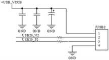
图2(b)为一种USB小板的第一USB接口的电路图;Figure 2(b) is a circuit diagram of a first USB interface of a USB small board;
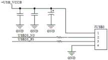
图2(c)为一种USB小板的第二USB接口的电路图;Figure 2(c) is a circuit diagram of a second USB interface of a USB small board;
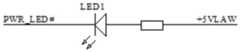
图2(d)为一种USB小板的小板指示灯的电路图;Figure 2(d) is a circuit diagram of a small board indicator light of a USB small board;
图3(a)为本申请实施例提供的微处理器的电路图;Fig. 3(a) is a circuit diagram of the microprocessor provided by the embodiment of the present application;
图3(b)为本申请实施例提供的第一连接器的电路图;Fig. 3(b) is a circuit diagram of the first connector provided by the embodiment of the present application;
图3(c)为本申请实施例提供的USB公头的电路图;FIG. 3(c) is a circuit diagram of a USB male header provided by an embodiment of the present application;
图3(d)为本申请实施例提供的第二切换电路的电路图;FIG. 3(d) is a circuit diagram of the second switching circuit provided by the embodiment of the present application;
图3(e)为本申请实施例提供的输入模块的电路图;FIG. 3(e) is a circuit diagram of an input module provided by an embodiment of the present application;
图3(f)为本申请实施例提供的输出模块的电路图;Fig. 3(f) is a circuit diagram of an output module provided by an embodiment of the present application;
图4为本申请实施例提供的一种USB小板的测试装置的结构示意图;4 is a schematic structural diagram of a testing device for a USB small board provided by an embodiment of the present application;
图5为本申请实施例提供的一种USB小板的测试设备的结构示意图;5 is a schematic structural diagram of a testing device for a USB small board provided by an embodiment of the present application;
其中,101为第一连接器,102为微处理器,103为第一切换开关,104为USB公头,105为第二切换电路,106为输入模块,107为输出模块。Wherein, 101 is a first connector, 102 is a microprocessor, 103 is a first switch, 104 is a USB male head, 105 is a second switch circuit, 106 is an input module, and 107 is an output module.
具体实施方式Detailed ways
本申请的核心是提供一种USB小板的测试系统、测试方法、测试装置、测试设备及计算机可读存储介质,提供一个用时更短且无带电插拔场景的USB小板测试方案,提高测试效率同时避免测试过程对产品造成损坏,提高USB小板产品质量。The core of the present application is to provide a test system, test method, test device, test equipment and computer-readable storage medium for a USB small board, and to provide a USB small board test solution with a shorter time and no live plugging and unplugging scenarios, so as to improve the test performance. Efficiency at the same time avoids damage to the product during the testing process, and improves the quality of the USB small board product.
下面将结合本申请实施例中的附图,对本申请实施例中的技术方案进行清楚、完整地描述,显然,所描述的实施例仅仅是本申请一部分实施例,而不是全部的实施例。基于本申请中的实施例,本领域普通技术人员在没有做出创造性劳动前提下所获得的所有其他实施例,都属于本申请保护的范围。The technical solutions in the embodiments of the present application will be clearly and completely described below with reference to the drawings in the embodiments of the present application. Obviously, the described embodiments are only a part of the embodiments of the present application, but not all of the embodiments. Based on the embodiments in the present application, all other embodiments obtained by those of ordinary skill in the art without creative efforts shall fall within the protection scope of the present application.
实施例一Example 1
图1为本申请实施例提供的一种USB小板的测试系统的结构示意图;图2(a)为一种USB小板的主板连接器的电路图;图2(b)为一种USB小板的第一USB接口的电路图;图2(c)为一种USB小板的第二USB接口的电路图;图2(d)为一种USB小板的小板指示灯的电路图;图3(a)为本申请实施例提供的微处理器的电路图;图3(b)为本申请实施例提供的第一连接器的电路图;图3(c)为本申请实施例提供的USB公头的电路图。1 is a schematic structural diagram of a test system for a USB small board provided by an embodiment of the application; FIG. 2( a ) is a circuit diagram of a mainboard connector of a USB small board; FIG. 2( b ) is a USB small board The circuit diagram of the first USB interface; Figure 2 (c) is a circuit diagram of the second USB interface of a USB small board; Figure 2 (d) is a circuit diagram of a small board indicator light of a USB small board; Figure 3 (a) ) the circuit diagram of the microprocessor provided by the embodiment of the application; FIG. 3(b) the circuit diagram of the first connector provided by the embodiment of the application; FIG. 3(c) the circuit diagram of the USB male connector provided by the embodiment of the application .
图2(a)、图2(b)、图2(c)和图2(d)提供了一种现有常见的USB小板的电路示意图,包括主板连接器JUSB1和两个USB接口,分别为第一USB接口JUSB2、第二USB接口JUSB3;JUSB2的引脚(USB20_N2、USB20_P2)、JUSB3的引脚(USB20_N3、USB20_P3)与主板连接器JUSB1的引脚对应连接,JUSB2的电源引脚(+USB_VCCB)、JUSB3的电源引脚(+USB_VCCB)与主板连接器JUSB1的+USB_VCCB引脚连接,主板连接器JUSB1的电源引脚(+5VLAW)用于连接主板上提供的直流电源。有些USB小板还设有用于提示连接状态的小板指示灯,即如图2(a)、图2(d)所示的,小板指示灯LED1的阳极与主板连接器JUSB1的电源引脚(+5VLAW)连接,小板指示灯LED1的阴极与主板连接器JUSB1的小板指示灯引脚(PWR_LED#)连接,在主板连接器JUSB1连接到设备主板上后,设备主板为主板连接器JUSB1的电源引脚(+5VLAW)提供直流电源,为主板连接器JUSB1的小板指示灯引脚(PWR_LED#)提供低电平,从而使小板指示灯LED1导通,以指示USB小板处于连接状态。Figure 2(a), Figure 2(b), Figure 2(c) and Figure 2(d) provide a schematic circuit diagram of an existing common USB small board, including the motherboard connector JUSB1 and two USB interfaces, respectively The first USB interface JUSB2 and the second USB interface JUSB3; the pins of JUSB2 (USB20_N2, USB20_P2) and the pins of JUSB3 (USB20_N3, USB20_P3) are correspondingly connected to the pins of the motherboard connector JUSB1, and the power pins of JUSB2 (+ USB_VCCB), the power pin (+USB_VCCB) of JUSB3 are connected to the +USB_VCCB pin of the main board connector JUSB1, and the power pin (+5VLAW) of the main board connector JUSB1 is used to connect the DC power supply provided on the main board. Some USB small boards also have a small board indicator for indicating the connection status, that is, as shown in Figure 2(a) and Figure 2(d), the anode of the small board indicator LED1 and the power pin of the main board connector JUSB1 (+5VLAW) connection, the cathode of the small board indicator LED1 is connected to the small board indicator pin (PWR_LED#) of the main board connector JUSB1, after the main board connector JUSB1 is connected to the device main board, the device main board is the main board connector JUSB1 The power supply pin (+5VLAW) of the main board provides DC power, and provides a low level for the small board indicator pin (PWR_LED#) of the main board connector JUSB1, so that the small board indicator LED1 is turned on to indicate that the USB small board is connected. state.
则对USB小板的测试主要包括USB接口连通性测试和的连接器引脚间短路测试。USB接口连通性测试为检测USB小板的主板连接器到各USB接口之间是否连通。连接器引脚间短路测试为检测主板连接器的引脚之间是否存在短路现象。如USB小板包括上述小板指示灯,则对USB小板的测试还可以包括对小板指示灯能够在USB小板连接上设备主板的直流电源后亮起进行测试。Then the test of the USB small board mainly includes the USB interface connectivity test and the short-circuit test between the connector pins. The USB interface connectivity test is to detect whether the connection between the mainboard connector of the USB small board and each USB interface is connected. The short-circuit test between the connector pins is to detect whether there is a short circuit between the pins of the motherboard connector. If the USB small board includes the above small board indicator light, the test on the USB small board may also include testing that the small board indicator light can be turned on after the USB small board is connected to the DC power supply of the device main board.
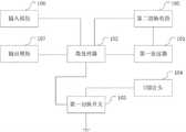
故针对USB小板的测试需求,如图1所示,本 申请实施例提供的USB小板的测试系统包括:第一连接器101和微处理器102(Micro Control Unit,又称单片微型计算机或单片机);Therefore, in view of the testing requirements of the USB small board, as shown in FIG. 1 , the testing system for the USB small board provided by the embodiment of the present application includes: a
其中,第一连接器101的第一端与微处理器102连接,第一连接器101的第二端用于连接被测USB小板的主板连接器的第一端,主板连接器的第二端与被测USB小板的USB接口的第一端连接;The first end of the
微处理器102用于在第一连接器101与主板连接器连接后,在被测USB小板的USB接口的第二端处于悬空状态时,通过第一连接器101对主板连接器的各引脚两两为一组进行不同电平赋值,并在检测到存在实际电平与赋值电平不同的引脚时确认被测USB小板存在引脚间短路故障;The
微处理器102还用于在第一连接器101与主板连接器连接后,在被测USB小板的USB接口的第二端处于接地状态时,通过第一连接器101将主板连接器的各引脚赋为高电平,并在检测到主板连接器的各引脚均根据USB接口的第二端的电平发生变化时,确认被测USB小板的USB接口有效。The
需要说明的是,本申请实施例中的直流电源可以为同一直流电源,也可以为不同直流电源,具体可以采用+5V直流电源。It should be noted that, the DC power supply in the embodiments of the present application may be the same DC power supply, or may be different DC power supplies, and specifically, a +5V DC power supply may be used.
在具体实施中,本申请实施例提供的USB小板的测试系统可以搭建于一测试板卡上,以微处理器102为核心,配合包括第一连接器101的电路在内的外围电路,构成测试系统。In a specific implementation, the test system for the USB small board provided by the embodiment of the present application can be built on a test board, with the
第一连接器101用于取代设备主板上的连接器来与被测USB小板的主板连接器JUSB1连接,如图3(b)中的JUSB1-1所示,第一连接器101的引脚与被测小板的主板连接器JUSB1的引脚对应设计,具体可以采用同一种连接器。由于在进行连接器引脚间短路测试时需要验证主板连接器JUSB1的各个引脚,则与主板连接器JUSB1对应的,第一连接器101的第一端的各引脚均与微处理器102的输入输出引脚连接,以接收微处理器102的赋值。The
如图3(a)所示,微处理器102具体可以采用C8051单片机,如U1所示,其复位引脚RST连接复位电路,时钟引脚(XTAL1、XTAL2)连接时钟电路,电源引脚连接直流电源VCC5,外部程序存储器选择信号引脚EA/VPP通过电阻R2连接至直流电源VCC5。U1的其他引脚用于提供测试需要,本申请实施例中以P1.0~P1.7、P3.0~P3.7引脚连接外围电路为例进行说明。As shown in Fig. 3(a), the
如图3(b)所示,针对如图2(a)所示的被测USB小板的主板连接器JUSB1,在本申请实施例提供的USB小板的测试系统中,第一连接器101的引脚采用和主板连接器JUSB1相同的排布顺序(引脚1~8、10依次为+5VLAW、PWR_LED#、USB20_N3、USB20_P3、USB20_N2、USB20_P2、+USB_VCCB),而后依次固定与微处理器102的P3.0~P3.6引脚连接。As shown in FIG. 3( b ), for the main board connector JUSB1 of the USB small board under test shown in FIG. 2( a ), in the testing system for the USB small board provided by the embodiment of the present application, the
应用本申请实施例提供的USB小板的测试系统,通过排线将第一连接器101与被测USB小板的主板连接器JUSB1连接。微处理器102在确定第一连接器101与主板连接器JUSB1连接或接收到测试命令后,分别执行USB接口连通性测试和连接器引脚间短路测试,二者可以调换测试顺序。By applying the testing system for the USB small board provided by the embodiment of the present application, the
在对被测USB小板进行连接器引脚间短路测试时,保持USB接口的第二端处于悬空状态。微处理器102通过第一连接器101对主板连接器的各引脚两两为一组进行赋值,且在一组引脚中,一个引脚被赋为高电平,另一个引脚被赋为低电平。若检测到被赋为高电平的引脚的电平为低电平,则确认引脚与同组的引脚之间短路;若各组引脚被赋值后均未发生电平变化,则确认被测USB小板无连接器引脚间短路故障。When the short-circuit test between the connector pins is performed on the tested USB board, keep the second end of the USB interface in a floating state. The
在引脚不冲突的前提下,微处理器102可以同时对多组引脚进行赋值,例如自第一个引脚(如电源引脚+5VLAW)起取相邻的两个引脚为一组,即1、2引脚为一组,3、4引脚为一组进行赋值,以此类推;在完成此批量赋值后,再以2、3引脚为一组、4、5引脚为一组进行赋值,以此类推。若同一组的引脚间存在短路问题,则会使被赋值高电平的引脚被另一引脚拉低为低电平,微处理器102检测到被赋值高电平的引脚转为低电平后即可获知该组引脚间存在短路故障,此时可以停止测试进行报错,或记录故障引脚并继续进行后续测试,直至完成所有测试项目。微处理器102可以通过控制报警器等装置发出报警信号、或记录故障日志或将故障信息通过通信器输出至另一设备的方式提示被测USB小板的故障信息。On the premise that the pins do not conflict, the
在对被测USB小板进行USB接口连通性测试时,保持USB接口的第二端处于接地状态,具体可以通过如图3(c)所示的USB公头104(USB Connector)将USB接口接地,或连接其他USB设备,此时由于主板连接器JUSB1的电源引脚(+5VLAW)没有连接直流电源,USB接口连接的设备会将USB接口的第二端信号拉低。此时微处理器102通过第一连接器101对主板连接器的各引脚赋值高电平后,再通过第一连接器101检测主板连接器的各引脚的电平。若主板连接器的各引脚的电平均为低电平,说明被测USB小板的USB接口正常连通,赋值的高电平被USB接口第二端的信号拉低;若主板连接器的各引脚的电平不全为低电平,则没有被USB接口第二端的信号拉低的引脚对应的从主板连接器JUSB1到USB接口的通道是断路的,则确定被测USB小板的USB接口连接异常,此时可以停止测试进行报错,或记录故障引脚并继续进行后续测试,直至完成所有测试项目。微处理器102可以通过控制报警器等装置发出报警信号、或记录故障日志或将故障信息通过通信器输出至另一设备的方式提示被测USB小板的故障信息。When the USB interface connectivity test is performed on the tested USB board, keep the second end of the USB interface in a grounded state. Specifically, the USB interface can be grounded through the USB male connector 104 (USB Connector) shown in Figure 3(c). , or connect to other USB devices. At this time, since the power supply pin (+5VLAW) of the motherboard connector JUSB1 is not connected to DC power, the device connected to the USB interface will pull down the second-end signal of the USB interface. At this time, after the
实施例二
在上述实施例中提到,可以采用将USB接口的第二端连接接地的USB公头104的方式将USB接口的第二端置于接地状态。则为提高测试系统的自动化水平,如图1所示,本 申请实施例提供的USB小板的测试系统还包括第一切换开关103和USB公头104;As mentioned in the above-mentioned embodiments, the second end of the USB interface may be placed in a grounded state by connecting the second end of the USB interface to the grounded
其中,USB公头104的第一端用于连接USB接口的第二端,USB公头104的第二端接地;第一切换开关103设于USB公头104的第二端与地之间,第一切换开关103的控制端与微处理器102连接;The first end of the
微处理器102还用于控制第一切换开关103断开以使USB接口的第二端处于悬空状态,控制第一切换开关103闭合以使USB接口的第二端处于接地状态。The
在具体实施中,将USB公头104的第二端的各引脚均接地,并在接地干路上设置第一切换开关103。预先可以在如实施例一所述的测试板卡上设置多个USB公头104,按照现有的USB接口类型设置不同类型的USB公头104(USB 2.0、USB 3.0等),第一切换开关103与USB公头104一一对应设置,各第一切换开关103由微处理器102的不同输入输出引脚控制。In a specific implementation, all pins of the second end of the
则在连接测试系统时,测试人员还根据USB接口的类型将被测USB小板的USB接口连接测试板卡 上USB公头104。Then, when connecting the test system, the tester also connects the USB interface of the tested USB small board to the
在对被测USB小板进行连接器引脚间短路测试时,微处理器102控制第一切换开关103断开,使得USB接口的第二端处于悬空状态。在对被测USB小板进行USB接口连通性测试时,微处理器102控制第一切换开关103闭合,使得USB接口的第二端通过连接的USB公头104接地。When the short-circuit test between the connector pins is performed on the USB small board under test, the
实施例三
图3(d)为本申请实施例提供的第二切换电路的电路图。FIG. 3( d ) is a circuit diagram of the second switching circuit provided by the embodiment of the present application.
在实施例一中提到,有的USB小板还包括用于指示连接状态的小板指示灯如图2(d)所示。则在上述实施例的基础上,当被测USB小板还包括小板指示灯;小板指示灯的阳极与主板连接器的电源引脚连接,小板指示灯的阴极与主板连接器的指示灯引脚连接时,本申请实施例提供的USB小板的测试系统还可以包括第二切换电路105;As mentioned in the first embodiment, some USB small boards further include a small board indicator light for indicating the connection state, as shown in FIG. 2(d). Then on the basis of the above-mentioned embodiment, when the USB small board under test also includes a small board indicator light; the anode of the small board indicator light is connected with the power supply pin of the main board connector, and the cathode of the small board indicator light is connected with the indication of the main board connector. When the lamp pins are connected, the testing system for the USB small board provided by the embodiment of the present application may further include a
第二切换电路105的控制端与微处理器102连接,第二切换电路105的静触点与第一连接器101的电源引脚连接,第二切换电路105的第一动触点与直流电源连接,第二切换电路105的第二动触点与微处理器102的第一输入输出引脚连接;The control terminal of the
微处理器102还用于在第一连接器101与主板连接器连接后,控制第二切换电路105切换至第一动触点,通过第一连接器101将主板连接器的指示灯引脚赋为低电平,以根据小板指示灯的亮灭对小板指示灯所在支路进行有效性评估。The
在具体实施中,如图3(d)所示,第二 切换电路105具体可以包括:第一电阻R13、第一NPN三极管Q1和继电器U2;In a specific implementation, as shown in FIG. 3(d), the
其中,第一电阻R13的第一端连接直流电源,第一电阻R13的第二端与第一NPN三极管Q1的集电极连接,第一NPN三极管Q1的发射极与继电器U2的控制端连接,第一NPN三极管Q1的基极与微处理器102的第二输入输出引脚P1.5连接,继电器U2的静触点与第一连接器101的电源引脚连接,继电器U2的第一动触点与直流电源连接,继电器U2的第二动触点与微处理器102的第一输入输出引脚P3.0连接。The first end of the first resistor R13 is connected to the DC power supply, the second end of the first resistor R13 is connected to the collector of the first NPN transistor Q1, the emitter of the first NPN transistor Q1 is connected to the control end of the relay U2, the first The base of an NPN transistor Q1 is connected to the second input and output pin P1.5 of the
第一NPN三极管Q1具体可以采用C945。Specifically, the first NPN transistor Q1 may be C945.
继电器U2如采用图3(d)所示的继电器芯片Relay,则可以将继电器芯片Relay的3引脚和4引脚均与第一连接器101的电源引脚连接。If the relay U2 adopts the relay chip Relay shown in FIG. 3( d ), then both
第二切换电路105的控制逻辑具体可以为:当进行USB接口连通性测试和连接器引脚间短路测试时,微处理器102的第二输入输出引脚P1.5输出低电平使继电器芯片Relay切换至第一连接器101的电源引脚(+5VLAW)与微处理器102的第一输入输出引脚P3.0连接;当对小板指示灯进行测试时,微处理器102的第二输入输出引脚P1.5输出高电平使继电器芯片Relay切换至第一连接器101的电源引脚(+5VLAW)与直流电源连接,此时微处理器102再通过引脚P3.1对第一连接器101进而对主板连接器JUSB1的小板指示灯引脚(PWR_LED#)赋值输出低电平,使二者之间构成回路,若小板指示灯正常,则会亮起;若小板指示灯故障,则小板指示灯不亮或亮度较低。测试人员可以通过观察测试过程中小板指示灯的亮灭来确定小板指示灯正常与否。The control logic of the
实施例四
图3(e)为本申请实施例提供的输入模块的电路图;图3(f)为本申请实施例提供的输出模块的电路图。FIG. 3( e ) is a circuit diagram of an input module provided by an embodiment of the present application; FIG. 3( f ) is a circuit diagram of an output module provided by an embodiment of the present application.
在上述实施例的基础上,如图1所示,本 申请实施例提供的USB小板的测试系统还可以包括与微处理器102连接的用于接收测试命令的输入模块106。On the basis of the above embodiment, as shown in FIG. 1 , the test system for the USB small board provided by the embodiment of the present application may further include an
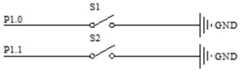
在具体实施中,输入模块106可以采用拨码开关、开关电路或其他输入装置,以便测试人员输入开始测试命令以及选择测试项目。如图3(e)所示,若输入模块106采用开关电路,则可以设置开关S1、开关S2两路开关电路,分别可以与微处理器102的P1.0引脚、P1.1引脚连接。开关S1、开关S2的开关状态可以对应四种输入信号,包括S1闭合、S2断开,S1断开、S2闭合,S1、S2全断开,S1、S2全闭合。则可以以“S1闭合、S2断开”状态对应连接器引脚间短路测试,以“S1断开、S2闭合”状态对应小板指示灯有效性测试,以“S1、S2全断开”状态对应USB接口连通性测试,以“S1、S2全闭合”状态对应按预设测试顺序执行各个测试项目。In a specific implementation, the
在上述实施例中提到,微处理器102可以通过控制报警器等装置发出报警信号、或记录故障日志或将故障信息通过通信器输出至另一设备的方式提示被测USB小板的故障信息。则如图1所示,本 申请实施例提供的USB小板的测试系统还可以包括与微处理器102连接的用于输出测试结果的输出模块107。As mentioned in the above-mentioned embodiment, the
在具体实施中,输出模块107可以包括但不限于指示灯、蜂鸣器、语音提示器。可以针对不同的测试项目的不同测试结果采用不同的指示信号。In a specific implementation, the
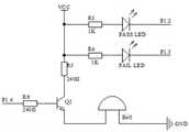
如图3(f)所示,输出模块107具体可以包括第一指示灯(PASS LED)、第二指示灯(FAIL LED)和蜂鸣器(Bell);第一指示灯(PASS LED)的阳极与第二电阻R3的第一端连接,第一指示灯(PASS LED)的阴极与微处理器102的第三输入输出引脚P1.2连接;第二指示灯(FAIL LED)的阳极与第三电阻R4的第一端连接,第二指示灯(FAIL LED)的阴极与微处理器102的第四输入输出引脚P1.3连接;第二电阻R3的第二端、第三电阻R4的第二端、第四电阻R5的第一端连接直流电源VCC5;第四电阻R5的第二端连接第二NPN三极管Q2的集电极,第二NPN三极管Q2的基极与第五电阻R6的第二端连接,第五电阻R6的第一端与微处理器102的第五输入输出引脚P1.4连接,第二NPN三极管Q2的发射极与蜂鸣器(Bell)的第一端连接,蜂鸣器(Bell)的第二端接地。As shown in FIG. 3( f ), the output module 107 may specifically include a first indicator light (PASS LED), a second indicator light (FAIL LED) and a buzzer (Bell); the anode of the first indicator light (PASS LED) Connect to the first end of the second resistor R3, the cathode of the first indicator (PASS LED) is connected to the third input and output pin P1.2 of the microprocessor 102; the anode of the second indicator (FAIL LED) is connected to the third input and output pin P1.2 of the microprocessor 102; The first end of the three resistors R4 is connected, and the cathode of the second indicator (FAIL LED) is connected to the fourth input and output pin P1.3 of the microprocessor 102; the second end of the second resistor R3, the second end of the third resistor R4 The second end and the first end of the fourth resistor R5 are connected to the DC power supply VCC5; the second end of the fourth resistor R5 is connected to the collector of the second NPN transistor Q2, the base of the second NPN transistor Q2 is connected to the first end of the fifth resistor R6 The two ends are connected, the first end of the fifth resistor R6 is connected to the fifth input and output pin P1.4 of the microprocessor 102, the emitter of the second NPN transistor Q2 is connected to the first end of the buzzer (Bell), The second end of the buzzer (Bell) is grounded.
第二NPN三极管Q2具体可以采用C945。Specifically, the second NPN transistor Q2 can be C945.
基于如图3(f)所示的输出模块107,在进行USB接口连通性测试时,微处理器102可以在确定被测USB小板的各引脚无断路情况时控制第一指示灯(PASS LED)亮起,在发现被测USB小板存在断路的引脚时控制第二指示灯(FAIL LED)亮起。在连接器引脚间短路测试时,微处理器102可以在确定被测USB小板出现引脚间短路问题时,控制蜂鸣器响起以提示故障。Based on the
上文详述了USB小板的测试系统对应的各个实施例,在此基础上,本申请还公开了与上述测试系统对应的USB小板的测试方法、测试装置、测试设备及计算机可读存储介质。 Various embodiments corresponding to the test system of the USB small board are described in detail above. On this basis, the present application also discloses the test method, test device, test equipment and computer-readable storage of the USB small board corresponding to the above test system. medium.
实施例五
应用于微处理器,微处理器与第一连接器的第一端连接,第一连接器的第二端用于连接被测USB小板的主板连接器的第一端,主板连接器的第二端与被测USB小板的USB接口的第一端连接;本申请实施例提供的USB小板的测试方法包括:Applied to the microprocessor, the microprocessor is connected to the first end of the first connector, the second end of the first connector is used to connect the first end of the mainboard connector of the USB small board under test, and the first end of the mainboard connector The two ends are connected to the first end of the USB interface of the USB small board under test; the testing method of the USB small board provided by the embodiment of the present application includes:
在第一连接器与主板连接器连接后,在被测USB小板的USB接口的第二端处于悬空状态时,通过第一连接器对主板连接器的各引脚两两为一组进行不同电平赋值,并在检测到存在实际电平与赋值电平不同的引脚时确认被测USB小板存在引脚间短路故障;After the first connector is connected to the mainboard connector, when the second end of the USB interface of the USB small board under test is in a floating state, the pins of the mainboard connector are grouped by the first connector. Level assignment, and when it is detected that there are pins with different actual levels and assigned levels, it is confirmed that there is a short circuit between pins on the USB board under test;
在第一连接器与主板连接器连接后,在被测USB小板的USB接口的第二端处于接地状态时,通过第一连接器将主板连接器的各引脚赋为高电平,并在检测到主板连接器的各引脚均根据USB接口的第二端的电平发生变化时,确认被测USB小板的USB接口有效。After the first connector is connected to the mainboard connector, when the second end of the USB interface of the USB small board under test is in a grounded state, each pin of the mainboard connector is set to a high level through the first connector, and When it is detected that each pin of the mainboard connector changes according to the level of the second end of the USB interface, confirm that the USB interface of the tested USB small board is valid.
进一步的,若被测USB小板还包括小板指示灯;小板指示灯的阳极与主板连接器的电源引脚连接,小板指示灯的阴极与主板连接器的指示灯引脚连接;测试系统还包括第二切换电路;第二切换电路的控制端与微处理器连接,第二切换电路的静触点与第一连接器的电源引脚连接,第二切换电路的第一动触点与直流电源连接,第二切换电路的第二动触点与微处理器的第一输入输出引脚连接;本申请实施例提供的USB小板的测试方法还可以包括:Further, if the USB small board under test also includes a small board indicator light; the anode of the small board indicator light is connected to the power supply pin of the main board connector, and the cathode of the small board indicator light is connected to the indicator light pin of the main board connector; test The system also includes a second switching circuit; the control end of the second switching circuit is connected to the microprocessor, the static contact of the second switching circuit is connected to the power supply pin of the first connector, and the first movable contact of the second switching circuit is connected to the DC power supply, and the second movable contact of the second switching circuit is connected to the first input and output pins of the microprocessor; the testing method for the USB small board provided by the embodiment of the present application may further include:
在第一连接器与主板连接器连接后,控制第二切换电路切换至第一动触点,通过第一连接器将主板连接器的指示灯引脚赋为低电平,以根据小板指示灯的亮灭对小板指示灯所在支路进行有效性评估。After the first connector is connected with the mainboard connector, the second switching circuit is controlled to switch to the first movable contact, and the indicator pin of the mainboard connector is set to a low level through the first connector, so as to indicate by the small board The light on and off evaluates the validity of the branch where the indicator light of the small board is located.
由于测试方法部分的实施例与测试系统部分的实施例相互对应,因此测试方法部分的实施例请参见测试系统部分的实施例的描述,这里暂不赘述。Since the embodiment of the test method part corresponds to the embodiment of the test system part, for the embodiment of the test method part, please refer to the description of the embodiment of the test system part, which will not be repeated here.
实施例六
图4为本申请实施例提供的一种USB小板的测试装置的结构示意图。FIG. 4 is a schematic structural diagram of a testing device for a USB small board according to an embodiment of the present application.
如图4所示,应用于微处理器,微处理器与第一连接器的第一端连接,第一连接器的第二端用于连接被测USB小板的主板连接器的第一端,主板连接器的第二端与被测USB小板的USB接口的第一端连接;本申请实施例提供USB小板的测试装置包括:As shown in Figure 4, when applied to a microprocessor, the microprocessor is connected to the first end of the first connector, and the second end of the first connector is used to connect to the first end of the motherboard connector of the USB small board under test , the second end of the mainboard connector is connected with the first end of the USB interface of the USB small board under test; the test device for the USB small board provided in the embodiment of the present application includes:
短路测试单元401,用于在第一连接器与主板连接器连接后,在被测USB小板的USB接口的第二端处于悬空状态时,通过第一连接器对主板连接器的各引脚两两为一组进行不同电平赋值,并在检测到存在实际电平与赋值电平不同的引脚时确认被测USB小板存在引脚间短路故障;The short-
断路测试单元402,用于在第一连接器与主板连接器连接后,在被测USB小板的USB接口的第二端处于接地状态时,通过第一连接器将主板连接器的各引脚赋为高电平,并在检测到主板连接器的各引脚均根据USB接口的第二端的电平发生变化时,确认被测USB小板的USB接口有效。The circuit
进一步的,若被测USB小板还包括小板指示灯;小板指示灯的阳极与主板连接器的电源引脚连接,小板指示灯的阴极与主板连接器的指示灯引脚连接;测试系统还包括第二切换电路;第二切换电路的控制端与微处理器连接,第二切换电路的静触点与第一连接器的电源引脚连接,第二切换电路的第一动触点与直流电源连接,第二切换电路的第二动触点与微处理器的第一输入输出引脚连接;本申请实施例提供的USB小板的测试装置还可以包括:Further, if the USB small board under test also includes a small board indicator light; the anode of the small board indicator light is connected to the power supply pin of the main board connector, and the cathode of the small board indicator light is connected to the indicator light pin of the main board connector; test The system also includes a second switching circuit; the control end of the second switching circuit is connected to the microprocessor, the static contact of the second switching circuit is connected to the power supply pin of the first connector, and the first movable contact of the second switching circuit Connected to the DC power supply, the second movable contact of the second switching circuit is connected to the first input and output pins of the microprocessor; the testing device for the USB small board provided by the embodiment of the present application may further include:
指示灯测试单元,用于在第一连接器与主板连接器连接后,控制第二切换电路切换至第一动触点,通过第一连接器将主板连接器的指示灯引脚赋为低电平,以根据小板指示灯的亮灭对小板指示灯所在支路进行有效性评估。The indicator light test unit is used to control the second switching circuit to switch to the first movable contact after the first connector is connected with the mainboard connector, and assign the indicator pin of the mainboard connector to low power through the first connector level, so as to evaluate the effectiveness of the branch where the indicator light of the small board is located according to the on/off of the indicator light of the small board.
由于测试装置部分的实施例与测试系统部分的实施例相互对应,因此测试装置部分的实施例请参见测试系统部分的实施例的描述,这里暂不赘述。Since the embodiment of the test device part corresponds to the embodiment of the test system part, for the embodiment of the test device part, please refer to the description of the embodiment of the test system part, which will not be repeated here.
实施例七
图5为本申请实施例提供的一种USB小板的测试设备的结构示意图。FIG. 5 is a schematic structural diagram of a testing device for a USB small board according to an embodiment of the present application.
如图5所示,本申请实施例提供的USB小板的测试设备包括:As shown in FIG. 5 , the test equipment for the USB small board provided by the embodiment of the present application includes:
存储器510,用于存储计算机程序511;a memory 510 for storing a computer program 511;
处理器520,用于执行计算机程序511,该计算机程序511被处理器520执行时实现如上述任意一项实施例所述USB小板的测试方法的步骤。The processor 520 is configured to execute the computer program 511. When the computer program 511 is executed by the processor 520, the steps of the method for testing a USB small board according to any one of the foregoing embodiments are implemented.
其中,处理器520可以包括一个或多个处理核心,比如3核心处理器、8核心处理器等。处理器520可以采用数字信号处理DSP(Digital Signal Processing)、现场可编程门阵列FPGA(Field-Programmable Gate Array)、可编程逻辑阵列PLA(Programmable LogicArray)中的至少一种硬件形式来实现。处理器520也可以包括主处理器和协处理器,主处理器是用于对在唤醒状态下的数据进行处理的处理器,也称中央处理器CPU(CentralProcessing Unit);协处理器是用于对在待机状态下的数据进行处理的低功耗处理器。在一些实施例中,处理器520可以集成有图像处理器GPU(Graphics Processing Unit),GPU用于负责显示屏所需要显示的内容的渲染和绘制。一些实施例中,处理器520还可以包括人工智能AI(Artificial Intelligence)处理器,该AI处理器用于处理有关机器学习的计算操作。The processor 520 may include one or more processing cores, such as a 3-core processor, an 8-core processor, and the like. The processor 520 may be implemented in at least one hardware form of a digital signal processing DSP (Digital Signal Processing), a Field-Programmable Gate Array (FPGA), and a Programmable Logic Array (PLA). The processor 520 may also include a main processor and a co-processor. The main processor is a processor used to process data in the wake-up state, also called a central processing unit (CPU); the co-processor is used for processing data in the wake-up state. A low-power processor that processes data in a standby state. In some embodiments, the processor 520 may be integrated with a graphics processing unit (GPU), and the GPU is used for rendering and drawing the content that needs to be displayed on the display screen. In some embodiments, the processor 520 may further include an artificial intelligence (Artificial Intelligence) processor for processing computing operations related to machine learning.
存储器510可以包括一个或多个计算机可读存储介质,该计算机可读存储介质可以是非暂态的。存储器510还可包括高速随机存取存储器,以及非易失性存储器,比如一个或多个磁盘存储设备、闪存存储设备。本实施例中,存储器510至少用于存储以下计算机程序511,其中,该计算机程序511被处理器520加载并执行之后,能够实现前述任一实施例公开的USB小板的测试方法中的相关步骤。另外,存储器510所存储的资源还可以包括操作系统512和数据513等,存储方式可以是短暂存储或者永久存储。其中,操作系统512可以为Windows。数据513可以包括但不限于上述方法所涉及到的数据。Memory 510 may include one or more computer-readable storage media, which may be non-transitory. Memory 510 may also include high-speed random access memory, as well as non-volatile memory, such as one or more disk storage devices, flash storage devices. In this embodiment, the memory 510 is at least used to store the following computer program 511, where, after the computer program 511 is loaded and executed by the processor 520, it can implement the relevant steps in the USB small board testing method disclosed in any of the foregoing embodiments . In addition, the resources stored in the memory 510 may also include an operating system 512, data 513, etc., and the storage mode may be short-term storage or permanent storage. The operating system 512 may be Windows. The data 513 may include, but is not limited to, the data involved in the above methods.
在一些实施例中,USB小板的测试设备还可包括有显示屏530、电源540、通信接口550、输入输出接口560、传感器570以及通信总线580。In some embodiments, the testing equipment for the USB small board may further include a
本领域技术人员可以理解,图5中示出的结构并不构成对USB小板的测试设备的限定,可以包括比图示更多或更少的组件。Those skilled in the art can understand that the structure shown in FIG. 5 does not constitute a limitation on the testing equipment of the USB small board, and may include more or less components than those shown in the drawings.
本申请实施例提供的USB小板的测试设备,包括存储器和处理器,处理器在执行存储器存储的程序时,能够实现如上所述的USB小板的测试方法,效果同上。The testing device for a USB small board provided by the embodiment of the present application includes a memory and a processor. When the processor executes a program stored in the memory, the processor can implement the above-mentioned testing method for the USB small board, and the effect is the same as above.
实施例八
需要说明的是,以上所描述的装置、设备实施例仅仅是示意性的,例如,模块的划分,仅仅为一种逻辑功能划分,实际实现时可以有另外的划分方式,例如多个模块或组件可以结合或者可以集成到另一个系统,或一些特征可以忽略,或不执行。另一点,所显示或讨论的相互之间的耦合或直接耦合或通信连接可以是通过一些接口,装置或模块的间接耦合或通信连接,可以是电性,机械或其它的形式。作为分离部件说明的模块可以是或者也可以不是物理上分开的,作为模块显示的部件可以是或者也可以不是物理模块,即可以位于一个地方,或者也可以分布到多个网络模块上。可以根据实际的需要选择其中的部分或者全部模块来实现本实施例方案的目的。It should be noted that the above-described apparatus and device embodiments are only illustrative. For example, the division of modules is only a logical function division. In actual implementation, there may be other division methods, such as multiple modules or components. May be combined or may be integrated into another system, or some features may be omitted, or not implemented. On the other hand, the shown or discussed mutual coupling or direct coupling or communication connection may be through some interfaces, indirect coupling or communication connection of devices or modules, and may be in electrical, mechanical or other forms. Modules described as separate components may or may not be physically separated, and components shown as modules may or may not be physical modules, that is, they may be located in one place, or may be distributed to multiple network modules. Some or all of the modules may be selected according to actual needs to achieve the purpose of the solution in this embodiment.
另外,在本申请各个实施例中的各功能模块可以集成在一个处理模块中,也可以是各个模块单独物理存在,也可以两个或两个以上模块集成在一个模块中。上述集成的模块既可以采用硬件的形式实现,也可以采用软件功能模块的形式实现。In addition, each functional module in each embodiment of the present application may be integrated into one processing module, or each module may exist physically alone, or two or more modules may be integrated into one module. The above-mentioned integrated modules can be implemented in the form of hardware, and can also be implemented in the form of software function modules.
集成的模块如果以软件功能模块的形式实现并作为独立的产品销售或使用时,可以存储在一个计算机可读存储介质中。基于这样的理解,本申请的技术方案本质上或者说对现有技术做出贡献的部分或者该技术方案的全部或部分可以以软件产品的形式体现出来,该计算机软件产品存储在一个存储介质中,执行本申请各个实施例所述方法的全部或部分步骤。The integrated modules, if implemented in the form of software functional modules and sold or used as independent products, can be stored in a computer-readable storage medium. Based on this understanding, the technical solutions of the present application can be embodied in the form of software products in essence, or the parts that contribute to the prior art, or all or part of the technical solutions, and the computer software products are stored in a storage medium , execute all or part of the steps of the methods described in the various embodiments of the present application.
为此,本申请实施例还提供一种计算机可读存储介质,该计算机可读存储介质上存储有计算机程序,计算机程序被处理器执行时实现如USB小板的测试方法的步骤。To this end, an embodiment of the present application further provides a computer-readable storage medium, where a computer program is stored on the computer-readable storage medium, and when the computer program is executed by a processor, the steps of the test method for a USB small board are implemented.
该计算机可读存储介质可以包括:U盘、移动硬盘、只读存储器ROM(Read-OnlyMemory)、随机存取存储器RAM(Random Access Memory)、磁碟或者光盘等各种可以存储程序代码的介质。The computer-readable storage medium may include: a U disk, a removable hard disk, a read-only memory (ROM), a random access memory (RAM), a magnetic disk or an optical disk and other mediums that can store program codes.
本实施例中提供的计算机可读存储介质所包含的计算机程序能够在被处理器执行时实现如上所述的USB小板的测试方法的步骤,效果同上。The computer program included in the computer-readable storage medium provided in this embodiment can, when executed by the processor, implement the steps of the USB small board testing method described above, and the effects are the same as above.
以上对本申请所提供的一种USB小板的测试系统、测试方法、测试装置、测试设备及计算机可读存储介质进行了详细介绍。说明书中各个实施例采用递进的方式描述,每个实施例重点说明的都是与其他实施例的不同之处,各个实施例之间相同相似部分互相参见即可。对于实施例公开的方法、装置、设备及计算机可读存储介质而言,由于其与实施例公开的系统相对应,所以描述的比较简单,相关之处参见系统部分说明即可。应当指出,对于本技术领域的普通技术人员来说,在不脱离本申请原理的前提下,还可以对本申请进行若干改进和修饰,这些改进和修饰也落入本申请权利要求的保护范围内。The test system, test method, test device, test equipment and computer-readable storage medium of a USB small board provided by the present application have been described above in detail. The various embodiments in the specification are described in a progressive manner, and each embodiment focuses on the differences from other embodiments, and the same and similar parts between the various embodiments can be referred to each other. For the methods, apparatuses, devices and computer-readable storage media disclosed in the embodiments, since they correspond to the systems disclosed in the embodiments, the descriptions are relatively simple, and the relevant parts can be referred to the description of the system. It should be pointed out that for those of ordinary skill in the art, without departing from the principles of the present application, several improvements and modifications can also be made to the present application, and these improvements and modifications also fall within the protection scope of the claims of the present application.
还需要说明的是,在本说明书中,诸如第一和第二等之类的关系术语仅仅用来将一个实体或者操作与另一个实体或操作区分开来,而不一定要求或者暗示这些实体或操作之间存在任何这种实际的关系或者顺序。而且,术语“包括”、“包含”或者其任何其他变体意在涵盖非排他性的包含,从而使得包括一系列要素的过程、方法、物品或者设备不仅包括那些要素,而且还包括没有明确列出的其他要素,或者是还包括为这种过程、方法、物品或者设备所固有的要素。在没有更多限制的情况下,由语句“包括一个……”限定的要素,并不排除在包括所述要素的过程、方法、物品或者设备中还存在另外的相同要素。It should also be noted that, in this specification, relational terms such as first and second, etc. are only used to distinguish one entity or operation from another entity or operation, and do not necessarily require or imply these entities or operations. There is no such actual relationship or sequence between operations. Moreover, the terms "comprising", "comprising" or any other variation thereof are intended to encompass non-exclusive inclusion such that a process, method, article or device comprising a list of elements includes not only those elements, but also includes not explicitly listed or other elements inherent to such a process, method, article or apparatus. Without further limitation, an element qualified by the phrase "comprising a..." does not preclude the presence of additional identical elements in a process, method, article or apparatus that includes the element.
Claims (9)
Priority Applications (1)
| Application Number | Priority Date | Filing Date | Title |
|---|---|---|---|
| CN202210051770.3ACN114064373B (en) | 2022-01-18 | 2022-01-18 | Test system, test method, test device and test equipment for USB platelet |
Applications Claiming Priority (1)
| Application Number | Priority Date | Filing Date | Title |
|---|---|---|---|
| CN202210051770.3ACN114064373B (en) | 2022-01-18 | 2022-01-18 | Test system, test method, test device and test equipment for USB platelet |
Publications (2)
| Publication Number | Publication Date |
|---|---|
| CN114064373A CN114064373A (en) | 2022-02-18 |
| CN114064373Btrue CN114064373B (en) | 2022-04-22 |
Family
ID=80231262
Family Applications (1)
| Application Number | Title | Priority Date | Filing Date |
|---|---|---|---|
| CN202210051770.3AActiveCN114064373B (en) | 2022-01-18 | 2022-01-18 | Test system, test method, test device and test equipment for USB platelet |
Country Status (1)
| Country | Link |
|---|---|
| CN (1) | CN114064373B (en) |
Families Citing this family (1)
| Publication number | Priority date | Publication date | Assignee | Title |
|---|---|---|---|---|
| CN117110830A (en)* | 2023-02-08 | 2023-11-24 | 荣耀终端有限公司 | An electrical detection device and electrical detection equipment |
Citations (6)
| Publication number | Priority date | Publication date | Assignee | Title |
|---|---|---|---|---|
| CN105630724A (en)* | 2016-01-27 | 2016-06-01 | 深圳慧能泰半导体科技有限公司 | USB Type-C system control circuit |
| CN109254889A (en)* | 2018-10-22 | 2019-01-22 | 河南思维轨道交通技术研究院有限公司 | A kind of localization method carrying out CPU pin short trouble using embedded software |
| CN110261717A (en)* | 2019-07-15 | 2019-09-20 | 立讯精密工业(滁州)有限公司 | A kind of connector assembly test circuit and its test method |
| CN111274177A (en)* | 2018-12-19 | 2020-06-12 | 深圳市鸿合创新信息技术有限责任公司 | OPS computer plug protection device and electronic equipment with same |
| CN111949457A (en)* | 2020-07-27 | 2020-11-17 | 中国长城科技集团股份有限公司 | Server fault chip detection method and device |
| CN113567832A (en)* | 2021-07-08 | 2021-10-29 | 北京中电华大电子设计有限责任公司 | Testing device for IO connectivity of circuit board |
Family Cites Families (3)
| Publication number | Priority date | Publication date | Assignee | Title |
|---|---|---|---|---|
| CN108804261B (en)* | 2017-05-05 | 2023-05-19 | 中兴通讯股份有限公司 | Connector testing method and device |
| CN208141371U (en)* | 2018-05-18 | 2018-11-23 | 郑州云海信息技术有限公司 | A kind of multi-functional UART debugging board |
| CN213482386U (en)* | 2020-10-23 | 2021-06-18 | 南京创维平面显示科技有限公司 | USB adapter plate test circuit and test fixture |
- 2022
- 2022-01-18CNCN202210051770.3Apatent/CN114064373B/enactiveActive
Patent Citations (6)
| Publication number | Priority date | Publication date | Assignee | Title |
|---|---|---|---|---|
| CN105630724A (en)* | 2016-01-27 | 2016-06-01 | 深圳慧能泰半导体科技有限公司 | USB Type-C system control circuit |
| CN109254889A (en)* | 2018-10-22 | 2019-01-22 | 河南思维轨道交通技术研究院有限公司 | A kind of localization method carrying out CPU pin short trouble using embedded software |
| CN111274177A (en)* | 2018-12-19 | 2020-06-12 | 深圳市鸿合创新信息技术有限责任公司 | OPS computer plug protection device and electronic equipment with same |
| CN110261717A (en)* | 2019-07-15 | 2019-09-20 | 立讯精密工业(滁州)有限公司 | A kind of connector assembly test circuit and its test method |
| CN111949457A (en)* | 2020-07-27 | 2020-11-17 | 中国长城科技集团股份有限公司 | Server fault chip detection method and device |
| CN113567832A (en)* | 2021-07-08 | 2021-10-29 | 北京中电华大电子设计有限责任公司 | Testing device for IO connectivity of circuit board |
Also Published As
| Publication number | Publication date |
|---|---|
| CN114064373A (en) | 2022-02-18 |
Similar Documents
| Publication | Publication Date | Title |
|---|---|---|
| CN115210589B (en) | Chip testing device and testing method | |
| CN103149526B (en) | PCBA board test macro and method | |
| US7987389B2 (en) | System and method for testing sleep and wake functions of computer | |
| CN112527582A (en) | Detection method, detection device, detection equipment and storage medium of server cable | |
| CN216748731U (en) | Detection circuit, interface link tooling plate and detection system | |
| CN110489287B (en) | Method, system and storage medium for testing hot plug through Ipomitool | |
| CN100377102C (en) | Motherboard function test board | |
| CN103631688A (en) | Method and system for testing interface signal | |
| CN111831495B (en) | Production automation testing method and system | |
| CN109298266A (en) | Test system, test method, test apparatus, and storage medium | |
| CN101408857B (en) | SAS interface test device | |
| WO2014082275A1 (en) | Method and apparatus for detecting cable connection condition | |
| CN114064373B (en) | Test system, test method, test device and test equipment for USB platelet | |
| CN217787754U (en) | Automated Test Devices and Systems | |
| CN113985321B (en) | Cable connection performance testing device and method with intelligent self-learning capability | |
| CN115757219A (en) | A hard disk control device, method, equipment, readable storage medium and server | |
| CN110888053A (en) | Relay detection device, detection system and detection method | |
| CN114325489A (en) | High-speed cable test system, test method, test device and test equipment | |
| CN113204456A (en) | Test method, tool, device and equipment for VPP interface of server | |
| CN1797357A (en) | Circuit board for testing function of main board | |
| CN112596983A (en) | A monitoring method for a connector in a server | |
| CN111722149A (en) | A cable detection device, method, system and computer-readable storage medium | |
| CN114996159A (en) | NVME SSD interface fault signal injection method, device, equipment and readable medium | |
| CN116684343A (en) | Automatic test method, device, system, equipment and medium for switch | |
| CN115718473A (en) | Controller chip testing arrangement |
Legal Events
| Date | Code | Title | Description |
|---|---|---|---|
| PB01 | Publication | ||
| PB01 | Publication | ||
| SE01 | Entry into force of request for substantive examination | ||
| SE01 | Entry into force of request for substantive examination | ||
| GR01 | Patent grant | ||
| GR01 | Patent grant | ||
| CP03 | Change of name, title or address | Address after:Building 9, No.1, guanpu Road, Guoxiang street, Wuzhong Economic Development Zone, Wuzhong District, Suzhou City, Jiangsu Province Patentee after:Suzhou Yuannao Intelligent Technology Co.,Ltd. Country or region after:China Address before:Building 9, No.1, guanpu Road, Guoxiang street, Wuzhong Economic Development Zone, Wuzhong District, Suzhou City, Jiangsu Province Patentee before:SUZHOU LANGCHAO INTELLIGENT TECHNOLOGY Co.,Ltd. Country or region before:China |