CN114053541B - Intranasal intubate protector - Google Patents
Intranasal intubate protectorDownload PDFInfo
- Publication number
- CN114053541B CN114053541BCN202111330121.9ACN202111330121ACN114053541BCN 114053541 BCN114053541 BCN 114053541BCN 202111330121 ACN202111330121 ACN 202111330121ACN 114053541 BCN114053541 BCN 114053541B
- Authority
- CN
- China
- Prior art keywords
- arc
- arch
- column
- plate
- arc arch
- Prior art date
- Legal status (The legal status is an assumption and is not a legal conclusion. Google has not performed a legal analysis and makes no representation as to the accuracy of the status listed.)
- Active
Links
- 230000001012protectorEffects0.000title1
- 238000002627tracheal intubationMethods0.000claimsabstractdescription50
- 210000003928nasal cavityAnatomy0.000claimsabstractdescription31
- 230000001681protective effectEffects0.000claimsabstractdescription9
- 210000004072lungAnatomy0.000abstractdescription9
- 210000002050maxillaAnatomy0.000abstractdescription4
- 238000002271resectionMethods0.000description5
- 238000010586diagramMethods0.000description4
- 238000000034methodMethods0.000description4
- 230000000638stimulationEffects0.000description3
- FGRBYDKOBBBPOI-UHFFFAOYSA-N10,10-dioxo-2-[4-(N-phenylanilino)phenyl]thioxanthen-9-oneChemical compoundO=C1c2ccccc2S(=O)(=O)c2ccc(cc12)-c1ccc(cc1)N(c1ccccc1)c1ccccc1FGRBYDKOBBBPOI-UHFFFAOYSA-N0.000description2
- 240000007643Phytolacca americanaSpecies0.000description2
- 230000029058respiratory gaseous exchangeEffects0.000description2
- 206010028980NeoplasmDiseases0.000description1
- 230000009286beneficial effectEffects0.000description1
- 238000002695general anesthesiaMethods0.000description1
- 210000001331noseAnatomy0.000description1
- 238000001356surgical procedureMethods0.000description1
- 230000009466transformationEffects0.000description1
Images


Classifications
- A—HUMAN NECESSITIES
- A61—MEDICAL OR VETERINARY SCIENCE; HYGIENE
- A61M—DEVICES FOR INTRODUCING MEDIA INTO, OR ONTO, THE BODY; DEVICES FOR TRANSDUCING BODY MEDIA OR FOR TAKING MEDIA FROM THE BODY; DEVICES FOR PRODUCING OR ENDING SLEEP OR STUPOR
- A61M16/00—Devices for influencing the respiratory system of patients by gas treatment, e.g. ventilators; Tracheal tubes
- A61M16/04—Tracheal tubes
- A61M16/0488—Mouthpieces; Means for guiding, securing or introducing the tubes
- A—HUMAN NECESSITIES
- A61—MEDICAL OR VETERINARY SCIENCE; HYGIENE
- A61M—DEVICES FOR INTRODUCING MEDIA INTO, OR ONTO, THE BODY; DEVICES FOR TRANSDUCING BODY MEDIA OR FOR TAKING MEDIA FROM THE BODY; DEVICES FOR PRODUCING OR ENDING SLEEP OR STUPOR
- A61M25/00—Catheters; Hollow probes
- A61M25/0021—Catheters; Hollow probes characterised by the form of the tubing
- A—HUMAN NECESSITIES
- A61—MEDICAL OR VETERINARY SCIENCE; HYGIENE
- A61M—DEVICES FOR INTRODUCING MEDIA INTO, OR ONTO, THE BODY; DEVICES FOR TRANSDUCING BODY MEDIA OR FOR TAKING MEDIA FROM THE BODY; DEVICES FOR PRODUCING OR ENDING SLEEP OR STUPOR
- A61M25/00—Catheters; Hollow probes
- A61M2025/0098—Catheters; Hollow probes having a strain relief at the proximal end, e.g. sleeve
- A—HUMAN NECESSITIES
- A61—MEDICAL OR VETERINARY SCIENCE; HYGIENE
- A61M—DEVICES FOR INTRODUCING MEDIA INTO, OR ONTO, THE BODY; DEVICES FOR TRANSDUCING BODY MEDIA OR FOR TAKING MEDIA FROM THE BODY; DEVICES FOR PRODUCING OR ENDING SLEEP OR STUPOR
- A61M25/00—Catheters; Hollow probes
- A61M25/01—Introducing, guiding, advancing, emplacing or holding catheters
- A61M25/02—Holding devices, e.g. on the body
- A61M2025/0213—Holding devices, e.g. on the body where the catheter is attached by means specifically adapted to a part of the human body
- A61M2025/0226—Holding devices, e.g. on the body where the catheter is attached by means specifically adapted to a part of the human body specifically adapted for the nose
Landscapes
- Health & Medical Sciences (AREA)
- Pulmonology (AREA)
- Life Sciences & Earth Sciences (AREA)
- Hematology (AREA)
- General Health & Medical Sciences (AREA)
- Anesthesiology (AREA)
- Biomedical Technology (AREA)
- Heart & Thoracic Surgery (AREA)
- Veterinary Medicine (AREA)
- Animal Behavior & Ethology (AREA)
- Engineering & Computer Science (AREA)
- Public Health (AREA)
- Biophysics (AREA)
- Otolaryngology (AREA)
- Emergency Medicine (AREA)
- Orthopedics, Nursing, And Contraception (AREA)
- Surgical Instruments (AREA)
Abstract
Description
Translated fromChinese技术领域technical field
本发明属于医疗用品领域,具体地说涉及经鼻插管防护装置。The invention belongs to the field of medical supplies, in particular to a protective device for nasal intubation.
背景技术Background technique
目前患者全身麻醉后,患者呼吸的方式主要是“经鼻插管”和“经口插管”进行辅助呼吸,呼吸机通过插管向患者肺部输气。再行口腔颌面外科手术的过程中,经口插管会导致手术的视野受限,绝大多数情况下,都会选择经鼻插管。但是再行上颌骨肿瘤的切除时,我们会切除部分上颌骨,甚至全切以及扩大切除,常常会切过腭中缝到对侧。At present, after the patient is under general anesthesia, the patient's breathing method is mainly "nasal intubation" and "oral intubation" for assisted breathing, and the ventilator delivers air to the patient's lungs through the intubation. In the process of oral and maxillofacial surgery, oral intubation will result in limited surgical field of view, and in most cases, nasal intubation will be chosen. However, when performing maxillary tumor resection, we will resect part of the maxilla, or even complete resection and extended resection, and often cut through the midpalatal suture to the opposite side.
在使用来福锯或者电钻磨头行上颌骨切除时,常常会损伤到经鼻插入的输气插管,机械刺激产生的热量甚至可能会通过插管输气传递至肺部,导致肺部灼伤。现临床中无保护经鼻插管的装置,外科医师很大程度上还是通过经验来判断,这样也会增加损伤插管的风险。另外,不同患者鼻腔孔径的大小存在差异,如何有效保护插管仍需解决。When using a rifle saw or an electric drill for maxillary resection, the air intubation inserted through the nose is often damaged, and the heat generated by mechanical stimulation may even be transmitted to the lungs through the intubation air, resulting in lung burns . There are currently unprotected nasal intubation devices in clinical practice, and surgeons largely rely on experience to judge, which will also increase the risk of intubation damage. In addition, there are differences in the size of the nasal cavity in different patients, and how to effectively protect the intubation still needs to be solved.
发明内容Contents of the invention
本发明的目的是针对上述不足之处提供经鼻插管防护装置,拟解决现临床中无保护经鼻插管的装置,外科医师很大程度上还是通过经验来判断,这样也会增加损伤插管的风险;另外,不同患者鼻腔孔径的大小存在差异,如何有效保护插管仍需解决等问题。为实现上述目的,本发明提供如下技术方案:The purpose of the present invention is to provide a protective device for nasal intubation in view of the above disadvantages. It is intended to solve the problem of unprotected nasal intubation devices in clinical practice. Surgeons still judge by experience to a large extent, which will also increase the damage to the intubation device. In addition, there are differences in the size of the nasal cavity in different patients, and how to effectively protect the intubation still needs to be solved. To achieve the above object, the present invention provides the following technical solutions:
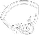
经鼻插管防护装置,包括操作部和圆弧拱板5;所述操作部和圆弧拱板5连接,且操作部位于圆弧拱板5一端;所述圆弧拱板5用于插在插管和鼻腔的间隙中,且圆弧拱板5围在鼻腔内的插管外周。由上述结构可知,鼻腔内插入输气的插管后,插管和鼻腔内壁存在间隙,当使用来福锯或者电钻磨头行上颌骨切除时,将圆弧拱板5从鼻孔插入插管和鼻腔的间隙中,圆弧拱板5由于是弧形结构,可以部分包围在鼻腔内的插管外周,圆弧拱板5和插管形成配合,也更好配合插管和鼻腔的间隙,圆弧拱板5挡在插管靠近上颌骨一侧,这样外科医师不必担心操作失误使插管受损,圆弧拱板5起到抵挡外部工具破坏插管和保护插管的作用。插管受到防护后,避免机械刺激产生的热量通过插管输气传递至肺部,保证肺部安全。操作部和圆弧拱板5连接,操作部位于圆弧拱板5一端,即操作部位于鼻孔外,外科医生通过操作部可以调整鼻腔内圆弧拱板5的位置,使圆弧拱板5更好适配插管和鼻腔的间隙,有效保护插管。The protective device for nasal intubation includes an operating portion and an
进一步的,所述操作部包括把手1、弧形管2和两个螺栓3;所述把手1和弧形管2固定;所述弧形管2外壁上设有沿着弧形管2延伸的弧形开口4;所述弧形管2两端通过螺纹连接有螺栓3;所述圆弧拱板5一端设有弧形柱6;所述弧形柱6配合在弧形管2内,且圆弧拱板5从弧形开口4穿出。由上述结构可知,弧形管2、弧形开口4、弧形柱6、圆弧拱板5保持同一轴心,这样弧形柱6可以从弧形管2端部旋转塞到弧形管2内,且圆弧拱板5沿着弧形开口4转动。两个螺栓3的杆部设有外螺纹,弧形管2两端内壁设有内螺纹,弧形管2两端通过螺纹连接有螺栓3,两个螺栓3对弧形柱6两端进行限位,避免弧形柱6带着圆弧拱板5随意转动。该可拆卸结构可以方便更换不同长度的圆弧拱板5,以适配不同患者的鼻腔深度。外科医生可以通过把手1调整弧形管2的位置,从而调整圆弧拱板5和弧形柱6的位置。弧形开口4完全延伸至弧形管2的两端。Further, the operating part includes a
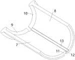
进一步的,所述圆弧拱板5包括左圆弧拱板7和右圆弧拱板8;所述弧形柱6包括位于左圆弧拱板7一端的左弧形柱9和位于右圆弧拱板8一端的右弧形柱10;所述左弧形柱9和右弧形柱10断开设置;所述左圆弧拱板7靠近右圆弧拱板8侧设有上搭接板11;所述右圆弧拱板8靠近左圆弧拱板7侧设有下搭接板12;所述上搭接板11搭接在下搭接板12上侧;所述下搭接板12上侧设有弹性橡胶条13;所述上搭接板11抵靠弹性橡胶条13。由上述结构可知,圆弧拱板5是由左圆弧拱板7和右圆弧拱板8拼接而成,当圆弧拱板5整体宽度需要调大一点时,两个螺栓3向外旋出一点,这样左弧形柱9和右弧形柱10所在空间增加,由于上搭接板11抵靠弹性橡胶条13,弹性橡胶条13位于下搭接板12上侧,弹性橡胶条13的弹力使左圆弧拱板7和右圆弧拱板8有排开的趋势,从而左弧形柱9和右弧形柱10有排开的趋势,左弧形柱9一端继续顶到一个螺栓3,右弧形柱10一端继续顶到另一个螺栓3,圆弧拱板5整体宽度增加。当圆弧拱板5整体宽度需要调小一点时,两个螺栓3向弧形管2端内旋入一点,这样左弧形柱9和右弧形柱10所在空间减小,由于上搭接板11抵靠弹性橡胶条13,弹性橡胶条13位于下搭接板12上侧,左圆弧拱板7和右圆弧拱板8靠近使弹性橡胶条13进一步压缩,从而左弧形柱9和右弧形柱10仍有排开的趋势,左弧形柱9一端继续顶到一个螺栓3,右弧形柱10一端继续顶到另一个螺栓3,圆弧拱板5整体宽度减小。圆弧拱板5整体宽度大小可调,使圆弧拱板5可以适配不同患者鼻腔孔径。Further, the
进一步的,两个螺栓3和左弧形柱9、右弧形柱10一一对应;所述螺栓3底部设有圆台14;所述左弧形柱9对应的螺栓3的圆台14小端抵靠在左弧形柱9的一端;所述右弧形柱10对应的螺栓3的圆台14小端抵靠在右弧形柱10的一端。由上述结构可知,由于弧形管2是弧形,所以为了保证螺栓3始终能够顶到左弧形柱9、右弧形柱10一端,采用在螺栓3底部设有圆台14,圆台14小于螺纹口径,所以螺栓3旋入旋出时,圆台14均可以接触到左弧形柱9、右弧形柱10一端。Further, the two
进一步的,所述弧形管2为半圆弧形。由上述结构可知,弧形管2为半圆弧形,圆弧拱板5也可以最大占据180度转角。Further, the
进一步的,左圆弧拱板7和右圆弧拱板8所有边缘设有倒圆角。由上述结构可知,倒圆角避免左圆弧拱板7和右圆弧拱板8具有锋利处,图中虽未示意出,实际加工均需要进行倒圆角,保证装置使用的安全,不会戳伤鼻腔。Further, all edges of the
本发明的有益效果是:The beneficial effects of the present invention are:
本发明公开了经鼻插管防护装置,包括操作部和圆弧拱板;所述操作部和圆弧拱板连接,且操作部位于圆弧拱板一端;所述圆弧拱板用于插在插管和鼻腔的间隙中,且圆弧拱板围在鼻腔内的插管外周。本发明的经鼻插管防护装置,在上颌骨切除时,可以保护插管,避免插管损伤,以及防止热传递至肺部。圆弧拱板尺寸可调节,适应不同患者鼻腔孔径的大小,有效保护插管。The invention discloses a protection device for nasal intubation, which comprises an operating part and an arc arch; the operating part is connected to the arc arch, and the operating part is located at one end of the arc arch; It is in the gap between the cannula and the nasal cavity, and the arc arch surrounds the outer periphery of the cannula in the nasal cavity. The nasal intubation protection device of the present invention can protect the intubation tube, avoid intubation damage, and prevent heat transfer to the lungs during maxillary resection. The size of the arc arch plate can be adjusted to adapt to the size of the nasal cavity of different patients and effectively protect the intubation tube.
附图说明Description of drawings
图1是本发明整体三维结构示意图;Fig. 1 is a schematic diagram of the overall three-dimensional structure of the present invention;
图2是本发明整体另一个视角三维结构示意图;Fig. 2 is a schematic diagram of a three-dimensional structure from another perspective of the whole of the present invention;
图3是本发明带弧形柱的圆弧拱板三维结构示意图;Fig. 3 is the schematic diagram of the three-dimensional structure of the arc arch plate with the arc column of the present invention;
图4是本发明带弧形柱的圆弧拱板另一个视角三维结构示意图;Fig. 4 is a three-dimensional structure schematic diagram of another viewing angle of the arc arch plate with arc columns of the present invention;
附图中:1-把手、2-弧形管、3-螺栓、4-弧形开口、5-圆弧拱板、6-弧形柱、7-左圆弧拱板、8-右圆弧拱板、9-左弧形柱、10-右弧形柱、11-上搭接板、12-下搭接板、13-弹性橡胶条、14-圆台。In the drawings: 1-handle, 2-arc tube, 3-bolt, 4-arc opening, 5-arc arch, 6-arc column, 7-left arc arch, 8-right arc Arch plate, 9-left arc column, 10-right arc column, 11-upper lap plate, 12-bottom lap plate, 13-elastic rubber strip, 14-round platform.
具体实施方式Detailed ways
下面结合附图与具体实施方式,对本发明进一步详细说明,但是本发明不局限于以下实施例。The present invention will be described in further detail below in conjunction with the accompanying drawings and specific embodiments, but the present invention is not limited to the following examples.
实施例一:Embodiment one:
见附图1~4。经鼻插管防护装置,包括操作部和圆弧拱板5;所述操作部和圆弧拱板5连接,且操作部位于圆弧拱板5一端;所述圆弧拱板5用于插在插管和鼻腔的间隙中,且圆弧拱板5围在鼻腔内的插管外周。由上述结构可知,鼻腔内插入输气的插管后,插管和鼻腔内壁存在间隙,当使用来福锯或者电钻磨头行上颌骨切除时,将圆弧拱板5从鼻孔插入插管和鼻腔的间隙中,圆弧拱板5由于是弧形结构,可以部分包围在鼻腔内的插管外周,圆弧拱板5和插管形成配合,也更好配合插管和鼻腔的间隙,圆弧拱板5挡在插管靠近上颌骨一侧,这样外科医师不必担心操作失误使插管受损,圆弧拱板5起到抵挡外部工具破坏插管和保护插管的作用。插管受到防护后,避免机械刺激产生的热量通过插管输气传递至肺部,保证肺部安全。操作部和圆弧拱板5连接,操作部位于圆弧拱板5一端,即操作部位于鼻孔外,外科医生通过操作部可以调整鼻腔内圆弧拱板5的位置,使圆弧拱板5更好适配插管和鼻腔的间隙,有效保护插管。See attached drawings 1-4. The protective device for nasal intubation includes an operating portion and an
实施例二:Embodiment two:
见附图1~4。在实施例一的基础上,所述操作部包括把手1、弧形管2和两个螺栓3;所述把手1和弧形管2固定;所述弧形管2外壁上设有沿着弧形管2延伸的弧形开口4;所述弧形管2两端通过螺纹连接有螺栓3;所述圆弧拱板5一端设有弧形柱6;所述弧形柱6配合在弧形管2内,且圆弧拱板5从弧形开口4穿出。由上述结构可知,弧形管2、弧形开口4、弧形柱6、圆弧拱板5保持同一轴心,这样弧形柱6可以从弧形管2端部旋转塞到弧形管2内,且圆弧拱板5沿着弧形开口4转动。两个螺栓3的杆部设有外螺纹,弧形管2两端内壁设有内螺纹,弧形管2两端通过螺纹连接有螺栓3,两个螺栓3对弧形柱6两端进行限位,避免弧形柱6带着圆弧拱板5随意转动。该可拆卸结构可以方便更换不同长度的圆弧拱板5,以适配不同患者的鼻腔深度。外科医生可以通过把手1调整弧形管2的位置,从而调整圆弧拱板5和弧形柱6的位置。弧形开口4完全延伸至弧形管2的两端。See attached drawings 1-4. On the basis of
实施例三:Embodiment three:
见附图1~4。在实施例二的基础上,所述圆弧拱板5包括左圆弧拱板7和右圆弧拱板8;所述弧形柱6包括位于左圆弧拱板7一端的左弧形柱9和位于右圆弧拱板8一端的右弧形柱10;所述左弧形柱9和右弧形柱10断开设置;所述左圆弧拱板7靠近右圆弧拱板8侧设有上搭接板11;所述右圆弧拱板8靠近左圆弧拱板7侧设有下搭接板12;所述上搭接板11搭接在下搭接板12上侧;所述下搭接板12上侧设有弹性橡胶条13;所述上搭接板11抵靠弹性橡胶条13。由上述结构可知,圆弧拱板5是由左圆弧拱板7和右圆弧拱板8拼接而成,当圆弧拱板5整体宽度需要调大一点时,两个螺栓3向外旋出一点,这样左弧形柱9和右弧形柱10所在空间增加,由于上搭接板11抵靠弹性橡胶条13,弹性橡胶条13位于下搭接板12上侧,弹性橡胶条13的弹力使左圆弧拱板7和右圆弧拱板8有排开的趋势,从而左弧形柱9和右弧形柱10有排开的趋势,左弧形柱9一端继续顶到一个螺栓3,右弧形柱10一端继续顶到另一个螺栓3,圆弧拱板5整体宽度增加。当圆弧拱板5整体宽度需要调小一点时,两个螺栓3向弧形管2端内旋入一点,这样左弧形柱9和右弧形柱10所在空间减小,由于上搭接板11抵靠弹性橡胶条13,弹性橡胶条13位于下搭接板12上侧,左圆弧拱板7和右圆弧拱板8靠近使弹性橡胶条13进一步压缩,从而左弧形柱9和右弧形柱10仍有排开的趋势,左弧形柱9一端继续顶到一个螺栓3,右弧形柱10一端继续顶到另一个螺栓3,圆弧拱板5整体宽度减小。圆弧拱板5整体宽度大小可调,使圆弧拱板5可以适配不同患者鼻腔孔径。See attached drawings 1-4. On the basis of the second embodiment, the
两个螺栓3和左弧形柱9、右弧形柱10一一对应;所述螺栓3底部设有圆台14;所述左弧形柱9对应的螺栓3的圆台14小端抵靠在左弧形柱9的一端;所述右弧形柱10对应的螺栓3的圆台14小端抵靠在右弧形柱10的一端。由上述结构可知,由于弧形管2是弧形,所以为了保证螺栓3始终能够顶到左弧形柱9、右弧形柱10一端,采用在螺栓3底部设有圆台14,圆台14小于螺纹口径,所以螺栓3旋入旋出时,圆台14均可以接触到左弧形柱9、右弧形柱10一端。The two
所述弧形管2为半圆弧形。由上述结构可知,弧形管2为半圆弧形,圆弧拱板5也可以最大占据180度转角。The
左圆弧拱板7和右圆弧拱板8所有边缘设有倒圆角。由上述结构可知,倒圆角避免左圆弧拱板7和右圆弧拱板8具有锋利处,图中虽未示意出,实际加工均需要进行倒圆角,保证装置使用的安全,不会戳伤鼻腔。All edges of the left arc
以上所述仅为本发明的优选实施例,并非因此限制本发明的专利范围,凡是利用本发明说明书及附图内容所作的等效结构或等效流程变换,或直接或间接运用在其他相关的技术领域,均同理包括在本发明的专利保护范围内。The above descriptions are only preferred embodiments of the present invention, and are not intended to limit the patent scope of the present invention. Any equivalent structure or equivalent process transformation made by using the description of the present invention and the contents of the accompanying drawings, or directly or indirectly used in other related All technical fields are equally included in the scope of patent protection of the present invention.
Claims (5)
Translated fromChinesePriority Applications (1)
| Application Number | Priority Date | Filing Date | Title |
|---|---|---|---|
| CN202111330121.9ACN114053541B (en) | 2021-11-11 | 2021-11-11 | Intranasal intubate protector |
Applications Claiming Priority (1)
| Application Number | Priority Date | Filing Date | Title |
|---|---|---|---|
| CN202111330121.9ACN114053541B (en) | 2021-11-11 | 2021-11-11 | Intranasal intubate protector |
Publications (2)
| Publication Number | Publication Date |
|---|---|
| CN114053541A CN114053541A (en) | 2022-02-18 |
| CN114053541Btrue CN114053541B (en) | 2022-11-29 |
Family
ID=80274914
Family Applications (1)
| Application Number | Title | Priority Date | Filing Date |
|---|---|---|---|
| CN202111330121.9AActiveCN114053541B (en) | 2021-11-11 | 2021-11-11 | Intranasal intubate protector |
Country Status (1)
| Country | Link |
|---|---|
| CN (1) | CN114053541B (en) |
Citations (15)
| Publication number | Priority date | Publication date | Assignee | Title |
|---|---|---|---|---|
| CA2538400A1 (en)* | 2005-03-04 | 2006-09-04 | Ethicon Endo-Surgery, Inc. | Biopsy device incorporating an adjustable probe sleeve |
| JP2010179029A (en)* | 2009-02-09 | 2010-08-19 | Sasaki Seisakusho:Kk | Protector for nasal cavity |
| TW201116265A (en)* | 2009-11-06 | 2011-05-16 | Vitaltec Corportion | Inner-cannula-type tracheostomy tube |
| US7946981B1 (en)* | 2003-10-23 | 2011-05-24 | Anthony Cubb | Two-piece video laryngoscope |
| CN102413794A (en)* | 2009-03-13 | 2012-04-11 | 波顿医疗公司 | Systems and methods for deploying an endoluminal prosthesis at a surgical site |
| CN203001636U (en)* | 2012-12-05 | 2013-06-19 | 高友光 | Trachea cannula pharyngeal airway |
| CN206198431U (en)* | 2016-07-09 | 2017-05-31 | 天津医科大学肿瘤医院 | A kind of tracheal cannula fixing device |
| CN206473643U (en)* | 2016-11-15 | 2017-09-08 | 西安交通大学第一附属医院 | A kind of surface anesthesia through nasal intubation and expanding pilot device |
| CN209108289U (en)* | 2018-08-23 | 2019-07-16 | 嘉兴市妇幼保健院 | A kind of one-handed performance makes conduit pre-feed remaining needle automatically |
| CN209884963U (en)* | 2019-03-05 | 2020-01-03 | 四川大学华西医院 | An endotracheal tube fixing device |
| KR20210015415A (en)* | 2019-08-02 | 2021-02-10 | 가톨릭대학교 산학협력단 | setting apparatus for nasotracheal intubation |
| CN212679805U (en)* | 2020-03-26 | 2021-03-12 | 吉林大学第一医院 | A tracheal intubation fixing device with both anti-bite function and convenient oral care |
| CN213156230U (en)* | 2020-05-08 | 2021-05-11 | 贾久丽 | Elastic dilator for oral clinical operation |
| CN213158654U (en)* | 2020-04-22 | 2021-05-11 | 上海市闵行区中心医院 | Intranasal bronchofiberscope trachea cannula auxiliary device |
| CN213489026U (en)* | 2020-09-24 | 2021-06-22 | 四川大学 | A kind of lip forceps for hemostasis and pulling |
Family Cites Families (7)
| Publication number | Priority date | Publication date | Assignee | Title |
|---|---|---|---|---|
| EP2522385B1 (en)* | 2011-05-10 | 2014-04-02 | Biotronik AG | Elastic cap for the protection of the distal end of a catheter having an inner and an outer hose |
| CN203710512U (en)* | 2013-11-29 | 2014-07-16 | 杭州超德斯实业有限公司 | Nasal oxygen cannula for oxygen therapy |
| CN204709584U (en)* | 2015-06-08 | 2015-10-21 | 金华市中心医院 | Integral type tracheal cannula fixer |
| CN208852186U (en)* | 2017-09-30 | 2019-05-14 | 四川大学 | A device for preventing dislocation based on nasotracheal intubation |
| AU2020263310B2 (en)* | 2019-04-23 | 2023-03-09 | Icu Medical, Inc. | Catheter insertion device with improved push tab and tip protector assembly |
| US11490942B2 (en)* | 2019-11-05 | 2022-11-08 | DePuy Synthes Products, Inc. | Device and system for facilitating insertion of a bone treatment device |
| CN213217330U (en)* | 2020-09-25 | 2021-05-18 | 北京大学人民医院 | A new type of nasal surgery retractor |
- 2021
- 2021-11-11CNCN202111330121.9Apatent/CN114053541B/enactiveActive
Patent Citations (15)
| Publication number | Priority date | Publication date | Assignee | Title |
|---|---|---|---|---|
| US7946981B1 (en)* | 2003-10-23 | 2011-05-24 | Anthony Cubb | Two-piece video laryngoscope |
| CA2538400A1 (en)* | 2005-03-04 | 2006-09-04 | Ethicon Endo-Surgery, Inc. | Biopsy device incorporating an adjustable probe sleeve |
| JP2010179029A (en)* | 2009-02-09 | 2010-08-19 | Sasaki Seisakusho:Kk | Protector for nasal cavity |
| CN102413794A (en)* | 2009-03-13 | 2012-04-11 | 波顿医疗公司 | Systems and methods for deploying an endoluminal prosthesis at a surgical site |
| TW201116265A (en)* | 2009-11-06 | 2011-05-16 | Vitaltec Corportion | Inner-cannula-type tracheostomy tube |
| CN203001636U (en)* | 2012-12-05 | 2013-06-19 | 高友光 | Trachea cannula pharyngeal airway |
| CN206198431U (en)* | 2016-07-09 | 2017-05-31 | 天津医科大学肿瘤医院 | A kind of tracheal cannula fixing device |
| CN206473643U (en)* | 2016-11-15 | 2017-09-08 | 西安交通大学第一附属医院 | A kind of surface anesthesia through nasal intubation and expanding pilot device |
| CN209108289U (en)* | 2018-08-23 | 2019-07-16 | 嘉兴市妇幼保健院 | A kind of one-handed performance makes conduit pre-feed remaining needle automatically |
| CN209884963U (en)* | 2019-03-05 | 2020-01-03 | 四川大学华西医院 | An endotracheal tube fixing device |
| KR20210015415A (en)* | 2019-08-02 | 2021-02-10 | 가톨릭대학교 산학협력단 | setting apparatus for nasotracheal intubation |
| CN212679805U (en)* | 2020-03-26 | 2021-03-12 | 吉林大学第一医院 | A tracheal intubation fixing device with both anti-bite function and convenient oral care |
| CN213158654U (en)* | 2020-04-22 | 2021-05-11 | 上海市闵行区中心医院 | Intranasal bronchofiberscope trachea cannula auxiliary device |
| CN213156230U (en)* | 2020-05-08 | 2021-05-11 | 贾久丽 | Elastic dilator for oral clinical operation |
| CN213489026U (en)* | 2020-09-24 | 2021-06-22 | 四川大学 | A kind of lip forceps for hemostasis and pulling |
Also Published As
| Publication number | Publication date |
|---|---|
| CN114053541A (en) | 2022-02-18 |
Similar Documents
| Publication | Publication Date | Title |
|---|---|---|
| JP5951013B2 (en) | Insertion aid | |
| US20130296654A1 (en) | Transoral retractor for robotic surgery | |
| US20180064895A1 (en) | Devices, systems and methods for improved intubation and management of airways | |
| JP2018520796A5 (en) | ||
| CN203620027U (en) | Video light wand for guiding difficult tracheal intubation | |
| WO2018001050A1 (en) | Tool bit for piezosurgery | |
| CN114053541B (en) | Intranasal intubate protector | |
| CN203620032U (en) | Universal endotracheal tube connecting tube | |
| CN208852186U (en) | A device for preventing dislocation based on nasotracheal intubation | |
| CN205197946U (en) | A medical mouthpiece | |
| CN109364351A (en) | A kind of adjustable intubator of internal medicine operation | |
| CN108837266A (en) | A kind of adjustable anesthetic intubate for oral intubation | |
| CN211584772U (en) | Trachea cannula convenient to hold | |
| CN206183233U (en) | A video laryngoscope for laryngeal mask location | |
| US11413416B2 (en) | Endopharyngeal airway positive pressure ventilation device | |
| CN111420203B (en) | Air flue management series device after tracheotomy | |
| CN208877639U (en) | A kind of adjustable anesthetic intubate for oral intubation | |
| CN204208152U (en) | A kind of band ear formula bite-block for fixed air cannula | |
| CN203577095U (en) | Anti-laser tracheal catheter | |
| CN207708021U (en) | Smoke removing device in a kind of operation | |
| KR20180038782A (en) | Laryngoscope for preveting tooth damage | |
| CN211273002U (en) | Clinical anesthesia face mask device | |
| CN221787763U (en) | Flow-adjustable oxygen therapy mask | |
| CN222286150U (en) | Bite-block for protecting patient's mouth | |
| CN216366233U (en) | Combined segmented multifunctional adult tracheal tube |
Legal Events
| Date | Code | Title | Description |
|---|---|---|---|
| PB01 | Publication | ||
| PB01 | Publication | ||
| SE01 | Entry into force of request for substantive examination | ||
| SE01 | Entry into force of request for substantive examination | ||
| GR01 | Patent grant | ||
| GR01 | Patent grant |