CN114037030A - Sample tube, acoustic distribution system, system for identifying sample tube and method for orienting sample tube - Google Patents
Sample tube, acoustic distribution system, system for identifying sample tube and method for orienting sample tubeDownload PDFInfo
- Publication number
- CN114037030A CN114037030ACN202111312511.3ACN202111312511ACN114037030ACN 114037030 ACN114037030 ACN 114037030ACN 202111312511 ACN202111312511 ACN 202111312511ACN 114037030 ACN114037030 ACN 114037030A
- Authority
- CN
- China
- Prior art keywords
- sample tube
- sample
- tube
- rack
- barcode
- Prior art date
- Legal status (The legal status is an assumption and is not a legal conclusion. Google has not performed a legal analysis and makes no representation as to the accuracy of the status listed.)
- Pending
Links
Images


Classifications
- G—PHYSICS
- G01—MEASURING; TESTING
- G01N—INVESTIGATING OR ANALYSING MATERIALS BY DETERMINING THEIR CHEMICAL OR PHYSICAL PROPERTIES
- G01N35/00—Automatic analysis not limited to methods or materials provided for in any single one of groups G01N1/00 - G01N33/00; Handling materials therefor
- G01N35/00584—Control arrangements for automatic analysers
- G01N35/00722—Communications; Identification
- G01N35/00732—Identification of carriers, materials or components in automatic analysers
- B—PERFORMING OPERATIONS; TRANSPORTING
- B01—PHYSICAL OR CHEMICAL PROCESSES OR APPARATUS IN GENERAL
- B01L—CHEMICAL OR PHYSICAL LABORATORY APPARATUS FOR GENERAL USE
- B01L3/00—Containers or dishes for laboratory use, e.g. laboratory glassware; Droppers
- B01L3/54—Labware with identification means
- G—PHYSICS
- G06—COMPUTING OR CALCULATING; COUNTING
- G06K—GRAPHICAL DATA READING; PRESENTATION OF DATA; RECORD CARRIERS; HANDLING RECORD CARRIERS
- G06K17/00—Methods or arrangements for effecting co-operative working between equipments covered by two or more of main groups G06K1/00 - G06K15/00, e.g. automatic card files incorporating conveying and reading operations
- G06K17/0022—Methods or arrangements for effecting co-operative working between equipments covered by two or more of main groups G06K1/00 - G06K15/00, e.g. automatic card files incorporating conveying and reading operations arrangements or provisions for transferring data to distant stations, e.g. from a sensing device
- G06K17/0025—Methods or arrangements for effecting co-operative working between equipments covered by two or more of main groups G06K1/00 - G06K15/00, e.g. automatic card files incorporating conveying and reading operations arrangements or provisions for transferring data to distant stations, e.g. from a sensing device the arrangement consisting of a wireless interrogation device in combination with a device for optically marking the record carrier
- B—PERFORMING OPERATIONS; TRANSPORTING
- B01—PHYSICAL OR CHEMICAL PROCESSES OR APPARATUS IN GENERAL
- B01L—CHEMICAL OR PHYSICAL LABORATORY APPARATUS FOR GENERAL USE
- B01L3/00—Containers or dishes for laboratory use, e.g. laboratory glassware; Droppers
- B01L3/50—Containers for the purpose of retaining a material to be analysed, e.g. test tubes
- B01L3/502—Containers for the purpose of retaining a material to be analysed, e.g. test tubes with fluid transport, e.g. in multi-compartment structures
- B01L3/5023—Containers for the purpose of retaining a material to be analysed, e.g. test tubes with fluid transport, e.g. in multi-compartment structures with a sample being transported to, and subsequently stored in an absorbent for analysis
- B—PERFORMING OPERATIONS; TRANSPORTING
- B01—PHYSICAL OR CHEMICAL PROCESSES OR APPARATUS IN GENERAL
- B01L—CHEMICAL OR PHYSICAL LABORATORY APPARATUS FOR GENERAL USE
- B01L3/00—Containers or dishes for laboratory use, e.g. laboratory glassware; Droppers
- B01L3/54—Labware with identification means
- B01L3/545—Labware with identification means for laboratory containers
- B01L3/5453—Labware with identification means for laboratory containers for test tubes
- B—PERFORMING OPERATIONS; TRANSPORTING
- B01—PHYSICAL OR CHEMICAL PROCESSES OR APPARATUS IN GENERAL
- B01L—CHEMICAL OR PHYSICAL LABORATORY APPARATUS FOR GENERAL USE
- B01L9/00—Supporting devices; Holding devices
- B01L9/06—Test-tube stands; Test-tube holders
- G—PHYSICS
- G06—COMPUTING OR CALCULATING; COUNTING
- G06K—GRAPHICAL DATA READING; PRESENTATION OF DATA; RECORD CARRIERS; HANDLING RECORD CARRIERS
- G06K17/00—Methods or arrangements for effecting co-operative working between equipments covered by two or more of main groups G06K1/00 - G06K15/00, e.g. automatic card files incorporating conveying and reading operations
- G06K17/0022—Methods or arrangements for effecting co-operative working between equipments covered by two or more of main groups G06K1/00 - G06K15/00, e.g. automatic card files incorporating conveying and reading operations arrangements or provisions for transferring data to distant stations, e.g. from a sensing device
- G06K17/0029—Methods or arrangements for effecting co-operative working between equipments covered by two or more of main groups G06K1/00 - G06K15/00, e.g. automatic card files incorporating conveying and reading operations arrangements or provisions for transferring data to distant stations, e.g. from a sensing device the arrangement being specially adapted for wireless interrogation of grouped or bundled articles tagged with wireless record carriers
- B—PERFORMING OPERATIONS; TRANSPORTING
- B01—PHYSICAL OR CHEMICAL PROCESSES OR APPARATUS IN GENERAL
- B01L—CHEMICAL OR PHYSICAL LABORATORY APPARATUS FOR GENERAL USE
- B01L2200/00—Solutions for specific problems relating to chemical or physical laboratory apparatus
- B01L2200/14—Process control and prevention of errors
- B01L2200/143—Quality control, feedback systems
- B01L2200/147—Employing temperature sensors
- B—PERFORMING OPERATIONS; TRANSPORTING
- B01—PHYSICAL OR CHEMICAL PROCESSES OR APPARATUS IN GENERAL
- B01L—CHEMICAL OR PHYSICAL LABORATORY APPARATUS FOR GENERAL USE
- B01L2300/00—Additional constructional details
- B01L2300/02—Identification, exchange or storage of information
- B01L2300/021—Identification, e.g. bar codes
- B01L2300/022—Transponder chips
- B—PERFORMING OPERATIONS; TRANSPORTING
- B01—PHYSICAL OR CHEMICAL PROCESSES OR APPARATUS IN GENERAL
- B01L—CHEMICAL OR PHYSICAL LABORATORY APPARATUS FOR GENERAL USE
- B01L2300/00—Additional constructional details
- B01L2300/08—Geometry, shape and general structure
- B01L2300/0848—Specific forms of parts of containers
- B01L2300/0851—Bottom walls
- G—PHYSICS
- G01—MEASURING; TESTING
- G01N—INVESTIGATING OR ANALYSING MATERIALS BY DETERMINING THEIR CHEMICAL OR PHYSICAL PROPERTIES
- G01N1/00—Sampling; Preparing specimens for investigation
- G01N1/02—Devices for withdrawing samples
- G01N2001/028—Sampling from a surface, swabbing, vaporising
- G—PHYSICS
- G01—MEASURING; TESTING
- G01N—INVESTIGATING OR ANALYSING MATERIALS BY DETERMINING THEIR CHEMICAL OR PHYSICAL PROPERTIES
- G01N35/00—Automatic analysis not limited to methods or materials provided for in any single one of groups G01N1/00 - G01N33/00; Handling materials therefor
- G01N35/00584—Control arrangements for automatic analysers
- G01N35/00722—Communications; Identification
- G01N35/00732—Identification of carriers, materials or components in automatic analysers
- G01N2035/00742—Type of codes
- G01N2035/00752—Type of codes bar codes
- G—PHYSICS
- G01—MEASURING; TESTING
- G01N—INVESTIGATING OR ANALYSING MATERIALS BY DETERMINING THEIR CHEMICAL OR PHYSICAL PROPERTIES
- G01N35/00—Automatic analysis not limited to methods or materials provided for in any single one of groups G01N1/00 - G01N33/00; Handling materials therefor
- G01N35/02—Automatic analysis not limited to methods or materials provided for in any single one of groups G01N1/00 - G01N33/00; Handling materials therefor using a plurality of sample containers moved by a conveyor system past one or more treatment or analysis stations
- G01N35/04—Details of the conveyor system
- G01N2035/0401—Sample carriers, cuvettes or reaction vessels
- G01N2035/0406—Individual bottles or tubes
- G01N2035/041—Individual bottles or tubes lifting items out of a rack for access
- G—PHYSICS
- G01—MEASURING; TESTING
- G01N—INVESTIGATING OR ANALYSING MATERIALS BY DETERMINING THEIR CHEMICAL OR PHYSICAL PROPERTIES
- G01N35/00—Automatic analysis not limited to methods or materials provided for in any single one of groups G01N1/00 - G01N33/00; Handling materials therefor
- G01N35/02—Automatic analysis not limited to methods or materials provided for in any single one of groups G01N1/00 - G01N33/00; Handling materials therefor using a plurality of sample containers moved by a conveyor system past one or more treatment or analysis stations
- G01N35/04—Details of the conveyor system
- G01N2035/0401—Sample carriers, cuvettes or reaction vessels
- G01N2035/0429—Sample carriers adapted for special purposes
- G—PHYSICS
- G01—MEASURING; TESTING
- G01N—INVESTIGATING OR ANALYSING MATERIALS BY DETERMINING THEIR CHEMICAL OR PHYSICAL PROPERTIES
- G01N35/00—Automatic analysis not limited to methods or materials provided for in any single one of groups G01N1/00 - G01N33/00; Handling materials therefor
- G01N35/0099—Automatic analysis not limited to methods or materials provided for in any single one of groups G01N1/00 - G01N33/00; Handling materials therefor comprising robots or similar manipulators
Landscapes
- Chemical & Material Sciences (AREA)
- Health & Medical Sciences (AREA)
- Clinical Laboratory Science (AREA)
- Chemical Kinetics & Catalysis (AREA)
- Analytical Chemistry (AREA)
- Engineering & Computer Science (AREA)
- Physics & Mathematics (AREA)
- General Physics & Mathematics (AREA)
- General Health & Medical Sciences (AREA)
- Theoretical Computer Science (AREA)
- General Engineering & Computer Science (AREA)
- Computer Networks & Wireless Communication (AREA)
- Life Sciences & Earth Sciences (AREA)
- Pathology (AREA)
- Immunology (AREA)
- Biochemistry (AREA)
- Hematology (AREA)
- Automatic Analysis And Handling Materials Therefor (AREA)
Abstract
Description
The application is a divisional application of an invention patent application with an original application number of 201780068428.1 (application date: 2017, 10 and 05, PCT application number: PCT/US2017/055300, invention name: sample tube and method).
Technical Field
The present disclosure relates to sample tubes, acoustic distribution systems, systems for identifying sample tubes, and methods for orienting sample tubes.
Background
For transport and storage efficiency, the handling and storage of chemical and biological samples typically employs storage of the samples and reagents in individual sample tubes held in large storage racks. Sample tubes are typically stored in industry standard racks with SBS (bio-molecular screening association) format. For example, an 8 x 12 array of sample tube holding containers with a 9mm pitch carries 96 sample tubes. Similarly, other standard racks may support 384 sample tubes. The tube racks can be frozen in large automated storage systems at, for example, -20 ℃ or-80 ℃.
Each tube may carry a bar code for identification. The barcode may be on the side of the tube, but to enable the entire rack's tube to be read with a single image, the barcode may be at the bottom end of the tube. The robotic system can pick individual barcoded tubes from the racks and reorder the tubes, or move the tubes to a different rack or other location. The individual tubes are typically handled by grippers at a pick-up station.
Disclosure of Invention
Recent advances in sample tube processing and sample processing are not compatible with traditional bar codes that fill the bottom ends of sample tubes. According to the disclosed invention, the tube bottom or a part of the tube bottom may serve as a functional window for transmitting light or sound. In some cases, the window may allow for light transmission, such as in assessing the transparency or color of the sample or in the spectrum, while traditional barcodes interfere with the necessary light transmission. In other cases, the circuit chip and/or the transmitter may be placed in the bottom of the sample tube. The circuit chip or transmitter may, for example, provide RFID identification of the individual tubes. Such circuitry may also be interrogated, for example, by irradiating with a laser beam which energizes the circuitry to output an identifier or other data from the tube. The presence of a conventional bar code is incompatible with reading such a circuit chip or receiving transmitted data because the conventional bar code obscures the bottom of the tube.
Another technology that is incompatible with traditional bar codes at the bottom end of a tube is the technology of acoustic dispensing (acoustic dispensing). Such as Echo by Labcyte, IncTMAcoustic dispensing provided by liquid handling techniques has been used to transfer small droplets of a sample from the wells of a source microplate to the wells of an opposing target microplate opposite the source plate by means of acoustic droplet ejection. This technique is now proposed for transferring droplets from sample tubes in a rack into wells in a reverse microplate or into reverse tubes in a target rack. A conventional bar code at the bottom end of the tube interferes with the acoustic coupling from the acoustic transducer to the liquid in the sample tube.
In accordance with one aspect of the disclosed system, the sample tube includes a sidewall that is open at one end and closed at an opposite end with a bottom. The two-dimensional barcode on the bottom stores data that can be read from below the tube. To provide a functional window (e.g., an unmasked space, or a space not masked by a barcode or other print) at the center of the tube bottom, the barcode includes a plurality of barcode features placed from the center of the bottom toward the periphery of the bottom. Each bar code device stores less than the full data output, and data read from a plurality of bar code devices is combined to provide the full data output. In the case where the bar code is thus divided into a plurality of parts and moved to the periphery of the bottom end of the sample tube, the central region of the bottom is open for other functions (e.g., interrogation by an electronic circuit chip, observation of the sample via light, or acoustic coupling in an acoustic dispenser).
Redundant bar code components may be provided. Preferably, two diagonally disposed bar code elements combine to provide a complete data output, and a redundant set of two diagonally disposed bar code elements combine to provide a redundant complete data output.
The central region between the barcode components may support the transmission of radio frequency data by the laser-energized circuitry. The central region may also support more traditional radio frequency identification chips. A temperature sensor may be included in the circuitry disposed in the central region, which transmits temperature data. Alternatively, an open window may be left in the central region of the bottom to allow light or acoustic signals to pass through.
The cylindrical open end of the sidewall supports a threaded cap that closes the open end. The sidewall may also include an orientation face that orients the sample relative to the fixture. The non-cylindrical orientation surface may be a flat surface. Instead, the bottom end of the sample tube may have a non-cylindrical cross-sectional shape, such as a rectangular cross-section. The orientation face may extend along an edge of the rectangular cross-section. The barcode may include elements for confirming the orientation of the sample tube.
A sample tube processing system may include a sample rack and a plurality of sample tubes disposed in the rack. The imaging system images the barcode of each sample tube in the rack. The acoustic distribution system may measure acoustic properties of a central window at the bottom of the sample tube, and the measurement data associated with each sample tube identified by the barcode may be stored in a database.
The sample tube is generally cylindrical. However, it may be advantageous to have a non-cylindrical bottom end of the sample tube, e.g. a rectangular cross-section. For example, a rectangular bottom end allows for consistent orientation of the sample tubes relative to the rack. In acoustic distribution, the face through which the acoustic wave passes is first measured to determine its acoustic properties. As long as a consistent orientation is maintained, there is no need to re-measure the facets with respect to subsequent dispensing.
In accordance with another aspect of the disclosed system, the sample tube includes a sidewall that is substantially cylindrical and open at one end and non-cylindrical and closed with a bottom at an opposite end. The non-cylindrical face formed in the generally cylindrical end of the sidewall may be clamped by a complementary clamp face of the clamp, which prevents rotation of the tube in the clamp and ensures proper orientation of the sample tube relative to the clamp.
Drawings
The foregoing will be readily understood by the following more particular description of example embodiments of the invention, as illustrated in the accompanying drawings. Like reference numerals refer to like parts throughout the different views. The drawings are not necessarily to scale, emphasis instead being placed upon illustrating embodiments of the invention.
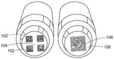
FIG. 1A provides a comparison of the segmented bar code of the present invention on the left side relative to the prior art bar code on the sample tube on the right side.
Fig. 1B illustrates an alternative arrangement of segmented bar code members at the end of a sample tube.
Fig. 1C is a flowchart illustrating an operation of reading the barcode part of fig. 1A and 1B.
Fig. 1D illustrates a possible circuit in the central region of the bottom of the sample tube of fig. 1A and 1B.
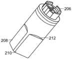
Fig. 2A and 2B are side and end views of an embodiment of the present invention having a flat side at the closed end of the sample tube.
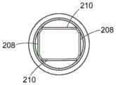
Fig. 3A and 3B are side and end views of a sample tube having a generally rectangular cross-section at its closed end.
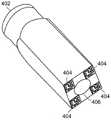
Fig. 4 is a perspective view of a sample tube having a rectangular cross-section closed end on the bottom end and a segmented bar code member.
Fig. 5A and 5B illustrate sample tubes similar to the sample tubes of fig. 2A and 2B with additional orientation surfaces thereon.
Fig. 6A and 6B illustrate an alternative embodiment similar to the embodiment of fig. 3A and 3B with an orientation surface thereon.
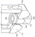
Fig. 7A and 7B are a perspective view and a plan view of a tube clamped by a clamp arm.
Fig. 8A and 8B illustrate another embodiment of a sample tube having an orientation face that is wider near the open end.
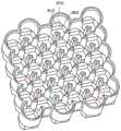
Fig. 9A illustrates a high density rack having complementary faces for supporting the sample tubes of fig. 6A and 6B.
Fig. 9B is an enlarged view of a portion of the shelf of fig. 9A.
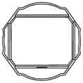
Fig. 9C is a plan view of a portion of the rack of fig. 9A.
FIG. 9D is a side cross-sectional view of the rack of FIG. 9A with sample tubes placed therein.
Fig. 9E is a perspective view of a portion of an alternative rack with spring tabs in a sample tube container.
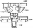
Fig. 10A to 10C are sectional views of the sample tube, the rack, and the jig in the order of moving the sample tube into the jig, and fig. 10D is a plan view of the sample tube placed in the jig.
Fig. 11A to 11D illustrate a two-dimensional barcode including an element for detecting an orientation.
Fig. 12A-12C are perspective, plan, and side views of sample tubes having tabs for locking the sample tubes at a fixed and consistent height within a rack.
Fig. 13A, 13B, and 13C are views of a rack and sample tubes in the rack having tabs for locking the sample tubes at a fixed and consistent height within the rack.
Fig. 14A and 14B are cross-sectional views of a sample tube and rack and enlarged views illustrating an alternative projection for orienting the sample tube.
Fig. 15 is an illustration of a large sample tube storage system.
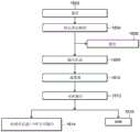
Fig. 16 is a flow chart of automated transfer of sample tubes from the warehouse to the acoustic distribution system of fig. 15 and return of sample tubes to the warehouse.
Fig. 17 is a flow chart for storing sample tubes in the system of fig. 15.
Fig. 18 is a flow chart of processing and outputting sample tubes in the storage system of fig. 15.
Detailed Description
The following is a description of example embodiments of the invention.
Fig. 1A illustrates the ends of four sample tubes. The right tube has a conventional2D barcode grid 106, thebarcode grid 106 encoding a certain amount of data (e.g., 10 characters) in a 14 x 14 grid, e.g., "FR 01036242". As can be seen, the barcode occupies a large portion of thebottom end 108 of the sample tube. As mentioned above, in many applications it is desirable to have an open window at the bottom of the tube without a bar code. For example, the window may provide: light is used to view the sample, to dispense sound, or to interrogate the electronic circuit chip (interrogation). Conventional bar codes cannot be reduced in size so that it can be placed to the periphery relative to the central window without compromising the ability to reliably read the bar code. In some applications, such as in the cryogenic storage of chemical and biological samples, the presence of frost on traditional barcodes, which are merely reduced in size, may make reading the barcode difficult and/or unreliable. To implement thecentral window 104, thecode member 102 shown on the left tube may be sized to fit around the perimeter of the central opening. However, eachbar code component 102 encodes only a portion of the code, for example, half of the full code. For example, twocomponents 102 comprise a portion of a full 10 character code, read and decode the bar code, and concatenate the decoded data from the various components. In one embodiment, eachcode member 102 is a 10 x 10 grid that can encode three alphanumeric characters or six numeric characters. For example, one bar code part may encode "FR 01" while another part encodes "036242". Since only one of the components includes the alphabetical code "FR", the proper order of the concatenated data is apparent. Other indicia for distinguishing between the two components may be used, such as a unique alphanumeric string or symbol in one or both components.
In case only twocomponents 102 are needed to encode the required data, there is room for two additional components. These two additional components may be used to provide redundant data. This is particularly useful because the reduced barcode size is more likely to result in decoding errors. The redundant components allow for additional error checking and even correction.
FIG. 1B shows an alternative layout of four bar code components that can implement thecenter window 112. Possible dimensions are presented in millimeters. As shown, the bottom of the tube may be circular (as illustrated in fig. 1A) or rectangular (as illustrated in fig. 1B).
Fig. 1C illustrates a process of decoding the barcode part of fig. 1A and 1B. At 124, images of the four parts are taken. The image may be an image of the bottom of a single sample tube, but more likely is a single image taken of the bottom of a sample tube of the entire rack. At 126, each of the four barcode components is decoded. By printing the associated pair of bar code parts diagonally, no confusion is caused as to which parts match the pair. In each diagonal pair, at 128, the order is determined by the predetermined character in one of them. Diagonal components are then collocated, at 130, to provide two redundant decoded outputs. These redundant components may be compared in error checking at 132. Assuming the two outputs match, at 134, a single data output is provided. If they do not match, the redundancy code may allow error correction. Otherwise, re-imaging or manual inspection may be performed subsequently.
As shown in fig. 1D, thecircuit chip 116 disposed at the central window may include aprocessor 120, amemory 122, aphotocell 118, and anantenna 124. The photocell is excited by the received laser light. The circuit is powered by light and is capable of emitting a digital RF signal via the antenna. The data may simply be identification information or other sample information. However, the data may also store historical information about the tube and/or about the sample stored within the tube. In particular, the circuit may include atemperature sensor 120, thetemperature sensor 120 being in close proximity to or in contact with the sample stored in the sample cell. This proximity of the temperature sensor to the sample may provide for more accurate temperature measurement and/or evaluation of the sample. In some cases, the temperature sensor and associated circuit chip are disposed at the bottom of the tube such that at least a portion of the sample is proximate to the temperature sensor regardless of the volume of the sample in the tube. In some embodiments, the temperature history of the sample may be retained within the circuit chip of the tube, and/or in a data management system external to the tube. These histories are particularly important in cases where the stored samples are not thermally stable.
The sample tube is generally cylindrical, as illustrated in fig. 1A. However, in some applications, it may be advantageous to have a tube bottom end that is not cylindrical (e.g., a rectangular form with flat sides as illustrated in fig. 2A-6B). For example, in some applications, the tube geometry and/or orientation of the tubes is important. For example, some applications (e.g., dispensing applications such as acoustic distribution) may require knowledge of the physical and/or material properties of the tube (e.g., structural materials, density, physical imperfections, structural material inconsistencies, thickness variations, tube manufacturing variations, etc.) because these properties vary throughout the tube or a portion of the tube. Thus, for some applications, the tube is measured to determine these characteristics. Methods of measuring the tube may include, for example, optical observation or taking acoustic or electromagnetic wave measurements. In many cases, the measurement data will be specific to a particular tube orientation, and the tube orientation will need to be known or maintained according to the requirements of a particular application. The non-cylindrical embodiment enables the tube to be correctly oriented within the scaffold. In the tube of fig. 2A and 2B, opposingflat walls closure 206, such as a screw cap, to be applied to the tube.
Side view fig. 3A and bottom view fig. 3B illustrate an alternative to four flat faces at the bottom end of the tube providing a generally rectangular shape. In this case, the longerflat sides 210 are opposite each other and the shorterflat sides 208 are opposite each other. The substantially rectangular shape with different length opposing sides reduces the number of possible orientations of the tubes in the corresponding racks to only two. In other embodiments, the bottom end of the tube is square in shape, which allows for four possible orientations in the rack. Other tube bottom shapes may only allow a single possible orientation in the rack.
Fig. 4 illustrates such a sample tube: the sample tube has a generally rectangular bottom end, a cylindrical open end with ascrew cap 402, and fourbar code members 404 around the perimeter of acentral window 406. As mentioned, the window may be an optical or acoustic window, or a supporting chip.
Fig. 5A and 5B illustrate a modification of the sample tube of fig. 2A and 2B having a four-part bar code. By virtue of the cylindrical open end of the sample tube, there is a possibility that the sample tube will rotate within the clamp, where the flat face of the bottom end is not aligned with the flat face of the receiving rack. To avoid such rotation, a non-cylindrical surface, in particular a flat sliding pad, is formed around the circumference of the open end of the tube. These faces do not interfere with the cylindrical opening into which the cap is screwed. Even though the externally threaded tube may also include a flat slidingpad 502, the sliding pad would not need to extend all the way to the open end of the tube. In some embodiments, the sliding pad is of the same structural material as the tube and is an integral part of the tube. In other embodiments, the sliding pad may have a different structural material than the tube, and may be integrated with (e.g., co-molded with) the tube or applied separately to the tube.
As illustrated in fig. 7A and 7B, the clamp assembly has corresponding flat faces. The twogripper fingers tube 706. In one embodiment, theclamp fingers tube 706 from the rack between the clamp fingers, and the spring force holds the tube between the clamp fingers. In fig. 7A and 7B, theclamp fingers tube 706 under thecap 708. Each gripper finger has twoplanar faces 710 in thefinger 711 that are complementary to the planar faces 502 of the syringe tube. When the gripper fingers press onto the syringe, the complementary flat surfaces ensure that the syringe remains properly oriented within the arm without rotation. If there is a small amount of rotation while pushing the tube up from the rack into the gripper fingers, the flat side pads will rotate the sample tube back to the correct orientation as the tube comes between the fingers.
Fig. 6A and 6B show a flat slidingpad 602 added to the four flat face embodiment of fig. 3A and 3B. While the sliding pad in each embodiment need not extend the full length of the sample tube, extending the full length simplifies the manufacturing process.
Fig. 8A and 8B illustrate another sliding pad modification of the geometry of fig. 6A and 6B and fig. 3A and 3B. In this embodiment, a generally wider slidingpad 802, for example about 2.5mm wide, is provided at the open end of the sample tube. However, the sliding pad narrows towards thebottom end 804 of the sample tube. The narrow slide pad enables awider chamfer 806 to better support, orient, and/or align the sample tube in the rack. As before, threadedcap 808 closes the end of the sample tube.
Fig. 9A illustrates a high density rack such as a storage rack that may be used in an automated pipe storage system (e.g., a warehouse). It can be seen that each column of tube containers is offset relative to the adjacent columns to increase the density of tubes stored in the rack. Each container can be seen to have fourplanar faces flat face 902 corresponds to the flat slidingpad 602. The chamfer of the sample tube abuts the bearingsurface 912. Each of fig. 9B, 9C, and 9D shows a single tube with acap 916 placed within the rack. Features similar to these can also be used in SBS format.
Fig. 9E shows a standard density rack (e.g., SBS format rack) with several tubes supported inside. The empty container illustrates a further modification in which a spring-loadedtab 918 is present at one of the support faces 912. Thetabs 918 can snap into recesses formed in the sides of the tube to lock the tube in place. If only a single tab and a single recess are provided, it can be ensured that the sample tube is placed in only one orientation.
Fig. 10A, 10B, 10C, and 10D illustrate tube picking sequences with alternative clamp designs. As illustrated in fig. 10A, thetube 1002 is initially seated in arack 1004. Theclamp 1006 has arms that are fixed relative to each other, but support a spring-loadedclip 1008. As shown in fig. 10B, the tube is first pushed up from the rack into theclip 1008 from below the rack with a pusher (not shown). Where rotation is limited by both the bracket and the spring-loaded clip. Thereafter, as illustrated in fig. 10C, the tube is pushed further up into themagazine 1010, themagazine 1010 having aface 1012 that is complementary to a face on the tube to limit tube rotation (fig. 10D).
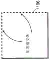
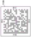
11A, 11B, 11C, and 11D illustrate a conventional bar code that enables the correct orientation of the tube to be detected in accordance with the present invention. As illustrated in fig. 11A, twobars 1104 in thebarcode 1102 identify two edges of the barcode. As illustrated in fig. 11C, the matrix density bars on opposite edges of thebar code 1102 define the rows and columns of the bar code. As shown in fig. 11D, aquiet zone 1108 may surround the barcode. The edges of the 2D code can be detected by the imaging software detecting the quiet zone (i.e. the blank area surrounding the code). Then, two seek bars (finder bar)1104 give orientation. This oriented portion of the bar code is applied to at least one of the bar code components, preferably to all four components.
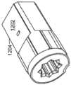
Fig. 12A-14B illustrate additional features for rotating and vertically orienting the sample tube. As illustrated in fig. 12A, 12B, and 12C, lugs 1202 (protrusions) are formed on opposing planar faces at the bottom end of the sample tube. These lugs are received by recesses in the complementary container faces.
As illustrated in fig. 13A, 13B, and 13C, a protrusion may alternatively be formed on a side of the container to fit into a recess in a side of the sample tube.
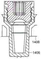
In fig. 14A and 14B, a protrusion is provided in both the tube and the container. Aprotrusion 1402 is disposed onsample tube 1406 and aprotrusion 1404 is disposed oncontainer 1408. Theprotrusion 1404 sits in a depression in the tube and theprotrusion 1402 sits below the rim of the container.
In each of the above embodiments with projections, the material or structure of the container or tube allows some flexing so that the sample tube can be slid into the container. Moreover, the angled face allows the tube to move in the container without initial friction as the protrusion moves into the recess.
Fig. 15 illustrates a complete storage system that can store racks and sample tubes. The storage system includes a freezer 1502 having a number of storage locations (not shown) to store trays filled with sample tubes and/or trays filled with racks of sample tubes. The racks are transported within the warehouse using a robotic transport system. An input/output station behind thegate 1504 allows scientists to place input/output racks into the warehouse 1502. Also within the warehouse is a pick-up station for picking tubes from the input/output racks and placing them into appropriate storage containers or other input/output racks. A suitable input/output bay is described in European patent application No.16275011.1 entitled "Automated Sample Storage System Having Storage Structure with Sub-optical Storage sensitivity", filed on 20/1/2016, the contents of which are hereby incorporated by reference in their entirety. An imager is disposed within the warehouse for reading the 2D barcode from the end of the sample tube while the sample tube is in the rack. The system may also include anacoustic distribution system 1506.
The acoustic distribution station includes aninterface 1508 through which an Automated Interface Module (AIM) automatically outputs storage racks, e.g., trays having a plurality of storage racks, from the warehouse via theinterface 1508. Thestations 1506 include athawing station 1510, alabel printer 1512, acarousel storage 1514, twoacoustic dispensing stations 1516, afilm dispenser 1518 for applying a sealing film on the microplate, atube uncapping device 1520, and astation 1522 for removing the sealing film from the microplate. The racks are moved from station to station by means of a centralrobotic system 1524. Also included, but not shown, is a centrifuge. Additional stations, such asstation 1526, may also be provided for analysis and other processing (e.g., liquid dispensing) of samples contained in the racks or microplates.
A control system 1528 controls all automated operations within the warehouse 1502, and (in some embodiments) peripheral systems such as theacoustic distributor 1506 and thestation 1526. The control system 1528 is typically implemented in software within a hardware system that includes a data processor, associated memory, and input/output devices. The processor routines and data may be stored as a computer program product on a non-transitory computer readable medium. The system may be, for example, a network of independent computers or devices. Included in the system is a database in memory that associates each barcode identifier with, for example, tubes, racks, rack locations, measurement data, cooling, warming and/or processing history, and/or other sample, tube or rack information.
In the exemplary operation illustrated in FIG. 16, the automationinterface module outputs 1602 the trays of the storage rack from the warehouse. At 1604, a central robot from the acoustic distribution system places the rack in the thawing station for a predetermined time or until a predetermined temperature is reached. The tube rack is then optionally transferred to an automatedcentrifuge 1606. The tube rack is then transferred to anautomated decapper 1608 for removal of the tube caps. The rack is sent to anacoustic distributor 1610, where the target microplate is also placed, and the sample is distributed from the source tube to the target plate. The target plate is then brought back to thestorage conveyor 1612 after automated sealing 1614. The racks are then returned to thecap openers 1616 so that the caps of the racks are placed back into the original tubes of the caps, and the racks are returned to the warehouse by means of the AIM.
Traditionally, thawing systems have relied on warm air blown from beneath the sample to accelerate thawing. Other methods include resistance heating, conduction through a medium (e.g., water bath or microwave heating). Sonic energy may also be used to heat samples, including samples in aqueous solutions. Sonic energy can be used to enable the heating and transport of cells without causing damage to the cells. The acoustic energy may limit the creation of hot zones that may result from other types of warming. Thetemperature sensor 122 disposed on thecircuit chip 116 of FIG. 1D may provide real-time temperature feedback from the sample wirelessly. In combination with acoustic heating, samples of a biological sample can be thawed and warmed according to a preprogrammed temperature profile or a preprogrammed temperature threshold, with real-time feedback from a temperature sensor greatly improving the accuracy of thawing and warming. Temperature sensors also provide similar advantages to other heating methods. Real-time temperature feedback from the temperature sensor, which accurately monitors and enables the implementation of pre-programmed temperature profiles or pre-programmed temperature thresholds, can optimize sample (e.g., cell) activity and avoid overheating and/or uneven heating and subsequent possible damage to the sample.
Existing acoustic distribution systems rely on microplates with numerous wells containing source materials/reagents. Thus, a single survey scan of the source plate provides measurement information for all holes in the plate. This information will be stored for a single microplate ID represented by a single barcode on the microplate. In the present system, each sample tube can be delivered on any rack, and therefore measurement data must be retained for each tube. Thus, the measurement data must reference the tube ID, as opposed to a single ID for the entire plate. Furthermore, if the measurement data is to be reused, the orientation of the tubes must be maintained.
FIG. 17 is a flow chart of a process of storing tubes in racks in a storage system. Racks of sample tubes may be input into a tray I/O bank behind thegate 1504 at 1702. Alternatively, a tray with racks may be received 1704 via an Automated Interface Module (AIM) (e.g., via tray interface 1508). In either case, the rack location at the warehouse input may pass through animager 1708, which imager 1708 may image the bar codes at the bottom ends of all the tubes on the rack. The shelves may then be transferred by the robot to afinal storage destination 1710. Alternatively, the sample tubes in one or more racks can be reformatted at 1712 by removing the tubes with grippers at the picker station and placing the tubes back in the same or a different rack as appropriate. After reformatting, the reformatted shelves may be moved by the robot to theirfinal storage position 1714. Optionally, the tubes may be re-imaged at 1716, or the empty racks may be imaged at 1716 to confirm that they are empty. Any shelves to be stored are then moved by the robot to their storage location at 1718.
FIG. 18 is a flow chart illustrating possible automated processing and output of rack-mounted sample tubes within a warehouse. The rack may be removed from the warehouse at 1802 and the rack is handed off to a pick-up station at 1804 for sample reformatting. In sample reformatting, samples to be output are placed on one rack, while samples to be returned to the warehouse are placed on a different rack. Only those samples that need to be processed need to be thawed and then refrozen. The tubes that are not to be exported are placed back intowarehouse 1806. The rack with the tubes to be output is placed on an output tray at 1808, which is moved to animager 1810 where identification and orientation of the appropriate sample tubes is ensured. The tray is moved from the imager to thewarehouse output 1812, from 1812, it may be manually removed from the tray I/O library at 1814, or removed by the AIM at 1816.
At least in the case of acoustic dispensing, it is important to maintain the orientation of the sample tube so that the measurement data can be correctly applied in the dispensing operation. As discussed above, the flat sliding pad on the cylindrical end of the sample tube facilitates proper orientation by preventing rotation of the tube during pick and place operations. The orientation of each tube when it is first loaded into the warehouse is recorded by imaging the distinctive bar code illustrated in fig. 11A-11D. A tube having a square cross-section at the bottom end can have any one of four orientations; however, a tube with a non-square rectangular bottom end has one of only two possible orientations. If any errors are subsequently detected during imaging, the misoriented sample may be retained for human inspection and correction, or a re-measurement by the acoustic dispenser may be requested. In other embodiments, the pick-up station within the storage system may be configured with a rotary clamp or other tube rotation mechanism to automatically reorient the mis-oriented samples detected by the imaging device.
Typical industry standard pipe racks have features that allow the orientation of the full rack to be detected with the aid of an image of the full rack. The user is expected to load the rack in the correct orientation, but if the input is wrong, the error will be detected at the image. The user or system may then correct the orientation of the whole rack. In other embodiments, the storage system may be configured with devices, such as rack carousels, to automatically reorient a misoriented rack detected by the imaging device.
Because existing acoustic distribution systems rely on microplates with many wells containing source materials/reagents, when an acoustic distributor is used to transfer material from the microplate, the entire microplate is exposed even though material is not transferred from each well to the target microplate. By practicing the invention, full or partial racks of desired tubes may be provided, these racks being selected to be contained in the source rack, and/or selectively opened to expose only those samples or reagents desired to be dispensed. Unintended, unwanted samples and reagents are not thawed and/or exposed as in conventional microplate acoustic dispensing.
During acoustic assignment, previously stored measurements may be retrieved based on the identification barcode of the respective tube. These historical measurements can then be used in the distribution process. Alternatively, new data may be obtained by means of measurements. In some embodiments, the warehouse 1502 includes a controller and a data storage system whereby measurement data obtained from a particular tube can be transferred from a measurement device (e.g., acoustic dispenser) and stored. In some cases, the controller and data storage system may assemble a data packet containing data associated with a tube that has been placed into an input/output rack. The data packet will in most cases correlate data associated with a particular tube (e.g., measurement data) with the tube's position in the input/output rack. The controller and data storage system may then transfer the data packets to a device that requires such information (e.g., a distribution device). The data packets may be associated with a particular rack by using a rack barcode, and the device may read the rack barcode and apply the associated data packets as needed for operation of the apparatus.
While the present invention has been particularly shown and described with reference to exemplary embodiments thereof, it will be understood by those of ordinary skill in the art that various changes in form and details may be made therein without departing from the scope of the present invention encompassed by the appended claims.
Claims (17)
1. A sample tube, comprising:
a sidewall that is substantially cylindrical and open at one end and non-cylindrical and closed with a bottom at an opposite end; and
a non-cylindrical face formed in the substantially cylindrical end of the side wall, clamped by a complementary clamp face of a clamp, ensuring correct orientation of the test tube relative to the clamp.
2. The sample tube of claim 1, wherein the bottom end of the sample tube has a rectangular cross-section.
3. The sample tube of claim 2, wherein the non-cylindrical face formed in the generally cylindrical end of the sidewall extends along an edge of the rectangular cross-section at the bottom end of the sample tube.
4. The sample tube of claim 1, wherein the non-cylindrical face is a flat face.
5. The sample tube of claim 1, further comprising a barcode on a bottom end of the sample tube, the barcode comprising elements for determining an orientation of the sample tube.
6. The sample tube of claim 1, further comprising: a protrusion or depression on the sidewall for orienting the sample tube.
7. An acoustic distribution system that processes sample tubes according to claim 1 in a rack.
8. A system for identifying measurement data regarding the sample tubes of claim 1 in a rack, the system configured to:
imaging the barcode of each sample tube in the rack;
measuring a characteristic of a sample tube in the rack; and
storing measurement data in a database for each sample tube identified by the barcode.
9. The system of claim 8 as a component of an acoustic distribution system.
10. The system of claim 8, wherein the characteristic of the sample tube is at least one of a physical characteristic and a structural material.
11. The system of claim 8, the system further configured to: determining an orientation of the sample tube based on orientation elements decoded from a barcode on a bottom end of the sample.
12. The system of claim 8, the system further configured to: placing each sample tube in the rack, the protrusion or depression in each sample tube being complementary to a face of the rack.
13. A system for identifying sample tubes, each sample tube comprising: a two-dimensional barcode on the bottom of the sample tube, the two-dimensional barcode storing data and being readable from below the sample to provide a data output, the barcode comprising a plurality of barcode components positioned towards a perimeter of the bottom, including redundant barcode components on the bottom of the sample tube, the system configured to;
imaging and decoding each bar code component;
combining the data decoded from the plurality of barcode components to provide a complete data output; and
comparing outputs from the redundant bar code components.
14. The system of claim 13, the system configured to: the output of the temperature sensor placed in each sample tube is read wirelessly.
15. The system of claim 13, the system configured to: an acoustic signal is transmitted through an open window in a central region of the bottom of each sample tube to dispense liquid from the sample tube.
16. The system of claim 13, the system further configured to: the orientation of each sample tube is confirmed by decoding the orientation elements of the barcode.
17. A method of orienting sample tubes in a rack, the method comprising the steps of:
providing sample tubes, each sample tube comprising a sidewall that is substantially cylindrical and open at one end and non-cylindrical at an opposite bottom end, the substantially cylindrical end having a non-cylindrical face;
clamping the sample tube from the rack into a clamp having a clamp face complementary to a non-cylindrical face formed in the generally cylindrical end of the sidewall; and
placing the sample tubes in a rack having respective sample tube containers, each sample tube container having a complementary non-cylindrical shape that receives the sample tubes.
Applications Claiming Priority (3)
| Application Number | Priority Date | Filing Date | Title |
|---|---|---|---|
| US201662405714P | 2016-10-07 | 2016-10-07 | |
| US62/405,714 | 2016-10-07 | ||
| CN201780068428.1ACN109922887B (en) | 2016-10-07 | 2017-10-05 | Sample tube and method |
Related Parent Applications (1)
| Application Number | Title | Priority Date | Filing Date |
|---|---|---|---|
| CN201780068428.1ADivisionCN109922887B (en) | 2016-10-07 | 2017-10-05 | Sample tube and method |
Publications (1)
| Publication Number | Publication Date |
|---|---|
| CN114037030Atrue CN114037030A (en) | 2022-02-11 |
Family
ID=60245188
Family Applications (2)
| Application Number | Title | Priority Date | Filing Date |
|---|---|---|---|
| CN202111312511.3APendingCN114037030A (en) | 2016-10-07 | 2017-10-05 | Sample tube, acoustic distribution system, system for identifying sample tube and method for orienting sample tube |
| CN201780068428.1AActiveCN109922887B (en) | 2016-10-07 | 2017-10-05 | Sample tube and method |
Family Applications After (1)
| Application Number | Title | Priority Date | Filing Date |
|---|---|---|---|
| CN201780068428.1AActiveCN109922887B (en) | 2016-10-07 | 2017-10-05 | Sample tube and method |
Country Status (5)
| Country | Link |
|---|---|
| US (2) | US10677810B2 (en) |
| EP (1) | EP3523045B1 (en) |
| JP (3) | JP7080226B2 (en) |
| CN (2) | CN114037030A (en) |
| WO (1) | WO2018067795A2 (en) |
Families Citing this family (26)
| Publication number | Priority date | Publication date | Assignee | Title |
|---|---|---|---|---|
| EP3281018B1 (en)* | 2015-04-07 | 2023-06-07 | Gen-Probe Incorporated | Systems and methods for reading machine-readable labels on sample receptacles |
| CN107683415B (en) | 2016-03-14 | 2021-11-23 | 神户仿生机械株式会社 | Automatic sample storage body processing system and sample storage body used for the system |
| JP6732331B2 (en)* | 2016-10-03 | 2020-07-29 | 溝口 さとし | System for preventing sample mix-up in pathological diagnosis |
| CN114037030A (en) | 2016-10-07 | 2022-02-11 | 布鲁克斯自动化公司 | Sample tube, acoustic distribution system, system for identifying sample tube and method for orienting sample tube |
| WO2018232364A1 (en) | 2017-06-16 | 2018-12-20 | Beckman Coulter, Inc. | Apparatus and method for handling sample containers |
| USD938612S1 (en) | 2017-06-16 | 2021-12-14 | Beckman Coulter, Inc. | Sample rack |
| US10598637B2 (en)* | 2017-07-18 | 2020-03-24 | Perkinelmer Health Sciences, Inc. | Automated thermal desorption systems configured to determine sample tube orientation and/or cap presence, and related methods |
| WO2019060275A1 (en) | 2017-09-21 | 2019-03-28 | Becton, Dickinson And Company | Demarcation template for hazardous contaminant testing |
| USD859683S1 (en) | 2017-09-21 | 2019-09-10 | Becton, Dickinson And Company | Collection device |
| US11391748B2 (en) | 2017-09-21 | 2022-07-19 | Becton, Dickinson And Company | High dynamic range assays in hazardous contaminant testing |
| US10816516B2 (en) | 2018-03-28 | 2020-10-27 | Perkinelmer Health Sciences, Inc. | Autosamplers and gas chromatographic systems and methods including same |
| CZ308140B6 (en)* | 2018-08-23 | 2020-01-22 | Geneproof A.S. | Test tube rack with lids |
| WO2020072945A1 (en) | 2018-10-05 | 2020-04-09 | TMRW Life Sciences, Inc. | Apparatus to preserve and identify biological samples at cryogenic conditions |
| JP7503074B2 (en)* | 2019-03-20 | 2024-06-19 | ベクトン・ディキンソン・アンド・カンパニー | Sampling systems and techniques for the detection of hazardous contaminants |
| MX2022005127A (en) | 2019-10-29 | 2022-08-04 | Tmrw Life Sciences Inc | Apparatus to facilitate transfer of biological specimens stored at cryogenic conditions. |
| GB2592590B (en)* | 2020-03-02 | 2024-02-14 | Agilent Technologies Inc | Sample processing with information detection during transfer of a sample container |
| AU2021276247A1 (en) | 2020-05-18 | 2022-11-17 | TMRW Life Sciences, Inc. | Handling and tracking of biological specimens for cryogenic storage |
| USD951481S1 (en) | 2020-09-01 | 2022-05-10 | TMRW Life Sciences, Inc. | Cryogenic vial |
| WO2022066943A1 (en) | 2020-09-24 | 2022-03-31 | TMRW Life Sciences, Inc. | Workstation and apparatus to facilitate transfer of biological specimens stored at cryogenic conditions |
| AU2021351505B2 (en) | 2020-10-02 | 2024-11-21 | TMRW Life Sciences, Inc. | Interrogation device and/or system having alignment feature(s) for wireless transponder tagged specimen containers and/or carriers |
| USD963194S1 (en) | 2020-12-09 | 2022-09-06 | TMRW Life Sciences, Inc. | Cryogenic vial carrier |
| EP4259333A4 (en) | 2020-12-10 | 2024-11-06 | TMRW Life Sciences, Inc. | SAMPLE HOLDER WITH WIRELESS TRANSPONDER FOR ATTACHMENT TO A COLLECTION BODY FOR CHILDREN |
| CA3202347A1 (en) | 2021-01-13 | 2022-07-21 | James Norman Craven | Systems, apparatus and methods to pick and/or place specimen containers |
| US12412651B2 (en)* | 2021-03-23 | 2025-09-09 | Quantgene Inc. | Sample tube rack based transfer, management and tracking |
| GB2608611A (en)* | 2021-07-05 | 2023-01-11 | Sec Dep For Health And Social Care | Sample collection tube |
| IT202200027408A1 (en)* | 2022-12-30 | 2024-06-30 | Twin Helix Srl | regulatory compliant method for tracking, monitoring and managing biological samples and/or libraries of molecules and related information |
Citations (10)
| Publication number | Priority date | Publication date | Assignee | Title |
|---|---|---|---|---|
| US4060457A (en)* | 1975-01-07 | 1977-11-29 | Ichiro Kojima | Apparatus for growing animal cells |
| US20020098126A1 (en)* | 2000-11-29 | 2002-07-25 | Advanced Biotechnologies Limited | Tubes |
| US20070053794A1 (en)* | 2005-09-08 | 2007-03-08 | Beckman Coulter, Inc. | Sample identification system having plural readers |
| US20080254544A1 (en)* | 2007-04-12 | 2008-10-16 | Modzelewski Brent E | Error detection and rejection for a diagnostic testing system |
| US20100018330A1 (en)* | 2008-07-25 | 2010-01-28 | Christian Marty | Method and laboratory system for handling sample tubes and an image analyzing unit |
| US20100294050A1 (en)* | 2009-05-20 | 2010-11-25 | Protedyne Corporation | System and method for vessel alignment |
| US20120051986A1 (en)* | 2010-08-31 | 2012-03-01 | Wheaton Industries, Inc. | Rack configured to support vials with identification indicia exposed |
| US20140374480A1 (en)* | 2012-02-03 | 2014-12-25 | Siemens Healthcare Diagnostics Inc. | Barcode reading test tube holder |
| WO2015108807A1 (en)* | 2014-01-14 | 2015-07-23 | Labcyte, Inc. | Sample containers with identification mark |
| US20150273468A1 (en)* | 2014-03-28 | 2015-10-01 | Brooks Automation, Inc. | Sample storage and retrieval system |
Family Cites Families (49)
| Publication number | Priority date | Publication date | Assignee | Title |
|---|---|---|---|---|
| FR1036242A (en) | 1951-04-27 | 1953-09-04 | Rolling bevel reservoir case for color eyeshadows | |
| DE4425277A1 (en) | 1994-07-16 | 1996-01-18 | Boehringer Mannheim Gmbh | Packaging system for liquid reagents |
| US5540331A (en)* | 1994-12-30 | 1996-07-30 | Evergreen Industries, Inc. | Leak proof vial for microscope slides |
| NL1003726C2 (en) | 1996-08-01 | 1998-02-05 | Micronic B V | Test tube with optically readable coding. |
| JP3920420B2 (en)* | 1996-10-08 | 2007-05-30 | 富士通株式会社 | EH matching device, microwave automatic matching method, semiconductor manufacturing equipment |
| US6802454B1 (en) | 1999-07-27 | 2004-10-12 | International Business Machines Corporation | Interleaved sequencing method for multiple two-dimensional scanning codes |
| US6372293B1 (en) | 1999-09-20 | 2002-04-16 | Matrix Technologies Corporation | Test tube with data matrix code markings |
| SE0004353L (en) | 1999-12-06 | 2001-06-07 | Greiner Bio One Gmbh | Device in the form of a vessel and / or seal |
| AU2001238996A1 (en) | 2000-03-20 | 2001-10-03 | Mediscan Gmbh | Method for individualising objects |
| US6818859B2 (en) | 2001-08-27 | 2004-11-16 | Q.I.S., Inc. | Glass vials with data matrix codes and method of making the same |
| JP2003083984A (en) | 2001-09-12 | 2003-03-19 | Aloka Co Ltd | Specimen container and rack |
| DE10162810A1 (en) | 2001-12-19 | 2003-07-03 | Linhardt Gmbh & Co Kg | Method for producing packaging, in particular tube or tube packaging, device for carrying out the method and packaging |
| US20040018506A1 (en) | 2002-01-25 | 2004-01-29 | Koehler Ryan T. | Methods for placing, accepting, and filling orders for products and services |
| JP4168091B2 (en) | 2002-05-27 | 2008-10-22 | 吉秀 西川 | Mini tube |
| WO2005036454A1 (en) | 2003-09-23 | 2005-04-21 | Secure Symbology, Inc. | Method for improving security and enhancing information storage capability |
| JP2005172682A (en) | 2003-12-12 | 2005-06-30 | Fukae Chemical Research:Kk | Sample storage tube |
| KR100679630B1 (en) | 2004-07-27 | 2007-02-07 | 주식회사 칼라짚미디어 | Hybrid tag interface system and interfacing method |
| US7543748B2 (en) | 2005-02-16 | 2009-06-09 | Pisafe, Inc. | Method and system for creating and using redundant and high capacity barcodes |
| KR101260400B1 (en)* | 2005-04-01 | 2013-05-09 | 미쓰비시 가가쿠 메디엔스 가부시키가이샤 | Biosample Multiple Autoanalyzer, Method of Autoanalysis and Reaction Cuvette |
| FR2885248B1 (en) | 2005-04-28 | 2007-08-10 | Becton Dickinson France Soc Pa | METHOD FOR IDENTIFYING MULTIPLICITY OF CONTAINERS AND / OR FINISHED ARTICLES OBTAINED FROM SAID CONTAINERS |
| US20070036686A1 (en) | 2005-05-31 | 2007-02-15 | Mehdi Hatamian | Systems for tracking and testing of medical specimens and data |
| JP4473189B2 (en)* | 2005-07-22 | 2010-06-02 | 株式会社椿本チエイン | Drug storage system for drug discovery |
| US7428996B2 (en) | 2005-11-17 | 2008-09-30 | Pitney Bowes Inc. | Method and system for encoding information into a bar code with different module size |
| JP4689528B2 (en)* | 2006-05-01 | 2011-05-25 | 株式会社椿本チエイン | Drug storage system for drug discovery |
| US7562811B2 (en) | 2007-01-18 | 2009-07-21 | Varcode Ltd. | System and method for improved quality management in a product logistic chain |
| JP2009537038A (en) | 2006-05-07 | 2009-10-22 | バーコード リミティド | System and method for improving quality control in a product logistic chain |
| AU2007289198A1 (en) | 2006-08-30 | 2008-03-06 | Becton, Dickinson And Company | Multiple barcode format labelling system and method |
| EP2084521B1 (en)* | 2006-11-21 | 2018-06-20 | GE Healthcare Bio-Sciences Corp. | Assembling and utilizing rfid sensors in containers |
| US20080217391A1 (en) | 2007-01-31 | 2008-09-11 | Intellidot Corporation | Optical markings |
| JP2008191070A (en) | 2007-02-07 | 2008-08-21 | Aloka Co Ltd | Sample container and sample container rack |
| US8710958B2 (en)* | 2008-07-10 | 2014-04-29 | Abbott Laboratories | Containers having radio frequency identification tags and method of applying radio frequency identification tags to containers |
| CH699407A1 (en) | 2008-08-25 | 2010-02-26 | Tecan Trading Ag | Sample tube with labeling. |
| FR2957536A1 (en) | 2010-03-18 | 2011-09-23 | Sas Laboratoire | Test tubes for containing e.g. blood, to be analyzed in laboratory, has reading and/or writing unit that reads and/or writes identifier stored and/or to be stored in chip, where unit is located in circulation path of tube |
| EP2386356A1 (en) | 2010-05-12 | 2011-11-16 | ABB Technology AG | Sample remover container for a liquid with container tag |
| US8965795B2 (en) | 2010-10-12 | 2015-02-24 | Jill Blaine | Methods and systems for labeling labware |
| EP2455761B1 (en) | 2010-11-23 | 2018-08-08 | Hach Lange GmbH | Method for detecting an optical marking on a laboratory analysis vessel |
| JP5517897B2 (en)* | 2010-11-24 | 2014-06-11 | 株式会社椿本チエイン | Drug micro tube cap removal device |
| US9358091B2 (en) | 2011-04-18 | 2016-06-07 | Inguran, Llc | Two-dimensional bar codes in assisted reproductive technologies |
| EP2728363B1 (en) | 2011-06-28 | 2021-06-02 | Kabushiki Kaisha Yaskawa Denki | Robot hand and robot |
| US8935001B2 (en) | 2012-03-29 | 2015-01-13 | bioMeriéux, Inc. | System and method for establishing and/or maintaining proper alignment of a robotic transfer mechanism |
| GB201301188D0 (en)* | 2013-01-23 | 2013-03-06 | Cryogatt Systems Ltd | RFID tag |
| DE102013206967A1 (en) | 2013-04-17 | 2014-11-06 | Hamilton Bonaduz Ag | Sample container with several detection patterns |
| CN103521278B (en) | 2013-10-18 | 2015-06-17 | 杭州百伴生物技术有限公司 | Biological sample storage pipe with identification code and manufacturing method thereof |
| US10592793B2 (en) | 2014-01-14 | 2020-03-17 | Labcyte Inc. | Sample containers having identification marks embedded therein and being adapted for acoustic ejections |
| JP5673879B1 (en)* | 2014-03-31 | 2015-02-18 | 第一実業株式会社 | Tube handling device |
| WO2016157898A1 (en) | 2015-03-30 | 2016-10-06 | パナソニックヘルスケアホールディングス株式会社 | Container management apparatus and wireless tag |
| WO2017066116A1 (en)* | 2015-10-12 | 2017-04-20 | Labcyte, Inc. | Systems and methods for tagging and acoustically characterizing containers |
| CN107683415B (en) | 2016-03-14 | 2021-11-23 | 神户仿生机械株式会社 | Automatic sample storage body processing system and sample storage body used for the system |
| CN114037030A (en) | 2016-10-07 | 2022-02-11 | 布鲁克斯自动化公司 | Sample tube, acoustic distribution system, system for identifying sample tube and method for orienting sample tube |
- 2017
- 2017-10-05CNCN202111312511.3Apatent/CN114037030A/enactivePending
- 2017-10-05JPJP2019518434Apatent/JP7080226B2/enactiveActive
- 2017-10-05WOPCT/US2017/055300patent/WO2018067795A2/ennot_activeCeased
- 2017-10-05CNCN201780068428.1Apatent/CN109922887B/enactiveActive
- 2017-10-05USUS15/725,497patent/US10677810B2/enactiveActive
- 2017-10-05EPEP17794127.5Apatent/EP3523045B1/enactiveActive
- 2020
- 2020-05-12USUS16/872,809patent/US12265094B2/enactiveActive
- 2022
- 2022-05-24JPJP2022084328Apatent/JP2022109316A/enactivePending
- 2024
- 2024-06-27JPJP2024104066Apatent/JP2024120094A/enactivePending
Patent Citations (10)
| Publication number | Priority date | Publication date | Assignee | Title |
|---|---|---|---|---|
| US4060457A (en)* | 1975-01-07 | 1977-11-29 | Ichiro Kojima | Apparatus for growing animal cells |
| US20020098126A1 (en)* | 2000-11-29 | 2002-07-25 | Advanced Biotechnologies Limited | Tubes |
| US20070053794A1 (en)* | 2005-09-08 | 2007-03-08 | Beckman Coulter, Inc. | Sample identification system having plural readers |
| US20080254544A1 (en)* | 2007-04-12 | 2008-10-16 | Modzelewski Brent E | Error detection and rejection for a diagnostic testing system |
| US20100018330A1 (en)* | 2008-07-25 | 2010-01-28 | Christian Marty | Method and laboratory system for handling sample tubes and an image analyzing unit |
| US20100294050A1 (en)* | 2009-05-20 | 2010-11-25 | Protedyne Corporation | System and method for vessel alignment |
| US20120051986A1 (en)* | 2010-08-31 | 2012-03-01 | Wheaton Industries, Inc. | Rack configured to support vials with identification indicia exposed |
| US20140374480A1 (en)* | 2012-02-03 | 2014-12-25 | Siemens Healthcare Diagnostics Inc. | Barcode reading test tube holder |
| WO2015108807A1 (en)* | 2014-01-14 | 2015-07-23 | Labcyte, Inc. | Sample containers with identification mark |
| US20150273468A1 (en)* | 2014-03-28 | 2015-10-01 | Brooks Automation, Inc. | Sample storage and retrieval system |
Also Published As
| Publication number | Publication date |
|---|---|
| US12265094B2 (en) | 2025-04-01 |
| JP2019529938A (en) | 2019-10-17 |
| US10677810B2 (en) | 2020-06-09 |
| US20200271676A1 (en) | 2020-08-27 |
| WO2018067795A3 (en) | 2018-05-17 |
| CN109922887A (en) | 2019-06-21 |
| JP7080226B2 (en) | 2022-06-03 |
| JP2022109316A (en) | 2022-07-27 |
| EP3523045B1 (en) | 2023-08-02 |
| JP2024120094A (en) | 2024-09-03 |
| US20180100868A1 (en) | 2018-04-12 |
| EP3523045A2 (en) | 2019-08-14 |
| WO2018067795A2 (en) | 2018-04-12 |
| CN109922887B (en) | 2021-11-26 |
Similar Documents
| Publication | Publication Date | Title |
|---|---|---|
| CN109922887B (en) | Sample tube and method | |
| JP6625713B2 (en) | Rack orientation detection using multiple tags | |
| JP6148698B2 (en) | System for tracking liquid containers in laboratory automatic analyzers by wireless recognition | |
| US8035485B2 (en) | System for tracking vessels in automated laboratory analyzers by radio frequency identification | |
| JP5167258B2 (en) | Modular storage system for laboratory fluids | |
| CN107407690A (en) | Specimen transporting device and specimen transporting method | |
| US20110095864A1 (en) | Laboratory Device, Laboratory Rack Assembly and Method for Coupling an RFID Chip | |
| WO2001056753A1 (en) | Robot mounted barcode reader | |
| WO2002090996A2 (en) | Sample presentation unit |
Legal Events
| Date | Code | Title | Description |
|---|---|---|---|
| PB01 | Publication | ||
| PB01 | Publication | ||
| SE01 | Entry into force of request for substantive examination | ||
| SE01 | Entry into force of request for substantive examination | ||
| CB02 | Change of applicant information | ||
| CB02 | Change of applicant information | Country or region after:U.S.A. Address after:Massachusetts, USA Applicant after:Anshengda Co.,Ltd. Address before:Massachusetts, USA Applicant before:BROOKS AUTOMATION, Inc. Country or region before:U.S.A. | |
| TA01 | Transfer of patent application right | ||
| TA01 | Transfer of patent application right | Effective date of registration:20240703 Address after:Massachusetts, USA Applicant after:Anshengda USA Co.,Ltd. Country or region after:U.S.A. Address before:Massachusetts, USA Applicant before:Anshengda Co.,Ltd. Country or region before:U.S.A. |