CN1140304A - Optical recording medium - Google Patents
Optical recording mediumDownload PDFInfo
- Publication number
- CN1140304A CN1140304ACN95116362ACN95116362ACN1140304ACN 1140304 ACN1140304 ACN 1140304ACN 95116362 ACN95116362 ACN 95116362ACN 95116362 ACN95116362 ACN 95116362ACN 1140304 ACN1140304 ACN 1140304A
- Authority
- CN
- China
- Prior art keywords
- recording medium
- optical recording
- recording
- groove
- layer
- Prior art date
- Legal status (The legal status is an assumption and is not a legal conclusion. Google has not performed a legal analysis and makes no representation as to the accuracy of the status listed.)
- Pending
Links
- 230000003287optical effectEffects0.000titleclaimsabstractdescription141
- 239000010410layerSubstances0.000claimsabstractdescription196
- 239000000758substrateSubstances0.000claimsabstractdescription115
- 239000011241protective layerSubstances0.000claimsabstractdescription62
- 239000002184metalSubstances0.000claimsabstractdescription20
- 229910052751metalInorganic materials0.000claimsabstractdescription20
- 229910004298SiO 2Inorganic materials0.000claimsdescription22
- 238000002844meltingMethods0.000claimsdescription19
- 230000008018meltingEffects0.000claimsdescription19
- 238000002425crystallisationMethods0.000claimsdescription13
- 230000008025crystallizationEffects0.000claimsdescription13
- 229910052715tantalumInorganic materials0.000claimsdescription13
- 229910045601alloyInorganic materials0.000claimsdescription12
- 239000000956alloySubstances0.000claimsdescription12
- 229910052719titaniumInorganic materials0.000claimsdescription12
- 229910052782aluminiumInorganic materials0.000claimsdescription8
- 230000001678irradiating effectEffects0.000claimsdescription8
- 229910052732germaniumInorganic materials0.000claimsdescription6
- 229910052787antimonyInorganic materials0.000claimsdescription5
- 229910052714telluriumInorganic materials0.000claimsdescription5
- -1composed of GWInorganic materials0.000claims1
- 238000007789sealingMethods0.000claims1
- 239000011295pitchSubstances0.000description71
- 230000008859changeEffects0.000description31
- 238000000034methodMethods0.000description29
- 239000000463materialSubstances0.000description26
- 238000007726management methodMethods0.000description23
- 239000010408filmSubstances0.000description20
- 229920005989resinPolymers0.000description17
- 239000011347resinSubstances0.000description17
- 230000000694effectsEffects0.000description15
- 230000035945sensitivityEffects0.000description15
- 238000004364calculation methodMethods0.000description13
- 238000012217deletionMethods0.000description11
- 201000009310astigmatismDiseases0.000description10
- 230000037430deletionEffects0.000description10
- 239000004417polycarbonateSubstances0.000description10
- 229920000515polycarbonatePolymers0.000description10
- 230000003252repetitive effectEffects0.000description10
- 238000005520cutting processMethods0.000description9
- 230000008901benefitEffects0.000description8
- 230000007423decreaseEffects0.000description8
- 239000000203mixtureSubstances0.000description8
- 238000005070samplingMethods0.000description7
- 230000000052comparative effectEffects0.000description6
- 239000011521glassSubstances0.000description6
- 238000009792diffusion processMethods0.000description5
- 238000009826distributionMethods0.000description5
- 238000005259measurementMethods0.000description5
- 230000002441reversible effectEffects0.000description5
- 238000004544sputter depositionMethods0.000description5
- 229910000763AgInSbTeInorganic materials0.000description4
- 229910000838Al alloyInorganic materials0.000description4
- 238000005516engineering processMethods0.000description4
- 238000010438heat treatmentMethods0.000description4
- 238000001755magnetron sputter depositionMethods0.000description4
- 230000000704physical effectEffects0.000description4
- 229920005668polycarbonate resinPolymers0.000description4
- 239000004431polycarbonate resinSubstances0.000description4
- 229920000098polyolefinPolymers0.000description4
- 230000001681protective effectEffects0.000description4
- 229910000618GeSbTeInorganic materials0.000description3
- 230000015572biosynthetic processEffects0.000description3
- 230000006866deteriorationEffects0.000description3
- 238000010586diagramMethods0.000description3
- 238000002474experimental methodMethods0.000description3
- 238000001746injection mouldingMethods0.000description3
- 238000012545processingMethods0.000description3
- 239000004065semiconductorSubstances0.000description3
- 238000004904shorteningMethods0.000description3
- 230000007704transitionEffects0.000description3
- 230000009286beneficial effectEffects0.000description2
- 229910052791calciumInorganic materials0.000description2
- 230000015556catabolic processEffects0.000description2
- 150000001875compoundsChemical class0.000description2
- 238000006731degradation reactionMethods0.000description2
- 239000003989dielectric materialSubstances0.000description2
- 230000002349favourable effectEffects0.000description2
- 230000006870functionEffects0.000description2
- 229910052749magnesiumInorganic materials0.000description2
- 150000001247metal acetylidesChemical class0.000description2
- 150000002736metal compoundsChemical class0.000description2
- 239000007769metal materialSubstances0.000description2
- 238000000465mouldingMethods0.000description2
- 229910052758niobiumInorganic materials0.000description2
- 150000004767nitridesChemical class0.000description2
- 239000004033plasticSubstances0.000description2
- 230000010287polarizationEffects0.000description2
- 230000008569processEffects0.000description2
- 238000010791quenchingMethods0.000description2
- 238000002310reflectometryMethods0.000description2
- 238000011160researchMethods0.000description2
- 229910052710siliconInorganic materials0.000description2
- 150000003568thioethersChemical class0.000description2
- 238000012546transferMethods0.000description2
- 229910052720vanadiumInorganic materials0.000description2
- 229910052684CeriumInorganic materials0.000description1
- 206010010071ComaDiseases0.000description1
- 229910052691ErbiumInorganic materials0.000description1
- 229910005900GeTeInorganic materials0.000description1
- 229910052689HolmiumInorganic materials0.000description1
- 229910052769YtterbiumInorganic materials0.000description1
- 238000002679ablationMethods0.000description1
- 239000000853adhesiveSubstances0.000description1
- 230000001070adhesive effectEffects0.000description1
- 230000004075alterationEffects0.000description1
- 238000004458analytical methodMethods0.000description1
- 238000000137annealingMethods0.000description1
- 101150059062apln geneProteins0.000description1
- 238000013459approachMethods0.000description1
- 229910052785arsenicInorganic materials0.000description1
- QVGXLLKOCUKJST-UHFFFAOYSA-Natomic oxygenChemical compound[O]QVGXLLKOCUKJST-UHFFFAOYSA-N0.000description1
- 229910052798chalcogenInorganic materials0.000description1
- 150000001787chalcogensChemical class0.000description1
- 238000006243chemical reactionMethods0.000description1
- 229910052804chromiumInorganic materials0.000description1
- 230000006835compressionEffects0.000description1
- 238000007906compressionMethods0.000description1
- 238000005094computer simulationMethods0.000description1
- 238000011109contaminationMethods0.000description1
- 238000001816coolingMethods0.000description1
- 229910052802copperInorganic materials0.000description1
- 239000013078crystalSubstances0.000description1
- 238000013500data storageMethods0.000description1
- 238000000354decomposition reactionMethods0.000description1
- 238000013461designMethods0.000description1
- 238000001514detection methodMethods0.000description1
- 230000002542deteriorative effectEffects0.000description1
- 238000011161developmentMethods0.000description1
- 238000002050diffraction methodMethods0.000description1
- 230000008030eliminationEffects0.000description1
- 238000003379elimination reactionMethods0.000description1
- 230000003628erosive effectEffects0.000description1
- 238000001125extrusionMethods0.000description1
- 150000002222fluorine compoundsChemical class0.000description1
- 229910052737goldInorganic materials0.000description1
- 229910052735hafniumInorganic materials0.000description1
- 230000017525heat dissipationEffects0.000description1
- 238000005338heat storageMethods0.000description1
- 230000006872improvementEffects0.000description1
- 229910052738indiumInorganic materials0.000description1
- WPYVAWXEWQSOGY-UHFFFAOYSA-Nindium antimonideChemical compound[Sb]#[In]WPYVAWXEWQSOGY-UHFFFAOYSA-N0.000description1
- 238000002347injectionMethods0.000description1
- 239000007924injectionSubstances0.000description1
- 239000011229interlayerSubstances0.000description1
- 238000002955isolationMethods0.000description1
- 229910052746lanthanumInorganic materials0.000description1
- 229910052745leadInorganic materials0.000description1
- 230000005389magnetismEffects0.000description1
- 229910052748manganeseInorganic materials0.000description1
- 238000004519manufacturing processMethods0.000description1
- 239000011159matrix materialSubstances0.000description1
- 230000007246mechanismEffects0.000description1
- 229910044991metal oxideInorganic materials0.000description1
- 150000004706metal oxidesChemical class0.000description1
- 238000000386microscopyMethods0.000description1
- 229910052759nickelInorganic materials0.000description1
- 230000003647oxidationEffects0.000description1
- 238000007254oxidation reactionMethods0.000description1
- 229910052760oxygenInorganic materials0.000description1
- 239000001301oxygenSubstances0.000description1
- 229910052763palladiumInorganic materials0.000description1
- 229910052697platinumInorganic materials0.000description1
- 238000002360preparation methodMethods0.000description1
- 230000000171quenching effectEffects0.000description1
- 238000001953recrystallisationMethods0.000description1
- 229910052706scandiumInorganic materials0.000description1
- 229910052711seleniumInorganic materials0.000description1
- SBIBMFFZSBJNJF-UHFFFAOYSA-Nselenium;zincChemical compound[Se]=[Zn]SBIBMFFZSBJNJF-UHFFFAOYSA-N0.000description1
- 238000000926separation methodMethods0.000description1
- 229910052709silverInorganic materials0.000description1
- 239000002356single layerSubstances0.000description1
- 239000007787solidSubstances0.000description1
- 239000000243solutionSubstances0.000description1
- 230000005236sound signalEffects0.000description1
- 238000004611spectroscopical analysisMethods0.000description1
- 238000005507sprayingMethods0.000description1
- 238000003860storageMethods0.000description1
- 229910052712strontiumInorganic materials0.000description1
- 239000000126substanceSubstances0.000description1
- 229910052717sulfurInorganic materials0.000description1
- 238000004781supercoolingMethods0.000description1
- 239000013589supplementSubstances0.000description1
- 229920003051synthetic elastomerPolymers0.000description1
- 239000010409thin filmSubstances0.000description1
- 229910052718tinInorganic materials0.000description1
- 238000004804windingMethods0.000description1
- 229910052727yttriumInorganic materials0.000description1
Images


Classifications
- G—PHYSICS
- G11—INFORMATION STORAGE
- G11B—INFORMATION STORAGE BASED ON RELATIVE MOVEMENT BETWEEN RECORD CARRIER AND TRANSDUCER
- G11B5/00—Recording by magnetisation or demagnetisation of a record carrier; Reproducing by magnetic means; Record carriers therefor
- G11B5/62—Record carriers characterised by the selection of the material
- G—PHYSICS
- G11—INFORMATION STORAGE
- G11B—INFORMATION STORAGE BASED ON RELATIVE MOVEMENT BETWEEN RECORD CARRIER AND TRANSDUCER
- G11B7/00—Recording or reproducing by optical means, e.g. recording using a thermal beam of optical radiation by modifying optical properties or the physical structure, reproducing using an optical beam at lower power by sensing optical properties; Record carriers therefor
- G11B7/24—Record carriers characterised by shape, structure or physical properties, or by the selection of the material
- G—PHYSICS
- G11—INFORMATION STORAGE
- G11B—INFORMATION STORAGE BASED ON RELATIVE MOVEMENT BETWEEN RECORD CARRIER AND TRANSDUCER
- G11B7/00—Recording or reproducing by optical means, e.g. recording using a thermal beam of optical radiation by modifying optical properties or the physical structure, reproducing using an optical beam at lower power by sensing optical properties; Record carriers therefor
- G11B7/007—Arrangement of the information on the record carrier, e.g. form of tracks, actual track shape, e.g. wobbled, or cross-section, e.g. v-shaped; Sequential information structures, e.g. sectoring or header formats within a track
- G11B7/00718—Groove and land recording, i.e. user data recorded both in the grooves and on the lands
- G—PHYSICS
- G11—INFORMATION STORAGE
- G11B—INFORMATION STORAGE BASED ON RELATIVE MOVEMENT BETWEEN RECORD CARRIER AND TRANSDUCER
- G11B7/00—Recording or reproducing by optical means, e.g. recording using a thermal beam of optical radiation by modifying optical properties or the physical structure, reproducing using an optical beam at lower power by sensing optical properties; Record carriers therefor
- G11B7/24—Record carriers characterised by shape, structure or physical properties, or by the selection of the material
- G11B7/2407—Tracks or pits; Shape, structure or physical properties thereof
- G11B7/24073—Tracks
- G11B7/24079—Width or depth
- G—PHYSICS
- G11—INFORMATION STORAGE
- G11B—INFORMATION STORAGE BASED ON RELATIVE MOVEMENT BETWEEN RECORD CARRIER AND TRANSDUCER
- G11B7/00—Recording or reproducing by optical means, e.g. recording using a thermal beam of optical radiation by modifying optical properties or the physical structure, reproducing using an optical beam at lower power by sensing optical properties; Record carriers therefor
- G11B7/004—Recording, reproducing or erasing methods; Read, write or erase circuits therefor
- G11B7/0045—Recording
- G11B7/00454—Recording involving phase-change effects
- G—PHYSICS
- G11—INFORMATION STORAGE
- G11B—INFORMATION STORAGE BASED ON RELATIVE MOVEMENT BETWEEN RECORD CARRIER AND TRANSDUCER
- G11B7/00—Recording or reproducing by optical means, e.g. recording using a thermal beam of optical radiation by modifying optical properties or the physical structure, reproducing using an optical beam at lower power by sensing optical properties; Record carriers therefor
- G11B7/004—Recording, reproducing or erasing methods; Read, write or erase circuits therefor
- G11B7/006—Overwriting
- G—PHYSICS
- G11—INFORMATION STORAGE
- G11B—INFORMATION STORAGE BASED ON RELATIVE MOVEMENT BETWEEN RECORD CARRIER AND TRANSDUCER
- G11B7/00—Recording or reproducing by optical means, e.g. recording using a thermal beam of optical radiation by modifying optical properties or the physical structure, reproducing using an optical beam at lower power by sensing optical properties; Record carriers therefor
- G11B7/24—Record carriers characterised by shape, structure or physical properties, or by the selection of the material
- G11B7/241—Record carriers characterised by shape, structure or physical properties, or by the selection of the material characterised by the selection of the material
- G11B7/242—Record carriers characterised by shape, structure or physical properties, or by the selection of the material characterised by the selection of the material of recording layers
- G11B7/243—Record carriers characterised by shape, structure or physical properties, or by the selection of the material characterised by the selection of the material of recording layers comprising inorganic materials only, e.g. ablative layers
- G—PHYSICS
- G11—INFORMATION STORAGE
- G11B—INFORMATION STORAGE BASED ON RELATIVE MOVEMENT BETWEEN RECORD CARRIER AND TRANSDUCER
- G11B7/00—Recording or reproducing by optical means, e.g. recording using a thermal beam of optical radiation by modifying optical properties or the physical structure, reproducing using an optical beam at lower power by sensing optical properties; Record carriers therefor
- G11B7/24—Record carriers characterised by shape, structure or physical properties, or by the selection of the material
- G11B7/241—Record carriers characterised by shape, structure or physical properties, or by the selection of the material characterised by the selection of the material
- G11B7/252—Record carriers characterised by shape, structure or physical properties, or by the selection of the material characterised by the selection of the material of layers other than recording layers
- G11B7/254—Record carriers characterised by shape, structure or physical properties, or by the selection of the material characterised by the selection of the material of layers other than recording layers of protective topcoat layers
- G—PHYSICS
- G11—INFORMATION STORAGE
- G11B—INFORMATION STORAGE BASED ON RELATIVE MOVEMENT BETWEEN RECORD CARRIER AND TRANSDUCER
- G11B7/00—Recording or reproducing by optical means, e.g. recording using a thermal beam of optical radiation by modifying optical properties or the physical structure, reproducing using an optical beam at lower power by sensing optical properties; Record carriers therefor
- G11B7/24—Record carriers characterised by shape, structure or physical properties, or by the selection of the material
- G11B7/241—Record carriers characterised by shape, structure or physical properties, or by the selection of the material characterised by the selection of the material
- G11B7/252—Record carriers characterised by shape, structure or physical properties, or by the selection of the material characterised by the selection of the material of layers other than recording layers
- G11B7/258—Record carriers characterised by shape, structure or physical properties, or by the selection of the material characterised by the selection of the material of layers other than recording layers of reflective layers
Landscapes
- Optical Record Carriers And Manufacture Thereof (AREA)
- Thermal Transfer Or Thermal Recording In General (AREA)
Abstract
Description
Translated fromChinese本发明涉及光记录介质,更具体地,涉及在一种衬底的槽及槽间部分(脊部)两者上借助激光照射进行信息记录/读出及删除的一种光记录介质。The present invention relates to an optical recording medium, and more particularly, to an optical recording medium in which information recording/reading and erasing are performed by laser irradiation on both the grooves and lands (lands) of a substrate.
随着近年来信息量的增加,业已需要能以高密度及高速度记录及读出大量数据的记录介质,而光盘则被看作正好能合适此类应用的一种介质。With the increase in the amount of information in recent years, recording media capable of recording and reading large amounts of data at high density and high speed have been required, and optical discs are considered as a medium that is just suitable for such applications.
光盘包括仅能作一次性记录的一次性写类型的盘及能重复地记录及删除的可重写型盘。Optical discs include a write-once type disc that can record only once and a rewritable type disc that can repeatedly record and delete.
作为可重写型光盘,它们称之为使用磁光效应的磁光记录介质,及利用随着非晶态及晶态之间可逆的变化而改变其反射率的相变介质。As rewritable optical discs, they are called magneto-optical recording media using the magneto-optical effect, and phase-change media using a change in reflectance following a reversible change between an amorphous state and a crystalline state.
相变介质具有仅利用调节激光束的功率无需外部磁场便能记录/删除,并能使记录/读出装置小型化的优点。The phase-change medium has the advantages of enabling recording/erasing without an external magnetic field by only adjusting the power of a laser beam, and enabling miniaturization of a recording/reading device.
另外,它还具有对现有的目前占主要地位的在约800nm波长下可作记录/删除的介质不作专门的材料更改而仅用较短的波长便能获得高密度记录介质的优点。In addition, it has the advantage of being able to obtain a high-density recording medium with only a shorter wavelength without making special material changes to the existing currently dominant recording/erasing medium at a wavelength of about 800 nm.
作为这种相变介质的记录层材料,通常使用硫族元素合金的薄膜。例如可列举:GeTe基材料、GeTeSb基材料、InSb基材料及GeSnTe基材料。As a recording layer material of such a phase change medium, a thin film of a chalcogen alloy is generally used. Examples thereof include GeTe-based materials, GeTeSb-based materials, InSb-based materials, and GeSnTe-based materials.
通常,在可重写的相变记录介质中,是利用由未记录/已删除状态中的晶化状态形成非晶态二进制位进行记录的。该非晶态位是利用将记录层加热到高于熔点的温度随后骤冷而形成的。在此情况下,设置来与记录层相接触的介电层用作散热层,使其获得足够的过冷状态,并作为防烧蚀的防护层。Generally, in a rewritable phase-change recording medium, recording is performed using an amorphous binary bit formed from a crystalline state in an unrecorded/erased state. The amorphous sites are formed by heating the recording layer to a temperature above the melting point followed by quenching. In this case, the dielectric layer provided in contact with the recording layer acts as a heat sink layer to obtain sufficient supercooling and as a protection layer against ablation.
另一方面,利用将记录层加热到高于晶化温度但低于记录层熔点的温度来进行删除。On the other hand, erasure is performed by heating the recording layer to a temperature higher than the crystallization temperature but lower than the melting point of the recording layer.
在此情况下,介电层用作使记录层温度保持在高温上直到完成晶化为止的蓄热层。In this case, the dielectric layer functions as a heat storage layer that keeps the temperature of the recording layer at a high temperature until crystallization is completed.
通常在可改写相变记录介质中,使用两种不同功率等级的激光束用于获得不同的晶体状态。Usually in rewritable phase-change recording media, two laser beams with different power levels are used to obtain different crystal states.
记录膜是从这样的观点来选择的,即膜能易于取得晶化状态或适度取得非晶状态,并在晶化状态及非晶状态之间具有大的反射效率差,以及固相态改变表现出小的容积变化,等。The recording film is selected from the viewpoint that the film can easily acquire a crystallized state or moderately acquire an amorphous state, and has a large difference in reflection efficiency between the crystallized state and the amorphous state, and solid state change behavior Out of small volume changes, etc.
用于保护层的材料是从这样的观点选择的,即例如对激光束具有透光性,具有合适的折射率、高熔点、软化点及分解点,易于制备及有合适的导热性。The material used for the protective layer is selected from the viewpoint of, for example, transparency to laser beams, suitable refractive index, high melting point, softening point and decomposition point, ease of preparation and suitable thermal conductivity.
在能以单元光束(1-beam)重写的相变型介质中,可以仅利用一个聚焦光束的强度调节来进行删除及改写步骤(日本"应用物理学"杂志26(1987),增刊26-4,第61-66页)。In a phase-change medium that can be rewritten with a unit beam (1-beam), the deletion and rewriting steps can be performed by adjusting the intensity of only one focused beam (Japanese "Applied Physics" Journal 26 (1987), Supplement 26- 4, pp. 61-66).
在单光束可重写相变记录介质中,用于写信息所需的时间可被缩短。它具有的另一优点是由于该介质不需用磁场驱动器可简单地构成且成本低。In a single-beam rewritable phase-change recording medium, the time required for writing information can be shortened. It has the further advantage that since the medium does not require a magnetic field drive, it can be constructed simply and at low cost.
此外,也可以利用基本上与可重写型介质相同的材料及层结构但相对于可逆相变型记录层改变其记录层的成分来获得一次性写类型的相变介质。In addition, it is also possible to obtain a write-once type phase change medium using substantially the same material and layer structure as the rewritable type medium but changing the composition of the recording layer relative to the reversible phase change type recording layer.
在此情况下,信息可被记录及存储较长的时间期限,因为该介质没有可逆性,且原则上信息可基本上永久的存储。In this case, the information can be recorded and stored for a longer period of time, since the medium has no reversibility and in principle the information can be stored essentially permanently.
在使用相变介质作一次性写类型介质的情况下,它不同于热蚀型,因为不会在一个位的周围产生称为边圈的升高,它具有能提供极佳信号质量的优点,并且因为在记录层上无需气隙,因此不要求用空气夹层的结构。In the case of using a phase change medium as a write-once type medium, it is different from the thermal erosion type because it does not produce a rise called a bezel around a bit, and it has the advantage of providing excellent signal quality, And since no air gap is required on the recording layer, a structure with air interlayer is not required.
需要在记录介质中高容量及高密度的记录是时代对记录介质及用于处理大量视频信息及音频信号的记录装置的必然要求,这些记录介质及记录装置一直在随着数字调制技术及数据压缩技术的进展并驾齐驱地发展。这种高容量及高密度也是在上述相变光记录介质中需要的。The need for high-capacity and high-density recording in recording media is an inevitable requirement of the times for recording media and recording devices for processing large amounts of video information and audio signals. progress in parallel. Such high capacity and high density are also required in the above-mentioned phase-change optical recording medium.
作为在光盘中增加记录密度的一种具体手段,例如已开发及使用了:减小照射光的聚焦光束直径,及利用缩短光源波长或使透镜的NA(数字光圈)变大来缩短记录标记长度,在恒定转动频率下朝着外圈增加记录频率地修改恒定角速度(MCAV),由此使记录密度从内圈到外圈保持恒定,使标记的前、后端携带信息的标记边缘记录,及在目前已考虑了进一步增加密度的措施。As a specific means of increasing recording density in optical discs, for example, it has been developed and used: reducing the diameter of the focused beam of irradiation light, and shortening the recording mark length by shortening the wavelength of the light source or increasing the NA (digital aperture) of the lens , modifying the constant angular velocity (MCAV) at a constant rotational frequency increasing the recording frequency towards the outer ring, thereby keeping the recording density constant from the inner ring to the outer ring, enabling edge recording of marks carrying information at the leading and trailing ends of the marks, and Measures to further increase density are currently under consideration.
此外,在相变介质中,因为很少会因光分辨率的下降引起降级,甚至在相同轨道间距(轨距密度)及最短的位长度(纵向记录密度)记录的情况下,信息幅值可被增加,故它具有与磁光介质相比可易于达到增加密度的优点。In addition, in phase change media, since there is little degradation due to a decrease in optical resolution, even in the case of recording at the same track pitch (track density) and the shortest bit length (longitudinal recording density), the information amplitude can be is increased, so it has the advantage that it can easily achieve increased density compared with magneto-optical media.
在可作记录的光盘中,在盘上预先刻有导槽,以形成所谓的轨道。通常,利用将一束激光光聚照在一脊部或一导槽中来记录、读出或删除信息信号。In recordable optical discs, guide grooves are pre-scored on the disc to form so-called tracks. Generally, information signals are recorded, read or erased by focusing a laser beam on a land or a guide groove.
在一光盘中,在径向上交替地并同轴地或螺旋地形成脊部及槽,被聚焦的光利用来自这些部分的绕射光进行导向。该系统包括一个利用来自光盘反射光径向强度差的,也即利用来自脊部或槽的绕射光并由两个分离的检测器检测其第0次及第1次绕射光(信号I1-I2)的推挽式跟踪伺服系统;及一个3光束系统,它使用在径向上平行布置的三个分离光束及用对反射光强度的计算在三个检测位置上对每个光束引导聚焦光,也就是在一个脊部及它两侧的两槽或一个槽及它们两侧的两脊的位置上对每个光束引导聚焦光。此外,在种光盘中其径向运动是由对被交叉轨道信号(I1+I2)经过的轨道数计数系统来引导的并进入一个目标轨道。在普通的光盘中,因为记录/读出仅是在脊部或仅是在槽中运行的,用于记录的脊部(或槽)的宽度通常作成大约为不用于记录的槽(或脊部)的宽度的两倍。为了进一步增加容量,也考虑了在脊部及槽两者中均作记录/读出用。利用在脊部及槽两者中作记录可使光盘容量倍增。In an optical disc, lands and grooves are formed alternately and coaxially or helically in the radial direction, and focused light is guided by diffracted light from these parts. The system includes a system that uses the difference in the radial intensity of the reflected light from the optical disc, that is, uses the diffracted light from the land or groove and detects the 0th and 1st diffracted light (signals I1-I2) by two separate detectors. ) of a push-pull tracking servo system; and a 3-beam system that uses three split beams arranged in parallel in a radial direction and directs focused light to each beam at three detection positions with calculation of reflected light intensity, and also That is, the focused light is directed to each beam at the position of a ridge and two grooves on either side thereof or a groove and two ridges on either side thereof. In addition, the radial movement in this optical disc is guided by a counting system for the number of tracks passed by the cross track signal (I1+I2) and enters a target track. In ordinary optical discs, since recording/reading is performed only in lands or only in grooves, the width of lands (or grooves) used for recording is usually made approximately the width of grooves (or lands) not used for recording. ) twice the width of the In order to further increase the capacity, recording/reading in both lands and grooves is also considered. The capacity of an optical disc can be doubled by recording in both lands and grooves.
在目前市场出售的普通光盘中,通常信息信号被记录于或是脊部或是槽上,它们中的另一个仅被用作分隔相邻轨道的边界,以防止漏信号的扰入。In common optical discs currently on the market, information signals are usually recorded on either lands or grooves, the other of which is only used as a boundary separating adjacent tracks to prevent the disturbance of missing signals.
如果信息也能被记录在边界部分中,例如在信息记录在脊部的情况下再在槽中记录,或是信息记录在槽中的情况下再在脊部上记录,记录密度则倍增,并且记录容量可期望有显著的改善。If information can also be recorded in the border portion, for example, in a groove in case of information recorded in a land, or in a land in case of information recorded in a groove, the recording density is doubled, and A significant improvement in recording capacity can be expected.
在脊部及槽两者上记录信息的方法以下简称为"L&G记录"。The method of recording information on both lands and grooves is hereinafter simply referred to as "L&G recording".
L&G记录,例如在日本专利公告文献63-57859中已有推荐,并且在使用这种L&G记录技术的情况下必须对减少串音投入专门的关注。L&G recording is recommended, for example, in Japanese Patent Publication No. 63-57859, and special attention must be paid to reducing crosstalk in the case of using this L&G recording technique.
这就是,在日本专利公开文献63-57859中所描述的L&G记录中,因为在某轨道中记录标记的行与相邻轨道中记录标记行之间的距离为聚焦光束直径的一半,聚焦光束的直径可能覆盖到与待读出的记录标记行相邻的记录标记行上。因此,在读出时串音增多并使读出信噪比降级。That is, in the L&G recording described in Japanese Patent Laid-Open Document 63-57859, since the distance between the row of recording marks in a certain track and the row of recording marks in an adjacent track is half the diameter of the focused beam, the diameter of the focused beam The diameter may be overlaid on a recording mark row adjacent to the recording mark row to be read out. Therefore, crosstalk increases during readout and degrades the readout signal-to-noise ratio.
为了减少串音,有人推荐了一种方法,例如描述在SPIE第1316卷,光数据存储(1990),第35页中,其为在光盘读出装置中设置专门系统及串音消除电路的方法,由此减少串音。然而,该方法涉及到使装置的光系统及信号处理系统更为复杂的缺点。In order to reduce crosstalk, a method has been proposed, such as described in SPIE Vol. 1316, Optical Data Storage (1990), p. 35, which is a method of setting a special system and a crosstalk canceling circuit in an optical disc readout device , thereby reducing crosstalk. However, this approach involves the disadvantage of making the optical system and signal processing system of the device more complex.
作为在读出时减少串音而又不附加地设置专门的光系统或信号处理电路的方法,已有人提出使槽(导槽)的宽度与脊部宽度相等并使槽深限定在与读出光波长相对应的一定范围中(日本,"应用物理学"杂记,第32卷(1993年)第5324-5328页)。As a method of reducing crosstalk at the time of reading without additionally providing a special optical system or signal processing circuit, it has been proposed to make the width of the groove (guide groove) equal to the width of the land and to limit the depth of the groove to that of the readout. In a certain range corresponding to the wavelength of light (Japan, "Applied Physics" Miscellaneous Notes, Vol. 32 (1993) pp. 5324-5328).
该建议由计算及实验表明:在脊部宽度等于槽宽及槽深在自λ/7n到λ/5n的范围中的条件下可减少串音(λ:读出光波长,n衬底的折射率)。This proposal shows by calculation and experiment: under the condition that the land width is equal to the groove width and the groove depth is in the range from λ/7n to λ/5n, the crosstalk can be reduced (λ: readout light wavelength, refraction of n substrate Rate).
这也公开在日本专利申请公开文献5-282705中。This is also disclosed in Japanese Patent Application Laid-Open Document 5-282705.
在上述建议中,基于槽宽等于脊宽的前提,利用计算机仿真计算表明减少串音的效果,给出了真空制造及评价的盘的例子,以及描述了它们的效果。In the above proposal, based on the premise that the groove width is equal to the ridge width, computer simulation calculations are used to show the effect of reducing crosstalk, examples of vacuum-manufactured and evaluated disks are given, and their effects are described.
有过报道,使用CD尺寸(直径120mm)的相控介质与目前可获得的680nm的光头及0.6NA(聚光镜的数字光圈)相结合并使用L&G记录方法可获得现今密度3至4倍的高密度(日本,"应用物理学"杂志,第32卷(1993年)第5324-5328页)。其中也说到,与图象压缩技术相结合使用可记录不小于一小时的高质量运动图象(电影)。It has been reported that using CD size (diameter 120mm) phased media combined with the currently available 680nm optical head and 0.6NA (digital aperture of the condenser) and using the L&G recording method can obtain a high density of 3 to 4 times the current density (Japan, Journal of "Applied Physics", Vol. 32 (1993) pp. 5324-5328). It is also mentioned therein that it can be used in combination with image compression technology to record high-quality moving images (movies) of not less than one hour.
但是,作为本发明进一步认真研究的结果,发现了当使槽变狭窄而又保持槽宽与脊宽之比为1∶1的情况下限制轨距来增加记录密度时,由于在删除预采标记后的残余在重复改写后记录标记稳定度变差,甚至当轨距变窄后,槽中重复记录改写后其删除性能或稳定性能很少变差。However, as a result of the present invention's further careful study, it was found that when the recording density is increased by restricting the track pitch while making the groove narrow while keeping the ratio of the groove width to the land width at 1:1, due to the The remaining residue after repeated overwriting becomes poor in recording mark stability, and even when the track pitch becomes narrower, the erasing performance or stability performance after repeated recording overwriting in the groove rarely deteriorates.
此外,根据上述报道中所述的CN比(载波与噪音之比)与串音对槽深的依赖关系,虽然利用优选槽深可获得减少串音的效果,但在脊与槽之间将失去CN比的平衡。In addition, according to the CN ratio (carrier-to-noise ratio) and the dependence of crosstalk on the groove depth described in the above report, although the effect of reducing crosstalk can be obtained by using the optimal groove depth, it will be lost between the ridge and the groove. Balance of CN ratio.
在L&G记录中,为了盘信号质量而在脊部上载波电平与槽中载波电平之间产生差别,这是不可取的,作为其结果,它们中的一个的CN比显著变差。它们之间的差别必须落在一个特定的范围内。In L&G recording, it is not desirable to make a difference between the carrier level on the land and the carrier level in the groove for the disc signal quality, and as a result, the CN ratio of one of them significantly deteriorates. The difference between them must fall within a certain range.
因为在记录及删除时原子会在相变光盘中迁移,就有了由于重复记录及删除使其特性变差的问题。Since atoms migrate in the phase-change optical disc at the time of recording and erasing, there is a problem that its characteristics deteriorate due to repeated recording and erasing.
虽然,利用例如优化记录层及保护层材料、层结构及制备每个层的条件可使重复记录特性改善到一定程度,但是这是不能满足的。作为由重复记录及删除使性能变差的原因,例如可考虑为膜的变形,记录膜中材料的转换及分离。还没有知道这类现象为何变得显著的原因。Although the repeat recording characteristics can be improved to some extent by, for example, optimizing the materials of the recording layer and the protective layer, the layer structure, and the conditions for preparing each layer, this cannot be satisfied. As the causes of performance deterioration due to repeated recording and erasure, for example, deformation of the film, conversion and separation of materials in the recording film can be considered. The reason why such a phenomenon becomes conspicuous is not yet known.
并且,还有过建议,例如采用不匀厚形成的坑布置而不设置导槽来引导光束的采样伺服方法,它不同于L&G记录。Also, there have been proposals such as a sampling servo method that uses a pit arrangement formed in uneven thickness without providing a guide groove to guide a light beam, which is different from L&G recording.
虽然,利用该方法可以获得窄的轨距,在轨距不大于1.0μm时记录的情况下,必须使用短的波长及大的NA的光系统获得极小光点直径的聚焦光束,但是已知在这种光系统中焦深也减小了。Although a narrow track pitch can be obtained using this method, in the case of recording when the track pitch is not greater than 1.0 μm, an optical system with a short wavelength and a large NA must be used to obtain a focused light beam with an extremely small spot diameter, but it is known The depth of focus is also reduced in this optical system.
特别是,对于波长λ及镜片数字光圈NA,它们具有下列关系:In particular, for the wavelength λ and the lens digital aperture NA, they have the following relationship:
光束光点直径αλ/NA Beam spot diameter αλ/NA
焦深αλ/(NA)2Depth of focus αλ/(NA)2
当光点直径在聚焦点处受到约束时,焦深会急剧下降。因此,如果聚焦点自动地在记录层表面被调节,则聚焦伺服系统的裕度极端地变窄。与此同时,由于衬底倾斜引起的慧形象差增大。When the spot diameter is constrained at the focal point, the depth of focus drops dramatically. Therefore, if the focus point is automatically adjusted on the surface of the recording layer, the margin of the focus servo system is extremely narrowed. At the same time, coma aberration due to substrate tilt increases.
一种解决方案是使衬底厚度减小到不大于现有技术中的1.2mm(日本,"应用物理学"杂志第32卷,第5402页,1993年,T.Sugaya等人著)。One solution is to reduce the thickness of the substrate to not more than 1.2 mm in the prior art (Japan, "Journal of Applied Physics" Vol. 32, p. 5402, 1993, by T. Sugaya et al.).
此外,如果在L&G记录、采样伺服记录及脊部记录和槽记录中轨距窄到1.0μm,就出现了这样的问题,即如上所述的聚焦伺服系统稍微的偏移(偏置)将增大来自邻轨的漏信号(串音)。In addition, if the track pitch is as narrow as 1.0 µm in L&G recording, sampling servo recording, and land recording and groove recording, there arises a problem that a slight shift (offset) of the focus servo system as described above will increase Large leakage signal (crosstalk) from adjacent tracks.
目前已弄清楚,聚焦偏置由于衬底垂直双折射引起的散光而增大(SPIE学报,第1663卷(1992)第157页,M.R.Latta等人写)。It has now been clarified that the focus bias increases due to astigmatism caused by the vertical birefringence of the substrate (Journal of SPIE, Vol. 1663 (1992), p. 157, by M.R. Latta et al.).
这就是,因为聚焦光束具有散光,聚焦位置被分成两个点,即提供了二个聚焦位置,在一个聚焦位置中光束被限制成沿轨道方向的细长形状,在另一聚焦位置中光束被限制成在垂直于轨道方向上的伸长形状。That is, because the focused light beam has astigmatism, the focus position is divided into two points, that is, two focus positions are provided, in one focus position the beam is confined to an elongated shape along the track direction, and in the other focus position the beam is Constrained to an elongated shape in a direction perpendicular to the track.
这种散光在使用线性偏振光束的情况时特别明显。This astigmatism is especially noticeable when using linearly polarized beams.
这依赖于独立驱动器或对其位置聚焦自动调节的实体的组合。此外,不总是对聚焦点中的一个进行调节的,而是可以在一个中间位置上进行聚焦。This relies on independent drives or a combination of entities whose positional focus automatically adjusts. Furthermore, one of the focus points is not always set, but can be focused at an intermediate position.
如果在聚焦好的位置上的光束所取的位置使得它在与轨道垂直的方向上变长时,则在读出时来自相邻轨道的串音增加。此外,如果在记录时形成这种光束形状,有可能删除已记录在邻轨中的非晶位。If the beam at the focused position is positioned such that it becomes longer in the direction perpendicular to the track, crosstalk from adjacent tracks increases during readout. Furthermore, if such a beam shape is formed at the time of recording, it is possible to delete amorphous bits already recorded in adjacent tracks.
这是因为邻轨的温度易被聚焦光束底部附近的热量引起升高,如果轨距不大于1.0μm及小于聚焦光束的光点直径的话。This is because the temperature of the adjacent track is liable to be raised by heat near the bottom of the focused beam if the track pitch is not larger than 1.0 µm and smaller than the spot diameter of the focused beam.
这就易于引起非晶位部分在重复记录期间被晶化并被删除,虽然这种现象由仅作一次性记录不会引起。This tends to cause the amorphous site portion to be crystallized and erased during repeated recording, although this phenomenon is not caused by recording only once.
关于上述衬底的双折射的问题在磁光介质中已作为检测小克尔(Kerr)转动角的问题考虑过了("应用光学",第26卷(1987)第3974页,W.A.,Challener等人著,或"应用光学",第31卷(1992),第1853页,I.Prikeryl著)。The problem concerning the birefringence of the aforementioned substrates has been considered in magneto-optical media as a problem of detecting small Kerr rotation angles ("Applied Optics", Vol. 26 (1987) p. 3974, W.A., Challenger et al. People, or "Applied Optics", Vol. 31 (1992), p. 1853, by I.Prikeryl).
由衬底的双折射引起的相位差带来了因为磁光介质的物理特性检测来自线性偏振光的小椭圆度的问题,并考虑到这很少会在相变介质中对于检测反射光强度产生问题。The phase difference caused by the birefringence of the substrate poses the problem of detecting small ellipticities from linearly polarized light due to the physical properties of magneto-optical media, and considering that this rarely occurs in phase-change media for detecting reflected light intensity question.
因此,例如,仅注意共面双折射,并且已强调地提出甚至当共面折射率差超过20×10-6时相变介质也不会受到噪音的影响,此乃相变介质的一个优点。Therefore, for example, only in-plane birefringence is paid attention to, and it has been emphatically proposed that the phase-change medium is not affected by noise even when the in-plane refractive index difference exceeds 20×10-6 , which is an advantage of the phase-change medium.
从而,可以说,在相变介质中基本上不采取适当的防范措施。Thus, it can be said that adequate precautions are basically not taken in phase change media.
但是,散光问题仍存在,例如,在为了保证与磁光介质兼容而使用半导体激光器的线性偏振光束时,或是为了简化光头的结构使用λ/4板挽回圆偏振时,甚至不检测偏振状态的相变介质也趋于经受由于出现双折射引起的散光的影响。However, the problem of astigmatism still exists, for example, when the linearly polarized beam of a semiconductor laser is used to ensure compatibility with magneto-optical media, or when the circular polarization is retrieved using a λ/4 plate to simplify the structure of the optical head, even the polarization state is not detected. Phase change media also tend to suffer from astigmatism due to the presence of birefringence.
同时,虽然当设置在衬底上用于跟踪的槽距或坑距(轨距)减小可使记录密度更为增加,但该轨距的变窄有个极限,因为在光束照射系统中具有绕射极限。Meanwhile, although the recording density can be further increased when the groove pitch or pit pitch (track pitch) provided on the substrate for tracking is reduced, there is a limit to the narrowing of the track pitch because there is Diffraction limit.
通常,轨距可这样选择,它使得串音量减小到预定电平以下,但是在相变介质中必须考虑另一个问题。Typically, the gauge is chosen such that the amount of crosstalk is reduced below a predetermined level, but in phase change media another issue must be considered.
这个问题就是在对某轨道重复改写时在邻轨中的非晶位被删除(再晶化)的问题。This problem is one in which amorphous sites in adjacent tracks are deleted (recrystallized) when a track is repeatedly rewritten.
其理由总是并非十分清楚,但假定为,由于在某轨道记录时,聚焦光束强度分布的底部弱激光束使相邻轨道的温度升高,以致非晶位被加热到高于晶化温度。The reason for this is not always clear, but it is assumed that the amorphous sites are heated above the crystallization temperature due to a weak laser beam at the bottom of the focused beam intensity distribution raising the temperature of adjacent tracks during recording on a certain track.
当每次加热时间在几百毫微秒内时,在重复加热期间产生再晶化,只不过是逐渐地。When each heating time is within a few hundred nanoseconds, recrystallization occurs during repeated heating, but only gradually.
例如,在10,000次重复改写周期后,相邻轨道的C/N比(载波与噪音之比)从原始状态的55dB下降到不大于50dB。For example, after 10,000 repeated rewriting cycles, the C/N ratio (carrier-to-noise ratio) of adjacent tracks drops from 55dB in the original state to not more than 50dB.
这个问题在以下简称为"串删"。在相变介质中,对串删引起的最小轨距投以注意,而非对光的绕射极限,但该极限总是不明显的。This problem is hereinafter referred to as "string deletion". In phase-change media, attention is paid to the minimum track pitch due to cross-cutting rather than to the diffraction limit of light, which is not always apparent.
在进行L&G记录或采样伺服记录的情况下,在邻轨之间对热传导的防护不出现非均匀的效应,这与现有技术中仅在一脊部或一槽中记录是不同的,邻轨的温度由于热扩散更易于升高。这个串删问题变成一个严重的问题。In the case of L&G recording or sampling servo recording, there is no non-uniform effect on the protection of heat conduction between adjacent tracks, which is different from the prior art recording only in a land or a groove, adjacent tracks The temperature of is easier to rise due to thermal diffusion. This string deletion problem becomes a serious problem.
因此,轨密度的实质极限是由热隔离(串删)极限限制的,而不是由光分辨功率、即来自相邻轨道的信号泄漏(串音)限制的。Thus, the substantial limit of track density is limited by the thermal isolation (crosstalk) limit rather than by optical resolution power, ie signal leakage from adjacent tracks (crosstalk).
根据由本申请人作出的研究,如果以线性速度3m/s对具有各宽为0.7μm的槽及脊部的介质进行L&G记录,使用波长为680nm的半导体激光及0.55NA的光头,记录在邻脊或邻槽中的信号在1,000次改写后其载波电平降低了3至5dB。According to the research made by the applicant, if L&G recording is performed on a medium having grooves and ridges each having a width of 0.7 μm at a linear velocity of 3 m/s, using a semiconductor laser with a wavelength of 680 nm and an optical head of 0.55 NA, recording on the adjacent ridge Or the carrier level of the signal in the adjacent slot is reduced by 3 to 5 dB after 1,000 overwrites.
但是,在普通记录介质中,在改写文件管理或定位信息的情况下在记录介质中改写记录通常仅进行多于100次。这就是,仅是分布在盘内圈或外圈被称为DOS格式中的FAT或CD格式中的TOC的有限区域才被频繁地改写。However, in general recording media, rewriting recording in the recording medium in the case of rewriting file management or location information is usually performed only more than 100 times. That is, only a limited area distributed on the inner or outer circumference of the disc called FAT in the DOS format or TOC in the CD format is frequently rewritten.
该频繁重写区域小于整个可记录区域的1%。The frequently rewritten area is less than 1% of the entire recordable area.
也可能有这种情况,如在UNIX中,其文件管理或定位信息实际上是分散着的,但只考虑一个写的平均数就足够了,并且很少有专门区域其改写超过10,000次的可能性。It may also be the case, as in UNIX, that its file management or location information is actually scattered, but it is enough to consider only an average number of writes, and there are very few special areas whose rewrites exceed 10,000 times. sex.
并考虑到,在记录进行时需识别文件管理或定位区域及其中内容的特征格式中,情况也不会改变,并且改写仅集中在实际上特异的窄区域中。And taking into account that the situation does not change in the characteristic format that needs to identify the file management or location area and the content in it when the recording is in progress, and the rewriting is only concentrated in narrow areas that are actually specific.
这就是,对于整个介质密度目前受到小于1%的常改写区域的限制。That is, the overall media density is currently limited by less than 1% overwrite area.
作为本发明人认真研究的结果,已探索出:一种利用激光束照射进行记录、删除及读出信息的光记录介质,包括在一个形成有槽的透明衬底上依次沉积的一个下介电保护层,一个相变型记录层,一个上介电保护层及一个金属反射层,其中槽这样地形成在透明衬底上,即槽深(d)能满足下列关系式(1),而槽宽(GW)及脊宽(LW)能满足下列关系式(2):As a result of earnest research by the present inventors, it has been found: an optical recording medium for recording, erasing and reading out information by irradiation with laser beams, comprising a lower dielectric layer sequentially deposited on a transparent substrate in which grooves are formed. protective layer, a phase change type recording layer, an upper dielectric protective layer and a metal reflective layer, wherein the grooves are formed on the transparent substrate in such a way that the groove depth (d) can satisfy the following relationship (1), and the groove Width (GW) and ridge width (LW) can satisfy the following relationship (2):
λ/7n<d<λ/5n (1) (1)
0.1μm<GW<LW (2) (2)
其中槽及脊两者均用作记录区域,该记录介质可减少来自邻轨的串音,并且在脊部具有优异的重复改写性能。在此发现的基础上完成了本发明。In which both the groove and the land are used as recording areas, the recording medium can reduce crosstalk from adjacent tracks and has excellent repetitive overwriting performance at the land. The present invention has been accomplished on the basis of this finding.
本发明的一个目的是提供一种具有高可靠性的高密度光盘,尤其是,使用激光束的作为光源的L&G记录型光盘,它在如果至少其槽或其脊作为记录区域的情况下对于脊及槽两者均能使重复改写特性保持高水平。An object of the present invention is to provide a high-density optical disc with high reliability, especially, an L&G recording type optical disc using a laser beam as a light source, which is good for the land if at least its groove or its land is used as a recording area. Both of the groove and the groove can keep the repeated overwrite characteristic at a high level.
本发明的另一目的是提供一种高密度光盘,尤其是,一种L&G记录型光盘,它能消除在脊与槽之间记录标记载波电平的平衡损失,并在记录在脊和槽中任一上时能获得相同的高信号质量。Another object of the present invention is to provide a high-density optical disc, especially, an L&G recording type optical disc, which can eliminate the balance loss of the carrier level of the recording mark between the land and the groove, and record in the land and the groove. The same high signal quality can be obtained at any time.
为了实现这些目的,本发明的第一方面,提供了一种使用激光束照射进行记录、删除及读出信息的光记录介质,它包括:In order to achieve these objects, the first aspect of the present invention provides an optical recording medium that uses laser beam irradiation to record, delete and read information, which includes:
依次沉积在形成了槽的透明衬底上的一个下介电保护层,一个相变型记录层,一个上介电保护层及一个金属反射层,其中A lower dielectric protective layer, a phase-change recording layer, an upper dielectric protective layer and a metal reflective layer are sequentially deposited on the transparent substrate forming the groove, wherein
槽及脊两者均用作记录区域,Both grooves and lands are used as recording areas,
槽深(d)满足下列关系式(1):The groove depth (d) satisfies the following relationship (1):
λ/7n<d<λ/5n (1)λ/7n<d<λ/5n (1)
(式中λ表示照射光的波长,及n表示衬底的绕射率),及(where λ represents the wavelength of the irradiating light, and n represents the diffraction index of the substrate), and
槽宽(GW)及脊宽(LW)满足下列关系式(2):Groove width (GW) and ridge width (LW) satisfy the following relationship (2):
0.1μm<GW<LW (2) (2)
本发明的第二方面,提供了一种使用激光束照射进行记录、删除及读出信息的光记录介质,它包括:The second aspect of the present invention provides an optical recording medium that uses laser beam irradiation to record, delete and read information, which includes:
依次沉积在形成了槽的透明衬底上的一个下介电保护层,一个相变型记录层,一个上介电保护层及一个金属反射层,其中A lower dielectric protective layer, a phase-change recording layer, an upper dielectric protective layer and a metal reflective layer are sequentially deposited on the transparent substrate forming the groove, wherein
槽及脊两者均用作记录区域,Both grooves and lands are used as recording areas,
槽深(d)满足下列关系式(1):The groove depth (d) satisfies the following relationship (1):
λ/7n<d<λ/5n (1)λ/7n<d<λ/5n (1)
(式中λ表示照射光的波长,及n表示衬底的绕射率),(wherein λ represents the wavelength of the irradiated light, and n represents the diffraction rate of the substrate),
槽宽(GW)及脊宽(LW)满足下列关系式(2):Groove width (GW) and ridge width (LW) satisfy the following relationship (2):
0.1μm<GW<LW (2)及 (2) and
脊宽(LW)满足下列关系式(3)The ridge width (LW) satisfies the following relationship (3)
0.62(λ/NA)<LW<0.80(λ/NA) (3)0.62(λ/NA)<LW<0.80(λ/NA) (3)
(式中NA代表透镜的数字光圈)。(where NA represents the digital aperture of the lens).
本发明的第三方面,提供了一种使用激光束照射进行记录、删除从读出信息的光记录介质,它包括:A third aspect of the present invention provides an optical recording medium that uses laser beam irradiation to record, delete and read information, which includes:
依次沉积在形成了槽的透明衬底上的一个下介电保护层,一个相变型记录层,一个上介电保护层及一个金属反射层,其中A lower dielectric protective layer, a phase-change recording layer, an upper dielectric protective layer and a metal reflective layer are sequentially deposited on the transparent substrate forming the groove, wherein
槽和脊两者均用作记录区域,Both grooves and lands are used as recording areas,
槽深(d)满足下列关系式(1):The groove depth (d) satisfies the following relationship (1):
λ/7n<d<λ/5n (1)λ/7n<d<λ/5n (1)
(式中λ表示照射光的波长,及n表示衬底的绕射率),(wherein λ represents the wavelength of the irradiated light, and n represents the diffraction rate of the substrate),
槽宽(GW)及脊宽(LW)满足下列关系式(2):Groove width (GW) and ridge width (LW) satisfy the following relationship (2):
0.1μm<GW<LW (2) (2)
脊宽(LW)满足下列关系式(3):The ridge width (LW) satisfies the following relationship (3):
0.62(λ/NA<LW<0.80(λ/NA) (3)0.62(λ/NA<LW<0.80(λ/NA) (3)
(式中NA代表透镜的数字光圈),(where NA represents the digital aperture of the lens),
光记录介质中由未记录区域反射的光及由记录区域反射的光之间的相位差(α)满足下列关系式(4):The phase difference (α) between the light reflected by the unrecorded area and the light reflected by the recorded area in the optical recording medium satisfies the following relationship (4):
-π<α<0 (4)及-π<α<0 (4) and
未记录区域的反射率(R1)及记录区域的反射率(R2)满足下列关系式(5):The reflectance (R1) of the unrecorded area and the reflectance (R2) of the recorded area satisfy the following relationship (5):
R2<R1 (5)R2<R1 (5)
本发明的第四个方面,提供了一种利用激光束照射进行记录、删除及读出信息的光记录介质,它包括:A fourth aspect of the present invention provides an optical recording medium utilizing laser beam irradiation for recording, erasing and reading information, which includes:
依次沉积在形成了槽的透明衬底上的一个下介电保护层,一个相变型记录层,一个上介电保护层及一个金属反射层,其中A lower dielectric protective layer, a phase-change recording layer, an upper dielectric protective layer and a metal reflective layer are sequentially deposited on the transparent substrate forming the groove, wherein
槽及脊两者均用作记录区域,Both grooves and lands are used as recording areas,
槽深(d)满足下列关系式(1):The groove depth (d) satisfies the following relationship (1):
λ/7n<d<λ/5n (1)λ/7n<d<λ/5n (1)
(式中λ表示照射光的波长,及n表示衬底的绕射率),(wherein λ represents the wavelength of the irradiated light, and n represents the diffraction rate of the substrate),
槽宽(GW)及脊宽(LW)满足下列关系式(2):Groove width (GW) and ridge width (LW) satisfy the following relationship (2):
0.1μm<GW<LW (2) 0.1μm<GW<LW (2)
脊宽(LW)满足下列关系式(3):The ridge width (LW) satisfies the following relationship (3):
0.62(λ/NA<LW<0.80(λ/NA) (3)0.62(λ/NA<LW<0.80(λ/NA) (3)
(式中NA代表透镜的数字光圈),(where NA represents the digital aperture of the lens),
光记录介质中由未记录区域反射的光及由记录区域反射的光之间的相位差(α)满足下列关系式(6):The phase difference (α) between the light reflected by the unrecorded area and the light reflected by the recorded area in the optical recording medium satisfies the following relationship (6):
0<α<π (6)及0<α<π (6) and
未记录区域的反射率(R1)及记录区域的反射率(R2)满足下列关系式(7):The reflectance (R1) of the unrecorded area and the reflectance (R2) of the recorded area satisfy the following relationship (7):
R2<R1 (7)R2<R1 (7)
本发明的第五方面,提供了一种使用激光束照射进行记录、删除及读出信息的光记录介质,它包括:A fifth aspect of the present invention provides an optical recording medium that uses laser beam irradiation to record, delete and read information, which includes:
依次沉积在形成了槽的透明衬底上的一个下介电保护层,一个相变型记录层,一个上介电保护层及一个金属反射层,其中A lower dielectric protective layer, a phase-change recording layer, an upper dielectric protective layer and a metal reflective layer are sequentially deposited on the transparent substrate forming the groove, wherein
槽和脊两者均用作记录区域,Both grooves and lands are used as recording areas,
槽深(d)满足下列关系式(1):The groove depth (d) satisfies the following relationship (1):
λ/7n<d<λ/5n (1)λ/7n<d<λ/5n (1)
(式中λ表示照射光的波长,及n表示衬底的绕射率),(wherein λ represents the wavelength of the irradiated light, and n represents the diffraction rate of the substrate),
槽宽(GW)及脊宽(LW)满足下列关系式(2):Groove width (GW) and ridge width (LW) satisfy the following relationship (2):
0.1μm<GW<LW (2) (2)
脊宽(LW)满足下列关系式(3):The ridge width (LW) satisfies the following relationship (3):
0.62(λ/NA)<LW<0.80(λ/NA) (3)0.62(λ/NA)<LW<0.80(λ/NA) (3)
(式中NA代表透镜的数字光圈),(where NA represents the digital aperture of the lens),
脊宽(LW),槽宽(GW)及相邻槽之间的距离(槽距(PG)=LW+GW)满足下列关系式(8):Ridge width (LW), groove width (GW) and the distance between adjacent grooves (groove pitch (PG) = LW + GW) satisfy the following relationship (8):
0.02≤(LW-GW)/PG≤0.3 (8)0.02≤(LW-GW)/PG≤0.3 (8)
本发明的第六个方面,提供了一种使用激光束照射进行记录、删除及读出信息的光记录介质,它包括:A sixth aspect of the present invention provides an optical recording medium that uses laser beam irradiation to record, delete and read information, which includes:
依次沉积在形成了槽的透明衬底上的一个下介电保护层,一个相变型记录层,一个上介电保护层及一个金属反射层,其中A lower dielectric protective layer, a phase-change recording layer, an upper dielectric protective layer and a metal reflective layer are sequentially deposited on the transparent substrate forming the groove, wherein
槽和脊两者均用作记录区域,Both grooves and lands are used as recording areas,
槽深(d)满足下列关系式(1):The groove depth (d) satisfies the following relationship (1):
λ/7n<d<λ/5n (1)λ/7n<d<λ/5n (1)
(式中λ表示照射光的波长,及n表示衬底的绕射率),(wherein λ represents the wavelength of the irradiated light, and n represents the diffraction rate of the substrate),
槽宽(GW)及脊宽(LW)满足下列关系式(2):Groove width (GW) and ridge width (LW) satisfy the following relationship (2):
0.1μm<GW<LW (2) (2)
脊宽(LW)满足下列关系式(3):The ridge width (LW) satisfies the following relationship (3):
0.62(λ/NA<LW<0.80(λ/NA) (3)0.62(λ/NA<LW<0.80(λ/NA) (3)
(式中NA代表透镜的数字光圈),(where NA represents the digital aperture of the lens),
槽深为从40至80nm,及the groove depth is from 40 to 80nm, and
槽宽(GW)满足下列关系式(9):The groove width (GW) satisfies the following relationship (9):
0.15(λ/NA)<GW<0.35(λ/NA) (9)0.15(λ/NA)<GW<0.35(λ/NA) (9)
本发明的第七方面,提供了一种使用激光束照射进行记录、删除及读出信息的光记录介质,它包括:A seventh aspect of the present invention provides an optical recording medium that uses laser beam irradiation to record, delete and read information, which includes:
依次沉积在形成了槽的透明衬底上的一个下介电保护层,一个相变型记录层,一个上介电保护层及一个金属反射层,其中A lower dielectric protective layer, a phase-change recording layer, an upper dielectric protective layer and a metal reflective layer are sequentially deposited on the transparent substrate forming the groove, wherein
槽和脊两者均用于记录区域,Both grooves and lands are used for recording areas,
槽深(d)满足下列关系式(1)Groove depth (d) satisfies the following relationship (1)
λ/7n<d<λ/sn (1)λ/7n<d<λ/sn (1)
(式中入表示照射光的波长,及n表示衬底的绕射率),及(where n represents the wavelength of the irradiating light, and n represents the diffraction index of the substrate), and
槽宽(GW)及脊宽(LW)满足下列关系式(2):Groove width (GW) and ridge width (LW) satisfy the following relationship (2):
0.1μm<GW<LW (2)0.1μm<GW<LW (2)
光记录介质中由未记录区域反射的光及由记录区域反射的光之间的相位差(α)满足下列关系式(4):The phase difference (α) between the light reflected by the unrecorded area and the light reflected by the recorded area in the optical recording medium satisfies the following relationship (4):
-π<α<0 (4)及-π<α<0 (4) and
未记录区域的反射率(R1)及记录区域的反射率(R2)满足下列关系式(5):The reflectance (R1) of the unrecorded area and the reflectance (R2) of the recorded area satisfy the following relationship (5):
R2<R1 (5)R2<R1 (5)
本发明的第八方面,提供了一种使用激光束照射进行记录、删除及读出信息的光记录介质,它包括:The eighth aspect of the present invention provides an optical recording medium that uses laser beam irradiation to record, delete and read information, which includes:
依次沉积在形成了槽的透明衬底上的一个下介电保护层,一个相变型记录层,一个上介电保护层及一个金属反射层,其中A lower dielectric protective layer, a phase-change recording layer, an upper dielectric protective layer and a metal reflective layer are sequentially deposited on the transparent substrate forming the groove, wherein
槽和脊两者均用作记录区域,Both grooves and lands are used as recording areas,
槽深(d)满足下列关系式(1):The groove depth (d) satisfies the following relationship (1):
λ/7n<d<λ/5n (1)λ/7n<d<λ/5n (1)
(式中λ表示照射光的波长,及n表示衬底的绕射率),(wherein λ represents the wavelength of the irradiated light, and n represents the diffraction rate of the substrate),
槽宽(GW)及脊宽(LW)满足下列关系式(2):Groove width (GW) and ridge width (LW) satisfy the following relationship (2):
0.1μm<GW<LW (2)0.1μm<GW<LW (2)
在光记录介质中由未记录区域反射的光及由记录区域反射的光之间的相位差(α)满足下列z关系式(6):The phase difference (α) between the light reflected by the unrecorded area and the light reflected by the recorded area in the optical recording medium satisfies the following z relation (6):
0<α<π (6)及0<α<π (6) and
未记录区域的反射率(R1)及记录区域的反射率(R2)满足下列关系式(7):The reflectance (R1) of the unrecorded area and the reflectance (R2) of the recorded area satisfy the following relationship (7):
R2>R1 (7)R2 >R1 (7)
本发明的第九方面,提供了一种使用激光束照射进行记录、删除及读出信息的光记录介质,它包括:A ninth aspect of the present invention provides an optical recording medium that uses laser beam irradiation to record, delete and read information, which includes:
依次沉积在形成了槽的透明衬底上的一个下介电保护层,一个相变型记录层,一个上介电保护层及一个金属反射层,其中A lower dielectric protective layer, a phase-change recording layer, an upper dielectric protective layer and a metal reflective layer are sequentially deposited on the transparent substrate forming the groove, wherein
槽和脊两者均用作记录区域,Both grooves and lands are used as recording areas,
槽深(d)满足下列关系式(1):The groove depth (d) satisfies the following relationship (1):
λ/7n<d<λ/5n (1)λ/7n<d<λ/5n (1)
(式中λ表示照射光的波长,及n表示衬底的绕射率),及(where λ represents the wavelength of the irradiating light, and n represents the diffraction index of the substrate), and
槽宽(GW)及脊宽(LW)满足下列关系式(2):Groove width (GW) and ridge width (LW) satisfy the following relationship (2):
0.1μm<GW<LW (2)及0.1μm<GW<LW (2) and
脊宽(LW),槽宽(GW)及槽距(PG)满足下列关系式(8):Ridge width (LW), groove width (GW) and groove pitch (PG) satisfy the following relationship (8):
0.02≤(LW-GW)/PG≤0.3 (8)0.02≤(LW-GW)/PG≤0.3 (8)
本发明的第十方面,提供了一种使用激光束照射进行记录、删除及读出信息的先记录介质,它包括:A tenth aspect of the present invention provides a pre-recording medium for recording, erasing and reading information using laser beam irradiation, which includes:
依次沉积在形成了槽的透明的衬底上的一个下介电保护层,一相变型记录层,一个上介电保护层及一个金属反射层,其中A lower dielectric protective layer, a phase-change recording layer, an upper dielectric protective layer and a metal reflective layer are sequentially deposited on the transparent substrate forming the groove, wherein
槽和脊均用作记录区域,Both grooves and lands are used as recording areas,
槽深(d)满足下列关系式(1):The groove depth (d) satisfies the following relationship (1):
λ/7n<d<λ/5n (1)λ/7n<d<λ/5n
(式中λ表示照射光的波长,及n表示衬底的绕射率),及(where λ represents the wavelength of the irradiating light, and n represents the diffraction index of the substrate), and
槽宽(GW)及脊宽(LW)满足下列关系式(2):Groove width (GW) and ridge width (LW) satisfy the following relationship (2):
0.1μm<GW<LW (2)0.1μm<GW<LW (2)
记录层的熔点小于700℃,及the melting point of the recording layer is less than 700°C, and
记录层的晶化温度不小于150℃。The crystallization temperature of the recording layer is not less than 150°C.
本发明的第十一方面,提供了一种使用激光照射进行记录、删除及读出信息的光记录介质,它包括:The eleventh aspect of the present invention provides an optical recording medium for recording, erasing and reading information by laser irradiation, which includes:
依次沉积在形成了槽的透明衬底上的一个下介电保护层,一个相变型记录层,一个上介电保护层及一个金属反射层,其中A lower dielectric protective layer, a phase-change recording layer, an upper dielectric protective layer and a metal reflective layer are sequentially deposited on the transparent substrate forming the groove, wherein
槽和脊两者均用作记录区域,Both grooves and lands are used as recording areas,
槽深(d)满足下列关系式(1):The groove depth (d) satisfies the following relationship (1):
λ/7n<d<λ/5n (1)λ/7n<d<λ/5n (1)
(式中λ表示照射光的波长,及n表示衬底的绕射率),及(where λ represents the wavelength of the irradiating light, and n represents the diffraction index of the substrate), and
槽宽(GW)及脊宽(LW)满足下列关系式(2):Groove width (GW) and ridge width (LW) satisfy the following relationship (2):
0.1μm<GW<LW (2)及 (2) and
槽深为从40到80nm,及槽宽(GW)满足下列关系式(9):The groove depth is from 40 to 80 nm, and the groove width (GW) satisfies the following relationship (9):
0.15(λ/NA)<GW<0.5(λ/NA) (9)0.15(λ/NA)<GW<0.5(λ/NA) (9)
本发明的第十二方面,提供了一种使用激光束照射进行记录、删除及读出信息的光记录介质,它包括:A twelfth aspect of the present invention provides an optical recording medium for recording, erasing and reading information by laser beam irradiation, which includes:
依次沉积在形成了槽的透光衬底上的一个下介电保护层,一个相变型记录层,一个上介电保护层及一个金属层,其中A lower dielectric protection layer, a phase-change recording layer, an upper dielectric protection layer and a metal layer are sequentially deposited on the light-transmitting substrate forming the groove, wherein
槽和脊两者均用作记录区域,Both grooves and lands are used as recording areas,
槽深(d)满足下列关系式(1):The groove depth (d) satisfies the following relationship (1):
λ/7n<d<λ/5n (1)λ/7n<d<λ/5n (1)
(式中λ表示照射光的波长,及n表示衬底的绕射率),及(where λ represents the wavelength of the irradiating light, and n represents the diffraction index of the substrate), and
槽宽(GW)及脊宽(LW)满足下列关系式(2):Groove width (GW) and ridge width (LW) satisfy the following relationship (2):
0.1μm<GW<LW (2)及 (2) and
用于文件管理或分配信息记录的区域的轨距为另外数据记录区域轨距的1.05至1.5倍。The track gauge of the area for file management or distribution information recording is 1.05 to 1.5 times the track pitch of another data recording area.
本发明的第十三方面,提供了一种使用激光束照射进行记录、删除及读出信息的光记录介质,它包括:A thirteenth aspect of the present invention provides an optical recording medium for recording, erasing and reading information by laser beam irradiation, which includes:
依次沉积在形成了槽的透明衬底上的一个下介电保护层,一个相变型记录层,一个上介电保护层及一个金属反射层,其中A lower dielectric protective layer, a phase-change recording layer, an upper dielectric protective layer and a metal reflective layer are sequentially deposited on the transparent substrate forming the groove, wherein
槽和脊两者均用作记录区域,Both grooves and lands are used as recording areas,
槽深(d)满足下列关系式(1):The groove depth (d) satisfies the following relationship (1):
λ/7n<d<λ/5n (1)λ/7n<d<λ/5n (1)
(式中λ表示照射光的波长,及n表示衬底的绕射率),(wherein λ represents the wavelength of the irradiated light, and n represents the diffraction rate of the substrate),
槽宽(GW)及脊宽(LW)满足下列关系式(2):Groove width (GW) and ridge width (LW) satisfy the following relationship (2):
0.1μm<GW<LW (2) (2)
用于文件管理或定位信息记录的区域的轨距为另外数据记录区域轨距的1.05至1.5倍,及The track gauge of the area used for file management or location information recording is 1.05 to 1.5 times the track gauge of other data recording areas, and
在文件管理或定位区域中的槽宽(GW)及脊宽(LW)满足下列关系式(10):The groove width (GW) and land width (LW) in the file management or positioning area satisfy the following relationship (10):
0.6(λ/NA)<(GW+LW)/2<1.0μm (10)0.6(λ/NA)<(GW+LW)/2<1.0μm (10)
本发明第十四方面,提供了一种使用激光束照射进行记录、删除及读出信息的光记录介质,它包括:The fourteenth aspect of the present invention provides an optical recording medium that uses laser beam irradiation to record, delete and read information, which includes:
依次沉积在形成了槽的透明衬底上的一个下介电保护层,一个相变型记录层,一个上介电记录层及一个金属反射层,A lower dielectric protective layer, a phase-change recording layer, an upper dielectric recording layer and a metal reflective layer are sequentially deposited on the transparent substrate forming the groove,
槽和脊两者均用作记录区域,Both grooves and lands are used as recording areas,
槽深(d)满足下列关系式(1):The groove depth (d) satisfies the following relationship (1):
λ/7n<d<λ/5n (1)λ/7n<d<λ/5n (1)
(式中λ表示照射光的波长,及n表示衬底的绕射率),(wherein λ represents the wavelength of the irradiated light, and n represents the diffraction rate of the substrate),
槽宽(GW)及脊宽(LW)满足下列关系式(2):Groove width (GW) and ridge width (LW) satisfy the following relationship (2):
0.1μm<GW<LW (2)及 (2) and
槽宽(GW)及脊宽(LW)满足下列关系式(10):Groove width (GW) and ridge width (LW) satisfy the following relationship (10):
0.6<(λ/NA)<(GW+LW)/2<1.0μm (10)0.6<(λ/NA)<(GW+LW)/2<1.0μm (10)
本发明的第十五方面,提供了一种光记录介质,它包括依次沉积在形成了槽的透明衬底上的一个下介电保护层,一个相变型记录层,一个上介电保护层及一个金属反射层,用于利用可由光识别的晶化或非晶状态可逆地记录、删除及读出信息,In a fifteenth aspect of the present invention, there is provided an optical recording medium comprising a lower dielectric protection layer, a phase-change recording layer, and an upper dielectric protection layer sequentially deposited on a transparent substrate in which grooves are formed. and a metal reflective layer for reversibly recording, erasing and reading information using a crystallized or amorphous state that can be recognized by light,
其中,用于文件管理或定位信息的区域的轨距为另外数据记录区域轨距的1.05至1.5倍。Wherein, the track pitch of the area used for file management or positioning information is 1.05 to 1.5 times the track pitch of another data recording area.
本发明的第十六方面,提供了一种光记录介质,它包括依次沉积在形成了槽的透明衬底上的一个下介电保护层,一个相变型记录层,一个上介电保护层及一个金属反射层,用于利用可由光识别的晶化或非晶状态可逆地记录、删除及读出信息,In a sixteenth aspect of the present invention, there is provided an optical recording medium comprising a lower dielectric protection layer, a phase-change type recording layer, and an upper dielectric protection layer sequentially deposited on a transparent substrate in which grooves are formed. and a metal reflective layer for reversibly recording, erasing and reading information using a crystallized or amorphous state that can be recognized by light,
其中,用于文件管理或定位信息的区域的轨距为另外数据记录区域轨距的1.05至1.5倍,及Among them, the track gauge of the area used for file management or positioning information is 1.05 to 1.5 times the track gauge of the other data recording area, and
在文件管理或定位区域中的槽宽(GW)及脊宽(LW)满足下列关系式(10):The groove width (GW) and land width (LW) in the file management or positioning area satisfy the following relationship (10):
0.6(λ/NA)<(GW+LW)/2<1.0μm (10)0.6(λ/NA)<(GW+LW)/2<1.0μm (10)
图1是表示光盘多层结构的横截面图;FIG. 1 is a cross-sectional view showing the multilayer structure of an optical disc;
图2是对相变介质改写方法一例的说明用图;Fig. 2 is a diagram illustrating an example of a phase change medium rewriting method;
图3是表示本发明光盘的一个放大的示意透视图;Figure 3 is an enlarged schematic perspective view showing an optical disc of the present invention;
图4是对聚焦光束图形的形状及强度的说明用图;Fig. 4 is a diagram for explaining the shape and intensity of the focused beam pattern;
图5是对由分割脉冲记录的标记长度的说明用图;Fig. 5 is a diagram for explaining the length of marks recorded by divided pulses;
图6是说明比较例1中重复改写次数和记录标记不稳定性之间关系的图;6 is a graph illustrating the relationship between the number of times of repeated overwriting and recording mark instability in Comparative Example 1;
图7表示根据本发明例2中光盘的串轨信号;Fig. 7 shows the serial track signal of the optical disc according to Example 2 of the present invention;
图8表示根据本发明例2中光盘的载波电平;Fig. 8 represents according to the carrier level of the optical disc in Example 2 of the present invention;
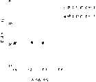
图9是表示对于例7中信号的载波电平变化的图。FIG. 9 is a graph showing changes in the carrier level for the signal in Example 7. FIG.
在本发明中作记录介质的衬底可以是玻璃,塑料(例如聚碳酸酯,聚烯烃)或形成有公知照相排版树脂膜的玻璃中的任一种。The substrate used as the recording medium in the present invention may be any of glass, plastic (such as polycarbonate, polyolefin) or glass formed with a known photosetting resin film.
为了在衬底上形成精细的导槽,利用注射成型将一个Ni压模上的凸纹形状转移到衬底上。To form fine channels on the substrate, injection molding was used to transfer the relief shape from a Ni stamper to the substrate.
压模上的凸纹形状是利用激光束刻感光性树脂形成的。通常使用波长为468nm的Ar激光作为刻切的激光束光源来形成细槽。此外,利用对激光束聚焦镜的开口设置掩膜,或使用例如,He-Cd激光(波长:441nm)或Kr激光(波长:407nm)来形成细槽。The relief shape on the stamper is formed by engraving photosensitive resin with a laser beam. Generally, an Ar laser with a wavelength of 468 nm is used as a laser beam source for scribing to form fine grooves. Further, fine grooves are formed by setting a mask to the opening of the laser beam focusing mirror, or using, for example, He-Cd laser (wavelength: 441 nm) or Kr laser (wavelength: 407 nm).
在迄今使用的具有宽槽宽的衬底的情况下,有时必须振动切刻的激光束,但是形成本发明中导槽时无需这样,因此刻槽是很方便的。In the case of a substrate having a wide groove width hitherto used, it is sometimes necessary to vibrate the laser beam for cutting, but this is not required when forming the guide grooves in the present invention, so the cutting is convenient.
本发明的多层结构的相变介质表示在图1中。The phase change medium of the multilayer structure of the present invention is shown in FIG. 1 .
必须各设置一个用于保护衬底(1)及记录层(3)的保护层(2,4)。如果要求使用的保护层(2,4)具有优异的热阻,并能提供防止衬底热变形的功能及具有可衬底良好的粘接性,则可使用聚碳酸酯树脂衬底,它普遍地在现在用作光盘衬底。A protective layer (2, 4) must each be provided for protecting the substrate (1) and the recording layer (3). If the protective layer (2, 4) required to be used has excellent thermal resistance, and can provide the function of preventing thermal deformation of the substrate and has good adhesion to the substrate, a polycarbonate resin substrate can be used, which is commonly used Ground is now used as a disc substrate.
在本发明中使用的保护层最好是由一种介质材料构成的。The protective layer used in the present invention is preferably composed of a dielectric material.
在本发明中使用的介电材料可能有各种组合,并且它们是考虑到例如绕射率、热导率、化学稳定性、机械强度及粘接力来确定的。Dielectric materials used in the present invention may have various combinations, and they are determined in consideration of, for example, diffraction index, thermal conductivity, chemical stability, mechanical strength, and adhesive force.
通常为氧化物、硫化物、氮化物及碳化物,例如为Ca,Sr,Y,La,Ce,Ho,Er,Yb,Ti,Er,Hf,V,Nb,Ta,En,Al,Si,Ge及Pb的氧化物、硫化物、氮化物及碳化物,及Ca,Mg和Li的氟化物,及其中构成金属氧化物的一部分氧被S或Se取代的化合物均可被使用。Usually oxides, sulfides, nitrides and carbides, such as Ca, Sr, Y, La, Ce, Ho, Er, Yb, Ti, Er, Hf, V, Nb, Ta, En, Al, Si, Oxides, sulfides, nitrides, and carbides of Ge and Pb, and fluorides of Ca, Mg, and Li, and compounds in which a part of oxygen constituting metal oxides is replaced by S or Se can be used.
使用由包含至少ZnS及ZnSe中一种的及至少一种上述化合物的混合物构成的膜可获得有利的重复改写性能及时间上的稳定性。Using a film composed of a mixture containing at least one of ZnS and ZnSe and at least one of the above-mentioned compounds can achieve favorable repeated rewriting performance and stability over time.
在此情况下,金属化合物的含量如果为从3%至6mol%,最好为5至40mol%,则记录盘的存放稳定性特别优异。作为金属化合物可将SiO2及Y2O3作为范例。In this case, if the content of the metal compound is from 3 to 6 mol%, preferably 5 to 40 mol%, the storage stability of the recording disc is particularly excellent. SiO2 and Y2 O3 are exemplified as metal compounds.
保护层的厚度优选在从10至500nm的范围内。The thickness of the protective layer is preferably in the range from 10 to 500 nm.
通常,如果保护层的厚度小于10nm,则防止衬底或记录膜变形的效果就不足。另一方面,在使用塑料衬底的情况下,如果层厚超过500nm,保护层本身中的内部应力或该层与衬底之间的弹性差异将会引起破裂。In general, if the thickness of the protective layer is less than 10 nm, the effect of preventing deformation of the substrate or recording film is insufficient. On the other hand, in the case of using a plastic substrate, if the layer thickness exceeds 500 nm, internal stress in the protective layer itself or a difference in elasticity between the layer and the substrate will cause cracks.
在本发明中,为了改善记录灵敏度,记录层及反射层之间的保护层的厚度最好不小于100nm及不大于500nm。In the present invention, in order to improve the recording sensitivity, the thickness of the protective layer between the recording layer and the reflective layer is preferably not less than 100 nm and not more than 500 nm.
但是,另一方面,为了扩展记录功率范围以便减少重复改写的损坏,甚至是使记录灵敏度牺牲到一定程度,最好厚度为从10至30nm。这将使记录层的热快速地散到上反射层,它能有利于非晶标记的形成,并减少由热聚焦产生的损坏。However, on the other hand, in order to extend the recording power range so as to reduce the damage of repeated overwriting, even to sacrifice the recording sensitivity to a certain extent, the thickness is preferably from 10 to 30 nm. This will quickly dissipate the heat of the recording layer to the upper reflective layer, which can facilitate the formation of amorphous marks and reduce damage caused by thermal focusing.
当使用GeSbTe基材料,GeSnTe基材料,AgInSbTe基材料等作相变光记录层时,为了改善晶化速率、易于获得非晶志、晶粒尺寸及存放稳定度,可以加入Sn,In,Ge,Pb,As,Se,Si,Bi,Au,Ti,Cu,Ag,Pt,Pd,Co,Ni,V,Nb,Ta等。When GeSbTe-based materials, GeSnTe-based materials, AgInSbTe-based materials, etc. are used as phase-change optical recording layers, Sn, In, Ge, Pb, As, Se, Si, Bi, Au, Ti, Cu, Ag, Pt, Pd, Co, Ni, V, Nb, Ta, etc.
其厚度通常选择在从10nm至100nm的范围中,优选为从10nm到50nm,更可取的是从15nm到25nm的范围中。如果记录层的厚度小于10nm,则不能获得足够的光对比度,或者即使获得了,也不能实际应用,因为其厚度依赖性大。考虑到在重复改写中它的耐光性,GeSbTb基材料的记录层有厚度为15至25nm尤为可取。Its thickness is usually selected in the range from 10 nm to 100 nm, preferably from 10 nm to 50 nm, more preferably in the range from 15 nm to 25 nm. If the thickness of the recording layer is less than 10 nm, sufficient optical contrast cannot be obtained, or even if obtained, it cannot be practically used because of its large thickness dependence. It is particularly preferable that the recording layer of the GeSbTb-based material has a thickness of 15 to 25 nm in consideration of its light resistance in repeated overwriting.
另一方面,如果厚度超过100nm,将会趋于形成破裂。On the other hand, if the thickness exceeds 100 nm, cracks tend to form.
记录层(3)是设置成被衬底(1)上的保护层(2,4)夹着,此外,一个反射层(5),若有必要,一个紫外线自愈树脂层(保护膜(6))或类似层被设置在记录层上。The recording layer (3) is arranged to be sandwiched by the protective layer (2, 4) on the substrate (1), in addition, a reflective layer (5), if necessary, an ultraviolet self-healing resin layer (protective film (6) )) or the like is provided on the recording layer.
作为反射膜,可使用主要由Al,Au或Ag构成的金属材料,或包含Ta,Ti,Cr,Si,Mg,Mn及Sc的金属材料。As the reflective film, a metallic material mainly composed of Al, Au, or Ag, or a metallic material containing Ta, Ti, Cr, Si, Mg, Mn, and Sc can be used.
特别是,考虑到记录灵敏度及稳定性,最好用Al及Ti的Al及Ta的合金。In particular, an alloy of Al and Ti, which is Al and Ta, is preferably used in consideration of recording sensitivity and stability.
Ti或Ta的含量最好为从0.5at%(原子百分比)到3.5at%,此时盘的反射率损失可减少,并且它可作为适中的散热层。The content of Ti or Ta is preferably from 0.5 at% (atomic percent) to 3.5 at%, at which point the reflectivity loss of the disk can be reduced, and it can serve as a moderate heat dissipation layer.
记录层、保护层及反射层例如可用溅射形成。膜的形成最好使用列式排列的装置来进行,在同一真空室中设置了用于记录层有靶,用于保护层的靶,及如有必要,用于反射层材料的靶,以便每层之间的氧化或污染。从生产率考虑这也是极佳的。The recording layer, protective layer and reflective layer can be formed by sputtering, for example. The film formation is preferably carried out using an apparatus arranged in an array in which a target for the recording layer, a target for the protective layer, and, if necessary, a target for the reflective layer material are set in the same vacuum chamber so that each Oxidation or contamination between layers. This is also excellent in terms of productivity.
由与保护层(2,4)相同的材料构成的保护膜(6)有时可设置在反射膜(5)上,其厚度从10nm到500nm,以便改善抗擦伤及抗潮湿性能。作为保护膜(6),最好利用旋转喷涂提供厚度约0.5至100μm的热愈或紫外线自愈树脂。A protective film (6) made of the same material as the protective layers (2, 4) may sometimes be provided on the reflective film (5) with a thickness ranging from 10 nm to 500 nm in order to improve scratch resistance and moisture resistance. As the protective film (6), it is preferable to provide a heat-healing or ultraviolet self-healing resin with a thickness of about 0.5 to 100 μm by spin spraying.
为了对本发明的光盘进行记录、删除及读出,使用了被一物镜聚焦的激光束,并从旋转光盘的衬底测照射。For recording, erasing and reading out of the optical disc of the present invention, a laser beam focused by an objective lens is used and irradiated from the substrate side of the rotating optical disc.
在记录及删除时,将一个脉冲调制的激光束照射在旋转光盘上,以使记录层相变成两种可逆状态,即一种晶体化状态或一种非晶状态,由此达到删除状态或记录状态(未记录状态)。When recording and erasing, a pulse-modulated laser beam is irradiated on the rotating disc, so that the recording layer phase changes into two reversible states, that is, a crystallized state or an amorphous state, thereby achieving the erasing state or Logging status (not logging status).
在此情况下,在记录前存在的标记可以在记录的同时利用改写被删除掉。In this case, the mark existing before recording can be deleted by overwriting at the same time as recording.
如图2所示,对上述相变介质的改写是利用对聚焦激光束的调制来进行的。例如,GeSbTe基或AgInSbTe基的相变介质在初始阶段及被删除状态处于晶化状态,而记录坑点的非晶态。在图2中,在改写前(A)的晶化状态(删除状态)中的部分通过激光束功率的照射转变成了改写后(B)的非晶坑(7),在改写前(A)的非晶坑(7)转变成了改写后(B)的删除状态。As shown in FIG. 2, the rewriting of the above-mentioned phase change medium is performed by modulation of a focused laser beam. For example, GeSbTe-based or AgInSbTe-based phase change media are in the crystallized state at the initial stage and the deleted state, while the recording pits are in the amorphous state. In Fig. 2, the part in the crystalline state (deletion state) before rewriting (A) is transformed into an amorphous pit (7) after rewriting (B) by irradiation of laser beam power, and before rewriting (A) The amorphous pits (7) of are transformed into the deleted state after rewriting (B).
记录层被处于至少高于熔点的温度的记录功率(Pw)熔化便形成非晶标记,而记录层的温度由偏置功率(Pb)提供到不高于熔点的温度可晶化形成删除状态。The recording layer is melted by the recording power (Pw) at a temperature at least higher than the melting point to form an amorphous mark, and the temperature of the recording layer is provided by the bias power (Pb) to a temperature not higher than the melting point to crystallize and form an erased state.
在InSbTe基材料中,删除功率(Pb)设得低于(Pw),但也可使用记录层的温度升高到不低于熔点的熔化删除。In the InSbTe-based material, the erasing power (Pb) is set lower than (Pw), but melting erasure in which the temperature of the recording layer is raised to not lower than the melting point may also be used.
在读出时,使用其功率低于记录及删除时激光功率的激光束照射旋转光盘。在此情况下,在读出前一时刻的记录层相态将不会改变。At the time of reading, the rotating disc is irradiated with a laser beam whose power is lower than that of the laser at the time of recording and erasing. In this case, the phase state of the recording layer at the moment before readout will not change.
读出是利用光检测器检测反射光的强度变化以判断出记录状态或非记录状态来实现的。Readout is realized by using a photodetector to detect the change in the intensity of reflected light to judge whether it is a recording state or a non-recording state.
在根据本发明的光盘中,如果在无论是脊上还是槽中重复改写多次,可防止删除率的显著下降,及可高质量地获得读出信号,并且对于脊及槽两者的记录标记很少不稳定。In the optical disc according to the present invention, if rewriting is repeated many times in either the land or the groove, a significant decrease in the erasure rate can be prevented, and a read signal can be obtained with high quality, and recording marks for both the land and the groove can be prevented. Rarely unstable.
如果考虑重复改写特性,使醴宽窄而脊宽加大而利用格量变宽的优点来确定出槽宽窄于脊宽,则记录密度可作到等于或大于具有相同脊宽及槽宽的现有L&G记录光盘的记录密度,在后者中轨距以有相同程度的降低。If the characteristics of repeated rewriting are considered, the width of the ribs is narrow and the width of the ridges is increased, and the advantage of widening the grid volume is used to determine that the groove width is narrower than the ridge width, then the recording density can be equal to or greater than that of the existing L&G with the same ridge width and groove width. The recording density of the recording disc, in which the track pitch decreases to the same extent.
图3是表示根据本发明的光盘一部分的放大透视概图。在光盘衬底上预先形成了脊(8)及槽(9),其中每个脊及槽的宽度是以放大比例表示的,与槽宽(GW)相比,脊宽(LW)在一定范围上作得较宽。Fig. 3 is an enlarged perspective schematic view showing a part of an optical disc according to the present invention. Ridges (8) and grooves (9) are pre-formed on the optical disc substrate, wherein the width of each ridge and groove is expressed in an enlarged scale. Compared with the groove width (GW), the ridge width (LW) is within a certain range Make it wider.
如图1中所示的多层结构中的记录层(2)由介电层或类似层保护,但是为了易于理解此图除记录层(2)外的其它层被省略了。The recording layer (2) in the multilayer structure as shown in Fig. 1 is protected by a dielectric layer or the like, but layers other than the recording layer (2) are omitted in this figure for ease of understanding.
图3表示读出光束照射到L&G光盘的脊(8)上的未记录区域的一个例子。Fig. 3 shows an example of the unrecorded area on the land (8) of the L&G disc irradiated with the reading beam.
使用一个物镜或类似物聚焦的激光束(10)从衬底(1)侧照射到盘上,用于进行记录、删除及读出。A laser beam (10) focused using an objective lens or the like is irradiated onto the disc from the substrate (1) side for recording, erasing and reading.
因为聚光光束(10)是从衬底侧照射的,因此它是从图纸的反面进入至被反射的。因而,从光源看过来,脊部分(8)是凹的,而槽部分(9)是凸的。Since the concentrated light beam (10) is irradiated from the substrate side, it enters from the opposite side of the drawing to be reflected. Thus, seen from the light source, the ridge portion (8) is concave and the groove portion (9) is convex.
脊(8)及槽(9)之间的平面差距(d)可以为任何值,只要该值在λ/7n至λ/5n的范围中,其中λ是聚焦光束(10)的波长,而n是衬底(1)的绕射率。The plane difference (d) between the ridge (8) and the groove (9) can be any value as long as the value is in the range of λ/7n to λ/5n, where λ is the wavelength of the focused light beam (10), and n is the diffraction index of the substrate (1).
这是因为如日本"应用物理"杂志第32卷(1993年)第5324-5328行中所描述的,当槽深在从λ7n至λ/5n(λ:读出光波长,n:衬底绕射率)时来自邻轨的串音下降了。这篇报道是基于一个假设:(脊宽)=(槽宽),而是为提出本发明。但是,本发明中将槽深确定为λ/7n至λ/5n是有效的。当本发明人对于本发明中的几何结构:GW<LW作出与上述报道中类似的计算时,发现在λ/7n<d<λ/5n,尤其是对于非对称的L&G几何结构在λ/7n<d<λ/5n时,串音得到其最小值。This is because, as described in the Japanese "Applied Physics" Journal, Vol. 32 (1993), lines 5324-5328, when the groove depth is from λ7n to λ/5n (λ: readout light wavelength, n: substrate winding crosstalk from adjacent tracks is reduced. This report is based on an assumption: (ridge width) = (groove width), but to propose the present invention. However, it is effective in the present invention to determine the groove depth to be λ/7n to λ/5n. When the present inventor made a calculation similar to that in the above report for the geometric structure in the present invention: GW<LW, it was found that λ/7n<d<λ/5n, especially for the asymmetrical L&G geometric structure at λ/7n When <d<λ/5n, the crosstalk gets its minimum value.
在本发明中,脊宽被确定在从0.62(λ/NA)至0.80(λ/NA)的范围中,其中λ表示照射光束的波长,而NA是物镜的数字光圈。In the present invention, the ridge width is determined in the range from 0.62(λ/NA) to 0.80(λ/NA), where λ represents the wavelength of the irradiation beam and NA is the numerical aperture of the objective lens.
如果脊宽比上述范围窄,则在脊上重复改写记录标记的情况下,预录的标记将会明显地被留下而未被删除,使记录标记的稳定性变差。这在一次性类型的相变介质中不会引起问题,但对可重写型光盘带来了问题。If the land width is narrower than the above range, in the case of repeated rewriting of the recorded marks on the lands, the pre-recorded marks will be conspicuously left without being erased, deteriorating the stability of the recorded marks. This does not cause a problem in disposable type phase change media, but it poses a problem for rewritable type optical discs.
如果脊宽在上述范围中,则在重复改写的情况下不会有预录标记的删除剩余或是使记录标记的稳定性明显变坏,并可保持与槽中的记录相同的特性。If the land width is within the above range, there will be no residual deletion of pre-recorded marks or a significant deterioration in the stability of recorded marks in the case of repeated overwriting, and the same characteristics as recording in grooves can be maintained.
如果脊宽大于上述范围,对于脊的重复改写特性不会有特殊问题,并能获得满意的特性。但是脊宽不必要的加大会减少记录密度,从高密度记录来考虑没有好处。If the ridge width is larger than the above range, there is no particular problem with regard to the repetitive overwriting characteristics of the ridges, and satisfactory characteristics can be obtained. However, an unnecessary increase in the ridge width will reduce the recording density, which is not beneficial in terms of high-density recording.
现在来描述测量槽宽及槽深的方法。该测量是利用从未设槽的衬底侧照射一种He-Ne激光束(波长:633nm),及测量相应于由衬底槽绕射的零次光强度(I0),一次光强度(I1)及二次光强度(I2)的发射光及绕射光的角度。The method of measuring the groove width and groove depth will now be described. The measurement is to irradiate a He-Ne laser beam (wavelength: 633nm) from the substrate side without grooves, and measure the zero-order light intensity (I0) and the primary light intensity (I0) corresponding to the diffraction by the substrate groove.1 ) and the angle of the emitted light and the diffracted light of the secondary light intensity (I2 ).
假定槽距为(P),槽宽为(W),槽深为(d),激光波长为λ及0次反射光及1次绕射光之间的角度为θ,则可计算槽宽及槽深,因为在矩形槽的情况下建立了以下的关系式:Assuming that the groove pitch is (P), the groove width is (W), the groove depth is (d), the laser wavelength is λ, and the angle between the 0th reflected light and the 1st diffracted light is θ, the groove width and groove width can be calculated. deep, since the following relation is established in the case of rectangular slots:
I2/I1=cos2(π/ε)I2 /I1 = cos2 (π/ε)
I1/I0={2sin2(πε)(1-cosδ}/[π2{1-2ε(1-ε)(1I1 /I0 ={2sin2 (πε)(1-cosδ}/[π2 {1-2ε(1-ε)(1
-cos δ)}]-cos δ)}]
ε=W/P,δ=2-(n-1)πd/λε=W/P,δ=2-(n-1)πd/λ
(n:衬底的绕射率)(n: diffraction rate of the substrate)
p=λ/sinθp=λ/sinθ
虽然槽的真实形状不完全是矩形,但用上述方法单义地确定出的槽宽及槽深的值将作为本发明的槽形状。Although the real shape of the groove is not completely rectangular, the values of the groove width and groove depth determined unambiguously by the above-mentioned method will be used as the groove shape of the present invention.
因而,对于槽形状偏离了本发明中的完全矩形形状的情况,它也是可适用的。Thus, it is also applicable to cases where the groove shape deviates from the perfectly rectangular shape in the present invention.
此外,可靠的作法是利用预先对衬底盘的表面及横截面进行观察,例如使用SEM,STM(AFM)作观察,描出槽形状尺寸,然后参照它利用上述测量及计算由精确确定的槽宽及槽深来确定其形状。另外,当槽距小于λ的二倍(2λ)时,上述光绕射法不适用。对此情况,仅可采用SEM或STM(AFM)分析。In addition, a reliable method is to observe the surface and cross section of the substrate disk in advance, such as using SEM, STM (AFM) for observation, to trace the shape and size of the groove, and then refer to it to use the above measurement and calculation to accurately determine the groove width and The groove depth determines its shape. In addition, when the groove pitch is smaller than twice (2λ) of λ, the above-mentioned light diffraction method is not applicable. In this case, only SEM or STM (AFM) analysis can be used.
在本发明中,因为脊宽大于槽宽,在脊上的记录标记宽度可能大于槽中记录标记的宽度,其结果是在脊上读出信号的CN比(载波或噪音之比)的幅度大于槽中的该种信号幅度,并有时会引起它们之间的信号质量差别。In the present invention, since the width of the land is larger than the width of the groove, the width of the recording mark on the land may be larger than the width of the recording mark in the groove, as a result, the amplitude of the CN ratio (carrier or noise ratio) of the read signal is larger than The amplitude of such signals in the slots, and sometimes cause differences in signal quality between them.
在这种情况下,有效的方式是选择层的结构,以使得在槽中的读出信号幅度或CN比作得比在脊上的大。In this case, it is effective to choose the structure of the layer such that the readout signal amplitude or CN ratio is made larger in the groove than in the land.
为了导致该目标,可建议,在记录前后读出光的反射光量的变化在槽中要作得大于脊上。In order to lead to this goal, it may be proposed that the change in the reflected light quantity of readout light before and after recording is made larger in grooves than in lands.
作为一种专门的对付措施,有效的作法是对记录前后的反射光的相位差加以注意,并将该相位差限定在对槽上记录有利的范围中。As a special countermeasure, it is effective to pay attention to the phase difference of reflected light before and after recording, and to limit the phase difference to a range favorable for on-groove recording.
利用满足下列条件(1)或条件(2),可使槽记录中的读出信号幅值改善并在脊记录及槽记录两者中获得相同质量的信号幅值。By satisfying the following condition (1) or condition (2), it is possible to improve the readout signal amplitude in groove recording and obtain the same quality signal amplitude in both land recording and groove recording.
条件(1):Condition (1):
在本发明的光记录介质中,如果已记录区域(R2)中的反射率低于未记录区(R1)中的反射率,来自未记录区的反射光与来自记录区的反射光之间的相位差由下式(4)表示:In the optical recording medium of the present invention, if the reflectance in the recorded region (R2 ) is lower than that in the unrecorded region (R1 ), the difference between the reflected light from the unrecorded region and the reflected light from the recorded region The phase difference between is expressed by the following formula (4):
-π<α<0 (4)-π<α<0 (4)
其中的α=(未记录区反射光的相位)-(已记录区反射光的相位)Among them, α=(phase of reflected light in unrecorded area)-(phase of reflected light in recorded area)
也就是说,来自未记录区的反射光的相位比来自记录区的反射光的相位有一个范围在0至π之间的延迟。That is, the phase of the reflected light from the unrecorded area has a retardation in the range of 0 to π compared to the phase of the reflected light from the recorded area.
条件(2):Condition (2):
在本发明的光记录介质中,如果已记录区中的反射率高于未记录区中的反射率,来自未记录区的反射光与来自记录区的反射光之间的相位差由下式(6)表示:In the optical recording medium of the present invention, if the reflectance in the recorded area is higher than that in the unrecorded area, the phase difference between the reflected light from the unrecorded area and the reflected light from the recorded area is given by the following formula ( 6) means:
π<α<π (6) (6)
其中的α=(未记录区反射光的相位)-(已记录区反射的光的相Among them, α=(the phase of the reflected light in the unrecorded area)-(the phase of the reflected light in the recorded area
位)bit)
也就是说,来自未记录区的反射光的相位比未自己记录区的反射光的相位有一个范围在0至π之间的超前。That is to say, the phase of the reflected light from the unrecorded area is ahead of the phase of the reflected light from the unrecorded area by a range from 0 to π.
另外,最好是把槽上的记录标记的读出信号中相位在以下范围内的那部分幅值增大:In addition, it is preferable to increase the amplitude of the portion of the read signal of the recording mark on the groove whose phase is within the following range:
对条件(1)的情况下,In the case of condition (1),
-(3/4)π<α<-(1/4)π,或是-(3/4)π<α<-(1/4)π, or
在条件(2)的情况下,In the case of condition (2),
(1/4)π<α<(3/4)π(1/4)π<α<(3/4)π
为了设计上满足上述条件的盘,在相位改变的前、后需要精确地调整反射光的相位差。In order to design a disc satisfying the above conditions, it is necessary to precisely adjust the phase difference of reflected light before and after the phase change.
反射光在相位改变前、后的相位改变可以用激光干扰显微镜等手段来实际测量,也可以采用盘的各层的光学常数和厚度通过计算来确定。The phase change of the reflected light before and after the phase change can be actually measured by means of laser interference microscopy, or can be determined by calculation using the optical constants and thicknesses of each layer of the disk.
计算方法可以参见"Base and Method for Spectroscopy(作者为Keiei Kudo,由Ohm Co.,发表1985,Chapter3)。The calculation method can be found in "Base and Method for Spectroscopy (authored by Keiei Kudo, published by Ohm Co., 1985, Chapter 3).
各层的光学常数可以通过预先制做单层膜的方式来获得,例如用溅射方法,然后用椭率计算仪器测量。The optical constants of each layer can be obtained by prefabricating a single-layer film, for example, by sputtering, and then measured by an ellipsometric calculation instrument.
在脊部(land)记录或槽记录的记录方式前、后的反射比改变和相位差可以分别用日本专利申请公开5-128589号中的所述的计算公式表示。The change in reflectance and the phase difference before and after the recording mode of land recording or groove recording can be expressed by calculation formulas described in Japanese Patent Application Laid-Open No. 5-128589, respectively.
然而,日本专利申请公开5-128589号中没有描述采用脊和槽二者作为记录区的技术。However, there is no description in Japanese Patent Application Laid-Open No. 5-128589 that uses both lands and grooves as recording areas.
另外,完全没有考虑脊与槽之间的宽度的限制,在本发明中采用的宽度限制是为了改善槽内的CN比,槽的宽度比脊的宽度相对较窄。In addition, the limitation of the width between the land and the groove is not considered at all. The width limitation adopted in the present invention is to improve the CN ratio in the groove, and the width of the groove is relatively narrower than that of the land.
本发明中的L&G光盘是一种可写的光信息记录介质,但也可以用做只能写入一次的一次写入型记录介质。The L&G optical disc in the present invention is a writable optical information recording medium, but it can also be used as a write-once recording medium that can only be written once.
可以通过驱动器在盘上记录一种写入抑制信号,从而防止二次的记录删除。A write-inhibit signal can be recorded on the disc by the drive to prevent secondary recording erasure.
这种盘可以做为单面盘使用,也可以把两个相对的盘附着在基片的两个表面上,从而使容易加倍。This disk can be used as a single-sided disk, or two opposing disks can be attached to both surfaces of the substrate for easy doubling.
这是一个重要的特征,磁-光型的盘是无法实现这种方式的,在磁-光盘的激光照射面背面需要有磁性。This is an important feature, which cannot be achieved with magneto-optical discs, and magnetism is required on the back of the laser-irradiated surface of the magneto-optical disc.
日本专利申请公开6-338064号中公开了一种对槽的深度和宽度的限制,但是,其基本条件是槽与脊的宽度大体相等,这一点是与本发明不同的。另外,该申请没有限定脊的宽度要大于槽的宽度。Japanese Patent Application Laid-Open No. 6-338064 discloses a restriction on the depth and width of the grooves, but the basic condition is that the widths of the grooves and lands are substantially equal, which is different from the present invention. Additionally, the application does not limit the width of the ridges to be greater than the width of the grooves.
在缩小槽和脊的宽度,使槽宽不大于0.35(λ/NA0的情况下在槽内进行记录,若利用上述的相位差增大槽内的信号,就可以获得足够的信号强度。Reduce the width of the groove and the land, and record in the groove under the condition that the groove width is not more than 0.35 (λ/NA0. If the signal in the groove is increased by using the above-mentioned phase difference, sufficient signal strength can be obtained.
此外,从重复记录特性的角度来看,窄槽是有益的,这是相变型光盘的一个重要问题。Furthermore, narrow grooves are beneficial from the viewpoint of repetitive recording characteristics, which is an important issue in phase-change type optical discs.
目前还不能充分地解释利用窄槽时的重复记录特性为什么会这样好,可能是因为槽限制了记录层材料的转移和变形。It is not yet fully explained why the repetitive recording characteristics are so good when using narrow grooves, probably because the grooves limit the transfer and deformation of the recording layer material.
槽的宽度应该变窄,但是,如果槽宽变得太窄了,轨迹误差信号的强度就会不足。另外,在槽的底部缺少平面部分,这样会使信号强度下降。此外,在L&G记录中,记录标记的宽度最好是不超过槽的宽度。The groove width should be narrowed, however, if the groove width becomes too narrow, the strength of the tracking error signal will be insufficient. Also, there is a lack of flats at the bottom of the slot, which can degrade signal strength. Furthermore, in L&G recording, it is preferable that the width of the recording mark does not exceed the width of the groove.
槽的厚度对重复记录特性也有影响。槽如果过浅,重复记录特性就会变坏,轨迹误差信号也会下降。如果槽过深了,槽底的平面部分就会缩小,造成信号强度下降的缺点。The thickness of the groove also has an influence on the repetitive recording characteristics. If the groove is too shallow, the repetitive recording characteristics will deteriorate, and the tracking error signal will also drop. If the groove is too deep, the plane portion of the bottom of the groove will shrink, resulting in the disadvantage of a decrease in signal strength.
因此,槽宽可以从0.05(λ/NA)至0.5(λ/NA),最好是从0.25(λ/NA)到0.35(λ/NA),其中的λ是记录激光的波长,而NA是物镜的数字光圈。Therefore, the groove width can be from 0.05(λ/NA) to 0.5(λ/NA), preferably from 0.25(λ/NA) to 0.35(λ/NA), where λ is the wavelength of the recording laser and NA is The numerical aperture of the objective lens.
例如使用物镜的条件是波长为780nm,NA为0.55,槽宽可以是0.21至0.51μm,最好是0.35至0.50μm。另外,从槽成形处理的限制来考虑,对槽宽的较低限制为0.1μm。For example, the conditions for using the objective lens are that the wavelength is 780 nm, the NA is 0.55, and the groove width may be 0.21 to 0.51 μm, preferably 0.35 to 0.50 μm. In addition, the lower limit on the groove width is 0.1 μm in consideration of the limitation of the groove forming process.
槽的深度最好是40至80nm,如果考虑到重写期间的耐久性问题,从45至70nm则更好。The depth of the groove is preferably 40 to 80 nm, more preferably 45 to 70 nm in consideration of durability during rewriting.
更进一步,本发明的效果随着全于记录层和反射层之间的介电保护层的厚度的增大而变得更加显著,并且这种层结构具有较好的记录灵敏度,由于有了上面的厚保护层,抑制了热扩散,从而大大改善了写入录敏度。Further, the effect of the present invention becomes more remarkable as the thickness of the dielectric protective layer between the recording layer and the reflective layer increases, and this layer structure has better recording sensitivity, due to the above The thick protective layer suppresses thermal diffusion, thus greatly improving the write recording sensitivity.
对相变型光盘来说,需要把温度升高到普通记录膜的熔点以上,并且其工作温度比磁-光盘一类的记录介质要高,因此通常会导致灵敏度差的问题。For phase-change optical discs, the temperature needs to be raised above the melting point of ordinary recording films, and its operating temperature is higher than that of magneto-optical discs, which usually leads to poor sensitivity.
特别是当所用的激光波长为了进一步增加密度而缩短时,灵敏度的问题就更重要了,因为很难得到更大功率的激光二极管。Especially when the wavelength of the laser used is shortened to further increase the density, the issue of sensitivity is even more important, because it is difficult to obtain higher power laser diodes.
然而,由于存在采用高灵敏度的层结构会使相变型光盘的重复记录特性进一步变坏的问题,灵敏度差的光盘仍在使用。However, since there is a problem that the repeated recording characteristics of phase-change type optical discs are further deteriorated by adopting a layer structure with high sensitivity, optical discs with poor sensitivity are still used.
与此相反,采用一种具有较高的写灵敏度和较厚的上部保护层的光盘可以进一步增强本发明的效果,有可能获得一种具有高的写灵敏度以及良好的重复记录特性的相变型光盘。On the contrary, adopting a kind of optical disc with higher write sensitivity and thicker upper protective layer can further enhance the effect of the present invention, and it is possible to obtain a phase change type with high write sensitivity and good repeat recording characteristics CD.
另外,脊宽(LW)和槽宽(GW)最好是备以下的关系:In addition, the land width (LW) and the groove width (GW) preferably have the following relationship:
0.02≤(LW-GW)/PG≤0.3 (8)0.02≤(LW-GW)/PG≤0.3 (8)
其中的LW代表脊宽(μm),GW代表槽宽(μm),而PG代表槽间距(μm)[=GW+LW]。Among them, LW represents the land width (µm), GW represents the groove width (µm), and PG represents the groove pitch (µm) [=GW+LW].
如果脊宽与槽宽之间的差别过大,槽中的信号就会小于脊上的信号,即使是象上述那样,采用了层结构来加强槽中的信号值,仍会导致失去平衡,因此最好是采用一个限制:If the difference between the width of the ridge and the width of the groove is too large, the signal in the groove will be smaller than the signal on the ridge. Even if the layer structure is used to strengthen the signal value in the groove as mentioned above, it will still cause an imbalance, so It is better to use a limit:
(LW-GW)/PG≤0.3 (LW-GW)/PG≤0.3
另一方面,当脊宽大于槽宽时,在记录之前可以特别地在脊上的反射率与槽内的反射率比之间设置一个有意义的差值,它被限定为:On the other hand, when the land width is larger than the groove width, a meaningful difference can be set prior to recording in particular between the ratio of the reflectance on the land to the reflectance inside the groove, which is defined as:
(LW-GW)/PG≥0.02使得按照三束方式的跟踪伺服可以稳定地工作。(LW-GW)/PG≥0.02 makes the tracking servo work stably according to the three-beam method.
另外,便于由伺服系统独立地获得所谓的轨迹跨越信号。实际上,如果脊宽与槽宽接近相等,就无法获得轨迹跨越信号,这样则不可能进行所谓轨迹记数,对轨迹记数的目的是为了找到一个特定的轨迹。尽管还可以采用其他存取方法,采用现有的轨迹记数方法仍具有很大的优点。In addition, it is convenient to obtain so-called track crossing signals independently from the servo system. In fact, if the land width is approximately equal to the groove width, no track crossing signal can be obtained, so that so-called track counting is impossible, the purpose of track counting is to find a specific track. Although other access methods can be used, there are still great advantages to using the existing track counting method.
通过在上述范围内使槽宽小于脊宽,脊和槽之间的读出信号的载波电平可达到基本相同,来自槽部分的反射光与来自脊部分的反射光的差值在采用三束系统的情况下可以有差别。还可以获得良好的轨迹跨越信号。By making the groove width smaller than the land width within the above range, the carrier level of the readout signal between the land and the groove can be substantially the same, and the difference between the reflected light from the groove portion and the reflected light from the land portion can be achieved by using three beams. System conditions can vary. A good trace crossing signal can also be obtained.
因此,在读出信息记录介质时,除了推挽系统之外还可以使用三束系统,用分离的推挽系统作为跟踪系统,而轨迹跨越信号可被用作于对径向移动所通过的轨迹计数。Therefore, when reading out an information recording medium, a three-beam system can be used in addition to a push-pull system, a separate push-pull system can be used as a tracking system, and a track crossing signal can be used as a tracking system for radial movement. count.
在考虑到跟踪伺服特性时,槽深最好是处于λ/10n至λ/5n的范围内,此处假定记录/读出光源的波长为λ,而基片的反射系数为n,在考虑到串音时,最佳的范围是λ/6.5n至λ/5.5n。When considering the tracking servo characteristics, the groove depth is preferably in the range of λ/10n to λ/5n, where it is assumed that the wavelength of the recording/reading light source is λ, and the reflection coefficient of the substrate is n, considering When crosstalking, the best range is λ/6.5n to λ/5.5n.
以下说明本发明用于克服串删现象的特征,这种串删是指相邻轨迹中的信号在重复记录时被删除。在本发明中,限定了一个最小轨迹间距:(LW+GW)/2,用于克服串删现象。The features of the present invention for overcoming the phenomenon of cross erasure, in which signals in adjacent tracks are erased during repeated recording, will be described below. In the present invention, a minimum track spacing is defined: (LW+GW)/2, which is used to overcome the phenomenon of serial erasure.
由于光束点的点直径与λ/NA成正比,允许的最小轨迹间距也应该与λ/NA成正比。Since the spot diameter of the beam spot is proportional to λ/NA, the allowable minimum track pitch should also be proportional to λ/NA.
比例系数可以根据实践来精确地确定。The proportionality factor can be precisely determined according to practice.
根据本发明人的各种实际研究,如果用于L&G记录的槽间距大于1.2(λ/NA),在104次重写之后,C/N比(载波与噪声之比)的下降可以减少到3dB以下,由此所达到的电平实际上没有问题。According to various practical studies by the present inventors, if the groove pitch for L&G recording is greater than1.2 (λ/NA), the drop in C/N ratio (carrier-to-noise ratio) can be reduced to Below 3dB, the levels thus achieved are practically unproblematic.
也就是说,可以根据实验得出结论,由于在L&G记录中实际的记录轨迹间距是槽间距的二分之一,如果使最小记录轨迹间距大于0.6(λ/NA),就可以防止由于串删造成相邻轨迹中的信号劣化。That is to say, it can be concluded from experiments that since the actual recording track pitch in L&G recording is 1/2 of the groove pitch, if the minimum recording track pitch is greater than 0.6(λ/NA), it can prevent the gap due to string deletion. Causes signal degradation in adjacent tracks.
上述的数值0.6在理论上刚好对应通过物镜(11)的一个聚焦光束(12)的光束点的二分之一。The above-mentioned value 0.6 corresponds theoretically to one-half of the beam spot of a focused beam (12) passing through the objective lens (11).
也就是说,聚焦光束(12)具有图4所示的形状,并且由于绕射效应在强度分布中出现一个次尖峰(Sub-peak)(图4中的曲线(13)表示强度分布)。That is, the focused beam (12) has the shape shown in FIG. 4, and a sub-peak (Sub-peak) appears in the intensity distribution due to the diffraction effect (the curve (13) in FIG. 4 represents the intensity distribution).
中心点的直径大约为1.2(λ/NA),这被称为是一个弥散圈(14)。The diameter of the center point is about 1.2(λ/NA), which is called a circle of diffusion (14).
另外,光强度的分布是不均匀的,而光强度达到1/e2(e是自然对数的底)的直径可表示为0.82(λ/NA)。In addition, the distribution of light intensity is not uniform, and the diameter at which the light intensity reaches 1/e2 (e is the base of natural logarithm) can be expressed as 0.82(λ/NA).
由于轨迹(1)的最小间距对应着弥散圈的半径,从物理学的角度可以知道,由于相邻轨迹的温度在作为第一近似值的聚焦激光束点强度分布的根部弱照射光的作用下有所升高,就会造成删现象。Since the minimum spacing of the track (1) corresponds to the radius of the diffuse circle, it can be known from a physical point of view that the temperature of the adjacent tracks has If it is increased, it will cause deletion.
记录层中的热传导对串删现象基本上没有实质影响,这是因为在GeST,AgInSbTe,InSnTe或InSbTe的记录层中的热传导率要比磁-光型的介质低2-3个数量级,诸如GeSbTe,AgInSbTe,InSaTe或InSbTe的这种记录层包含不少于40at%的属于族IIIb,IVb,Vb,VIb中的一种元素或是其混合物(合金)作为主要成份。The heat conduction in the recording layer has basically no substantial effect on the cross-erasing phenomenon, because the thermal conductivity in the recording layer of GeST, AgInSbTe, InSnTe or InSbTe is 2-3 orders of magnitude lower than that of magneto-optical media, such as GeSbTe , AgInSbTe, InSaTe or InSbTe, this recording layer contains not less than 40 at % of an element belonging to groups IIIb, IVb, Vb, VIb or a mixture (alloy) thereof as a main component.
另一个原因还在于这种记录层在记录所需的10至100毫微秒期间基本上是绝热的。Another reason is also that this recording layer is substantially adiabatic during the 10 to 100 nanoseconds required for recording.
因此,上述0.6(λ/NA)所限定的最小轨距实际上是由光束点的直径所确定的,也就是说,仅取决于光束的波长和NA。Therefore, the above-mentioned minimum track pitch defined by 0.6(λ/NA) is actually determined by the diameter of the beam spot, that is, depends only on the wavelength and NA of the beam.
然而,若采用多层结构的记录介质,或是限制记录层的物理性质,还可以在不少于10000次重写的条件下进一步减少串删,尽管其作用有限。However, if a recording medium with a multi-layer structure is used, or the physical properties of the recording layer are limited, the serial erasure can be further reduced under the condition of not less than 10,000 overwrites, although its effect is limited.
目前所知的可能在结晶态/非结晶态之间可逆变化的合金记录层成分的熔点(Tm)通常低于700℃,并且其结晶温度(Tg)不低于150℃,这当然还要取决于记录层的熔点或结晶温度。The melting point (Tm) of the currently known alloy recording layer composition that may reversibly change between crystalline/amorphous states is usually lower than 700°C, and its crystallization temperature (Tg) is not lower than 150°C, which of course depends on At the melting point or crystallization temperature of the recording layer.
实际上,对于具有接近Ge1Sb2Te4或Ge2Sb2Te5成分的层状来说,其熔点600至620℃,结晶温度为150至170℃。Actually, for a layer having a composition close to Ge1 Sb2 Te4 or Ge2 Sb2 Te5 , the melting point is 600 to 620°C, and the crystallization temperature is 150 to 170°C.
另外,在Ag0.11In0.11Te0.20Sb0.55的成分中,熔点约为550℃,结晶温度约为230℃。In addition, in the composition of Ag0.11 In0.11 Te0.20 Sb0.55 , the melting point is about 550°C, and the crystallization temperature is about 230°C.
如果Tg低于150℃,非晶态的稳定性就变差,容易出现串删。If the Tg is lower than 150° C., the stability of the amorphous state becomes poor, and cross deletion is likely to occur.
此外,如果Tm超过700℃,记录时所需的照射能量就要增大,也容易对相邻轨迹造成串删。In addition, if the Tm exceeds 700°C, the irradiation energy required for recording will increase, and cross-cutting of adjacent tracks will easily occur.
从层结构来看,如果记录层厚度超过30nm,由于记录灵敏度下降并且热量容易散到相邻的轨迹,也容易发生串删。From the perspective of the layer structure, if the recording layer thickness exceeds 30nm, cross-erasing is also likely to occur because the recording sensitivity is lowered and heat is easily dissipated to adjacent tracks.
还有,由于最小轨距的限制是由记录轨距和聚焦光束半径来确定的,其有效性不仅适用于L&G记录,同样适用于在预设坑上的采样伺服记录,以及象通常那样在设有槽的脊上记录。Also, since the minimum track pitch is limited by the recording track pitch and the radius of the focused beam, its effectiveness applies not only to L&G recording, but also to sampling servo recording on preset pits, and as usual in setting Recorded on ridges with grooves.
然而,由于在L&G记录时为了减少串音而为槽深设定为λ/5n至λ/7n(n:衬底的绕射率数),最好的情况是将这种措施与本发明相结合。However, since the groove depth is set to λ/5n to λ/7n (n: the diffraction index number of the substrate) for the purpose of reducing crosstalk at the time of L&G recording, it is best to use this measure in accordance with the present invention. combined.
另外,如上所述可以在GW<LW的条件下把条件:(LW+GW)/2>0.6(λ/NA)用于L&G记录,在条件:GW≌LW的情况下也可以这样做。如果在条件:GW<LW的场合采用上述条件,就可以有效地克服串删,同时又相对于GW≌LW的情况下改善实际的轨距。In addition, the condition: (LW+GW)/2>0.6(λ/NA) can be used for L&G recording under the condition of GW<LW as described above, and the same can be done under the condition of GW≌LW. If the above conditions are adopted in the condition: GW<LW, the string deletion can be effectively overcome, and the actual gauge distance can be improved relative to the situation of GW≌LW.
在窄间距的条件下使用槽或脊之一进行记录时,已知的最佳槽深为λ/8n,以便用推挽方式获得伺服信号。When recording is performed using either groove or land at a narrow pitch, the optimum groove depth is known to be λ/8n in order to obtain a servo signal in a push-pull manner.
另外,在采样伺服记录方式下,伺服坑(Servo-pit)的深度最佳值已知为λ/4n,最好是将这种条件与本发明相结合。In addition, in the sampling servo recording method, the optimum value of the depth of the servo pit (Servo-pit) is known as λ/4n, and it is preferable to combine this condition with the present invention.
如图1所示的多层结构是形成在透明树脂或玻璃衬底上的,这种衬底知合用于记录和读出的光学应用。The multilayer structure shown in FIG. 1 is formed on a transparent resin or glass substrate suitable for optical applications of recording and reading.
通常的树脂衬底诸如由聚碳酸酯或聚烯烃构成的衬底比较便宜,并且通过常用的挤压成型方法可以形成精细的不均匀结构。A general resin substrate such as a substrate composed of polycarbonate or polyolefin is relatively inexpensive, and a fine uneven structure can be formed by a common extrusion molding method.
对于聚烯烃衬底,可以采用目前商用的Zeonex(由NipponZeon Co.,Ltd制造),Arton(由Japan Synthetic Rubber Co.,Ltd制造),Apel(由Mitsui Petrochemical Industries,Ltd.制造)。因为这些材料具有小的光测弹性常数,小于400×10-6的垂直双折射率,并且容易实现小于40×10-6的共面双折射率。As the polyolefin substrate, currently commercially available Zeonex (manufactured by NipponZeon Co., Ltd.), Arton (manufactured by Japan Synthetic Rubber Co., Ltd.), Apel (manufactured by Mitsui Petrochemical Industries, Ltd.) can be used. Because these materials have a small photometric elastic constant, a vertical birefringence of less than 400×10-6 , and an in-plane birefringence of less than 40×10-6 is easily achieved.
另一方面,在聚碳酸脂树酯中,由于通常用于光盘的双榍A树脂的平均分子量约为15000,其光测弹性常数很大,采用通常的注射压模方法仅能获得400×10-6至600×10-6的垂直双折射率。On the other hand, among polycarbonate resins, since the average molecular weight of the bisphena resin commonly used for optical discs is about 15,000, its photometric elastic constant is very large, and only 400×10 can be obtained by the usual injection molding method. Vertical birefringence of-6 to 600×10-6 .
小于400×10-6的垂直双折射可以用以下方式获得,即在模制一种聚碳酸酯时分多步改变施加在模腔上的压力,并且在冷却步骤中迅速减少压力。A vertical birefringence of less than 400 x 10-6 can be obtained by varying the pressure applied to the mold cavity in multiple steps when molding a polycarbonate and rapidly reducing the pressure during the cooling step.
另外还可用这样的方式来实现同样具有较低垂直双折射的衬底,即在比玻璃的临界点低20至30℃的温度下进行退火。Substrates that also have a lower vertical birefringence can additionally be achieved by annealing at a
为了把其面双折射降低到4-×10-6以下,最有效的方式是在注射期间通过分散应力来增加用于抑制分子定向的树脂的流动性。In order to reduce its surface birefringence below 4-×10-6 , the most effective way is to increase the fluidity of the resin used to suppress molecular orientation by dispersing stress during injection.
为了这一目的,树脂的分子量应较低,或是把树脂的熔点温度定得较高。For this purpose, the molecular weight of the resin should be low, or the melting temperature of the resin should be set high.
例如,对使用双榍A的聚碳酸脂来说,平均分子量应控制在4,000至20,000的范围内,模制时的树脂温度应定为350℃左右。For example, for polycarbonate using bisphena A, the average molecular weight should be controlled within the range of 4,000 to 20,000, and the resin temperature during molding should be set at about 350°C.
在相变型介质中,平面双折射率的允许范围很大,足以达到小于40×10-6的要求。In phase-change media, the allowable range of plane birefringence is large enough to meet the requirement of less than 40×10-6 .
然而,如果不小于40×10-6,就会造成不应有的偏差,或是需要增强光源的激光束。However, if it is not less than 40×10-6 , undue deviation is caused, or it is necessary to intensify the laser beam of the light source.
另一方面,由受到垂直双折射控制的散光造成的影响出现在槽记录中,因为在两种焦点位置之间具有差别,在采用推挽方法的跟踪伺服系统中,误差信号量值在焦点位置上达到最大(随着聚焦光束与槽中心的偏差而增大),在另一种焦点位置上记录在槽中的标记的读出信号幅值达到足够的距离。On the other hand, the influence caused by astigmatism controlled by vertical birefringence appears in the groove recording, because there is a difference between the two focus positions, and in the tracking servo system using the push-pull method, the error signal magnitude is at the focus position At a maximum (increasing with the deviation of the focused beam from the center of the groove), the amplitude of the readout signal for a mark recorded in the groove reaches a sufficient distance at another focus position.
也就是说,在图3中,如果光点(10)在与轨迹(8或9)平行的延长方向上被聚焦成延长的形状,读出信号可达最大值,而串音则最小。另外还能减少轨迹误差信号。That is, in FIG. 3, if the light spot (10) is focused into an elongated shape in the elongated direction parallel to the track (8 or 9), the readout signal can be maximized and the crosstalk can be minimized. In addition, the track error signal can be reduced.
另一方面,在图3中,如果光束点(10)在垂直于轨迹延伸(8或9)方向上被聚焦成延长的形状,逐位记录在窄距离内的读出信号和轨变误差信号基本上达到最大值,但串音会增加。On the other hand, in Fig. 3, if the beam spot (10) is focused into an elongated shape in the direction perpendicular to the track extension (8 or 9), the readout signal and track error signal within a narrow distance are recorded bit by bit Basically at the maximum, but the crosstalk will increase.
在B.E.Bernaki等人的Applied,Optics,Vol.,32(1993),第6547页,或是Sugiyama等人的Applied Optics,Vol.33(1994)第5073页中详细解释了衬底双折射和散光的作用。Substrate birefringence and astigmatism are explained in detail in Applied, Optics, Vol., 32 (1993), p. 6547 by B.E. Bernaki et al., or Applied Optics, Vol. 33 (1994), p. 5073 by Sugiyama et al. role.
随着两个"最佳"焦点位置间差别的缩小,可以获得一种高度兼容并不受这种差别影响的驱动机构。As the difference between the two "best" focus positions narrows, a drive mechanism that is highly compatible and unaffected by this difference can be obtained.
已知的是聚焦偏移量基本上正比于垂直折射,并大约等于光束的波长(M.R.Latta等人的SPIE,Vol.,1663(1992),第157页)。It is known that the focus offset is substantially proportional to the vertical refraction and approximately equal to the wavelength of the beam (M. R. Latta et al., SPIE, Vol., 1663 (1992), p. 157).
为了把散光量设定在不造成实际问题的水平,垂直双折射定为不大于400×10-6就足够了,在300×10-6以下则基本上不必考虑散光的问题。In order to set the amount of astigmatism at a level that does not cause practical problems, it is sufficient to set the vertical birefringence to not more than 400×10-6 , and it is basically unnecessary to consider the problem of astigmatism below 300×10-6 .
在光盘中,记录/读出通常是通过1.0至2.0mm厚的透明衬底用光束照射来执行的。若把层厚限制在不小于0.4mm且不大于1.0mm的情况下,前述的光畸变问题可得到进一步的缓解。In an optical disc, recording/reading is generally performed by irradiating a light beam through a transparent substrate having a thickness of 1.0 to 2.0 mm. If the layer thickness is limited to not less than 0.4mm and not more than 1.0mm, the aforementioned optical distortion problem can be further alleviated.
作为克服串删问题的一种有效方法,单独或是与本发明的特征相结合,在可以逆变记录,删除或读出信息的光学信息记录介质中,在一定区域或文件管理记录及定位信息处把轨距加宽到其他数据记录区中的轨距的1.05至1.5倍,可以利用光学来识别结晶或非晶态。作为一种光学信息记录介质的更实际的实施手段,宽轨距的文件管理或定位区被设置在盘上记录区的最内圈或最外圈。As an effective method to overcome the problem of serial erasure, alone or in combination with the features of the present invention, in an optical information recording medium that can reverse record, delete or read information, record and locate information in a certain area or file management By widening the track pitch to 1.05 to 1.5 times the track pitch in other data recording areas, the crystalline or amorphous state can be identified optically. As a more practical means of implementing an optical information recording medium, a file management or location area of a wide track pitch is provided at the innermost or outermost circumference of the recording area on the disc.
另外在宽轨距区与窄轨距区之间的边界上至少设置一个轨迹的未记录区,以便形成一个区别轨距变化的边界。In addition, an unrecorded area of at least one track is provided on the boundary between the wide track area and the narrow track area, so as to form a boundary for distinguishing track changes.
最好是按上述方式把文件管理或定位区的轨距限定在:(LW+GW)/2>0.6(λ/NA),以确保消除串删现象。It is best to limit the track gauge of the file management or positioning area to: (LW+GW)/2>0.6(λ/NA) in the above-mentioned manner, so as to ensure the elimination of serial deletion.
反之,不必为了在整个盘面上为消除串删面满足上述条件,在除了文件管理或定位区之外的区域内的轨距可以在1/1.05至1/1.5。On the contrary, it is not necessary to satisfy the above-mentioned conditions in order to eliminate cross-deletion on the entire disk surface, and the track pitch in the area other than the file management or positioning area may be 1/1.05 to 1/1.5.
由于在多数情况下需要频繁执行重写的文件管理或定位区域在整个记录容量中实际上仅占1%以下,如果把余下99%区域内的轨距改成例如1/1.2,容量就可以增加20%。Since the file management or positioning area that needs to be frequently rewritten in most cases actually accounts for less than 1% of the entire recording capacity, if the track pitch in the remaining 99% area is changed to, for example, 1/1.2, the capacity can be increased 20%.
最好是这样来确定除文件管理或定位区外的其他区域的轨距,使串音不大于20dB。允许轨距的光学限制总是要比由串删所确定的限制要窄。It is best to determine the track gauge in areas other than file management or location areas so that crosstalk is not greater than 20dB. The optical limits of allowable track pitch are always narrower than those determined by crosscutting.
由此可见可以进一步缩小轨距,例如把激光束的波长缩短,提高记录层的玻璃临界点以便改善耐热性或增大NA。无论怎么做,按照本发明,通过把文件管理或定位区的轨迹的大到数据区轨距的1.05至1.5倍,与采用同等的较宽间距的情况相比,可以获得重复记录损耗较小并能增加记录容量的光学信息记录介质。From this, it can be seen that the track pitch can be further narrowed, for example, by shortening the wavelength of the laser beam, increasing the glass critical point of the recording layer to improve the heat resistance or increasing the NA. No matter how it is done, according to the present invention, by making the track of the file management or location area as large as 1.05 to 1.5 times the track pitch of the data area, compared with the case of using an equivalent wider pitch, it is possible to obtain a small repetitive recording loss and An optical information recording medium capable of increasing recording capacity.
本发明的这种在文件管理或定位区与数据区之间采用不同轨距的方式对于按任何格式有规律地集中在一个专用区中的文件管理或定位区都是有效的。This method of using different track gauges between the file management or location area and the data area of the present invention is effective for file management or location areas that are regularly collected in one dedicated area in any format.
目前可把这种方式应用于前述的DOS格式中的FAT区以及CD格式中的TOC区。At present, this method can be applied to the FAT area in the aforementioned DOS format and the TOC area in the CD format.
然而,本发明并不限于采用这类格式的记忆介质,还可以看出,本发明同样适用于目前尚未被实际应用的那种把文件管理或定位区按规律集中在一起的格式。However, the present invention is not limited to memory media using this type of format, and it can also be seen that the present invention is also applicable to the format that has not been practically used so far, where file management or location areas are regularly gathered together.
由于文件管理或定位区的容量相对于整个介质的容量的比例较小,使本发明变得更加有效,而这种比例却并非总是受限的。The invention is made more effective due to the small ratio of the capacity of the file management or location area to the capacity of the entire medium, which ratio is not always limited.
另外,本发明不仅对条件:0.1μm<(GW)<(LW)下的L&G记录有效,在条件:(LW)=(GW)下的普通L&G记录时也同样有效。并且还对包含串删问题的所有小轨距相变型介质有效。In addition, the present invention is not only effective for L&G recording under the condition: 0.1 μm<(GW)<(LW), but also effective for normal L&G recording under the condition: (LW)=(GW). And it is also effective for all small-gauge phase-change media that contain cross-cutting problems.
因此其对于轨距小于1.0μm的采样伺服系统也是有效的。It is therefore also effective for sampling servo systems with track pitches smaller than 1.0 μm.
此外,在现有的在槽或脊之一处进行记录的系统中,如果随着精密制造技术的发展把轨距缩小到不大于0.8μm,本发明仍是一种增加密度的有效手段。Furthermore, in the existing system where recording is performed at one of grooves or lands, if the track pitch is reduced to not more than 0.8 µm with the development of precision manufacturing technology, the present invention is still an effective means for increasing the density.
根据按照本发明针对光记录介质和记录/读出方法所述的情况,由于槽深是受限的,即使在脊和槽两处都记录信号,也可以减少相邻轨迹间的串音。According to the case described for the optical recording medium and the recording/reading method according to the present invention, since the groove depth is limited, crosstalk between adjacent tracks can be reduced even if signals are recorded at both lands and grooves.
另外,与脊宽和槽宽相等的L&G记录现有技术相比,可以提供一种脊部重写特性特别好的盘,其做法是相对于由激光束波长和物镜的数值光圈二者确定的聚焦光束直径把脊宽和槽宽限定在一个适当的范围。In addition, compared with the prior art of L&G recording in which the land and groove widths are equal, it is possible to provide a disc with particularly good land overwriting characteristics relative to both the wavelength of the laser beam and the numerical aperture of the objective lens. The diameter of the focused beam limits the land width and groove width to an appropriate range.
通过采用宽脊可以使从脊部读出的信号值大于槽中的信号值,并且这样来限定记录层相变前、后的反射光相位变化范围,使得从槽中读出的信号量值超过脊上的读出信号,由此来抵消因脊与槽之间信号的不应有差别可能造成的问题,这是解决该问题的一种抵消方法。By adopting wide ridges, the signal value read from the ridges can be larger than the signal value in the grooves, and in this way, the range of the phase change of the reflected light before and after the phase change of the recording layer is limited, so that the signal magnitudes read from the grooves exceed The readout signal on the land, thereby canceling out the problem that may be caused by undesired differences in the signal between the land and the groove, is a countermeasure to solve the problem.
再有,使用本发明的光记录介质,可以提供这样一种记录/读出方法,能使用槽和脊两者作为记录区,并且可以通过单束激光的重写在任何区内执行高密度的记录,删除和读出。Furthermore, using the optical recording medium of the present invention, it is possible to provide such a recording/reading method that can use both the groove and the land as the recording area, and can perform high-density recording in any area by rewriting with a single laser beam. Record, delete and read out.
还可以获得一种记录敏度并且具有良好的重复特性的相变型光盘。也就是说,针对现有的相变型介质的那些缺点,本发明可以同时改善重复记录特性和记录灵敏度。由于这种效果是在未对记录膜做特别改变的条件下获得的,仍可以采用现有的制膜技术,因而使本发明具有高的工业应用价值。此外,在槽的形式过程中不需要产生切削的激光束,切削也被简化了。It is also possible to obtain a phase-change optical disc having recording sensitivity and good repeatability. That is to say, aiming at those shortcomings of the existing phase-change media, the present invention can simultaneously improve the repeat recording characteristics and recording sensitivity. Because this effect is obtained under the condition of not making special changes to the recording film, the existing film-making technology can still be used, thus making the present invention have high industrial application value. In addition, cutting is also simplified by eliminating the need for a cutting laser beam during the formation of grooves.
在本发明的光信息记录介质中提供了一种相变型记录层,并可获得串音较少并且适当提高了记录密度的光信息记录介质,以距不应小于1μm。In the optical information recording medium of the present invention, a phase-change type recording layer is provided, and an optical information recording medium with less crosstalk and appropriately increased recording density can be obtained, and the pitch should not be less than 1 μm.
按照本发明的光信息记录介质,可以实现一种低损耗,高密度且重复记录次数高的相变型记录介质。According to the optical information recording medium of the present invention, a phase-change recording medium with low loss, high density and high number of repetitive recordings can be realized.
以下参照实例进一步详细说明本发明。然而,只要是未脱离一发明的宗旨,本发明并不仅限于下述实例。The present invention is further described in detail below with reference to examples. However, the present invention is not limited to the following examples as long as it does not deviate from the gist of an invention.
为实例和对照例中使用的盘衬底制备多个盘衬底,在其上预称形成各种轨迹尺寸的槽宽和脊宽,并且槽的形状也有些不同。A plurality of disk substrates were prepared for the disk substrates used in Examples and Comparative Examples, on which groove widths and land widths of various track sizes were pre-formed, and groove shapes were somewhat different.
象图1所示那样在各衬底上形成包含一个记录层的分层结构。例1A layered structure including a recording layer is formed on each substrate as shown in FIG. 1 . example 1
用聚碳酸酯做衬底材料(对波长为680nm的激光束的折射系数为1.56)。Polycarbonate was used as the substrate material (refractive index 1.56 for a laser beam with a wavelength of 680 nm).
采用多个具有不同脊宽和槽宽的区域并比较其重写特性。各个区(区1-3)以及脊宽和槽宽如表1所示。槽深约为70nm(λ/6.2n)。Several regions with different land and groove widths were taken and their rewrite characteristics were compared. Table 1 shows the respective regions (regions 1-3) and the land and groove widths. The groove depth is about 70nm (λ/6.2n).
表1
上、下介电保护层各自由包括ZnS和SiO2(克分子比4∶1)的混合物制成,下介电层的厚度为100nm,上介电层的厚度为20nm。The upper and lower dielectric protection layers are each made of a mixture including ZnS and SiO2 (molar ratio 4:1), the thickness of the lower dielectric layer is 100 nm, and the thickness of the upper dielectric layer is 20 nm.
记录层是用主要组分为Ge,Sb和Te的材料制成的,在激光照射下可以在非晶相和晶相之间形成可逆的相变,其中的成分比例Ge∶Sb∶Te约为22∶25∶53(原子比例)。记录层厚度为25nm。The recording layer is made of materials whose main components are Ge, Sb and Te. Under laser irradiation, a reversible phase transition can be formed between the amorphous phase and the crystalline phase. The composition ratio Ge:Sb:Te is about 22:25:53 (atomic ratio). The thickness of the recording layer was 25 nm.
反射层由Al制成,并包含2.5at%的Ta其厚度为100nm。The reflective layer was made of Al and contained 2.5 at % Ta to a thickness of 100 nm.
所有薄膜都是按照下介电保护层/记录层/上介电保护层/反射层的顺序用溅射法形成的。最后在其上形成一个UV可恢复保护层。All films are formed by sputtering in the order of lower dielectric protection layer/recording layer/upper dielectric protection layer/reflection layer. Finally, a UV recoverable protective layer is formed on it.
由于记录层在通过溅射刚刚形成膜时是处于非晶态,需要用激光束对其整体退火使其发生相变,变成结晶态,这种结晶态是一种初始(未记录)态。Since the recording layer is in an amorphous state when the film is just formed by sputtering, it needs to be annealed with a laser beam in its entirety to undergo a phase transition into a crystalline state, which is an initial (unrecorded) state.
相应地,在记录时用大功率激光聚焦光束照射轨迹,使记录层变为非晶态,根据照射形成的非晶态记录标记,可以由反射光的变化量检测到记录标记。Correspondingly, when recording, use a high-power laser focused beam to irradiate the track to make the recording layer become amorphous. According to the amorphous recording mark formed by the irradiation, the recording mark can be detected by the change of reflected light.
然后用3m/s的线性速度转动盘,并且通过数值光圈为0.55的物镜把680nm的半导体激光束(圆形极化光)聚焦在记录膜上,并且在用推挽系统执行跟踪控制的同进执行信号的记录/读出。Then, the disc was rotated at a linear speed of 3 m/s, and a semiconductor laser beam of 680 nm (circularly polarized light) was focused on the recording film through an objective lens with a numerical aperture of 0.55, and was advanced while performing tracking control with a push-pull system. Execute recording/reading of signals.
信号记录是这样进行的。Signal recording is done like this.
把脊或槽选做记录区,按预定次数重复写入2.7μm的长记录标记(标记长度∶标记间长度=1∶1),最后写入0.67μm的短记录标记,并且测量记录标记的偏差以便计算。A land or a groove is selected as a recording area, a 2.7 μm long recording mark is repeatedly written a predetermined number of times (mark length: inter-mark length = 1:1), and finally a 0.67 μm short recording mark is written, and the deviation of the recording mark is measured for calculation.
作为输入脉冲,在记录长的2.7μm标记时,采用图5所示的分频脉冲,以防上记录标记由于记录时的热干扰畸变成泪珠形状。As an input pulse, when recording a long 2.7 μm mark, a frequency-divided pulse as shown in Fig. 5 is used to prevent the upper recording mark from being distorted into a teardrop shape due to thermal interference during recording.
在记录0.67μm的短标记时,输入一种2.24MHz,25%占空比的脉冲。A 2.24 MHz, 25% duty cycle pulse was input for recording short marks of 0.67 µm.
图2示出了重写时所用的典型脉冲波形。Figure 2 shows a typical pulse waveform used for rewriting.
在记录时把激光功率加大到Pw,使记录层熔化并骤冷,从而把记录层标记成非晶态。When recording, increase the laser power to Pw to melt and quench the recording layer, thereby marking the recording layer into an amorphous state.
在上述过程前、后,把激光功率降到Pb,使记录层的温度升高到结晶温度以上并低于熔点,实现结晶态,也就是未记录状态,从而删除先有的标记并实现重写。Before and after the above process, the laser power is reduced to Pb, so that the temperature of the recording layer is raised above the crystallization temperature and below the melting point to realize the crystalline state, that is, the unrecorded state, thereby deleting the previous mark and realizing rewriting .
把激光功率降到Pr,使记录层保持不发生相变的低温,就可以实现读出。Reducing the laser power to Pr keeps the recording layer at a low temperature without phase transition, and then the readout can be realized.
采用按矩阵式方法改变的激光功率(PW),Pb来执行记录,实现适当的重写,并把功率限制在适当的值,以便使记录标记的偏差最小。Recording is performed with the laser power (PW), Pb, varied in a matrix manner, to achieve proper overwriting, and to limit the power to an appropriate value so as to minimize the deviation of recorded marks.
在反复重写时,0.67μm短标记的偏离(毫微秒)变化如表2所示。Table 2 shows the variation of deviation (nanoseconds) of the 0.67 μm short marks during repeated rewriting.
从表中可以看到,在脊上同样可以象在槽内一样获得满意的重复特性。As can be seen from the table, satisfactory repeat characteristics can be obtained on lands as well as in grooves.
表2
(注)(Note)
GR1:区1中的槽记录GR1: Groove records in
GR2:区2中的槽记录GR2: Groove records in
GR3:区3中的槽记录GR3: Groove records in
LR1:区1中的脊记录LR1: Ridge Records in
LR2:区2中的脊记录LR2: Ridge Records in
LR3:区3中的脊记录对照例1LR3:
与例1不同,采用多个脊宽超过本发明范围的区(区4-5),并且比较反复重写特性。Unlike Example 1, a plurality of regions (regions 4-5) having land widths exceeding the range of the present invention were used, and repeated overwriting characteristics were compared.
各区及其脊宽和槽宽如表3所示。The regions and their ridge and groove widths are shown in Table 3.
表3
象例1中一样进行计算,结果如图6所示,(注:GR4代表区4中的槽记录,GR5表示区5中的槽记录,LR4代表区4中的脊记录,LR5表示区5中的脊记录)。Carry out calculation as in example 1, the result is as shown in Figure 6, (note: GR4 represents the groove record in the
与例1中不同,脊区中的重复特性有明显的变化。例2Unlike in Example 1, there was a marked change in the repetition characteristics in the ridge region. Example 2
制备出聚碳酸酯树脂的衬底,其上具有导槽,槽间距(GW+LW)为1.4μm,槽深70nm(=λ/6.2n),其中的脊宽与槽宽之比如图7和8所示。对盘执行读出,盘中的介电层,记录层,介电层,反射层是顺序设置在衬底上的,由此可提供20%的的射率,采用波长为780nm LD的光拾取器和数值光圈为0.55的物镜,并且仅调节其焦距,并在移动槽中过程中测量跨越轨迹信号(圆形极化光)。A polycarbonate resin substrate was prepared, with guide grooves on it, the groove pitch (GW+LW) was 1.4 μm, and the groove depth was 70 nm (=λ/6.2n). The ratio of the ridge width to the groove width was shown in Figures 7 and 8 Show. To read out the disk, the dielectric layer, recording layer, dielectric layer, and reflective layer in the disk are sequentially arranged on the substrate, thus providing a 20% reflectivity, using an optical pickup with a wavelength of 780nm LD objective lens with a numerical aperture of 0.55 and only its focus adjusted, and measure cross-track signals (circularly polarized light) while moving the trough.
如图7所示可以看出,以下的关系对于确保跨越轨迹信号不小于0.05的条件是必要的,对于实际的驱动系统来说,这是最佳的指标。As shown in Figure 7, it can be seen that the following relationship is necessary to ensure that the cross-track signal is not less than 0.05, which is the best indicator for the actual drive system.
跨越轨迹信号=|RL-RG|/RMCross track signal = |RL-RG|/RM
其中,in,
RL:用聚光束照射脊时的反射光能级,RL: reflected light level when the ridge is illuminated with a spot beam,
RG:用聚光束照射槽时的反射光能级,及RG: reflected light energy level when the groove is illuminated with a spot beam, and
RM:用聚光束照射镜部时的反射光能级。RM: Reflected light energy level when the mirror is irradiated with a concentrated beam.
0.02≤(LW-GW)/PG其中 0.02≤(LW-GW)/PG where
LW:脊宽(μm)LW: ridge width (μm)
GW:槽宽(μm)GW: groove width (μm)
PG:槽距(μm)PG: Groove pitch (μm)
即使在脊宽和槽宽彼此不相等时,也需要使各信号的量值在能级上彼此相等。从图8中可以看出,为了使脊区和槽区之间的信号量值之比不小于0.5并且不大于2.0,(载波电平的差别不大于6dB),以下的关系是必要的:Even when the land width and the groove width are not equal to each other, it is necessary to make the magnitudes of the respective signals equal to each other in energy level. As can be seen from Fig. 8, in order to make the ratio of the signal magnitude between the land area and the groove area not less than 0.5 and not more than 2.0, (the difference of the carrier level is not more than 6dB), the following relationship is necessary:
(LW-GW)/PG≤0.3其中 (LW-GW)/PG≤0.3 where
LW:脊宽(μm)LW: ridge width (μm)
GW:槽宽(μm)GW: groove width (μm)
PG:槽距(μm)PG: Groove pitch (μm)
为了使信号量值之比不小于0.7并不大于1.4,(载波电平的差别不大于3dB),最好达到以下的关系:In order to make the signal value ratio not less than 0.7 and not more than 1.4 (the difference in carrier level is not more than 3dB), it is best to achieve the following relationship:
(LW-GW)/PG≤0.2例3(LW-GW)/PG≤0.2
制备多个槽距按0.05μm的间隔从1.3μm到1.6μm变化的衬底。槽深I约为70nm。A plurality of substrates having groove pitches varied from 1.3 μm to 1.6 μm at intervals of 0.05 μm were prepared. The groove depth I is about 70nm.
相应地,实际记录轨距是槽距的一半,即0.65至0.8μm。Accordingly, the actual recording track pitch is half the groove pitch, ie, 0.65 to 0.8 µm.
在衬底的表面上用溅射方法形成100nm的(ZnS)80(SiO2)20作为下保护层,20nm的Ge22Sb23.5Te54.5作为记录层,20nm的(ZnS)的(ZnS)80(SiO2)20作为上保护层,以及100nm的Al97.5Te2.5作为反射层。在反射层上再提供一层UV可恢复树脂作为保护膜。Form 100nm (ZnS)80 (SiO2 )20 by sputtering on the surface of the substrate as the lower protective layer, 20nm Ge22 Sb23.5 Te54.5 as the recording layer, 20nm (ZnS) (ZnS)80 ( SiO2 )20 as the upper protective layer, and 100 nm of Al97.5 Te2.5 as the reflective layer. A layer of UV recoverable resin is provided as a protective film on the reflective layer.
使用波长为680nm,NA=0.55的光头进行测定。Measurement was performed using an optical head with a wavelength of 680 nm and an NA=0.55.
在槽中进行记录时,对与其相邻的两个脊进行反复重写,并且对最初记录在槽中的信号的C/N比下降情况进行测量。When recording in a groove, two lands adjacent thereto were repeatedly overwritten, and the C/N ratio drop of the signal initially recorded in the groove was measured.
在对脊进行记录时也执行相同的测量,然后在两个相邻槽中进行反复重写。The same measurement is also performed when recording a land, followed by repeated overwriting in two adjacent grooves.
如果槽距大于1.5μm(记录轨距为0.75μm),在重写10,000次循环之后,在相邻槽或脊中的C/N比的下降可以保持在不大于3dB,这种水平对实际应用没有问题。If the groove pitch is larger than 1.5 μm (the recording track pitch is 0.75 μm), after 10,000 cycles of rewriting, the decrease in the C/N ratio in adjacent grooves or lands can be kept at not more than 3 dB, which is a level that is not suitable for practical use. no problem.
由于在本发明中的最小轨距指标为0.6λ/NA=(680/0.55)×0.6=741nm=0.741μm,0.75μm的记录轨距可以被看作不小于系数0.6λ/NA。。Since the minimum track pitch index in the present invention is 0.6λ/NA=(680/0.55)×0.6=741nm=0.741µm, the recording track pitch of 0.75µm can be regarded as not smaller than the coefficient 0.6λ/NA. .
另一方面,若用680nm,NA=0.6的光头进行相同的实验,在槽距达到1.4μm(记录轨距0.7μm)时没有问题。On the other hand, when the same experiment was carried out with a 680nm, NA=0.6 optical head, there was no problem when the groove pitch reached 1.4µm (recording track pitch: 0.7µm).
这一点可以满足最小记录轨距条件,即(680/0.6)×0.6=0.680μm。This point can satisfy the minimum recording track pitch condition, that is, (680/0.6)×0.6=0.680 μm.
尽管这里所指的是所谓L&G记录,它对所有存在串音或串删问题的小轨距相变型介质都是有效的。因而当然可以应用于采样伺服系统,例如在轨距不大于1.0μm的情况下,或是目前所用的那种在槽可脊上进行记录的系统。Although this refers to so-called L&G recordings, it is valid for all small-gauge phase-change media where crosstalk or cross-cutting is a problem. It is thus of course possible to apply to sampling servo systems, for example in the case of a track pitch not larger than 1.0 µm, or a system for recording on grooves or lands as currently used.
根据由本发明人导出的热扩散公式进行数值计算的分析结果,本例中所用的层结构在横向上显示出最大的热扩散,并且在涉及串删的最极端条件下进行了研究。由此可以认为,以上关于最小轨距的限制并不取决于层的结构。例4According to the analytical results of numerical calculations based on the thermal diffusion formula derived by the present inventors, the layer structure used in this example shows the greatest thermal diffusion in the lateral direction and was studied under the most extreme conditions involving cross-cutting. It can thus be considered that the above restriction on the minimum track pitch does not depend on the structure of the layers. Example 4
用聚烯烃衬底(Zeonex(品名),由Nippon Zeon Co.,生产)作为衬底。为了用于L&G记录,所用的衬底具有彼此基本相等的槽宽和槽间宽(脊宽),槽距为1.4μm,也就是说相当于其一半的记录轨距为0.7μm。槽宽为约0.7nm。A polyolefin substrate (Zeonex (trade name), manufactured by Nippon Zeon Co.,) was used as the substrate. For L&G recording, the substrate used has a groove width and an inter-groove width (land width) substantially equal to each other, and a groove pitch of 1.4 μm, that is, a recording track pitch equivalent to half thereof of 0.7 μm. The groove width is about 0.7 nm.
衬底的垂直双折射率为200×10-6,共面双折射率为10×10-6。The vertical birefringence of the substrate is 200×10-6 , and the in-plane birefringence is 10×10-6 .
在衬底表面上形成与例3的层结构相同的记录介质。测量这种光记录介质的物理性质。A recording medium having the same layer structure as in Example 3 was formed on the substrate surface. The physical properties of this optical recording medium were measured.
使用波长为680nm,NA为0.55(线性极化光)的光头。线性速度为3m/s,Pw=8-9mW,Pb=4.5mW。用单一波形调制记录功率,频率为2.24MHz,占空比为25%。An optical head with a wavelength of 680 nm and an NA of 0.55 (linearly polarized light) was used. The linear velocity is 3m/s, Pw=8-9mW, Pb=4.5mW. The recording power was modulated with a single waveform with a frequency of 2.24 MHz and a duty cycle of 25%.
首先对脊进行记录,读出载波是平CL。接着对与另一个未记录的脊相邻的两个槽进行记录,并对该脊中的弱信号的载波电平CG进行测量,计算出载波电平之差:(CG-CL),由此来测量串音。The land is first recorded and the read carrier is flat CL . Then record the two grooves adjacent to another unrecorded land, and measure the carrier level CG of the weak signal in the land, and calculate the difference between the carrier levels: (CG-CL ) , from which the crosstalk is measured.
使用波长680nm.NA为0.55的光学系统,并且改变聚焦伺服系统的补偿量,测量轨迹误差信号(称为TES)值达到最大值的位置以及串音达到最佳状态的位置。Using an optical system with a wavelength of 680nm.NA of 0.55, and changing the compensation amount of the focus servo system, measure the position where the value of the track error signal (called TES) reaches the maximum value and the position where the crosstalk reaches the best state.
由于串音被定为一个负值和较小的值,因此,绝对值大意味着串音较小。Since the crosstalk is defined as a negative and small value, a large absolute value means a small crosstalk.
随着最大TES与最小串音之间的聚焦位置差的减小,散光效应会相应地减小,而伺服系统和信号读出系统双方都可以获得适当的优化值。As the focus position difference between maximum TES and minimum crosstalk decreases, the effect of astigmatism decreases accordingly, and both the servo system and the signal readout system can obtain appropriate optimal values.
在例4的介质中,TES达到最大及串音达到最小的聚焦位置彼此间基本上对齐在一个位置,在该位置近旁可以获得27dB的串音。对照例2In the medium of Example 4, the focus positions where the TES reaches the maximum and the crosstalk reaches the minimum are substantially aligned with each other, and a crosstalk of 27 dB can be obtained near this position. Comparative example 2
按照与例4相同的方式制做光记录介质,区别仅是用一种由聚碳酸酯构成的衬底,其垂直双折射率为550×10-6,水平双折射率为5×10⁻⁶。The optical recording medium was prepared in the same manner as in Example 4, except that a substrate made of polycarbonate was used, with a vertical birefringence of 550×10-6 and a horizontal birefringence of 5×10⁻⁶ .
按照与例4相同的方法测量其物理性质。The physical properties thereof were measured in the same manner as in Example 4.
在对照例2的的介质中,在最大TES和最小串音的聚焦位置之间有一个约为0.5μm的位置差。在最小串音位置上,串音为-28dB,但是,在伺服跟踪中调节到最大TES位置时,串音下降到-22dB,并且通常仅能获得比要求的25dB要小的值。例5In the medium of Comparative Example 2, there was a positional difference of about 0.5 µm between the focal positions of maximum TES and minimum crosstalk. At the minimum crosstalk position, the crosstalk is -28dB, however, when adjusted to the maximum TES position in servo tracking, the crosstalk drops to -22dB, and usually only achieves less than the required 25dB. Example 5
槽宽为0.37μm,槽距为1.6μm,这是由HeNe激光的折射光强度所确定的结果,脊宽为1.23μm。衬底材料是聚碳酸酯。The groove width was 0.37 μm, the groove pitch was 1.6 μm, which was determined by the refracted light intensity of the HeNe laser, and the ridge width was 1.23 μm. The substrate material is polycarbonate.
在衬底上用磁控管溅射方法按顺序形成由120nm的(ZnS)80(SiO2)20构成的层,由30nm的Ge12Sb36Te52(wt%)构成的层,由205μm的(ZnS)80(SiO2)20构成的层,以及由Al合金构成的200μm的层,并且淀积4μm厚的UV-射线可恢复树脂层,由此制成一张盘。这其中的上保护层与例3的介质相比较厚,因此比例3的介质具有较高的写灵敏度。A layer composed of 120nm (ZnS)80 (SiO2 )20 , a layer composed of 30nm Ge12 Sb36 Te52 (wt%), and a layer composed of 205μm A layer composed of (ZnS)80 (SiO2 )20 , and a 200 µm layer composed of Al alloy, and a 4 µm thick UV-ray restorable resin layer was deposited, whereby a disk was produced. The upper protective layer therein is thicker than the medium of Example 3, so the medium of Example 3 has higher write sensitivity.
用以下方法测量盘的重复记录特性,使用下述的光盘测定设备(激光波长780nm,NA,0.55)。The repetitive recording characteristics of the disc were measured by the following method, using the following optical disc measurement equipment (laser wavelength 780 nm, NA, 0.55).
盘的转速为1.4m/s,记录功率的偏置功率分别设定为6mW和3mW,用图5所示的分频脉冲记录系统重写一种随机信号。The rotational speed of the disc was 1.4m/s, the bias power of the recording power was set to 6mW and 3mW respectively, and a random signal was overwritten by the frequency division pulse recording system shown in Fig. 5 .
在本例中,检验重写次数与3T标记长度偏差之间的关系。In this example, the relationship between the number of overwrites and the deviation of the 3T mark length was examined.
结果,偏差能保持不大于40毫秒的记录次数为3,000次。盘衬底的槽宽相当于0.26×(λ/NA)。在这些记录条件下,如果在记录次数达到1,000时偏差未超过40毫微秒,这种介质在实际应用中就没有问题。例6As a result, the number of recordings at which the deviation could be kept not greater than 40 milliseconds was 3,000 times. The groove width of the disk substrate corresponds to 0.26 x (λ/NA). Under these recording conditions, if the deviation does not exceed 40 nanoseconds when the number of recordings reaches 1,000, the medium has no problem in practical use. Example 6
所用衬底的槽是U形的(近似矩形),且槽宽为0.37μm,槽距为1.6μm,这是由HeNe激光的折射光强度所确定的结果。The grooves of the substrate used were U-shaped (approximately rectangular), and the groove width was 0.37 μm, and the groove pitch was 1.6 μm, which was determined by the refracted light intensity of the HeNe laser.
衬底材料是聚碳酸酯。The substrate material is polycarbonate.
在衬底上用磁控管溅射方法按顺序形成120nm的由(ZnS)80(SiO2)20构成的层,30nm的由Ge12Sb36Te52(at%)的构成的层,20nm的由(ZnS)80(SiO2)20构成的层,,以及200nm的Al合金层,进一步淀积一个4μm厚的UV-射线可恢复树脂层,制成一张盘。A 120nm layer composed of (ZnS)80 (SiO2 )20 , a 30nm layer composed of Ge12 Sb36 Te52 (at%), and a 20nm layer were sequentially formed on the substrate by magnetron sputtering. A layer consisting of (ZnS)80 (SiO2 )20 , and an Al alloy layer of 200 nm was further deposited with a 4 µm thick UV-ray restorable resin layer to make a disc.
在按照与例5相同的条件进行测算时,区别仅是把记录功率和偏置功率分别定为12mW和6mW,偏差不大于40毫微秒时的记录次数为5,000次。盘衬底上的槽宽相当于0.26×(K/NA)。When calculating under the same conditions as Example 5, the only difference is that the recording power and bias power are set to 12mW and 6mW respectively, and the number of recordings is 5,000 when the deviation is not greater than 40 nanoseconds. The groove width on the disk substrate corresponds to 0.26*(K/NA).
在例5到例6中,若按相同方法在脊上执行反复重写,可以获得能与槽的效果相比美的满意的特性。In Examples 5 to 6, if repetitive overwriting is performed on lands in the same manner, satisfactory characteristics comparable to the effect of grooves can be obtained.
为了使槽和脊之间的信号量值基本相等,若把脊宽设定在不大于1.1μm,就可获得较好的结果,更进一步,若令脊宽不小于0.9μm,在脊上就可以获得满意的反复重写特性。对照例3In order to make the signal magnitude between the groove and the ridge basically equal, if the ridge width is set at no more than 1.1 μm, better results can be obtained. Further, if the ridge width is not less than 0.9 μm, the Satisfactory repeated rewriting characteristics can be obtained. Comparative example 3
按照由HeNe激光的折射光强度所确定的结果,槽宽为0.71μm,槽距为1.60μm。衬底材料是聚碳酸酯。The groove width was 0.71 μm and the groove pitch was 1.60 μm, as determined by the refracted light intensity of the HeNe laser. The substrate material is polycarbonate.
在衬底上用磁控管溅射技术按下述顺序形成120nm的由(ZnS)80(SiO2)20构成的层,30nm的由Ge12Sb36Te52(at%)构成的层,205nm的由(ZnS)80(SiO2)20构成的层,以及200nm的Al合金层,进一步再淀积一层4μm厚的UV一射线可恢复树脂层,制成一张盘。A 120nm layer composed of (ZnS)80 (SiO2 )20 , a 30nm layer composed of Ge12 Sb36 Te52 (at%), and a 205nm layer were formed on the substrate by magnetron sputtering technology in the following order A layer composed of (ZnS)80 (SiO2 )20 and a 200nm Al alloy layer were further deposited with a 4μm thick UV-ray recoverable resin layer to make a disc.
在按照与例5相同的方法对盘进行测算时,偏差保护在不大于40毫微秒时的记录次数为20次。When the disc was measured in the same manner as in Example 5, the number of recordings at which the offset protection was not more than 40 ns was 20.
盘衬底的槽宽相当于0.50×(K/NA)。对照例4The groove width of the disk substrate corresponds to 0.50×(K/NA). Comparative example 4
所用的衬底具有u形的槽,按照由HeNe激光的折射光强度所确定的结果,槽宽为0.39μm,槽深30nm,而槽距为1.6μm。衬底材料是聚碳酸酯。The substrate used had U-shaped grooves, the groove width was 0.39 µm, the groove depth was 30 nm, and the groove pitch was 1.6 µm, as determined by the refracted light intensity of the HeNe laser. The substrate material is polycarbonate.
在衬底上用磁控管溅射方法按下述顺序形成120nm的由(ZnS)80(SiO2)20构成的层,30nm的由Ge12Sb36Te52(at%)构成的层,20nm的由(ZnS)80(SiO2)20构成的层,以及200nm的Al合金层,进一步淀积4μm厚的UV一射线可恢复树脂层,制成一张盘。A 120nm layer consisting of (ZnS)80 (SiO2 )20 , a 30nm layer consisting of Ge12 Sb36 Te52 (at%), and a 20nm layer were formed on the substrate by magnetron sputtering in the following order A layer composed of (ZnS)80 (SiO2 )20 and a 200nm Al alloy layer were further deposited with a 4μm thick UV-ray recoverable resin layer to make a disc.
在使用与例5中相同的条件进行测算时,区别仅是把记录功率和偏置功率分别设定为12mW和6mW,偏差保持在不大于40毫秒时的记录次数为200次。When using the same conditions as in Example 5 for calculation, the only difference is that the recording power and bias power are set to 12mW and 6mW respectively, and the number of recordings is 200 when the deviation is kept within 40 milliseconds.
盘衬底的槽宽相当于0.28×(K/NA),但是由于槽深很浅只有30nm,不能获得良好的特征。例7The groove width of the disk substrate corresponds to 0.28×(K/NA), but since the groove depth is as shallow as 30 nm, good characteristics cannot be obtained. Example 7
用注射压模方法形成具有螺旋槽的聚碳酸酯树脂衬底。A polycarbonate resin substrate having spiral grooves was formed by injection molding.
在衬底上用磁控管溅射方法按以下顺序形成100nm的由(ZnS)80(SiO2)20构成的层,由25nm的Ge22Sb25Te52(at%)构成的层.20nm的由(ZnS)80(SiO2)20构成的层,以及100nm的Al97.5Te2.5反射层,并且进一步淀积4μm厚UV一射线可恢复树脂层,制成一张盘。A 100nm layer composed of (ZnS)80 (SiO2 )20 , a 25nm layer composed of Ge22 Sb25 Te52 (at%) were formed on the substrate by the magnetron sputtering method in the following order. A layer composed of (ZnS)80 (SiO2 )20 , and a 100nm Al97.5 Te2.5 reflective layer, and further deposited a 4 μm thick UV-ray restorable resin layer, made a disk.
形成的槽距(槽与槽的距离)有1.6μm的部分和1.4μm的部分。The groove pitch (groove-to-groove distance) was formed to have a portion of 1.6 μm and a portion of 1.4 μm.
在L&G记录中,两种情况下的有效记录轨距(LW+GW)/2分别是0.8μm和0.7μm。In L&G recording, the effective recording track pitch (LW+GW)/2 in both cases is 0.8 µm and 0.7 µm, respectively.
两种情况下的槽深均为约70nm。The groove depth was about 70 nm in both cases.
使用波长为680nm,NA为0.55的光头。也就是说,0.6×λ/NA=0.741μm是在本发明中给定的最小记录轨距。Use an optical head with a wavelength of 680 nm and an NA of 0.55. That is, 0.6×λ/NA=0.741 μm is the minimum recording track pitch given in the present invention.
线性速度=3m/s,Pw=8-9mW,Pe=-4.5mW。Linear velocity = 3m/s, Pw = 8-9mW, Pe = -4.5mW.
用单一波形调制记录功率,频率为2.24MHz,占空比为25‰。The recording power is modulated with a single waveform, the frequency is 2.24MHz, and the duty cycle is 25‰.
即使是轨距不同,只要是在这一范围之内,在跟踪中也不会有问题。Even if the track gauge is different, as long as it is within this range, there will be no problem in tracking.
图9示出了在相邻的两槽中反复重写时,在脊上所记录的信号载波电平的下降情况。Fig. 9 shows the decrease of the carrier level of the signal recorded on the land when overwriting is repeated in two adjacent grooves.
在槽距为1.4μm(脊宽0.73μm,槽宽0.67μm)的那部分,在经过1000次反复重写时,载波电平下降了大约3dB,但对于通常的数据记录区来说,这种电平没有问题。In the portion where the groove pitch is 1.4 μm (ridge width 0.73 μm, groove width 0.67 μm), the carrier level drops by about 3 dB after 1000 repetitions of rewriting, but for the usual data recording area, this Levels are fine.
另一方面,即使在经过10,000次重写之后,从槽距从1.6μm(脊宽=0.84μm,槽宽=0.76μm)的那部分也很少发现恶化现象,由此可以看出该部分可以被用做文件管理或定位信息区。On the other hand, even after 10,000 times of rewriting, deterioration was rarely observed from the portion where the groove pitch was from 1.6 µm (land width = 0.84 µm, groove width = 0.76 µm), and it can be seen that this portion can be Used as a file management or location information area.
如果在槽上进行记录,并在相邻的脊上反复重写,也可得到桢的结果。Frame results can also be obtained if recording is performed on grooves and repeated rewriting on adjacent lands.
即使把文件管理或定位区的槽距定为1.6μm,由于其在整个盘上所占的比例不大于1%,实际的记录容量仍是由余下的1.4μm间距来确定的。Even if the groove pitch of the file management or positioning area is set to 1.6 μm, since it accounts for no more than 1% of the entire disk, the actual recording capacity is still determined by the remaining 1.4 μm pitch.
如果缩短激光束的波长,增大记录层的玻璃临界点以改善其耐热性或增大NA,自然还可以进一步限制轨距。若象本发明这样做,把文件管理或定位区的轨距做成数据区轨距的1.05至1.5倍,与完全采用相同轨距的情况相比,可以获得一种在整体反复记录时损耗较小的光学信息记录介质。例8If the wavelength of the laser beam is shortened, the glass critical point of the recording layer is increased to improve its heat resistance, or the NA is increased, naturally the track pitch can be further restricted. If do like the present invention, make the track gauge of file management or positioning area 1.05 to 1.5 times of the data area track gauge, compare with the situation that fully adopts the same track gauge, can obtain a kind of loss when integral repeated recording Small optical information recording medium. Example 8
按照与例7相同的过程获得一种光记录介质,仅是用(ZnS)80(Y2O3)20做为保护层的材料。结果获得与例7相同的效果。An optical recording medium was obtained in the same procedure as in Example 7, except that (ZnS)80 (Y2 O3 )20 was used as the material of the protective layer. As a result, the same effects as in Example 7 were obtained.
Claims (37)
Translated fromChineseApplications Claiming Priority (10)
| Application Number | Priority Date | Filing Date | Title |
|---|---|---|---|
| JP19063294 | 1994-08-12 | ||
| JP190632/94 | 1994-08-12 | ||
| JP6228351AJPH0896416A (en) | 1994-09-22 | 1994-09-22 | Optical information recording medium |
| JP228351/94 | 1994-09-22 | ||
| JP237881/94 | 1994-09-30 | ||
| JP23788194AJP3413986B2 (en) | 1994-09-30 | 1994-09-30 | Optical information recording medium and recording / reproducing method |
| JP64136/95 | 1995-03-23 | ||
| JP6413695 | 1995-03-23 | ||
| JP7081513AJPH08279187A (en) | 1995-04-06 | 1995-04-06 | Optical information recording medium |
| JP81513/95 | 1995-04-06 |
Publications (1)
| Publication Number | Publication Date |
|---|---|
| CN1140304Atrue CN1140304A (en) | 1997-01-15 |
Family
ID=27523825
Family Applications (1)
| Application Number | Title | Priority Date | Filing Date |
|---|---|---|---|
| CN95116362APendingCN1140304A (en) | 1994-08-12 | 1995-08-11 | Optical recording medium |
Country Status (4)
| Country | Link |
|---|---|
| US (1) | US5581539A (en) |
| KR (1) | KR960008709A (en) |
| CN (1) | CN1140304A (en) |
| DE (2) | DE19549636C2 (en) |
Cited By (3)
| Publication number | Priority date | Publication date | Assignee | Title |
|---|---|---|---|---|
| CN1130692C (en)* | 1997-04-24 | 2003-12-10 | 三洋电机株式会社 | Optical disk having high recording density |
| CN1326123C (en)* | 2002-05-13 | 2007-07-11 | 日本电气株式会社 | Optical disc and method for reproducing the same |
| CN103268768A (en)* | 2013-04-03 | 2013-08-28 | 中国科学院上海光学精密机械研究所 | Recording-at-a-time optical disc with surface plasmon enhancement effect |
Families Citing this family (63)
| Publication number | Priority date | Publication date | Assignee | Title |
|---|---|---|---|---|
| US5785828A (en)* | 1994-12-13 | 1998-07-28 | Ricoh Company, Ltd. | Sputtering target for producing optical recording medium |
| DE19612823C2 (en)* | 1995-03-31 | 2001-03-01 | Mitsubishi Chem Corp | Optical recording process |
| JPH09128827A (en)* | 1995-08-29 | 1997-05-16 | Sony Corp | Magneto-optical recording medium, recording method and magneto-optical recorder |
| JPH0991761A (en)* | 1995-09-28 | 1997-04-04 | Sony Corp | Optical recording medium |
| US6407979B1 (en)* | 1995-12-05 | 2002-06-18 | Nikon Corporation | High density optical disk and a method for manufacturing same |
| JPH09237441A (en)* | 1996-02-29 | 1997-09-09 | Nikon Corp | Optical disc and recording / reproducing method thereof |
| US6821707B2 (en)* | 1996-03-11 | 2004-11-23 | Matsushita Electric Industrial Co., Ltd. | Optical information recording medium, producing method thereof and method of recording/erasing/reproducing information |
| JPH09282727A (en)* | 1996-04-15 | 1997-10-31 | Nec Corp | Magneto-optical recording and reproducing device, and reproducing method |
| JP3138661B2 (en)* | 1996-10-24 | 2001-02-26 | 日本電気株式会社 | Phase change optical disk |
| DE69735978T2 (en)* | 1996-06-14 | 2007-02-01 | Mitsubishi Kagaku Media Co., Ltd. | Phase change optical disk |
| JP3418065B2 (en)* | 1996-06-26 | 2003-06-16 | 三菱電機株式会社 | optical disk |
| US5876822A (en)* | 1996-06-27 | 1999-03-02 | U.S. Philips Corporation | Reversible optical information medium |
| JP3360542B2 (en)* | 1996-09-13 | 2002-12-24 | 日本電気株式会社 | Optical information recording medium |
| JPH10106040A (en)* | 1996-09-26 | 1998-04-24 | Canon Inc | Optical information recording medium and optical information recording / reproducing device |
| JPH10124948A (en)* | 1996-10-18 | 1998-05-15 | Mitsubishi Chem Corp | Magneto-optical recording medium |
| ID21023A (en)* | 1996-11-25 | 1999-04-08 | Koninkl Philips Electronics Nv | OPTICAL RECORDER MEDIA |
| JP3255051B2 (en)* | 1996-12-05 | 2002-02-12 | 三菱化学株式会社 | Optical information recording medium |
| JPH10198959A (en)* | 1997-01-10 | 1998-07-31 | Sony Corp | Method for initializing phase change optical disk, and phase change optical disk |
| JP2924841B2 (en)* | 1997-02-27 | 1999-07-26 | 日本電気株式会社 | Optical information recording apparatus, optical recording medium, and method of determining tracking polarity of optical recording medium |
| US5935672A (en)* | 1997-03-17 | 1999-08-10 | U.S. Philips Corporation | Reversible optical information medium |
| TW452793B (en)* | 1997-03-27 | 2001-09-01 | Matsushita Electric Industrial Co Ltd | Recording and reproducing method for optical information recording medium, and optical information recording medium |
| ES2305154T3 (en)* | 1997-04-09 | 2008-11-01 | Ricoh Company, Ltd. | RECORDING MEDIA WITH PHASE CHANGE TO ALLOW THE SERVO TRACK CONTROL BASED ON A DIFFERENTIAL PHASE DETECTION METHOD. |
| FR2765716B1 (en)* | 1997-07-02 | 1999-07-30 | Commissariat Energie Atomique | OPTICAL TWO-LEVEL OPTICAL RECORDING MEDIUM, CORRESPONDING RECORDING DEVICE AND READING METHOD |
| US6503690B1 (en) | 1997-08-12 | 2003-01-07 | Matsushita Electric Industrial Co., Ltd. | Optical information recording medium, method for producing the same, and method for recording and reproducing optical information |
| JPH11134720A (en)* | 1997-08-28 | 1999-05-21 | Matsushita Electric Ind Co Ltd | Optical information recording medium and recording / reproducing method therefor |
| JPH1196579A (en)* | 1997-09-19 | 1999-04-09 | Tdk Corp | Recording and reproducing method of optical recording medium and optical recording medium |
| US6343062B1 (en) | 1997-09-26 | 2002-01-29 | Matsushita Electric Industrial Co., Ltd | Optical disk device and optical disk for recording and reproducing high-density signals |
| EP0914926B1 (en)* | 1997-11-07 | 2002-09-11 | Rohm And Haas Company | Process and apparatus for forming plastic sheet |
| JPH11259912A (en)* | 1997-12-25 | 1999-09-24 | Tdk Corp | Optical record medium |
| CN1161769C (en)* | 1998-04-06 | 2004-08-11 | 伊美申公司 | Manufacture of inverted optical masters for data storage disks |
| EP1000424A2 (en)* | 1998-05-27 | 2000-05-17 | Koninklijke Philips Electronics N.V. | Optical recording medium |
| JP3615054B2 (en)* | 1998-06-04 | 2005-01-26 | ソニー株式会社 | Optical recording medium |
| JP3502297B2 (en)* | 1998-07-21 | 2004-03-02 | Tdk株式会社 | Optical recording method |
| TW484126B (en)* | 1999-03-26 | 2002-04-21 | Matsushita Electric Industrial Co Ltd | Manufacturing and recording regeneration method for information record medium |
| EP1772863A3 (en)* | 1999-04-08 | 2008-12-24 | Pioneer Corporation | Optical recording medium |
| JP2001006220A (en)* | 1999-06-22 | 2001-01-12 | Sharp Corp | Optical recording medium |
| US6904229B1 (en)* | 1999-08-20 | 2005-06-07 | Canon Kabushiki Kaisha | Apparatus for recording signals on disk recording medium |
| US6632583B2 (en)* | 1999-12-07 | 2003-10-14 | Mitsubishi Chemical Corporation | Optical recording medium and production method of the same |
| JP2001307376A (en)* | 2000-02-17 | 2001-11-02 | Sharp Corp | Optical recording medium and pickup device |
| JP2002050090A (en)* | 2000-05-25 | 2002-02-15 | Fujitsu Ltd | Optical recording medium |
| JP2002025135A (en)* | 2000-07-04 | 2002-01-25 | Sony Corp | Magneto-optical recording medium and method for manufacturing magneto-optical recording medium |
| US6700862B2 (en)* | 2000-10-03 | 2004-03-02 | Matsushita Electric Industrial Co., Ltd. | Optical disc and manufacturing method for the same |
| JP2002150614A (en)* | 2000-11-10 | 2002-05-24 | Pioneer Electronic Corp | Optical disk |
| JP4244527B2 (en)* | 2001-04-06 | 2009-03-25 | ソニー株式会社 | Manufacturing method of optical disc |
| JP3800059B2 (en)* | 2001-10-09 | 2006-07-19 | ソニー株式会社 | Magneto-optical recording medium |
| KR20040053180A (en)* | 2001-10-19 | 2004-06-23 | 코닌클리케 필립스 일렉트로닉스 엔.브이. | Optical record carrier and optical scanning device |
| JP4101666B2 (en)* | 2002-01-22 | 2008-06-18 | 松下電器産業株式会社 | Information recording medium, recording apparatus, reproducing apparatus, recording method, reproducing method |
| US7554898B2 (en)* | 2002-02-26 | 2009-06-30 | Dphi Acquisitions, Inc. | Dual density disc with associated properties |
| EP1500089A1 (en) | 2002-04-02 | 2005-01-26 | Koninklijke Philips Electronics N.V. | Optical data storage medium and use of such medium |
| WO2003088224A1 (en)* | 2002-04-17 | 2003-10-23 | Nec Corporation | Method and apparatus for recording/reproducing optical information |
| PT1518229E (en)* | 2002-06-18 | 2009-11-05 | Koninkl Philips Electronics Nv | Optical data storage medium |
| JP2004145996A (en)* | 2002-10-25 | 2004-05-20 | Tdk Corp | Cutting method of original photoresist disk, cutting machine, and manufacturing method of optical recording medium |
| JP4072717B2 (en)* | 2002-11-12 | 2008-04-09 | 日本電気株式会社 | Optical recording medium and optical information recording / reproducing apparatus |
| US7893419B2 (en) | 2003-08-04 | 2011-02-22 | Intel Corporation | Processing phase change material to improve programming speed |
| JP4212461B2 (en)* | 2003-12-02 | 2009-01-21 | 株式会社日立製作所 | Tracking learning adjustment method and optical disc apparatus |
| US20050213482A1 (en)* | 2004-03-24 | 2005-09-29 | Imation Corp. | Multi-track mastering techniques |
| US20060073422A1 (en)* | 2004-09-28 | 2006-04-06 | Imation Corp. | Portable conformable deep ultraviolet master mask |
| US7427466B2 (en)* | 2004-11-29 | 2008-09-23 | Imation Corp. | Anti-reflection optical data storage disk master |
| JP4621898B2 (en)* | 2007-09-21 | 2011-01-26 | 独立行政法人産業技術総合研究所 | Optical recording medium for super-resolution reproduction and optical recording / reproducing method thereof |
| JP2009146549A (en)* | 2007-12-18 | 2009-07-02 | Kobe Steel Ltd | Optical information recording medium |
| KR102410534B1 (en) | 2021-06-16 | 2022-06-22 | (주)와콘엔지니어링 | Water and sewage pipe inspection apparatus which easy to change direction and minimizing tension |
| KR102410510B1 (en) | 2021-06-16 | 2022-06-22 | (주)와콘엔지니어링 | Water and sewage pipe inspection apparatus which easy to change direction and minimizing tension |
| KR102441287B1 (en) | 2021-06-16 | 2022-09-07 | (주)와콘엔지니어링 | Pipeline inspection device for water and sewer pipes that minimizes the increase in buoyancy and tension |
Family Cites Families (18)
| Publication number | Priority date | Publication date | Assignee | Title |
|---|---|---|---|---|
| US4839882A (en)* | 1977-11-21 | 1989-06-13 | U. S. Philips Corporation | Record carrier with an optically readable trackwise-arranged information structure |
| JPS60263352A (en)* | 1984-06-08 | 1985-12-26 | Nec Corp | Optical disk |
| JPH0727641B2 (en)* | 1986-07-10 | 1995-03-29 | セイコーエプソン株式会社 | Substrate for optical recording medium |
| JPS6357859A (en)* | 1986-08-27 | 1988-03-12 | Nippon Carbureter Co Ltd | Float valve device for carburetor |
| US5075147A (en)* | 1989-03-24 | 1991-12-24 | Fuji Photo Film Co., Ltd. | Method for optically recording information and information recorded medium |
| US5194363A (en)* | 1990-04-27 | 1993-03-16 | Matsushita Electric Industrial Co., Ltd. | Optical recording medium and production process for the medium |
| DE69127525T2 (en)* | 1990-10-03 | 1998-01-08 | Canon Kk | Optical recording medium and method for its production |
| JP3287860B2 (en)* | 1991-07-16 | 2002-06-04 | 株式会社日立製作所 | Optical information recording method and recording medium |
| JP2804645B2 (en)* | 1991-07-24 | 1998-09-30 | 三洋電機株式会社 | Double-sided simultaneous playback disc record |
| EP0564260B1 (en)* | 1992-03-30 | 2000-09-06 | Kabushiki Kaisha Toshiba | Optical recording medium and optical recording/reproducing apparatus |
| JPH05282705A (en)* | 1992-04-01 | 1993-10-29 | Matsushita Electric Ind Co Ltd | optical disk |
| JP2868682B2 (en)* | 1992-05-15 | 1999-03-10 | シャープ株式会社 | optical disk |
| JP2709887B2 (en)* | 1992-06-12 | 1998-02-04 | ティーディーケイ株式会社 | Optical recording medium and manufacturing method thereof |
| US5493561A (en)* | 1992-06-17 | 1996-02-20 | Matsushita Electric Industrial Co., Ltd. | Optical information recording medium and information recording and reproducing method thereof |
| EP0578015B1 (en)* | 1992-06-17 | 1998-12-09 | Matsushita Electric Industrial Co., Ltd. | Optical information recording medium |
| JP3237982B2 (en)* | 1993-03-16 | 2001-12-10 | 株式会社東芝 | Optical information recording / reproducing device and optical information recording medium |
| JP2697555B2 (en)* | 1993-05-26 | 1998-01-14 | 松下電器産業株式会社 | Optical information recording medium |
| JPH0778354A (en)* | 1993-09-07 | 1995-03-20 | Toshiba Corp | Information recording medium and recording method using the same |
- 1995
- 1995-08-10USUS08/513,588patent/US5581539A/ennot_activeExpired - Lifetime
- 1995-08-11KRKR1019950025056Apatent/KR960008709A/ennot_activeWithdrawn
- 1995-08-11DEDE19549636Apatent/DE19549636C2/ennot_activeExpired - Lifetime
- 1995-08-11CNCN95116362Apatent/CN1140304A/enactivePending
- 1995-08-11DEDE19529621Apatent/DE19529621C2/ennot_activeExpired - Lifetime
Cited By (5)
| Publication number | Priority date | Publication date | Assignee | Title |
|---|---|---|---|---|
| CN1130692C (en)* | 1997-04-24 | 2003-12-10 | 三洋电机株式会社 | Optical disk having high recording density |
| CN1326123C (en)* | 2002-05-13 | 2007-07-11 | 日本电气株式会社 | Optical disc and method for reproducing the same |
| US7391708B2 (en) | 2002-05-13 | 2008-06-24 | Nec Corporation | Optical disc and method for reproducing the same |
| CN103268768A (en)* | 2013-04-03 | 2013-08-28 | 中国科学院上海光学精密机械研究所 | Recording-at-a-time optical disc with surface plasmon enhancement effect |
| CN103268768B (en)* | 2013-04-03 | 2016-09-21 | 中国科学院上海光学精密机械研究所 | There is the once record CD of surface plasma enhancement effect |
Also Published As
| Publication number | Publication date |
|---|---|
| DE19529621C2 (en) | 2000-08-17 |
| US5581539A (en) | 1996-12-03 |
| KR960008709A (en) | 1996-03-22 |
| DE19549636C2 (en) | 2003-07-17 |
| DE19529621A1 (en) | 1996-04-25 |
Similar Documents
| Publication | Publication Date | Title |
|---|---|---|
| CN1140304A (en) | Optical recording medium | |
| CN1151494C (en) | Optical recording method | |
| CN1201309C (en) | Optical information recording medium | |
| CN1217324C (en) | optical recording method | |
| CN1145938C (en) | Optical disk | |
| CN1267906C (en) | Optical recording method, optical recording device and optical recording medium | |
| CN1286791A (en) | Optical information recording medium and optical recording method | |
| CN1287362C (en) | Rewritable optical recording medium and optical recording method | |
| CN1255792C (en) | Information recording medium and production thereof | |
| CN100341060C (en) | Information recording medium and its manufacturing method | |
| CN1677525A (en) | information recording medium and method for producing the same | |
| CN1826640A (en) | optical recording method | |
| CN1410972A (en) | Optical information recording medium, information erasing method, information recording method and device | |
| CN1523593A (en) | Optical recording medium | |
| CN1669077A (en) | Laser beam power modulation pattern decision method, device for recording data onto optical recording medium, and optical recording medium | |
| CN1378686A (en) | Optical recording medium, optical recording method, and optical readout method | |
| CN1764550A (en) | Information recording medium and method for manufacturing the same | |
| CN1762009A (en) | Optical diffraction device and optical information processing device | |
| CN1756668A (en) | Phase change recording material and information recording medium | |
| CN1495745A (en) | information recording media | |
| CN1767954A (en) | Phase-change information recording medium, method for producing same, sputtering target, method of using phase-change information recording medium, and optical recording device | |
| CN1306490C (en) | Optical recording method and optical recording device | |
| CN101055739A (en) | Optical information recording medium | |
| CN1229980A (en) | Optical recording medium, and method of manufacturing same | |
| CN1906042A (en) | Write-once-read-many optical recording medium and its sputtering target |
Legal Events
| Date | Code | Title | Description |
|---|---|---|---|
| C06 | Publication | ||
| PB01 | Publication | ||
| C10 | Entry into substantive examination | ||
| SE01 | Entry into force of request for substantive examination | ||
| C01 | Deemed withdrawal of patent application (patent law 1993) | ||
| WD01 | Invention patent application deemed withdrawn after publication |