CN114027888B - Windowing size adjusting method for sampling window of biopsy surgical device - Google Patents
Windowing size adjusting method for sampling window of biopsy surgical deviceDownload PDFInfo
- Publication number
- CN114027888B CN114027888BCN202111355495.6ACN202111355495ACN114027888BCN 114027888 BCN114027888 BCN 114027888BCN 202111355495 ACN202111355495 ACN 202111355495ACN 114027888 BCN114027888 BCN 114027888B
- Authority
- CN
- China
- Prior art keywords
- sampling window
- knife tube
- inner cutter
- motor
- driven gear
- Prior art date
- Legal status (The legal status is an assumption and is not a legal conclusion. Google has not performed a legal analysis and makes no representation as to the accuracy of the status listed.)
- Active
Links
Images


Classifications
- A—HUMAN NECESSITIES
- A61—MEDICAL OR VETERINARY SCIENCE; HYGIENE
- A61B—DIAGNOSIS; SURGERY; IDENTIFICATION
- A61B10/00—Instruments for taking body samples for diagnostic purposes; Other methods or instruments for diagnosis, e.g. for vaccination diagnosis, sex determination or ovulation-period determination; Throat striking implements
- A61B10/02—Instruments for taking cell samples or for biopsy
- A61B10/0233—Pointed or sharp biopsy instruments
- A61B10/0266—Pointed or sharp biopsy instruments means for severing sample
- A61B10/0275—Pointed or sharp biopsy instruments means for severing sample with sample notch, e.g. on the side of inner stylet
- A—HUMAN NECESSITIES
- A61—MEDICAL OR VETERINARY SCIENCE; HYGIENE
- A61B—DIAGNOSIS; SURGERY; IDENTIFICATION
- A61B10/00—Instruments for taking body samples for diagnostic purposes; Other methods or instruments for diagnosis, e.g. for vaccination diagnosis, sex determination or ovulation-period determination; Throat striking implements
- A61B10/02—Instruments for taking cell samples or for biopsy
- A61B10/0233—Pointed or sharp biopsy instruments
- A61B10/0266—Pointed or sharp biopsy instruments means for severing sample
- A—HUMAN NECESSITIES
- A61—MEDICAL OR VETERINARY SCIENCE; HYGIENE
- A61B—DIAGNOSIS; SURGERY; IDENTIFICATION
- A61B10/00—Instruments for taking body samples for diagnostic purposes; Other methods or instruments for diagnosis, e.g. for vaccination diagnosis, sex determination or ovulation-period determination; Throat striking implements
- A61B10/02—Instruments for taking cell samples or for biopsy
- A61B10/0233—Pointed or sharp biopsy instruments
- A—HUMAN NECESSITIES
- A61—MEDICAL OR VETERINARY SCIENCE; HYGIENE
- A61B—DIAGNOSIS; SURGERY; IDENTIFICATION
- A61B10/00—Instruments for taking body samples for diagnostic purposes; Other methods or instruments for diagnosis, e.g. for vaccination diagnosis, sex determination or ovulation-period determination; Throat striking implements
- A61B10/02—Instruments for taking cell samples or for biopsy
- A61B2010/0208—Biopsy devices with actuators, e.g. with triggered spring mechanisms
- A—HUMAN NECESSITIES
- A61—MEDICAL OR VETERINARY SCIENCE; HYGIENE
- A61B—DIAGNOSIS; SURGERY; IDENTIFICATION
- A61B10/00—Instruments for taking body samples for diagnostic purposes; Other methods or instruments for diagnosis, e.g. for vaccination diagnosis, sex determination or ovulation-period determination; Throat striking implements
- A61B10/02—Instruments for taking cell samples or for biopsy
- A61B2010/0225—Instruments for taking cell samples or for biopsy for taking multiple samples
Landscapes
- Health & Medical Sciences (AREA)
- Life Sciences & Earth Sciences (AREA)
- Medical Informatics (AREA)
- Engineering & Computer Science (AREA)
- Biomedical Technology (AREA)
- Heart & Thoracic Surgery (AREA)
- Pathology (AREA)
- Molecular Biology (AREA)
- Surgery (AREA)
- Animal Behavior & Ethology (AREA)
- General Health & Medical Sciences (AREA)
- Public Health (AREA)
- Veterinary Medicine (AREA)
- Surgical Instruments (AREA)
Abstract
Translated fromChinese
Description
Translated fromChinese技术领域technical field
本发明属于医疗器械技术领域,具体涉及一种活检手术装置取样窗口的开窗大小调节方法。The invention belongs to the technical field of medical devices, and in particular relates to a method for adjusting the size of a sampling window of a biopsy operation device.
背景技术Background technique
活检是应诊断、治疗的需要,从患者体内切取、钳取或穿刺等取出病变组织,进行病理学检查的技术。活检手术装置用于人体的活组织取样,应用较广的是旋切取样的活检手术装置,该装置通常包括刀具和手柄,刀具包括内外相套的内刀管和外刀管,外刀管前端为尖端,用于穿刺,外刀管靠前端的侧面开有取样槽,内刀管前端有切削刃,穿刺时内刀管在最前端将取样槽封闭,穿刺到位置后内刀管再向后运动让出取样槽,组织在负压条件下被吸入取样槽,此时内刀管向前运动并旋切,将进入取样槽的组织切下并容纳入内刀管的前端。Biopsy is a technique for taking out diseased tissue from the patient's body by cutting, clamping or puncturing in response to the needs of diagnosis and treatment, and performing pathological examination. The biopsy surgical device is used for biopsy sampling of the human body. The biopsy surgical device for rotary cutting sampling is widely used. The device usually includes a knife and a handle. The knife includes an inner knife tube and an outer knife tube that are set inside and outside. The tip is used for puncturing. There is a sampling slot on the side of the outer knife tube near the front end, and a cutting edge at the front end of the inner knife tube. When puncturing, the inner knife tube seals the sampling slot at the front end. The movement gives way to the sampling groove, and the tissue is sucked into the sampling groove under negative pressure. At this time, the inner knife tube moves forward and rotates to cut off the tissue entering the sampling groove and accommodate it into the front end of the inner knife tube.
手术过程中,根据取样的多少而控制内刀管退让出的位置和距离以调节取样槽的开窗大小;现有技术中,通常只设置有3至4个固定的调节挡位,只能在固定的挡位之间调节,例如取样槽打开50%、100%等,无法实现开窗大小的精细化连续调节,只能适应固定的几种取样长度,因而适应较差,使得活检手术装置的通用性较弱。During the operation, the position and distance of the retraction of the inner knife tube are controlled according to the amount of sampling to adjust the window size of the sampling slot; in the prior art, there are usually only 3 to 4 fixed adjustment positions, which can only be adjusted in The adjustment between fixed gears, such as 50% and 100% opening of the sampling slot, cannot realize fine and continuous adjustment of the window opening size, and can only adapt to several fixed sampling lengths, so the adaptability is poor, making the biopsy surgical device Versatility is weak.
发明内容Contents of the invention
鉴于以上所述现有技术的不足,本发明的目的在于提供一种活检手术装置取样窗口的开窗大小调节方法,便于对取样窗口的开窗大小进行实时调节,以适应不同取样尺寸的需求。In view of the deficiencies in the prior art described above, the object of the present invention is to provide a method for adjusting the size of the sampling window of a biopsy device, which facilitates real-time adjustment of the size of the sampling window to meet the needs of different sampling sizes.
为实现上述目的及其他相关目的,本发明技术方案如下:In order to achieve the above-mentioned purpose and other related purposes, the technical solution of the present invention is as follows:
一种活检手术装置取样窗口的开窗大小调节方法,所述活检手术装置包括电机、外刀管、内刀管,所述外刀管与所述内刀管套接,所述外刀管的前端侧面开设有取样窗口,所述电机通过传动机构驱动内刀管沿轴向运动,使所述内刀管前端停止在所述外刀管取样窗口轴向的任意位置,以调节取样窗口的开窗长度;A method for adjusting the size of a sampling window of a biopsy surgical device, the biopsy surgical device includes a motor, an outer knife tube, and an inner knife tube, the outer knife tube is socketed with the inner knife tube, and the outer knife tube There is a sampling window on the side of the front end, and the motor drives the inner knife tube to move axially through the transmission mechanism, so that the front end of the inner knife tube stops at any position in the axial direction of the sampling window of the outer knife tube to adjust the opening of the sampling window. window length;
所述取样窗口的开窗大小调节方法包括:The window size adjustment method of the sampling window comprises:
获取输入指令,所述输入指令至少包含取样窗口开窗长度的设定值;Obtaining an input instruction, the input instruction at least includes a set value of the length of the sampling window;
根据所述内刀管当前位置和所述开窗长度的设定值,确定所述内刀管的轴向移动距离;determining the axial movement distance of the inner knife tube according to the current position of the inner knife tube and the set value of the window opening length;
根据传动机构的传动关系计算出内刀管轴向移动距离所对应的电机转动圈数;According to the transmission relationship of the transmission mechanism, the number of rotations of the motor corresponding to the axial movement distance of the inner knife tube is calculated;
控制所述电机按照所述转动圈数进行旋转,使所述内刀管轴向移动,使取样窗口达到目标开窗长度。The motor is controlled to rotate according to the number of rotations, so that the inner knife tube moves axially, so that the sampling window reaches the target window opening length.
当所述内刀管的当前位置为最前端将取样窗口封闭的初始位置时,所述内刀管的轴向移动距离L=S1+L0;When the current position of the inner knife tube is the initial position where the front end closes the sampling window, the axial movement distance of the inner knife tube is L=S1 +L0 ;
当所述内刀管的当前位置不在初始位置时,当Ln≤L0时,所述内刀管的轴向移动距离L=S1+(L0-Ln);当Ln≥L0时,L=S1-(Ln-L0);When the current position of the inner knife tube is not at the initial position, when Ln ≤ L0 , the axial movement distance of the inner knife tube L=S1 +(L0 -Ln ); when Ln ≥L When0 , L=S1 -(Ln -L0 );
其中S1为所述输入的开窗长度的设定值,L0为内刀管位于初始位置时内刀管前端到取样窗口前端的距离,Ln为内刀管前端到初始位置的距离。Where S1 is the set value of the input window length, L0 is the distance from the front end of the inner knife tube to the front end of the sampling window when the inner knife tube is at the initial position, and Ln is the distance from the front end of the inner knife tube to the initial position.
可选地,所述传动机构包括与所述电机出输出端固定连接的传动件,所述传动件上设置有第一螺纹段,所述内刀管上设置有与所述第一螺纹段螺纹配合的第二螺纹段,所述电机驱动传动件转动进而带动内刀管沿轴向移动。Optionally, the transmission mechanism includes a transmission member fixedly connected to the output end of the motor, the transmission member is provided with a first thread segment, and the inner knife tube is provided with a matched with the second thread segment, the motor drives the transmission member to rotate and then drives the inner knife tube to move axially.
可选地,所述传动机构包括与所述电机的输出端固定连接的传动件,所述传动件上设置有第一螺纹段,所述传动机构还包括固定套设在所述内刀管上的传动套,所述传动套与内刀管之间轴向相对固定、周向可相对转动地设置,所述传动套上设置有与所述第一螺纹段螺纹配合的第二螺纹段,所述电机驱动传动件转动进而带动内刀管沿轴向移动。Optionally, the transmission mechanism includes a transmission member fixedly connected to the output end of the motor, the transmission member is provided with a first thread segment, and the transmission mechanism also includes a transmission member fixedly sleeved on the inner knife tube A transmission sleeve, the transmission sleeve and the inner knife tube are relatively fixed in the axial direction and relatively rotatable in the circumferential direction, and the transmission sleeve is provided with a second threaded segment that is threadedly matched with the first threaded segment, so The motor drives the transmission member to rotate and then drives the inner knife tube to move axially.
可选地,根据下列方法计算,内刀管轴向移动距离L对应的电机转动圈数
可选地,所述传动机构包括相啮合的第一主动齿轮和第一从动齿轮,所述第一主动齿轮设置在第一驱动电机的输出轴上,所述内刀管上设置有第三螺纹段,所述第一从动齿轮设置有第四螺纹段,所述第一从动齿轮与所述内刀管螺纹配合,所述第一驱动电机驱动所述第一主动齿轮转动,使所述第一从动齿轮带动所述内刀管轴向移动。Optionally, the transmission mechanism includes a meshing first driving gear and a first driven gear, the first driving gear is arranged on the output shaft of the first driving motor, and the inner knife tube is provided with a third A threaded section, the first driven gear is provided with a fourth threaded section, the first driven gear is threadedly matched with the inner knife tube, and the first driving motor drives the first driving gear to rotate so that the The first driven gear drives the inner knife tube to move axially.
可选地,根据下列方法计算,内刀管轴向移动距离L对应的电机转动圈数
可选地,所述传动机构包括第一传动结构和第二传动结构,所述第二传动结构用于带动内刀管绕自身轴线旋转,所述第一传动结构的输出部外套在内刀管上,并与内刀管之间通过螺纹配合;且所述输出部与内刀管的旋转方向相同,输出部与内刀管之间具有转速差,通过转速差和螺纹结构带动内刀管沿轴向移动。Optionally, the transmission mechanism includes a first transmission structure and a second transmission structure, the second transmission structure is used to drive the inner knife tube to rotate around its own axis, and the output part of the first transmission structure is overlaid on the inner knife tube and cooperate with the inner knife tube through threads; and the output part and the inner knife tube have the same rotation direction, and there is a speed difference between the output part and the inner knife tube, and the inner knife tube is driven along by the speed difference and the thread structure. axial movement.
可选地,所述第一传动结构包括相啮合的第一主动齿轮和第一从动齿轮,所述第一主动齿轮设置在电机的输出轴上,所述内刀管上设置有第五螺纹段,所述第一从动齿轮设置有第六螺纹段,所述第一从动齿轮与所述内刀管螺纹配合;所述第二传动结构包括相啮合的第二主动齿轮和第二从动齿轮,所述第二主动齿轮设置在电机的输出轴上,所述第二从动齿轮套设在内刀管上,并与内刀管之间周向相对固定、轴向可相对滑动地设置。Optionally, the first transmission structure includes a meshing first driving gear and a first driven gear, the first driving gear is arranged on the output shaft of the motor, and the inner knife tube is provided with a fifth screw thread Section, the first driven gear is provided with a sixth thread segment, the first driven gear is threadedly engaged with the inner knife tube; the second transmission structure includes a second driving gear and a second driven gear that are engaged The driving gear, the second driving gear is arranged on the output shaft of the motor, the second driven gear is sleeved on the inner knife tube, and is relatively fixed in the circumferential direction and relatively slidable in the axial direction with the inner knife tube set up.
可选地,根据下列方法计算,内刀管轴向移动距离L对应的电机转动圈数
可选地,所述最小单元E的取值范围为0.1mm-2mm,同一活检手术装置上的各个最小单元E的取值相同。Optionally, the value range of the minimum unit E is 0.1mm-2mm, and the value of each minimum unit E on the same biopsy device is the same.
如上所述,本发明的有益效果是:本发明内刀管可以在将取样窗口完全封闭至完全打开之间的位置调节,从而可以调节取样窗口的实际开窗长度,以适应不同取样尺寸的需求,并且通过内刀管轴向移动距离与电机转动圈数的对应关系,通过控制电机转动圈数,可精确控制取样窗口的开窗长度,并能根据需要实时进行调节,满足不同大小病灶的精准切除需求。As mentioned above, the beneficial effect of the present invention is that the inner knife tube of the present invention can be adjusted from the position between completely closing the sampling window to fully opening, so that the actual opening length of the sampling window can be adjusted to meet the needs of different sampling sizes , and through the corresponding relationship between the axial movement distance of the inner knife tube and the number of rotations of the motor, by controlling the number of rotations of the motor, the window opening length of the sampling window can be precisely controlled, and can be adjusted in real time according to needs to meet the precision of different sizes of lesions. Excision needs.
附图说明Description of drawings
图1为一个实施例的流程图;Fig. 1 is the flowchart of an embodiment;
图2为一个实施例中活检手术装置的结构示意图;Figure 2 is a schematic structural view of a biopsy device in one embodiment;
图3为一个实施例中外刀管和内刀管的结构示意图;Fig. 3 is a schematic structural view of an outer cutter tube and an inner cutter tube in one embodiment;
图4为一个实施例中内刀管让出/遮挡部分取样窗口的结构示意图;Fig. 4 is a structural schematic diagram of the inner knife tube giving up/blocking part of the sampling window in one embodiment;
图5为一个实施例中取样窗口全部打开的结构示意图;Fig. 5 is a structural schematic diagram in which the sampling windows are all opened in one embodiment;
图6为一个实施例中取样窗口开窗长度与内刀管轴向移动距离的关系示意图;Fig. 6 is a schematic diagram of the relationship between the length of the sampling window and the axial movement distance of the inner knife tube in one embodiment;
图7为又一实施例中取样窗口开窗长度与内刀管轴向移动距离的关系示意图;Fig. 7 is a schematic diagram of the relationship between the length of the sampling window and the axial movement distance of the inner knife tube in another embodiment;
图8为一个实施例中内刀管的传动示意图;Figure 8 is a schematic diagram of the transmission of the inner knife tube in one embodiment;
图9为另一实施例中内刀管的传动示意图;Fig. 9 is a schematic diagram of the transmission of the inner knife tube in another embodiment;
图10为又一实施例中内刀管的传动示意图;Fig. 10 is a schematic diagram of the transmission of the inner knife tube in another embodiment;
图11为再一实施例中内刀管的传动示意图;Fig. 11 is a schematic diagram of the transmission of the inner knife tube in another embodiment;
图12为图11中局部放大视图;Figure 12 is a partially enlarged view in Figure 11;
图13为一个实施例中套筒与延伸段配合的轴向视图。Figure 13 is an axial view of the sleeve mating with the extension in one embodiment.
零件标号说明Part number description
1-手柄;11-电机;12-输出轴;13-第一主动齿轮;14-第二主动齿轮;2-刀具组件;21-外刀管;21a-取样窗口;22-内刀管;23-第一从动齿轮;24-第二从动齿轮;25-传动套;26-延伸段;26a-凸起;27-套筒;27a-凹槽;28-支撑壳体;28a-凸筋;28b-台阶。1-handle; 11-motor; 12-output shaft; 13-first driving gear; 14-second driving gear; 2-knife assembly; 21-outer knife tube; 21a-sampling window; 22-inner knife tube; -first driven gear; 24-second driven gear; 25-transmission sleeve; 26-extended section; 26a-protrusion; 27-sleeve; 27a-groove; ; 28b - steps.
具体实施方式Detailed ways
以下由特定的具体实施例说明本发明的实施方式,熟悉此技术的人士可由本说明书所揭露的内容轻易地了解本发明的其他优点及功效。The implementation of the present invention will be illustrated by specific specific examples below, and those skilled in the art can easily understand other advantages and effects of the present invention from the contents disclosed in this specification.
实施例Example
本文中前后方位是以活检手术装置的使用状态为参考,使用时朝向患者的一方为前方,背离患者的一方为后方。In this paper, the front and rear directions are based on the use state of the biopsy device, the side facing the patient is the front, and the side facing away from the patient is the rear.
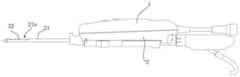
如图1至图6所示,本例示意一种活检手术装置,包括相连接的手柄1和刀具组件2,刀具组件2包括同轴设置的外刀管21和内刀管22,外刀管21的前端具有穿刺尖端,外刀管21靠近前端的侧面开设有取样窗口21a,内刀管22前端有切削刃,内刀管22与外刀管21套接,内刀管22内套于外刀管21或内刀管22外套于外刀管21,内刀管22能够相对于外刀管21轴向移动;As shown in Figures 1 to 6, this example illustrates a biopsy device, including a connected handle 1 and a
手柄1内设置有电机11,电机11与内刀管22之间通过传动机构连接,驱动内刀管22沿轴向(前后方向)运动,改变内刀管前端停止在所述外刀管取样窗口轴向的任意位置,以无级调节所述内刀管让出或遮挡取样窗口21a的长度,从而调节用于吸入组织的取样窗口21a的实际开窗长度,即实际使用的取样窗口21a的轴向尺寸。The handle 1 is provided with a
穿刺时内刀管22位于最前端将取样窗口21a封闭,穿刺到位置后内刀管22再向后运动让出取样窗口21a,组织在负压条件下被吸入取样窗口21a,此时内刀向前运动或前进同时并旋转,将进入取样窗口21a的组织切下,再通过大气压将切下的组织经过内刀管运送至样本收集盒。内刀管22可以在将取样窗口21a完全封闭(图4状态)至完全打开之间(图5状态)的位置调节,从而可以根据取样要求连续调节的取样窗口21a的实际开窗大小。When puncturing, the
其中,活检手术装置取样窗口的开窗大小调节方法包括:获取输入指令,输入指令至少包含取样开窗长度的设定值,例如可以通过手柄1上的按键输入或者触屏输入开窗长度参数,或者输入增加/减少的相对量,即开窗长度的调节值,通过输入的调节值可以计算出取样开窗长度的设定值;然后根据实际需要的开窗长度确定内刀管22的轴向移动距离,即根据内刀管22当前位置和开窗长度的设定值确定,例如当内刀管22的前端与取样窗口21a前端平齐时,内刀管22向后移动距离即为开窗长度;当内刀管22的前端向前超过取样窗口21a前端时,则内刀管22向后移动距离需大于输入的开窗长度,差值为内刀管22前端超出取样窗口21a前端的距离,该距离是活检手术装置制造时就确定的,根据相对位置来确定内刀管22的移动距离,如图6和图7所示;Wherein, the method for adjusting the size of the fenestration of the sampling window of the biopsy device includes: obtaining an input command, the input command at least includes a set value of the length of the sampling fenestration, for example, the parameter of the fenestration length can be input through the buttons on the handle 1 or the touch screen, Or input the relative amount of increase/decrease, i.e. the adjustment value of the window length, the set value of the sampling window length can be calculated by the input adjustment value; then determine the axial direction of the
之后,根据传动机构的传动关系,计算出内刀管22轴向移动距离所对应的电机转动圈数;从而控制所述电机按照所述转动圈数进行旋转,使所述内刀管22轴向移动,直至取样窗口21a达到指定的开窗长度为止。Afterwards, according to the transmission relationship of the transmission mechanism, the number of motor rotations corresponding to the axial movement distance of the
对于电机的转动圈数可用霍尔传感器检测,当转动完指定圈数后停止转动。The number of rotations of the motor can be detected by the Hall sensor, and it will stop after the specified number of rotations.
其中,输入设备、驱动器、霍尔传感器分别与控制器连接,输入设备可以是按键、触摸屏等,控制器内存储有内刀管22轴向移动距离与电机转动圈数的对应关系计算方式,当控制器获取输入设备的输入指令后,根据内刀管22与取样窗口21a的相对位置关系,计算出内刀管22需轴向移动的距离,然后根据当前传动机构的传动关系得出电机需要转动的圈数,利用驱动器驱使电机按照确定的圈数转动,同时霍尔传感器检测电机的转动圈数,并反馈至控制器,实时获取电机转动圈数,当达到对应圈数后,控制器通过驱动器控制电机停转。内刀管22可以在将取样窗口21a完全封闭至完全打开之间的位置调节,从而可以调节取样窗口21a的实际开窗长度,以适应不同取样尺寸的需求,并且通过内刀管22轴向移动距离与电机转动圈数的对应关系,通过控制电机转动圈数,可精确控制取样窗口21a的开窗长度,并能根据需要实时进行调节。Wherein, the input device, the driver, and the Hall sensor are respectively connected with the controller, and the input device can be a button, a touch screen, etc., and the controller stores the calculation method of the corresponding relationship between the axial movement distance of the
上述的控制器可以是通用处理器,包括中央处理器(Central Processing Unit,简称CPU)、网络处理器(Network Processor,简称NP)等;还可以是数字信号处理器(Digital Signal Processing,简称DSP)、专用集成电路(Application SpecificIntegrated Circuit,简称ASIC)、现场可编程门阵列(Field-Programmable Gate Array,简称FPGA)或者其他可编程逻辑器件、分立门或者晶体管逻辑器件、分立硬件组件。The above-mentioned controller can be a general-purpose processor, including a central processing unit (Central Processing Unit, referred to as CPU), a network processor (Network Processor, referred to as NP), etc.; it can also be a digital signal processor (Digital Signal Processing, referred to as DSP) , Application Specific Integrated Circuit (ASIC for short), Field Programmable Gate Array (Field-Programmable Gate Array, FPGA for short) or other programmable logic devices, discrete gate or transistor logic devices, discrete hardware components.
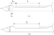
其中,如图6所示,当内刀管22的当前位置为初始位置时(即内刀管位于最前端将取样窗口封闭),内刀管22的轴向移动距离L=S1+L0;其中S1为所述输入的开窗长度的设定值;其中,L0为内刀管22位于初始位置时内刀管22前端到取样窗口21a前端的距离;Wherein, as shown in FIG. 6, when the current position of the
当所述内刀管22的当前位置不在初始位置时,分两种情况,当Ln≤L0时,说明内刀管22位于初始位置至取样窗口21a的前端之间,内刀管22的轴向移动距离L=S1+(L0-Ln),需移动的距离大于设定值;当Ln≥L0时,说明内刀管22位于取样窗口21a的前端的后侧,需移动的距离小于设定值,L=S1-(Ln-L0);其中,Ln为内刀管22前端到初始位置的距离。当L>0时,内刀管22后退,当L<0时,内刀管22向前运动。When the current position of the
如图7中(a)所示为内刀管22的当前位置,图7中(b)所示为内刀管22的最终调节位置,内刀管22的当前位置在取样窗口21a前端的后方,此时内刀管22的轴向移动距离为L=S1-(Ln-L0);当Ln≤L0时,计算方式相似。Shown in Figure 7 (a) is the current position of the
对于活检手术装置的传动结构,根据不同的传动结构具有不同的传动比计算方式:For the transmission structure of the biopsy surgical device, there are different transmission ratio calculation methods according to different transmission structures:
在一个实施例中,电机11的输出端与内刀管22之间直接通过螺纹连接,内刀管22轴向运动,此时电机11旋转一圈则,内刀管22轴向移动一个螺距P,内刀管22轴向移动距离L对应的电机转动圈数
具体地如图8所示,第一电机11的输出端固定连接有与其同步转动的传动件16,传动件16上设置有第一螺纹段,第一螺纹段可以是内螺纹或者外螺纹,内刀管22的后部设置与第一螺纹段相配合的第二螺纹段,P为第一螺纹段或第二螺纹段的螺距;传动件16直接与内刀管22的后部螺纹套设,在刀具组件或手柄上设置限位限制内刀管22转动,使内刀管22做轴向运动。Specifically as shown in Figure 8, the output end of the
如图9所示,在又一实施例中,第一电机11的输出端固定连接有与其同步转动的传动件16,传动件16上设置有第一螺纹段,第一螺纹段可以是内螺纹或者外螺纹,内刀管22上的传动套25,传动套25上设置有与第一螺纹段配合的第二螺纹段,传动件16与传动套25螺纹套接,传动套25与内刀管22之间轴向固定,周向相对转动地设置,从而在第一电机11转动时通过传动套25带动内刀管22轴向运动,使内刀管22前端停止在外刀管21的取样窗口21a轴向的任意位置。本例适用于内刀管22不旋转,只轴向运动的活检手术装置,可在刀具组件或手柄上设置限位限制内刀管22转动。As shown in Figure 9, in yet another embodiment, the output end of the
如图10所示,在一个实施方式中,传动机构包括相啮合的第一主动齿轮13和第一从动齿轮23,第一电机11的输出端连接有输出轴12,第一主动齿轮13套设在输出轴12上,并随输出轴12转动,内刀管22上设置有外螺纹段(即第三螺纹段),第一从动齿轮23的内壁设置有内螺纹(即第四螺纹段),该第一从动齿轮23套在内刀管22的外螺纹段上,与内刀管22螺纹配合,通过螺纹副配合,驱动内刀管22轴向运动,所述第一电机11驱动第一主动齿轮13转动,使第一从动齿轮23带动内刀管22沿轴向移动,并使内刀管22前端停止在外刀管21的取样窗口21a轴向的任意位置,从而改变内刀管22让出或遮挡取样窗口21a的尺寸。As shown in Figure 10, in one embodiment, the transmission mechanism includes a meshing
本例中为便于制造,内刀管22上固套有传动套25,传动套25上设置外螺纹与第一从动齿轮23配合。当然其他实施方式中,第一从动齿轮23轴向延伸出带外螺纹的轴部,该轴部伸入内刀管22中,并与其螺纹配合。In this example, for the convenience of manufacture, a
上述实施方式,既可适用于内刀管22旋转切割的活检手术装置,也可适用于内刀管22不旋转,只轴向运动的活检手术装置。The above-mentioned embodiment can be applied to a biopsy operation device in which the
上述结构通过齿轮组和螺纹传动,第一从动齿轮23转动一圈,内刀管22轴向移动一个螺距,电机11转动D/B圈,则内刀管22轴向移动距离L对应的电机11转动圈数
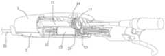
如图11所示,在一个实施方式中,传动机构包括第一传动结构和第二传动结构,电机通过第二传动结构带动内刀管22绕自身轴线旋转,第一传动结构的输出部外套在内刀管22上,并与内刀管22之间通过螺纹配合;输出部与内刀管22的旋转方向相同,输出部与内刀管22之间具有转速差,通过转速差和螺纹结构带动内刀管22沿轴向移动。从而在内刀管22高转速旋转的同时,实现轴向上较慢的移动调节,利于精确调节。As shown in Figure 11, in one embodiment, the transmission mechanism includes a first transmission structure and a second transmission structure, the motor drives the
如图11和图12所示,第一传动结构包括相啮合的第一主动齿轮13和第一从动齿轮23,第一从动齿轮23即为第一传动结构的输出部,电机11的输出端连接有输出轴12,第一主动齿轮13套设在输出轴12上,并随输出轴12转动,内刀管22上设置有外螺纹段(第五螺纹段),第一从动齿轮23的内壁设置有内螺纹(第六螺纹段),该第一从动齿轮23套在内刀管22的外螺纹段上,与内刀管22螺纹配合。As shown in Fig. 11 and Fig. 12, the first transmission structure includes the
电机11与内刀管22之间通过第二传动结构传递扭矩,以驱动内刀管22旋转,其中,第二传动结构包括相啮合的第二主动齿轮14和第二从动齿轮24,第二主动齿轮14设置在电机11的输出轴12上,并随所述输出轴12同步转动,第二从动齿轮24同轴套设在内刀管22上,并与内刀管22之间周向相对固定、轴向可相对滑动地设置,即内刀管22随第二从动齿轮24转动,但内刀管22可相对于第二从动齿轮24轴向滑动,并在滑动过程中仍然传递扭矩。Torque is transmitted between the
具体地,传动机构还包括固定套设在内刀管22上的传动套25,传动套25上设置有外螺纹,所述第一从动齿轮23套设在传动套25上,与传动套25螺纹配合。Specifically, the transmission mechanism also includes a
上述结构,内刀管22由传动组件带动绕自身轴线旋转,即与第二从动齿轮24同步转动,同时第一从动齿轮23与内刀管22螺纹配合,内刀管22的转动方向与第一从动齿轮23的转动方向相同,但转速不同,存在转速差,该转速差通过螺纹驱动内刀管22轴向运动。In the above structure, the
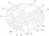
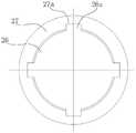
在一个实施方式中,传动套25轴向延伸形成延伸段26,第二从动齿轮24的其中一端固定连接有套筒27,套筒27外套在延伸段26上,并与延伸段26通过凹凸结构配合传递扭矩,且传动套25可相对于套筒27轴向滑动,以实现轴向相对移动的过程中保持扭矩传递。In one embodiment, the
如图13所示,在一个实施例中,所述套筒27的内壁沿内刀管22轴向开设有凹槽27a,凹槽27a沿周向分布为多个,延伸段26上设置与凹槽27a对应的凸起26a,且凹槽27a沿内刀管22轴向的长度大于/或小于凸起26a沿内刀管22轴向的长度,当然也可以通过键槽或花键配合。As shown in Figure 13, in one embodiment, the inner wall of the
本例中,刀具组件2还包括支撑壳体28,内刀管22和外刀管21均安装在支撑壳体28上,支撑壳体28上设置有传动窗口,第一从动齿轮23和第二从动齿轮24部分地从传动窗口伸出支撑壳体28,支撑壳体28上设置有用于对第一从动齿轮23和第二从动齿轮24轴向定位的定位结构,使得第一从动齿轮23和第二从动齿轮24轴向位置固定,只做旋转运动,本例中依靠传动窗口和支撑壳体28内壁形成的台阶28b轴向定位,为保证支撑的同时减小摩擦,支撑壳体28内壁多根凸筋28a,套筒27的外壁支撑在凸筋28a上。In this example, the
根据上述传动结构,通过内刀管22轴向移动距离L计算电机转动圈数的过程如下:According to the above transmission structure, the process of calculating the number of rotations of the motor through the axial movement distance L of the
第一主动齿轮13和第二主动齿轮14均连接在电机的输出轴上,转速相同;由于第一主动齿轮13、第二主动齿轮14、第一从动齿轮23、第二从动齿轮24的齿数均不同,导致两个齿轮组的传动比不一样,所以第一从动齿轮23和第二从动齿轮24的转速不一样,且第二从动齿轮24的转速与内刀管22绕自身轴线转动的转速相同;The
第一从动齿轮23与第二从动齿轮24的转速差为N1:The rotational speed difference between the first driven

其中,N为第一主动齿轮13和第二主动齿轮14的转速,
由以上式可知,第一从动齿轮23比第二从动齿轮24转速快N1。传动套25与第二从动齿轮24同步转动,转速相同,即第一从动齿轮23比传动套25的转速快N1。因为第二从动齿轮24、第一从动齿轮23轴向固定,所以第一从动齿轮23与传动套25的转速差通过第一从动齿轮23的螺纹使得传动套25前进或者后退(通过电机改变旋转方向实现前进或者后退),由于内刀管22与传动套25之间轴向固定,从而实现内刀管22的前进或者后退。It can be seen from the above formula that the first driven
其中,第一从动齿轮23的转速可以快于第二从动齿轮24,或者慢于第二从动齿轮24;快慢以及电机的旋转方向共同决定内刀管22前进或者后退。Wherein, the rotational speed of the first driven
内刀管22输出转速
内刀管22前进后退的快慢与两个从动齿轮的转速差以及螺纹的螺距有关,内刀管22进给速率
当第一从动齿轮23相对第二从动齿轮24旋转1圈,内刀管22前进距离为一个螺距P。因为第一从动齿轮23和第二从动齿轮24转速差系数为

当内刀管22轴向移动距离为L时,第二主动齿轮14、第一主动齿轮13和电机均旋转X圈,则


为便于医生直观地操作,取样窗口21a的开窗长度沿轴向调节的最小单元为E,即所述内刀管22每次可沿轴向移动一个最小单元E,最小单元E的取值范围为0.1mm-2mm,例如0.1mm、1mm、1.5mm、2mm等,并可连续移动多个相同的最小单元;即例如活检手术装置的开窗长度的最小调节单元为0.1mm时,每增减一次移动0.1mm,可连续增加或者减少多个0.1mm,每个活检手术装置上的最小单元取值唯一;各次移动距离相同,从而实现移动距离的连续、精细化调节;以实现取样窗口21a实际开窗长度的连续调节。In order to facilitate the intuitive operation of the doctor, the minimum unit of axial adjustment of the opening length of the
调节过程中可以是直接输入开窗长度的最终参数,例如25mm,也可以是输入增量参数,例如在原有开窗长度基础上增加或减少5mm。During the adjustment process, the final parameter of the window opening length can be directly input, such as 25mm, or an incremental parameter can be input, such as increasing or decreasing 5mm on the basis of the original window opening length.
活检手术装置工作时,穿刺前及穿刺过程中,内刀管22移动至最前端位置将取样窗口21a封闭,穿刺到位后,根据取样尺寸要求,通过电机11带动内刀管22向后运动,直到取样窗口21的实际开窗长度与输入值对应,然后通过负压装置从内刀管22的后端抽吸,将组织吸入取样窗口21中,完成后,驱动内刀管22向前运动并高速旋转,将组织切割下来并容纳在内刀管22的前端,完成取样。When the biopsy device is in operation, before and during the puncture, the
本实施例,内刀管22可以在将取样窗口21a完全封闭至取样窗口21a完全打开之间的位置连续调节,从而调节取样窗口21a的实际长度,可以实现内刀管22前后位置的连续调节,从而可以根据取样要求实时、连续调节取样窗口21a的开窗长度,以满足不同大小病灶的精准切除需求。在具体的实施例中,可实现最小开窗仅为5mm,满足微小病灶精准切除的需求,最大程度保留周围的正常组织;最大开窗可达30mm,单次切除可获得更大样本量,提升切除效率,缩短手术时间,满足较大病灶的手术需求。In this embodiment, the
任何熟悉此技术的人士皆可在不违背本发明的精神及范畴下,对上述实施例进行修饰或改变。因此,举凡所属技术领域中具有通常知识者在未脱离本发明所揭示的精神与技术思想下所完成的一切等效修饰或改变,仍应由本发明的权利要求所涵盖。Anyone skilled in the art can modify or change the above-mentioned embodiments without departing from the spirit and scope of the present invention. Therefore, all equivalent modifications or changes made by those skilled in the art without departing from the spirit and technical ideas disclosed in the present invention should still be covered by the claims of the present invention.
Claims (10)


Priority Applications (5)
| Application Number | Priority Date | Filing Date | Title |
|---|---|---|---|
| CN202111355495.6ACN114027888B (en) | 2021-11-16 | 2021-11-16 | Windowing size adjusting method for sampling window of biopsy surgical device |
| KR1020247004499AKR20240032975A (en) | 2021-11-16 | 2022-05-26 | Method and control device for adjusting the opening size of the sampling port of the biopsy surgical device |
| PCT/CN2022/095130WO2023087657A1 (en) | 2021-11-16 | 2022-05-26 | Window opening size adjustment method for sampling window of biopsy surgical device and control device |
| EP22894201.7AEP4349273A4 (en) | 2021-11-16 | 2022-05-26 | Window opening size adjustment method for a specimen window of a surgical biopsy device and control device |
| US18/292,111US20240341737A1 (en) | 2021-11-16 | 2022-05-26 | Method and control device for adjusting opening size of sampling window of biopsy surgical device |
Applications Claiming Priority (1)
| Application Number | Priority Date | Filing Date | Title |
|---|---|---|---|
| CN202111355495.6ACN114027888B (en) | 2021-11-16 | 2021-11-16 | Windowing size adjusting method for sampling window of biopsy surgical device |
Publications (2)
| Publication Number | Publication Date |
|---|---|
| CN114027888A CN114027888A (en) | 2022-02-11 |
| CN114027888Btrue CN114027888B (en) | 2022-11-15 |
Family
ID=80137843
Family Applications (1)
| Application Number | Title | Priority Date | Filing Date |
|---|---|---|---|
| CN202111355495.6AActiveCN114027888B (en) | 2021-11-16 | 2021-11-16 | Windowing size adjusting method for sampling window of biopsy surgical device |
Country Status (5)
| Country | Link |
|---|---|
| US (1) | US20240341737A1 (en) |
| EP (1) | EP4349273A4 (en) |
| KR (1) | KR20240032975A (en) |
| CN (1) | CN114027888B (en) |
| WO (1) | WO2023087657A1 (en) |
Families Citing this family (4)
| Publication number | Priority date | Publication date | Assignee | Title |
|---|---|---|---|---|
| CN114027888B (en)* | 2021-11-16 | 2022-11-15 | 重庆西山科技股份有限公司 | Windowing size adjusting method for sampling window of biopsy surgical device |
| CN116636884A (en)* | 2023-05-31 | 2023-08-25 | 重庆西山科技股份有限公司 | Single motor power handle and biopsy device |
| CN116687460A (en)* | 2023-05-31 | 2023-09-05 | 重庆西山科技股份有限公司 | Coaxial plug-in biopsy device |
| CN117064456B (en)* | 2023-10-17 | 2024-02-02 | 江西省水产科学研究所(江西省鄱阳湖渔业研究中心、江西省渔业资源生态环境监测中心) | Automatic sampling device for crucian immune tissues |
Citations (8)
| Publication number | Priority date | Publication date | Assignee | Title |
|---|---|---|---|---|
| US6436054B1 (en)* | 1998-11-25 | 2002-08-20 | United States Surgical Corporation | Biopsy system |
| WO2008076712A2 (en)* | 2006-12-13 | 2008-06-26 | Ethicon Endo-Surgery, Inc. | Biopsy device, system and method |
| US9078640B1 (en)* | 2014-12-02 | 2015-07-14 | Byungseol An | Disposable biopsy devices and methods of obtaining tissue biopsy samples using same |
| WO2016090023A1 (en)* | 2014-12-02 | 2016-06-09 | An Byungseol | Disposable biopsy devices and methods of obtaining tissue biopsy samples using same |
| CN207084843U (en)* | 2017-01-20 | 2018-03-13 | 重庆西山科技股份有限公司 | Medical Operating Components |
| CN209529190U (en)* | 2018-12-25 | 2019-10-25 | 重庆西山科技股份有限公司 | Repeatedly sampling biopsy device |
| CN112510591A (en)* | 2020-10-26 | 2021-03-16 | 国网安徽省电力有限公司电力科学研究院 | Wire stripping device and control method thereof |
| CN113017709A (en)* | 2019-12-25 | 2021-06-25 | 深圳成川医疗有限公司 | Biopsy needle and biopsy device with same |
Family Cites Families (34)
| Publication number | Priority date | Publication date | Assignee | Title |
|---|---|---|---|---|
| US4461305A (en)* | 1981-09-04 | 1984-07-24 | Cibley Leonard J | Automated biopsy device |
| US6440147B1 (en)* | 1998-09-03 | 2002-08-27 | Rubicor Medical, Inc. | Excisional biopsy devices and methods |
| US6120462A (en)* | 1999-03-31 | 2000-09-19 | Ethicon Endo-Surgery, Inc. | Control method for an automated surgical biopsy device |
| DE502005002984D1 (en)* | 2005-01-24 | 2008-04-10 | Ami Gmbh | Device for the surgical closure of a trocar puncture |
| US9345457B2 (en)* | 2006-12-13 | 2016-05-24 | Devicor Medical Products, Inc. | Presentation of biopsy sample by biopsy device |
| US8206316B2 (en)* | 2009-06-12 | 2012-06-26 | Devicor Medical Products, Inc. | Tetherless biopsy device with reusable portion |
| CN101669809B (en)* | 2009-09-24 | 2010-12-01 | 上海交通大学 | Active Controllable Capsule Endoscopy Robotic System |
| US9060760B2 (en)* | 2011-08-18 | 2015-06-23 | Hologic, Inc. | Tissue removal system |
| CN104039236B (en)* | 2011-10-15 | 2016-06-15 | 转化医药7有限责任公司 | Soft tissue core biopsy device and method |
| US9155527B2 (en)* | 2013-08-22 | 2015-10-13 | Transmed7, Llc | Soft tissue coring biopsy devices and methods |
| CN203688274U (en)* | 2013-11-15 | 2014-07-02 | 中国科学院生物物理研究所 | Tissue chip sampling gun |
| CN104188693A (en)* | 2014-07-04 | 2014-12-10 | 杭州通达控制系统有限公司 | Portable circumferential friction spiral cutting biopsy and operation device controlled by microcomputer |
| CN105796135A (en)* | 2016-03-03 | 2016-07-27 | 上海导向医疗系统有限公司 | Vacuum-assisted mammary gland sample biopsy and rotary cutting system |
| EP3544518B1 (en)* | 2016-11-23 | 2025-10-15 | C. R. Bard, Inc. | Single insertion multiple sample biopsy apparatus |
| KR102307399B1 (en)* | 2016-11-30 | 2021-10-01 | 충칭 시산 사이언스 앤드 테크놀로지 컴퍼니 리미티드 | Rotary Cutting Tools and Rotary Cutting Actuation Assemblies |
| CN206745383U (en)* | 2016-11-30 | 2017-12-15 | 重庆西山科技股份有限公司 | Rotary-cut sampling operation component |
| CN106388875B (en)* | 2016-11-30 | 2023-07-04 | 重庆西山科技股份有限公司 | Rotary cutting operation components |
| DK3554387T3 (en)* | 2016-12-15 | 2022-01-31 | Bard Inc C R | BIOPSY DEVICE WITH A LINEAR ENGINE DRIVE |
| CN206745423U (en)* | 2016-12-30 | 2017-12-15 | 重庆西山科技股份有限公司 | medical cutting device |
| US11116483B2 (en)* | 2017-05-19 | 2021-09-14 | Merit Medical Systems, Inc. | Rotating biopsy needle |
| WO2019046131A1 (en)* | 2017-08-28 | 2019-03-07 | RELIGN Corporation | Arthroscopic devices and methods |
| JP7346461B2 (en)* | 2018-02-08 | 2023-09-19 | リマカ メディカル リミテッド | biopsy device |
| CN109199464B (en)* | 2018-10-31 | 2024-04-05 | 重庆西山科技股份有限公司 | Biopsy device with multi-chamber sample holder |
| CN210644068U (en)* | 2019-05-07 | 2020-06-02 | 上海三埃弗电子有限公司 | Breast rotary cutter |
| US12336751B2 (en)* | 2019-08-26 | 2025-06-24 | Aulea Medical, Inc. | Surgical device and methods |
| CN211534548U (en)* | 2019-12-25 | 2020-09-22 | 深圳成川医疗有限公司 | Biopsy needle and biopsy device with same |
| CN111700650A (en)* | 2020-03-30 | 2020-09-25 | 苏州碧科维医疗技术有限公司 | Vacuum-assisted breast biopsy system |
| CN213606537U (en)* | 2020-09-03 | 2021-07-06 | 重庆西山科技股份有限公司 | Biopsy surgical device and biopsy surgical system |
| CN214157384U (en)* | 2020-09-03 | 2021-09-10 | 重庆西山科技股份有限公司 | Biopsy surgical device and biopsy surgical system |
| CN112587098A (en)* | 2020-12-23 | 2021-04-02 | 班海鑫 | Department of neurology is with detecting accurate check out test set |
| CN113243941B (en)* | 2021-04-30 | 2023-06-27 | 重庆西山科技股份有限公司 | Mode-adjustable biopsy system |
| CN113476111B (en)* | 2021-07-08 | 2023-01-24 | 上海导向医疗系统有限公司 | Mammary gland rotary cutting system, motor control system and control method thereof |
| CN114027888B (en)* | 2021-11-16 | 2022-11-15 | 重庆西山科技股份有限公司 | Windowing size adjusting method for sampling window of biopsy surgical device |
| CN216495408U (en)* | 2021-11-16 | 2022-05-13 | 重庆西山科技股份有限公司 | Biopsy surgical device with infinitely adjustable sampling window size |
- 2021
- 2021-11-16CNCN202111355495.6Apatent/CN114027888B/enactiveActive
- 2022
- 2022-05-26EPEP22894201.7Apatent/EP4349273A4/enactivePending
- 2022-05-26USUS18/292,111patent/US20240341737A1/enactivePending
- 2022-05-26WOPCT/CN2022/095130patent/WO2023087657A1/ennot_activeCeased
- 2022-05-26KRKR1020247004499Apatent/KR20240032975A/enactivePending
Patent Citations (9)
| Publication number | Priority date | Publication date | Assignee | Title |
|---|---|---|---|---|
| US6436054B1 (en)* | 1998-11-25 | 2002-08-20 | United States Surgical Corporation | Biopsy system |
| JP4559630B2 (en)* | 1998-11-25 | 2010-10-13 | ユナイテッド ステイツ サージカル コーポレイション | Biopsy system |
| WO2008076712A2 (en)* | 2006-12-13 | 2008-06-26 | Ethicon Endo-Surgery, Inc. | Biopsy device, system and method |
| US9078640B1 (en)* | 2014-12-02 | 2015-07-14 | Byungseol An | Disposable biopsy devices and methods of obtaining tissue biopsy samples using same |
| WO2016090023A1 (en)* | 2014-12-02 | 2016-06-09 | An Byungseol | Disposable biopsy devices and methods of obtaining tissue biopsy samples using same |
| CN207084843U (en)* | 2017-01-20 | 2018-03-13 | 重庆西山科技股份有限公司 | Medical Operating Components |
| CN209529190U (en)* | 2018-12-25 | 2019-10-25 | 重庆西山科技股份有限公司 | Repeatedly sampling biopsy device |
| CN113017709A (en)* | 2019-12-25 | 2021-06-25 | 深圳成川医疗有限公司 | Biopsy needle and biopsy device with same |
| CN112510591A (en)* | 2020-10-26 | 2021-03-16 | 国网安徽省电力有限公司电力科学研究院 | Wire stripping device and control method thereof |
Also Published As
| Publication number | Publication date |
|---|---|
| KR20240032975A (en) | 2024-03-12 |
| EP4349273A1 (en) | 2024-04-10 |
| WO2023087657A1 (en) | 2023-05-25 |
| EP4349273A4 (en) | 2025-05-07 |
| CN114027888A (en) | 2022-02-11 |
| US20240341737A1 (en) | 2024-10-17 |
Similar Documents
| Publication | Publication Date | Title |
|---|---|---|
| CN114027888B (en) | Windowing size adjusting method for sampling window of biopsy surgical device | |
| EP1951127B1 (en) | A biopsy needle assembly and a device for taking a tissue sample | |
| US10285673B2 (en) | Biopsy device | |
| CN219289529U (en) | Mammary gland rotary-cut biopsy needle | |
| JP2012520726A (en) | Biological tissue examination apparatus having rotational cutting | |
| CN107184255A (en) | A kind of ultrasonic per rectum prostate biopsy mechanism | |
| CN216495408U (en) | Biopsy surgical device with infinitely adjustable sampling window size | |
| CN106691550A (en) | Breast tissue puncture biopsy needle | |
| KR20250112880A (en) | Control method of biopsy sampling device and biopsy sampling device | |
| CN114711838A (en) | Rotary-cut mammary gland biopsy equipment and method | |
| CN111603242A (en) | Catheter Manipulator and Catheter Assembly | |
| US20200015795A1 (en) | Biopsy device with self-reversing cutter drive | |
| CN207721863U (en) | A kind of prostate biopsy mechanism | |
| CN108852426A (en) | Organize quantitative cutting device | |
| RU2831302C2 (en) | Method and control device for adjusting size of opening of sampling window of surgical biopsy device | |
| CN117379116A (en) | Rotary cutting needle notch size adjustment method, rotary cutting needle notch size adjustment system and focus cutting method | |
| CN217987702U (en) | Single-arm puncture robot | |
| CN209186767U (en) | Negative pressure suction device for fine-needle aspiration biopsy with single-handed control | |
| CN210843183U (en) | Breast biopsy device | |
| CN217447857U (en) | Sawtooth type sleeve biopsy needle | |
| CN216908058U (en) | ERCP-based bile duct rotary cutter assembly | |
| CN215078991U (en) | Oncology Puncture Sampling Device | |
| CN219461232U (en) | Stepless-adjusting medical biopsy needle | |
| CN114469198A (en) | A breast linear cutting biopsy system | |
| CN209315922U (en) | Quantitative tissue cutter |
Legal Events
| Date | Code | Title | Description |
|---|---|---|---|
| PB01 | Publication | ||
| PB01 | Publication | ||
| SE01 | Entry into force of request for substantive examination | ||
| SE01 | Entry into force of request for substantive examination | ||
| GR01 | Patent grant | ||
| GR01 | Patent grant | ||
| CP03 | Change of name, title or address | ||
| CP03 | Change of name, title or address | Address after:No. 2 Kangzhu Road, Kangmei Street, Liangjiang New District, Yubei District, Chongqing 401123 Patentee after:CHONGQING XISHAN SCIENCE & TECHNOLOGY Co.,Ltd. Country or region after:China Address before:401121 Jupiter science and technology development center, Gaoxin Park, northern New District, Yubei District, Chongqing (No. 9, middle section of Huangshan Avenue) Patentee before:CHONGQING XISHAN SCIENCE & TECHNOLOGY Co.,Ltd. Country or region before:China |