CN113997124B - A system and method for acquiring visual image of tool wear surface for piston machining - Google Patents
A system and method for acquiring visual image of tool wear surface for piston machiningDownload PDFInfo
- Publication number
- CN113997124B CN113997124BCN202111485921.8ACN202111485921ACN113997124BCN 113997124 BCN113997124 BCN 113997124BCN 202111485921 ACN202111485921 ACN 202111485921ACN 113997124 BCN113997124 BCN 113997124B
- Authority
- CN
- China
- Prior art keywords
- grid
- tool
- parallel
- ultraviolet
- visual image
- Prior art date
- Legal status (The legal status is an assumption and is not a legal conclusion. Google has not performed a legal analysis and makes no representation as to the accuracy of the status listed.)
- Active
Links
Images


Classifications
- B—PERFORMING OPERATIONS; TRANSPORTING
- B23—MACHINE TOOLS; METAL-WORKING NOT OTHERWISE PROVIDED FOR
- B23Q—DETAILS, COMPONENTS, OR ACCESSORIES FOR MACHINE TOOLS, e.g. ARRANGEMENTS FOR COPYING OR CONTROLLING; MACHINE TOOLS IN GENERAL CHARACTERISED BY THE CONSTRUCTION OF PARTICULAR DETAILS OR COMPONENTS; COMBINATIONS OR ASSOCIATIONS OF METAL-WORKING MACHINES, NOT DIRECTED TO A PARTICULAR RESULT
- B23Q17/00—Arrangements for observing, indicating or measuring on machine tools
- B23Q17/09—Arrangements for observing, indicating or measuring on machine tools for indicating or measuring cutting pressure or for determining cutting-tool condition, e.g. cutting ability, load on tool
- B23Q17/0952—Arrangements for observing, indicating or measuring on machine tools for indicating or measuring cutting pressure or for determining cutting-tool condition, e.g. cutting ability, load on tool during machining
- B23Q17/0957—Detection of tool breakage
- B—PERFORMING OPERATIONS; TRANSPORTING
- B23—MACHINE TOOLS; METAL-WORKING NOT OTHERWISE PROVIDED FOR
- B23Q—DETAILS, COMPONENTS, OR ACCESSORIES FOR MACHINE TOOLS, e.g. ARRANGEMENTS FOR COPYING OR CONTROLLING; MACHINE TOOLS IN GENERAL CHARACTERISED BY THE CONSTRUCTION OF PARTICULAR DETAILS OR COMPONENTS; COMBINATIONS OR ASSOCIATIONS OF METAL-WORKING MACHINES, NOT DIRECTED TO A PARTICULAR RESULT
- B23Q17/00—Arrangements for observing, indicating or measuring on machine tools
- B23Q17/24—Arrangements for observing, indicating or measuring on machine tools using optics or electromagnetic waves
- B23Q17/2452—Arrangements for observing, indicating or measuring on machine tools using optics or electromagnetic waves for measuring features or for detecting a condition of machine parts, tools or workpieces
- B23Q17/2457—Arrangements for observing, indicating or measuring on machine tools using optics or electromagnetic waves for measuring features or for detecting a condition of machine parts, tools or workpieces of tools
Landscapes
- Engineering & Computer Science (AREA)
- Mechanical Engineering (AREA)
- Physics & Mathematics (AREA)
- Optics & Photonics (AREA)
- Investigating, Analyzing Materials By Fluorescence Or Luminescence (AREA)
- Length Measuring Devices By Optical Means (AREA)
Abstract
Translated fromChinese
Description
Translated fromChinese技术领域technical field
本发明涉及活塞加工用刀具视觉检测技术,具体涉及一种获取活塞加工用刀具磨损面视觉图像的系统和方法。The invention relates to a visual detection technology of a tool for piston processing, in particular to a system and a method for acquiring a visual image of a wear surface of a tool for piston processing.
背景技术Background technique
活塞加工时,刀具作为直接接触加工工件的部分,其加工状态对活塞加工质量会产生直接的影响,刀具的过度磨损会导致成品率的下降。因此,及时有效地监控刀具的工作状态显得十分必要。When the piston is processed, the tool is the part that directly contacts the workpiece, and its processing status will have a direct impact on the processing quality of the piston. Excessive wear of the tool will lead to a decline in the yield. Therefore, it is very necessary to monitor the working status of the cutting tool in time and effectively.
传统上,通过传感器直接或者间接测量刀具切削加工过程中一些信号变化量,从而检测刀具磨损或破损程度的状态参量。传感器将切削力信号、电机电流信号、振动信号以及刀具或工件表面加工状态图像信号灯转化成电信号,传入计算机进行下一步处理,从而解析描述刀具实时的状态信息。上世纪九十年代以来,图像处理和机器视觉为代表的刀具视觉检测技术在高性能工业处理器等技术的配合下不断地向前迈进。随着CCD和CMOS相机等图像传感器技术、图像处理理论和神经网络算法模型的完善,以及相关硬件不断发展成熟带来的硬件成本降低,基于图像处理的视觉检测理论和技术也逐渐应用于生产加工领域,基于机器视觉的刀具状态检测(Computer-Vision based Tool Condition Monitor,CVTCM)也应运而生,CVTCM是通过分析刀具磨损的图像,判断刀具的状态,进一步预测刀具的寿命。Traditionally, sensors are used to directly or indirectly measure some signal changes in the process of tool cutting, so as to detect the state parameters of tool wear or damage. The sensor converts cutting force signals, motor current signals, vibration signals, and tool or workpiece surface processing status image signals into electrical signals, which are transmitted to the computer for further processing, thereby analyzing and describing the real-time status information of the tool. Since the 1990s, tool visual inspection technology represented by image processing and machine vision has been continuously advancing with the cooperation of high-performance industrial processors and other technologies. With the improvement of image sensor technology such as CCD and CMOS camera, image processing theory and neural network algorithm model, and the reduction of hardware cost brought about by the continuous development and maturity of related hardware, visual inspection theory and technology based on image processing are gradually applied to production and processing. In the field of machine vision, the Computer-Vision based Tool Condition Monitor (CVTCM) also came into being. CVTCM judges the state of the tool by analyzing the image of the tool wear, and further predicts the life of the tool.
传统刀具磨损识别主要依靠机床操作者依靠自身经验和工艺标准要求通过对刀具表面状态的观察做出判断,但是依赖操作者自身经验的检测方法不仅具有效率低和可靠性差等的缺点,不同操作者之间的判断标准有时也会出现偏差。基于机器视觉的刀具磨损图像检测不仅可以统一标准,而且能够降低对操作者加工经验的要求,极大的提高加工效率。然而,现有技术中相机拍摄刀具图片后,通过人工阈值处理将灰度图转换成二值图,然后直接通过二值图像计算后刀面宽度,根据宽度值来判断刀具磨损状态。由于没有补充光源且磨损区域表面纹理不规则性,使用固定阈值分割二值图容易产生离散的黑色像素二值图像,导致测量结果误差较大。Traditional tool wear identification mainly relies on machine tool operators relying on their own experience and process standards to make judgments through observation of the tool surface state, but the detection method that relies on the operator's own experience not only has the disadvantages of low efficiency and poor reliability, different operators There are sometimes deviations between the judgment standards. Tool wear image detection based on machine vision can not only unify the standard, but also reduce the requirements for the operator's processing experience and greatly improve the processing efficiency. However, in the prior art, after the camera takes the picture of the tool, the grayscale image is converted into a binary image through artificial threshold processing, and then the flank width is directly calculated through the binary image, and the tool wear state is judged according to the width value. Since there is no supplementary light source and the surface texture of the worn area is irregular, using a fixed threshold to segment the binary image is easy to produce a discrete black pixel binary image, resulting in large errors in measurement results.
因此,本领域的技术人员致力于开发一种可以更为精确地获取刀具磨损面视觉图像的装置和方法。Therefore, those skilled in the art are devoting themselves to developing a device and method that can more accurately obtain visual images of tool wear surfaces.
发明内容Contents of the invention
为克服现有技术的上述不足,本发明的第一方面是提供一种获取活塞加工用刀具磨损面视觉图像的系统,包括平行紫外光源、相机、透明基板、透明PET蒙板和刀具,其中:In order to overcome the above-mentioned deficiencies in the prior art, the first aspect of the present invention provides a system for obtaining a visual image of the tool wear surface for piston processing, including a parallel ultraviolet light source, a camera, a transparent substrate, a transparent PET mask and a tool, wherein:
所述平行紫外光源用于提供平行紫外光,所述透明PET蒙板设置在所述透明基板之上,所述透明PET蒙板上设有格栅部,且所述格栅部包括多个相互垂直的平行贯通线槽构成的正方格栅;The parallel ultraviolet light source is used to provide parallel ultraviolet light, the transparent PET mask is arranged on the transparent substrate, the transparent PET mask is provided with a grid part, and the grid part includes a plurality of mutual A square grid composed of vertical parallel through-line slots;
所述刀具表面涂敷有紫外光致荧光颜料;The surface of the tool is coated with ultraviolet photoluminescent pigments;
所述相机被设置为通过拍摄由透过所述格栅部的紫外线在所述刀具上激发的荧光光线网格,从而可以获取活塞加工用刀具磨损面视觉图像。The camera is configured to capture a visual image of the wear surface of the tool used for piston machining by photographing the fluorescent light grid excited on the tool by the ultraviolet rays passing through the grid portion.
进一步,所述格栅部位于所述透明PET蒙板的中心。Further, the grid part is located at the center of the transparent PET mask.
更进一步,所述平行贯通线槽的宽度为300-500微米、间距为800-1000微米。Furthermore, the width of the parallel through grooves is 300-500 microns, and the pitch is 800-1000 microns.
进一步,所述紫外光致荧光颜料为无机紫外光致荧光颜料。Further, the ultraviolet photofluorescent pigment is an inorganic ultraviolet photofluorescent pigment.
进一步,所述平行紫外光源被设置为发出波长在320nm以下的紫外线。Further, the parallel ultraviolet light source is set to emit ultraviolet rays with a wavelength below 320nm.
进一步,所述透明PET蒙板上均匀分布有紫外吸收剂。Further, an ultraviolet absorber is uniformly distributed on the transparent PET mask.
本发明的第二方面是提供一种获取活塞加工用刀具磨损面视觉图像的方法,通过上述获取活塞加工用刀具磨损面视觉图像的系统进行,包括以下步骤:The second aspect of the present invention is to provide a method for obtaining a visual image of a tool wear surface for piston processing, which is carried out by the above-mentioned system for obtaining a visual image of a tool wear surface for piston processing, including the following steps:
(1)在刀具的表面涂敷紫外光致荧光颜料;(1) Coating ultraviolet photoluminescent pigments on the surface of the cutter;
(2)在透明基板上设置透明PET蒙板,在透明PET蒙板上设置由多个相互垂直的平行贯通线槽构成正方格栅的正方形格栅部;(2) A transparent PET mask is set on the transparent substrate, and a square grid part is set on the transparent PET mask to form a square grid by a plurality of mutually perpendicular parallel through-line grooves;
(3)由平行紫外光源发出的平行紫外光照射上述格栅部;(3) The parallel ultraviolet light emitted by the parallel ultraviolet light source irradiates the above-mentioned grid part;
(4)透过格栅部的紫外线在刀具上激发产生荧光光线网格;(4) The ultraviolet light passing through the grid part is excited on the tool to generate a fluorescent light grid;
(5)通过相机拍摄荧光光线网格,获取活塞加工用刀具磨损面视觉图像。(5) The fluorescent light grid is captured by the camera to obtain the visual image of the tool wear surface for piston machining.
进一步,所述格栅部位于所述透明PET蒙板的中心。Further, the grid part is located at the center of the transparent PET mask.
更进一步,所述平行贯通线槽的宽度为300-500微米、间距为800-1000微米。Furthermore, the width of the parallel through grooves is 300-500 microns, and the pitch is 800-1000 microns.
进一步,所述紫外光致荧光颜料为无机紫外光致荧光颜料。Further, the ultraviolet photofluorescent pigment is an inorganic ultraviolet photofluorescent pigment.
进一步,所述平行紫外光源被设置为发出波长在320nm以下的紫外线。Further, the parallel ultraviolet light source is set to emit ultraviolet rays with a wavelength below 320nm.
进一步,所述透明PET蒙板上均匀分布有紫外吸收剂。Further, an ultraviolet absorber is uniformly distributed on the transparent PET mask.
与现有技术相比,本发明的有益效果在于:本发明可以在刀具磨损面上获得包含荧光光线网格的视觉图像,且网格的大小可以根据格栅部中平行贯通线槽的宽度和间距以及格栅部与刀具之间的距离计算而得,也可方便地进行刀具磨损前和磨损后网格线的比较,有利于计算机提取磨损面的特征,提高计算机图像检测处理的准确度。Compared with the prior art, the present invention has the beneficial effect that: the present invention can obtain a visual image containing fluorescent light grids on the tool wear surface, and the size of the grids can be determined according to the width and The spacing and the distance between the grid part and the tool are calculated, and it is also convenient to compare the grid lines before and after tool wear, which is beneficial to the computer to extract the characteristics of the worn surface and improve the accuracy of computer image detection processing.
附图说明Description of drawings
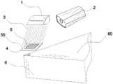
图1是一个较佳实施例中获取活塞加工用刀具磨损面视觉图像的系统的示意图;Fig. 1 is a schematic diagram of a system for obtaining a visual image of a tool wear surface for piston machining in a preferred embodiment;
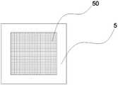
图2是一个较佳实施例中透明PET蒙板的示意图;Fig. 2 is a schematic diagram of a transparent PET mask in a preferred embodiment;
图3是一个较佳实施例中刀具的示意图;Fig. 3 is the schematic diagram of cutter in a preferred embodiment;
图4是一个较佳实施例中荧光光线网格的示意图;Fig. 4 is a schematic diagram of fluorescent light grid in a preferred embodiment;
如图标记如下:1-平行紫外光源、2-相机、3-平行紫外光、4-透明基板、5-透明PET蒙板、50-格栅部、6-刀具、60-无机紫外光致荧光颜料、7-刀具磨损面、8-磨损部分、9-荧光光线网格。The marks are as follows: 1-parallel ultraviolet light source, 2-camera, 3-parallel ultraviolet light, 4-transparent substrate, 5-transparent PET mask, 50-grid, 6-knife, 60-inorganic ultraviolet photofluorescence Pigment, 7-tool wear surface, 8-wear part, 9-fluorescent light grid.
具体实施方式Detailed ways
以下参考说明书附图介绍本发明的多个优选实施例,使其技术内容更加清楚和便于理解。本发明可以通过许多不同形式的实施例来得以体现,本发明的保护范围并非仅限于文中提到的实施例。The following describes several preferred embodiments of the present invention with reference to the accompanying drawings, so as to make the technical content clearer and easier to understand. The present invention can be embodied in many different forms of embodiments, and the protection scope of the present invention is not limited to the embodiments mentioned herein.
根据本发明的一种获取活塞加工用刀具磨损面视觉图像的系统如图1所示,包括平行紫外光源1、相机2、透明基板4、透明PET蒙板5和刀具6;其中:平行紫外光源1可提供高平行度的平行紫外光3(例如CN205535338U),设置在透明基板4之上的透明PET蒙板5可以屏蔽320nm(UVb和UVc)以下的紫外线,屏蔽UVa(320-400nm)也可以通过添加紫外吸收剂实现。透明PET蒙板5中心设置有正方形的格栅部50,格栅部50由包括多个相互垂直的宽度为300-500微米、间距为800-1000微米的平行贯通线槽构成的正方格栅,如图2所示。According to the present invention, a system for obtaining a visual image of a tool wear surface for piston processing is shown in Figure 1, comprising a parallel
刀具6的表面涂敷有无机紫外光致荧光颜料60,该荧光颜料在紫外线照射下会呈现明亮荧光。现有技术中这种荧光颜料可由金属(锌、镉)硫化物或稀土氧化物与微量活性剂配合,经煅烧而成。The surface of the
平行紫外光源1发出的平行紫外光除透过格栅部50的部分以外,其余部分被透明PET蒙板5屏蔽。如图3、4所示,透过格栅部50的紫外线照射到刀具磨损面7,使刀具6上的无机紫外光致荧光颜料60发光,形成由荧光光线构成的荧光光线网格9,调整透明基板4、透明PET蒙板5和刀具6之间的距离可以调整荧光光线网格9的大小。由于刀具磨损面7上磨损部分8的无机紫外光致荧光颜料60随着刀具6的磨损而消失,故磨损部分8上不会产生激发的荧光光线网格9。由此,相机2可以拍摄得到以荧光光线网格9标识的刀具磨损面视觉图像,以用于接下来的计算机图像检测,以对刀具磨损状态进行测量。The parallel ultraviolet light emitted by the parallel
以上详细描述了本发明的较佳具体实施例。应当理解,本领域的普通技术无需创造性劳动就可以根据本发明的构思作出诸多修改和变化。因此,凡本技术领域中技术人员依本发明的构思在现有技术的基础上通过逻辑分析、推理或者有限的实验可以得到的技术方案,皆应在由权利要求书所确定的保护范围内。The preferred specific embodiments of the present invention have been described in detail above. It should be understood that those skilled in the art can make many modifications and changes according to the concept of the present invention without creative efforts. Therefore, all technical solutions that can be obtained by those skilled in the art based on the concept of the present invention through logical analysis, reasoning or limited experiments on the basis of the prior art shall be within the scope of protection defined by the claims.
Claims (3)
Translated fromChinesePriority Applications (1)
| Application Number | Priority Date | Filing Date | Title |
|---|---|---|---|
| CN202111485921.8ACN113997124B (en) | 2021-12-07 | 2021-12-07 | A system and method for acquiring visual image of tool wear surface for piston machining |
Applications Claiming Priority (1)
| Application Number | Priority Date | Filing Date | Title |
|---|---|---|---|
| CN202111485921.8ACN113997124B (en) | 2021-12-07 | 2021-12-07 | A system and method for acquiring visual image of tool wear surface for piston machining |
Publications (2)
| Publication Number | Publication Date |
|---|---|
| CN113997124A CN113997124A (en) | 2022-02-01 |
| CN113997124Btrue CN113997124B (en) | 2022-12-02 |
Family
ID=79931472
Family Applications (1)
| Application Number | Title | Priority Date | Filing Date |
|---|---|---|---|
| CN202111485921.8AActiveCN113997124B (en) | 2021-12-07 | 2021-12-07 | A system and method for acquiring visual image of tool wear surface for piston machining |
Country Status (1)
| Country | Link |
|---|---|
| CN (1) | CN113997124B (en) |
Family Cites Families (10)
| Publication number | Priority date | Publication date | Assignee | Title |
|---|---|---|---|---|
| KR100589110B1 (en)* | 2002-09-26 | 2006-06-13 | 가부시키가이샤 히다치 고쿠사이 덴키 | Apparatus and method for inspecting pattern defect |
| CN1251157C (en)* | 2002-12-27 | 2006-04-12 | 中国科学院自动化研究所 | Object three-dimensional model quick obtaining method based on active vision |
| US20050269742A1 (en)* | 2004-06-03 | 2005-12-08 | Wright Thomas S | Method for making tools for micro replication |
| JP2008116582A (en)* | 2006-11-01 | 2008-05-22 | Sharp Corp | Cleaning blade and image forming apparatus |
| CN103454287A (en)* | 2013-09-05 | 2013-12-18 | 深圳市维图视技术有限公司 | Glass tube defect visual detection method and device |
| CA2930172C (en)* | 2013-12-10 | 2018-08-07 | Halliburton Energy Services, Inc. | Continuous live tracking system for placement of cutting elements |
| DE112015000866T5 (en)* | 2014-02-19 | 2016-11-17 | Semiconductor Energy Laboratory Co., Ltd. | Light-emitting device and detachment method |
| CN108362228B (en)* | 2018-02-11 | 2020-10-30 | 西安知象光电科技有限公司 | Double-optical-machine-based optical knife grating hybrid three-dimensional measurement device and measurement method |
| CN111024723A (en)* | 2019-12-26 | 2020-04-17 | 苏州市建设工程质量检测中心有限公司 | Vision application device based on fluorescent coating and processing method |
| CN214559503U (en)* | 2021-01-03 | 2021-11-02 | 兰州交通大学 | A visual online detection system for tool wear in CNC machining centers |
- 2021
- 2021-12-07CNCN202111485921.8Apatent/CN113997124B/enactiveActive
Also Published As
| Publication number | Publication date |
|---|---|
| CN113997124A (en) | 2022-02-01 |
Similar Documents
| Publication | Publication Date | Title |
|---|---|---|
| EP3495077B1 (en) | Powder spreading quality test method and additive manufacturing device | |
| CN102937599B (en) | Non-destructive testing systems and method used for detecting a metal-containing object through X-ray detection | |
| Zhang et al. | Automatic detection of defects in tire radiographic images | |
| CN117250208A (en) | Machine vision-based nano-imprint wafer defect accurate detection system and method | |
| CN103308525B (en) | A kind of online test method for metal wire rod production and device | |
| CN107424144A (en) | Weld joint tracking image processing algorithm based on laser vision | |
| CN111591716A (en) | Photoelectric integrated intelligent detection device for belt damage condition of conveyor | |
| CN112326685A (en) | Online detection device and detection method for laser-induced damage of optical element | |
| DE112022005406B4 (en) | AI-based product surface inspection device and method | |
| CN104880841B (en) | Substrate prosthetic device and restorative procedure | |
| CN108629790A (en) | A kind of optical strip image threshold segmentation method based on depth residual error network | |
| CN104458764A (en) | Curved uneven surface defect identification method based on large-field-depth stripped image projection | |
| CN116794064B (en) | Defect detection method applied to monocrystalline silicon round bar | |
| CN105303573A (en) | Pin detection method and system for gold needle type element | |
| CN113997124B (en) | A system and method for acquiring visual image of tool wear surface for piston machining | |
| TW201543001A (en) | Tool inspection method and tool inspection device | |
| CN107948464A (en) | A kind of geometric correction method and system of the laterally offset of printed matter detection image | |
| CN117314829A (en) | Industrial part quality inspection method and system based on computer vision | |
| US20210080521A1 (en) | Magnetic particle inspection device | |
| TWI512284B (en) | Bubble inspection system for glass | |
| CN113189002B (en) | Online detection method and device for stripe defects of ultrathin electronic glass substrate | |
| CN118258815A (en) | Detection method for detecting flexible film sensor based on machine vision | |
| CN118115429A (en) | Material increase manufacturing structure and powder laying abnormality online monitoring, diagnosing and controlling system | |
| CN111754504B (en) | Chemical mixed bed layering detection method based on machine vision | |
| CN110465751B (en) | Wafer laser processing system |
Legal Events
| Date | Code | Title | Description |
|---|---|---|---|
| PB01 | Publication | ||
| PB01 | Publication | ||
| SE01 | Entry into force of request for substantive examination | ||
| SE01 | Entry into force of request for substantive examination | ||
| GR01 | Patent grant | ||
| GR01 | Patent grant |