CN113967016A - Puncture device and blood collection device - Google Patents
Puncture device and blood collection deviceDownload PDFInfo
- Publication number
- CN113967016A CN113967016ACN202110839694.8ACN202110839694ACN113967016ACN 113967016 ACN113967016 ACN 113967016ACN 202110839694 ACN202110839694 ACN 202110839694ACN 113967016 ACN113967016 ACN 113967016A
- Authority
- CN
- China
- Prior art keywords
- assembly
- holding portion
- blood collection
- frame body
- elastic member
- Prior art date
- Legal status (The legal status is an assumption and is not a legal conclusion. Google has not performed a legal analysis and makes no representation as to the accuracy of the status listed.)
- Granted
Links
- 239000008280bloodSubstances0.000titleclaimsabstractdescription144
- 210000004369bloodAnatomy0.000titleclaimsabstractdescription144
- 238000010241blood samplingMethods0.000claimsabstractdescription10
- 230000002787reinforcementEffects0.000claimsdescription4
- 230000014759maintenance of locationEffects0.000claims1
- 238000000034methodMethods0.000description8
- 206010012601diabetes mellitusDiseases0.000description4
- NOESYZHRGYRDHS-UHFFFAOYSA-NinsulinChemical compoundN1C(=O)C(NC(=O)C(CCC(N)=O)NC(=O)C(CCC(O)=O)NC(=O)C(C(C)C)NC(=O)C(NC(=O)CN)C(C)CC)CSSCC(C(NC(CO)C(=O)NC(CC(C)C)C(=O)NC(CC=2C=CC(O)=CC=2)C(=O)NC(CCC(N)=O)C(=O)NC(CC(C)C)C(=O)NC(CCC(O)=O)C(=O)NC(CC(N)=O)C(=O)NC(CC=2C=CC(O)=CC=2)C(=O)NC(CSSCC(NC(=O)C(C(C)C)NC(=O)C(CC(C)C)NC(=O)C(CC=2C=CC(O)=CC=2)NC(=O)C(CC(C)C)NC(=O)C(C)NC(=O)C(CCC(O)=O)NC(=O)C(C(C)C)NC(=O)C(CC(C)C)NC(=O)C(CC=2NC=NC=2)NC(=O)C(CO)NC(=O)CNC2=O)C(=O)NCC(=O)NC(CCC(O)=O)C(=O)NC(CCCNC(N)=N)C(=O)NCC(=O)NC(CC=3C=CC=CC=3)C(=O)NC(CC=3C=CC=CC=3)C(=O)NC(CC=3C=CC(O)=CC=3)C(=O)NC(C(C)O)C(=O)N3C(CCC3)C(=O)NC(CCCCN)C(=O)NC(C)C(O)=O)C(=O)NC(CC(N)=O)C(O)=O)=O)NC(=O)C(C(C)CC)NC(=O)C(CO)NC(=O)C(C(C)O)NC(=O)C1CSSCC2NC(=O)C(CC(C)C)NC(=O)C(NC(=O)C(CCC(N)=O)NC(=O)C(CC(N)=O)NC(=O)C(NC(=O)C(N)CC=1C=CC=CC=1)C(C)C)CC1=CN=CN1NOESYZHRGYRDHS-UHFFFAOYSA-N0.000description4
- 238000010304firingMethods0.000description3
- 102000004877InsulinHuman genes0.000description2
- 108090001061InsulinProteins0.000description2
- 210000000078clawAnatomy0.000description2
- 239000000084colloidal systemSubstances0.000description2
- 208000037265diseases, disorders, signs and symptomsDiseases0.000description2
- 229940125396insulinDrugs0.000description2
- 208000024172Cardiovascular diseaseDiseases0.000description1
- 206010010071ComaDiseases0.000description1
- WQZGKKKJIJFFOK-GASJEMHNSA-NGlucoseNatural productsOC[C@H]1OC(O)[C@H](O)[C@@H](O)[C@@H]1OWQZGKKKJIJFFOK-GASJEMHNSA-N0.000description1
- 208000013016HypoglycemiaDiseases0.000description1
- 206010023379KetoacidosisDiseases0.000description1
- 208000007976KetosisDiseases0.000description1
- 208000017442Retinal diseaseDiseases0.000description1
- 206010038923RetinopathyDiseases0.000description1
- 230000002159abnormal effectEffects0.000description1
- 230000001154acute effectEffects0.000description1
- 239000000853adhesiveSubstances0.000description1
- 230000001070adhesive effectEffects0.000description1
- 208000020832chronic kidney diseaseDiseases0.000description1
- 208000022831chronic renal failure syndromeDiseases0.000description1
- 208000035850clinical syndromeDiseases0.000description1
- 201000010099diseaseDiseases0.000description1
- 208000035475disorderDiseases0.000description1
- 239000008103glucoseSubstances0.000description1
- 230000002727hyperosmolarEffects0.000description1
- 230000002218hypoglycaemic effectEffects0.000description1
- 239000007788liquidSubstances0.000description1
- 230000007774longtermEffects0.000description1
- 239000000203mixtureSubstances0.000description1
- 238000012986modificationMethods0.000description1
- 230000004048modificationEffects0.000description1
- 238000012544monitoring processMethods0.000description1
- 201000001119neuropathyDiseases0.000description1
- 230000007823neuropathyEffects0.000description1
- 208000033808peripheral neuropathyDiseases0.000description1
- 230000003014reinforcing effectEffects0.000description1
- 238000005070samplingMethods0.000description1
- 230000028327secretionEffects0.000description1
Images


Classifications
- A—HUMAN NECESSITIES
- A61—MEDICAL OR VETERINARY SCIENCE; HYGIENE
- A61B—DIAGNOSIS; SURGERY; IDENTIFICATION
- A61B5/00—Measuring for diagnostic purposes; Identification of persons
- A61B5/15—Devices for taking samples of blood
- A61B5/151—Devices specially adapted for taking samples of capillary blood, e.g. by lancets, needles or blades
- A61B5/15101—Details
- A61B5/15126—Means for controlling the lancing movement, e.g. 2D- or 3D-shaped elements, tooth-shaped elements or sliding guides
- A—HUMAN NECESSITIES
- A61—MEDICAL OR VETERINARY SCIENCE; HYGIENE
- A61B—DIAGNOSIS; SURGERY; IDENTIFICATION
- A61B5/00—Measuring for diagnostic purposes; Identification of persons
- A61B5/15—Devices for taking samples of blood
- A61B5/150007—Details
- A61B5/150015—Source of blood
- A61B5/150022—Source of blood for capillary blood or interstitial fluid
- A—HUMAN NECESSITIES
- A61—MEDICAL OR VETERINARY SCIENCE; HYGIENE
- A61B—DIAGNOSIS; SURGERY; IDENTIFICATION
- A61B5/00—Measuring for diagnostic purposes; Identification of persons
- A61B5/145—Measuring characteristics of blood in vivo, e.g. gas concentration or pH-value ; Measuring characteristics of body fluids or tissues, e.g. interstitial fluid or cerebral tissue
- A—HUMAN NECESSITIES
- A61—MEDICAL OR VETERINARY SCIENCE; HYGIENE
- A61B—DIAGNOSIS; SURGERY; IDENTIFICATION
- A61B5/00—Measuring for diagnostic purposes; Identification of persons
- A61B5/15—Devices for taking samples of blood
- A61B5/150007—Details
- A61B5/150206—Construction or design features not otherwise provided for; manufacturing or production; packages; sterilisation of piercing element, piercing device or sampling device
- A61B5/150267—Modular design or construction, i.e. subunits are assembled separately before being joined together or the device comprises interchangeable or detachable modules
- A—HUMAN NECESSITIES
- A61—MEDICAL OR VETERINARY SCIENCE; HYGIENE
- A61B—DIAGNOSIS; SURGERY; IDENTIFICATION
- A61B5/00—Measuring for diagnostic purposes; Identification of persons
- A61B5/15—Devices for taking samples of blood
- A61B5/151—Devices specially adapted for taking samples of capillary blood, e.g. by lancets, needles or blades
- A61B5/15101—Details
- A61B5/15103—Piercing procedure
- A61B5/15107—Piercing being assisted by a triggering mechanism
- A61B5/15113—Manually triggered, i.e. the triggering requires a deliberate action by the user such as pressing a drive button
- A—HUMAN NECESSITIES
- A61—MEDICAL OR VETERINARY SCIENCE; HYGIENE
- A61B—DIAGNOSIS; SURGERY; IDENTIFICATION
- A61B5/00—Measuring for diagnostic purposes; Identification of persons
- A61B5/15—Devices for taking samples of blood
- A61B5/151—Devices specially adapted for taking samples of capillary blood, e.g. by lancets, needles or blades
- A61B5/15101—Details
- A61B5/15115—Driving means for propelling the piercing element to pierce the skin, e.g. comprising mechanisms based on shape memory alloys, magnetism, solenoids, piezoelectric effect, biased elements, resilient elements, vacuum or compressed fluids
- A61B5/15117—Driving means for propelling the piercing element to pierce the skin, e.g. comprising mechanisms based on shape memory alloys, magnetism, solenoids, piezoelectric effect, biased elements, resilient elements, vacuum or compressed fluids comprising biased elements, resilient elements or a spring, e.g. a helical spring, leaf spring, or elastic strap
- A—HUMAN NECESSITIES
- A61—MEDICAL OR VETERINARY SCIENCE; HYGIENE
- A61B—DIAGNOSIS; SURGERY; IDENTIFICATION
- A61B5/00—Measuring for diagnostic purposes; Identification of persons
- A61B5/15—Devices for taking samples of blood
- A61B5/155—Devices specially adapted for continuous or multiple sampling, e.g. at predetermined intervals
- A—HUMAN NECESSITIES
- A61—MEDICAL OR VETERINARY SCIENCE; HYGIENE
- A61B—DIAGNOSIS; SURGERY; IDENTIFICATION
- A61B5/00—Measuring for diagnostic purposes; Identification of persons
- A61B5/15—Devices for taking samples of blood
- A61B5/157—Devices characterised by integrated means for measuring characteristics of blood
- A—HUMAN NECESSITIES
- A61—MEDICAL OR VETERINARY SCIENCE; HYGIENE
- A61B—DIAGNOSIS; SURGERY; IDENTIFICATION
- A61B5/00—Measuring for diagnostic purposes; Identification of persons
- A61B5/15—Devices for taking samples of blood
- A61B5/150007—Details
- A61B5/150206—Construction or design features not otherwise provided for; manufacturing or production; packages; sterilisation of piercing element, piercing device or sampling device
- A61B5/150259—Improved gripping, e.g. with high friction pattern or projections on the housing surface or an ergonometric shape
- A—HUMAN NECESSITIES
- A61—MEDICAL OR VETERINARY SCIENCE; HYGIENE
- A61B—DIAGNOSIS; SURGERY; IDENTIFICATION
- A61B5/00—Measuring for diagnostic purposes; Identification of persons
- A61B5/15—Devices for taking samples of blood
- A61B5/150007—Details
- A61B5/150374—Details of piercing elements or protective means for preventing accidental injuries by such piercing elements
- A61B5/150381—Design of piercing elements
- A61B5/150389—Hollow piercing elements, e.g. canulas, needles, for piercing the skin
- A—HUMAN NECESSITIES
- A61—MEDICAL OR VETERINARY SCIENCE; HYGIENE
- A61B—DIAGNOSIS; SURGERY; IDENTIFICATION
- A61B5/00—Measuring for diagnostic purposes; Identification of persons
- A61B5/15—Devices for taking samples of blood
- A61B5/150007—Details
- A61B5/150755—Blood sample preparation for further analysis, e.g. by separating blood components or by mixing
- A—HUMAN NECESSITIES
- A61—MEDICAL OR VETERINARY SCIENCE; HYGIENE
- A61B—DIAGNOSIS; SURGERY; IDENTIFICATION
- A61B5/00—Measuring for diagnostic purposes; Identification of persons
- A61B5/15—Devices for taking samples of blood
- A61B5/151—Devices specially adapted for taking samples of capillary blood, e.g. by lancets, needles or blades
- A61B5/15101—Details
- A61B5/15103—Piercing procedure
- A61B5/15107—Piercing being assisted by a triggering mechanism
- A61B5/15111—Semi-automatically triggered, e.g. at the end of the cocking procedure, for instance by biasing the main drive spring or when reaching sufficient contact pressure, the piercing device is automatically triggered without any deliberate action by the user
- A—HUMAN NECESSITIES
- A61—MEDICAL OR VETERINARY SCIENCE; HYGIENE
- A61B—DIAGNOSIS; SURGERY; IDENTIFICATION
- A61B5/00—Measuring for diagnostic purposes; Identification of persons
- A61B5/15—Devices for taking samples of blood
- A61B5/151—Devices specially adapted for taking samples of capillary blood, e.g. by lancets, needles or blades
- A61B5/15142—Devices intended for single use, i.e. disposable
- A61B5/15144—Devices intended for single use, i.e. disposable comprising driving means, e.g. a spring, for retracting the piercing unit into the housing
Landscapes
- Health & Medical Sciences (AREA)
- Life Sciences & Earth Sciences (AREA)
- Engineering & Computer Science (AREA)
- Physics & Mathematics (AREA)
- Molecular Biology (AREA)
- General Health & Medical Sciences (AREA)
- Biophysics (AREA)
- Biomedical Technology (AREA)
- Heart & Thoracic Surgery (AREA)
- Medical Informatics (AREA)
- Veterinary Medicine (AREA)
- Surgery (AREA)
- Animal Behavior & Ethology (AREA)
- Pathology (AREA)
- Public Health (AREA)
- Hematology (AREA)
- Manufacturing & Machinery (AREA)
- Optics & Photonics (AREA)
- Measurement Of The Respiration, Hearing Ability, Form, And Blood Characteristics Of Living Organisms (AREA)
- External Artificial Organs (AREA)
- Investigating Or Analysing Biological Materials (AREA)
Abstract
Description
Translated fromChinese技术领域technical field
本发明涉及一种穿刺装置及具有其的液体采集装置,尤其涉及一种穿刺装置及具有其的采血装置。The present invention relates to a puncture device and a liquid collection device having the same, in particular to a puncture device and a blood collection device having the same.
背景技术Background technique
糖尿病是一种因体内胰岛素绝对或者相对不足、分泌时间不正常、胰岛素作用体发生障碍或抗性等因素所造成所导致的临床综合症。若糖尿病没有得到良好的控制,会引起一些急性并发症,如低血糖症、酮症酸中毒、非酮高渗性昏迷。严重的长期并发症包括心血管疾病、慢性肾衰竭、视网膜病变、神经病变及微血管病变等。对于糖尿病患而言,时常监测血糖非常重要。管理糖尿病的首要目标就是维持正常的血糖值,如果患者平日能够很留心血糖的控制,将可有效预防上述并发症的产生。Diabetes mellitus is a clinical syndrome caused by factors such as absolute or relative shortage of insulin in the body, abnormal secretion time, disorder or resistance of insulin action bodies. If diabetes is not well controlled, it will cause some acute complications, such as hypoglycemia, ketoacidosis, non-ketonic hyperosmolar coma. Serious long-term complications include cardiovascular disease, chronic renal failure, retinopathy, neuropathy, and microvascular disease. For people with diabetes, regular monitoring of blood sugar is very important. The primary goal of managing diabetes is to maintain normal blood sugar levels. If patients can pay close attention to blood sugar control on weekdays, the above-mentioned complications can be effectively prevented.
在测量血糖浓度值前,必须先进行采血的步骤。采血是侵入式的取样方式,其过程复杂且每次采血都会造成使用者疼痛。因此,有必要对采血装置的设计进行改良,以提高其使用的便利性并增加使用者自行采血的意愿。Before measuring the blood glucose concentration value, the blood sampling step must be carried out. Blood sampling is an invasive sampling method, the process of which is complicated and causes pain to the user each time the blood is collected. Therefore, it is necessary to improve the design of the blood collection device to improve the convenience of its use and increase the willingness of users to collect blood by themselves.
发明内容SUMMARY OF THE INVENTION
本发明是针对一种穿刺装置及具有其的采血装置,具有较佳的使用便利性且可增加使用者自行采血的意愿。The present invention is directed to a puncture device and a blood collection device having the same, which has better convenience of use and can increase the willingness of users to collect blood by themselves.
根据本发明的实施例,穿刺装置包括主体、架体、第一弹性件、穿刺组件及第二弹性件。主体具有限位部及第一固持部。架体配置于主体内且具有第二固持部。第一弹性件配置于主体与架体之间,第一固持部适于抵抗第一弹性件的弹性力而将架体固持于第一位置。穿刺组件配置于主体内。第二弹性件配置于穿刺组件与架体之间。当架体位于第一位置时,限位部限位第二固持部,以使第二固持部抵抗第二弹性件的弹性力而将穿刺组件固持于架体上。当第一固持部释放架体时,架体、穿刺组件及第二弹性件通过第一弹性件的弹性力而从第一位置移至第二位置。当架体位于第二位置时,第二固持部脱离限位部,且穿刺组件通过第二弹性件的弹性力而脱离第二固持部并往第一位置移动。According to an embodiment of the present invention, the puncturing device includes a main body, a frame body, a first elastic member, a puncturing component and a second elastic member. The main body has a limiting part and a first holding part. The frame body is arranged in the main body and has a second holding part. The first elastic member is disposed between the main body and the frame body, and the first holding portion is adapted to resist the elastic force of the first elastic member to hold the frame body at the first position. The piercing assembly is arranged in the main body. The second elastic member is disposed between the puncturing component and the frame body. When the frame body is located at the first position, the limiting portion limits the second holding portion, so that the second holding portion resists the elastic force of the second elastic member to hold the puncture assembly on the frame body. When the first holding part releases the frame body, the frame body, the puncturing component and the second elastic member are moved from the first position to the second position by the elastic force of the first elastic member. When the frame body is located at the second position, the second holding portion is separated from the limiting portion, and the puncture assembly is separated from the second holding portion by the elastic force of the second elastic member and moves to the first position.
根据本发明的实施例,采血装置包括采血组件及穿刺装置。穿刺装置包括主体、架体、第一弹性件、穿刺组件及第二弹性件。主体具有限位部及第一固持部。架体配置于主体内且具有第二固持部。采血组件可分离地装设于架体。第一弹性件配置于主体与架体之间,第一固持部适于抵抗第一弹性件的弹性力而将架体固持于第一位置。穿刺组件配置于主体内。第二弹性件配置于穿刺组件与架体之间。当架体位于第一位置时,限位部限位第二固持部,以使第二固持部抵抗第二弹性件的弹性力而将穿刺组件固持于架体上。当第一固持部释放架体时,架体、穿刺组件、采血组件及第二弹性件通过第一弹性件的弹性力而从第一位置移至第二位置,以使采血组件附着于采血目标。当架体位于第二位置时,第二固持部脱离限位部,穿刺组件通过第二弹性件的弹性力而脱离第二固持部并往第一位置移动,且架体适于分离于采血目标上的采血组件。According to an embodiment of the present invention, a blood collection device includes a blood collection assembly and a puncture device. The puncturing device includes a main body, a frame body, a first elastic piece, a puncturing component and a second elastic piece. The main body has a limiting part and a first holding part. The frame body is arranged in the main body and has a second holding part. The blood collection assembly is detachably installed on the rack body. The first elastic member is disposed between the main body and the frame body, and the first holding portion is adapted to resist the elastic force of the first elastic member to hold the frame body at the first position. The piercing assembly is arranged in the main body. The second elastic member is disposed between the puncturing component and the frame body. When the frame body is located at the first position, the limiting portion limits the second holding portion, so that the second holding portion resists the elastic force of the second elastic member to hold the puncture assembly on the frame body. When the first holding part releases the frame body, the frame body, the puncture assembly, the blood collection assembly and the second elastic member are moved from the first position to the second position by the elastic force of the first elastic member, so that the blood collection assembly is attached to the blood collection target . When the frame body is located at the second position, the second holding part is separated from the limiting part, the puncture assembly is separated from the second holding part by the elastic force of the second elastic member and moves to the first position, and the frame body is suitable for separating from the blood collection target on the blood collection components.
在根据本发明的实施例中,穿刺装置包括按压件,按压件配置于主体,且适于被按压而带动第一固持部释放架体。In an embodiment according to the present invention, the puncturing device includes a pressing member, the pressing member is disposed on the main body and is suitable for being pressed to drive the first holding portion to release the frame body.
在根据本发明的实施例中,穿刺装置包括第三弹性件,第三弹性件配置于按压件与主体之间,按压件适于抵抗第三弹性件的弹性力被按压,且适于通过第三弹性件的弹性力而复位。In an embodiment according to the present invention, the puncturing device includes a third elastic member, the third elastic member is disposed between the pressing member and the main body, the pressing member is suitable for being pressed against the elastic force of the third elastic member, and is suitable for passing through the first elastic member. The elastic force of the three elastic pieces is reset.
在根据本发明的实施例中,按压件适于抵抗第一固持部的弹性力而被按压,且适于通过第一固持部的弹性力而复位。In an embodiment according to the present invention, the pressing member is adapted to be pressed against the elastic force of the first holding portion, and is adapted to be reset by the elastic force of the first holding portion.
在根据本发明的实施例中,第一固持部包括至少一勾爪,当架体位于第一位置时,勾爪勾合于架体。In an embodiment of the present invention, the first holding portion includes at least one hook, and when the frame is located at the first position, the hook is engaged with the frame.
在根据本发明的实施例中,勾爪具有结构补强肋。In an embodiment according to the invention, the dropout has structural reinforcement ribs.
在根据本发明的实施例中,第一固持部包括本体,本体具有相对的顶端及底端,底端朝向架体,勾爪从顶端以延伸长度往底端延伸,延伸长度小于顶端与底端之间的距离。In an embodiment according to the present invention, the first holding portion includes a body, the body has opposite top and bottom ends, the bottom end faces the frame body, the hooks extend from the top end to the bottom end with an extension length, and the extension length is smaller than the top end and the bottom end the distance between.
在根据本发明的实施例中,限位部包括套筒,第二固持部包括至少一勾爪,当架体位于第一位置时,勾爪、穿刺组件及第二弹性件位于套筒内,且勾爪被套筒的内壁推抵而勾合于穿刺组件。In an embodiment according to the present invention, the limiting portion includes a sleeve, the second holding portion includes at least one hook, and when the frame body is in the first position, the hook, the puncturing component and the second elastic member are located in the sleeve, And the hook is pushed by the inner wall of the sleeve and hooked to the puncturing component.
在根据本发明的实施例中,穿刺组件包括主体及刺针,主体位于架体与限位部之间,刺针连接于主体且穿过架体。In an embodiment of the present invention, the puncture assembly includes a main body and a lancet, the main body is located between the frame body and the limiting portion, and the puncture needle is connected to the main body and passes through the frame body.
在根据本发明的实施例中,采血组件包括传感器及采血针,传感器装设于架体,采血针连接于传感器,刺针穿过传感器且至少部分地围绕采血针。In an embodiment according to the present invention, the blood collection assembly includes a sensor and a blood collection needle, the sensor is mounted on the frame, the blood collection needle is connected to the sensor, and the lancet passes through the sensor and at least partially surrounds the blood collection needle.
在根据本发明的实施例中,采血组件包括传感器及采血针,传感器装设于架体,采血针连接于传感器,当采血组件移至第二位置时,采血针适于进入采血目标,传感器适于附着于采血目标并脱离架体。In the embodiment according to the present invention, the blood collection assembly includes a sensor and a blood collection needle, the sensor is mounted on the frame body, and the blood collection needle is connected to the sensor. When the blood collection assembly moves to the second position, the blood collection needle is adapted to enter the blood collection target, and the sensor is adapted to enter the blood collection target. It is attached to the blood collection target and detached from the frame.
基于上述,本发明的采血装置除了可通过第一弹性件的弹性力使架体、穿刺组件及采血组件一起往采血目标(如用户的手)击发,更可通过第二弹性件的弹性力使穿刺组件在完成击发之后自动地往采血装置内部复位以分离于采血目标,据以简化采血装置的操作流程。此外,在架体、穿刺组件及采血组件一起往采血目标击发而使采血组件的采血针随着穿刺组件刺入采血目标之后,采血组件可附着于采血目标并分离于架体。藉此,只需要进行一次采血装置的操作,就能让采血组件长时间附着于采血目标上持续进行多次采血,而不需在每一次采血都让用户承受被穿刺组件穿刺的疼痛。另外,本发明的采血组件预先装设于穿刺组件的架体,故使用者不需自行进行采血组件与架体的组装就可直接使用采血装置。从而,本发明的采血装置具有较佳的使用便利性且可增加使用者自行采血的意愿。Based on the above, in the blood collection device of the present invention, in addition to the elastic force of the first elastic member, the frame body, the puncture assembly and the blood collection assembly can be fired together toward the blood collection target (such as the user's hand), but also through the elastic force of the second elastic member. After firing, the puncture assembly is automatically reset inside the blood collection device to be separated from the blood collection target, thereby simplifying the operation process of the blood collection device. In addition, after the rack body, the puncture assembly and the blood collection assembly are fired together to the blood collection target so that the blood collection needle of the blood collection assembly penetrates the blood collection target with the puncture assembly, the blood collection assembly can be attached to the blood collection target and separated from the rack body. In this way, only one operation of the blood collection device is required, and the blood collection assembly can be attached to the blood collection target for a long time to continuously perform multiple blood collections without causing the user to suffer the pain of being punctured by the puncture assembly every time the blood is collected. In addition, the blood collection assembly of the present invention is pre-installed on the frame of the puncture assembly, so the user can directly use the blood collection device without assembling the blood collection assembly and the frame by himself. Therefore, the blood collection device of the present invention has better convenience of use and can increase the willingness of the user to collect blood by himself.
附图说明Description of drawings
图1是本发明一实施例的采血装置的立体图;1 is a perspective view of a blood collection device according to an embodiment of the present invention;
图2是图1的采血装置的分解图;Fig. 2 is an exploded view of the blood collection device of Fig. 1;
图3是图1的采血装置的部分结构立体图;3 is a perspective view of a part of the structure of the blood collection device of FIG. 1;
图4A及图4B示出图3的采血装置作动;4A and 4B illustrate the action of the blood collection device of FIG. 3;
图5是本发明另一实施例的采血装置的部分构件立体图;5 is a perspective view of a part of components of a blood collection device according to another embodiment of the present invention;
图6是本发明另一实施例的采血装置的部分构件立体图。FIG. 6 is a perspective view of a part of components of a blood collection device according to another embodiment of the present invention.
具体实施方式Detailed ways
现将详细地参考本发明的示范性实施例,示范性实施例的实例说明于附图中。只要有可能,相同组件符号在附图和描述中用来表示相同或相似部分。Reference will now be made in detail to the exemplary embodiments of the present invention, examples of which are illustrated in the accompanying drawings. Wherever possible, the same reference numerals are used in the drawings and description to refer to the same or like parts.
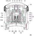
图1是本发明一实施例的采血装置的立体图。图2是图1的采血装置的分解图。请参考图1及图2,本实施例的采血装置100包括采血组件110及穿刺装置120。穿刺装置120包括主体122、架体124、第一弹性件126、穿刺组件128及第二弹性件129。主体122具有限位部1221及第一固持部1222。FIG. 1 is a perspective view of a blood collection device according to an embodiment of the present invention. FIG. 2 is an exploded view of the blood collection device of FIG. 1 . Please refer to FIG. 1 and FIG. 2 , the
图3是图1的采血装置的部分结构立体图。请参考图2及图3,架体124配置于主体122内且具有第二固持部1241。采血组件110可分离地装设于架体124。第一弹性件126配置于主体122与架体124之间,第一固持部1222适于抵抗第一弹性件126的弹性力而将架体124固持于图3所示的第一位置。穿刺组件128配置于主体122内,第二弹性件129配置于穿刺组件128与架体124之间。当架体124位于图1所示的第一位置时,限位部1221限位第二固持部1241,以使第二固持部1241抵抗第二弹性件129的弹性力而将穿刺组件128固持于架体124上。FIG. 3 is a perspective view of a part of the structure of the blood collection device of FIG. 1 . Please refer to FIG. 2 and FIG. 3 , the
图4A及图4B示出图3的采血装置作动。当第一固持部1222释放架体124时,架体124、穿刺组件128、第二弹性件129及采血组件110通过第一弹性件126的弹性力而从图3所示的第一位置移至图4A所示的第二位置,以使采血组件110附着于采血装置100底端处的采血目标(如用户的手)。当架体124位于图4A所示的第二位置时,第二固持部1241脱离限位部1221,穿刺组件128通过第二弹性件129的弹性力而脱离第二固持部1241并如图4B所示往第一位置移动,且架体124适于分离于所述采血目标上的采血组件110。4A and 4B illustrate the operation of the blood sampling device of FIG. 3 . When the
如上所述,本实施例的采血装置100除了可通过第一弹性件126的弹性力使架体124、穿刺组件128、第二弹性件129及采血组件110一起往采血装置100底端处的采血目标击发,更可通过第二弹性件129的弹性力使穿刺组件128在完成击发之后自动地往采血装置100内部复位以分离于采血目标,据以简化采血装置100的操作流程。此外,在架体124、穿刺组件128及采血组件110一起往采血目标击发而使采血组件110的采血针114随着穿刺组件128刺入采血目标之后,采血组件110可附着于采血目标并分离于架体124。藉此,只需要进行一次采血装置100的操作,就能让采血组件110长时间附着于采血目标上持续进行多次采血,而不需在每一次采血都让用户承受被穿刺组件128穿刺的疼痛。另外,本实施例的采血组件110预先装设于穿刺组件120的架体124,故使用者不需自行进行采血组件110与架体124的组装就可直接使用采血装置100。从而,本实施例的采血装置100具有较佳的使用便利性且可增加使用者自行采血的意愿。As described above, in addition to the elastic force of the first
以下具体说明本实施例的采血装置100的各构件的组成及作用方式。The composition and function of each component of the
在本实施例中,穿刺装置120更包括按压件121及第三弹性件123,按压件121配置于主体122,第三弹性件123配置于按压件121与主体122之间。按压件121适于抵抗第三弹性件123的弹性力被用户按压而带动第一固持部1222释放架体124,且按压件121适于通过第三弹性件123的弹性力而复位。在其他实施例中,可利用其他结构及方式来带动第一固持部1222释放架体124,本发明不对此加以限制。In this embodiment, the
更详细而言,本实施例的主体122包括外壳1223、上盖1224及下盖1225。外壳1223容纳限位部1221、第一固持部1222、第一弹性件126、穿刺组件128、第二弹性件129及采血组件110。上盖1224例如是旋盖,其以旋转螺合的方式而固定于外壳1223的顶部,并用以止挡按压件121以避免按压件121脱离主体122。下盖1225例如是旋盖,其以旋转螺合的方式而固定于外壳1223的底部,并用以止挡架体124以避免架体124脱离主体122。In more detail, the
第一固持部1222通过螺锁件S1而固定于外壳1223,且限位部1221通过螺锁件S2而固定于外壳1223及第一固持部1222。其中,第一固持部1222包括本体1222a及至少一勾爪1222b(示出为多个),勾爪1222b连接于本体1222a。本体1222a用以容纳限位部1221。勾爪1222b用以如图3所示勾合于架体124的开槽124a以固持架体124。用户需抵抗第三弹性件123的弹性力及第一固持部1222的勾爪1222b的弹性力以按压按压件121,被按压的按压件121藉其延伸部121a施力于勾爪1222b,使勾爪1222b往本体1222a产生弹性变形而释放架体124。当使用者不再按压按压件121时,按压件121除了通过第三弹性件123的弹性力而往上复位,更通过第一固持部1222的勾爪1222b的弹性力而往上复位。在其他实施例中,可省略第三弹性件123的设置,而仅通过勾爪1222b的弹性力使按压件121往上复位。The
架体124的第二固持部1241包括至少一勾爪1241a(示出为多个)。限位部1221例如是套筒。当架体124位于图3所示的第一位置时,勾爪1241a、穿刺组件128及第二弹性件129位于所述套筒(限位部1221)内,且勾爪1241a被所述套筒(限位部1221)的内壁推抵而勾合于穿刺组件128。承上,所述套筒(限位部1221)具有至少一凹口N1(图2示出为多个),且第一固持部1222的本体1222a具有至少一凹口N2(图2示出为多个)。当架体124如图4A所示位于第二位置时,勾爪1241a对应于凹口N1及凹口N2而被所述套筒(限位部1221)释放,使图4A的穿刺组件128能够通过第二弹性件129的弹性力而将勾爪1241a往外推开并往上移至图4B所示位置。The
穿刺组件128包括主体1281及刺针1282,主体1281位于架体124与限位部1221之间,刺针1282连接于主体1281。采血组件110包括传感器112及前述采血针114,传感器112以卡扣或其他适当方式而可分离地装设于架体124,采血针114连接于传感器112。穿刺组件128的刺针1282穿过架体124及传感器112且至少部分地围绕采血针114。The
刺针1282的硬度大于采血针114的硬度。从而,当架体124、穿刺组件128及采血组件110如图4A所示一起击发而到达第二位置时,刺针1282可刺入采血目标(如用户的手),采血针114随之进入采血目标,且传感器112藉其底部的胶体附着于采血目标的表面。然后,当穿刺组件128通过第二弹性件129的弹性力而如图4B所示往上复位时,刺针1282脱离采血目标且分离于采血针114。传感器112底部的所述胶体与采血目标之间的胶合力例如大于架体124与传感器112之间的结合力,故当图4B所示的传感器112附着于采血目标的表面时,用户只要对穿刺装置120施加往上的力,就可让架体124与传感器112相互脱离,使采血组件110留在采血目标上,持续进行长时间的多次采血。The hardness of the
图5是本发明另一实施例的采血装置的部分构件立体图。图5所示实施例与前述实施例的不同处在于,图5的架体124具有往上延伸的多个勾合部124b,第一固持部1222的勾爪1222b’勾合于勾合部124b。藉此配置方式,勾爪1222b’可具有较短的长度。具体而言,第一固持部1222的本体1222a具有相对的顶端TE及底端BE,底端BE朝向架体124,勾爪1222b’从顶端TE以延伸长度往底端BE延伸,且此延伸长度小于顶端TE与底端BE之间的距离。此外,勾爪1222b’可具有结构补强肋R,以提升勾爪1222b’的结构强度。5 is a perspective view of a part of the components of a blood collection device according to another embodiment of the present invention. The difference between the embodiment shown in FIG. 5 and the previous embodiments is that the
图6是本发明另一实施例的采血装置的部分构件立体图。图6所示实施例与图5所示实施例的不同处在于,图6的勾爪1222b’不具有结构补强肋R。FIG. 6 is a perspective view of a part of components of a blood collection device according to another embodiment of the present invention. The difference between the embodiment shown in FIG. 6 and the embodiment shown in FIG. 5 is that the
综上所述,本发明的采血装置除了可通过第一弹性件的弹性力使架体、穿刺组件、第二弹性件及采血组件一起往采血目标(如用户的手)击发,更可通过第二弹性件的弹性力使穿刺组件在完成击发之后自动地往采血装置内部复位以分离于采血目标,据以简化采血装置的操作流程。此外,在架体、穿刺组件及采血组件一起往采血目标击发而使采血组件的采血针随着穿刺组件刺入采血目标之后,采血组件可附着于采血目标并分离于架体。藉此,只需要进行一次采血装置的操作,就能让采血组件长时间附着于采血目标上持续进行多次采血,而不需在每一次采血都让用户承受被穿刺组件穿刺的疼痛。另外,本发明的采血组件预先装设于穿刺组件的架体,故使用者不需自行进行采血组件与架体的组装就可直接使用采血装置。从而,本发明的采血装置具有较佳的使用便利性且可增加使用者自行采血的意愿。To sum up, in the blood collection device of the present invention, in addition to the elastic force of the first elastic member, the frame body, the puncture assembly, the second elastic member and the blood collection assembly can be fired to the blood collection target (such as the user's hand) together, but also through the first elastic member. The elastic force of the two elastic members makes the puncture assembly automatically reset to the inside of the blood collection device after firing, so as to be separated from the blood collection target, thereby simplifying the operation process of the blood collection device. In addition, after the rack body, the puncture assembly and the blood collection assembly are fired together to the blood collection target so that the blood collection needle of the blood collection assembly penetrates the blood collection target with the puncture assembly, the blood collection assembly can be attached to the blood collection target and separated from the rack body. In this way, only one operation of the blood collection device is required, and the blood collection assembly can be attached to the blood collection target for a long time to continuously perform multiple blood collections without causing the user to suffer the pain of being punctured by the puncture assembly every time the blood is collected. In addition, the blood collection assembly of the present invention is pre-installed on the frame of the puncture assembly, so the user can directly use the blood collection device without assembling the blood collection assembly and the frame by himself. Therefore, the blood collection device of the present invention has better convenience of use and can increase the willingness of the user to collect blood by himself.
最后应说明的是:以上各实施例仅用以说明本发明的技术方案,而非对其限制;尽管参照前述各实施例对本发明进行了详细的说明,本领域的普通技术人员应当理解:其依然可以对前述各实施例所记载的技术方案进行修改,或者对其中部分或者全部技术特征进行等同替换;而这些修改或者替换,并不使相应技术方案的本质脱离本发明各实施例技术方案的范围。Finally, it should be noted that the above embodiments are only used to illustrate the technical solutions of the present invention, but not to limit them; although the present invention has been described in detail with reference to the foregoing embodiments, those of ordinary skill in the art should understand that: The technical solutions described in the foregoing embodiments can still be modified, or some or all of the technical features thereof can be equivalently replaced; and these modifications or replacements do not make the essence of the corresponding technical solutions deviate from the technical solutions of the embodiments of the present invention. scope.
Claims (20)
Applications Claiming Priority (2)
| Application Number | Priority Date | Filing Date | Title |
|---|---|---|---|
| US202063055338P | 2020-07-23 | 2020-07-23 | |
| US63/055,338 | 2020-07-23 |
Publications (2)
| Publication Number | Publication Date |
|---|---|
| CN113967016Atrue CN113967016A (en) | 2022-01-25 |
| CN113967016B CN113967016B (en) | 2024-04-12 |
Family
ID=79586366
Family Applications (1)
| Application Number | Title | Priority Date | Filing Date |
|---|---|---|---|
| CN202110839694.8AActiveCN113967016B (en) | 2020-07-23 | 2021-07-23 | Puncture device and blood collection device |
Country Status (3)
| Country | Link |
|---|---|
| US (1) | US20220022787A1 (en) |
| CN (1) | CN113967016B (en) |
| TW (1) | TWI780828B (en) |
Cited By (1)
| Publication number | Priority date | Publication date | Assignee | Title |
|---|---|---|---|---|
| WO2025145429A1 (en)* | 2024-01-05 | 2025-07-10 | 深圳华大智造科技股份有限公司 | Body fluid sampling apparatus and method |
Citations (9)
| Publication number | Priority date | Publication date | Assignee | Title |
|---|---|---|---|---|
| TW200714259A (en)* | 2005-06-30 | 2007-04-16 | Bayer Healthcare Llc | Single-puncture lancing system |
| JP2010227437A (en)* | 2009-03-27 | 2010-10-14 | Nipro Corp | Disposable blood collection device |
| KR101208479B1 (en)* | 2012-06-19 | 2012-12-05 | 장영주 | Blood lancet device |
| CN103211602A (en)* | 2012-01-19 | 2013-07-24 | 华广生技股份有限公司 | Puncture device |
| CN106419934A (en)* | 2016-11-08 | 2017-02-22 | 苏州施莱医疗器械有限公司 | Disposable hemostix capable of preventing secondary puncturing |
| TWM546204U (en)* | 2017-04-17 | 2017-08-01 | Ming Chuan Univ | Needling depth adjustment structure of lancing device |
| CN110464363A (en)* | 2019-07-25 | 2019-11-19 | 淮安市天达医疗器械有限公司 | Reduce the blood collecting pen for puncturing pain |
| CN110996775A (en)* | 2017-06-23 | 2020-04-10 | 德克斯康公司 | Transdermal analyte sensor, applicator therefor, and related methods |
| CN111419246A (en)* | 2020-03-26 | 2020-07-17 | 天津华鸿科技股份有限公司 | Blood sampling pen |
Family Cites Families (6)
| Publication number | Priority date | Publication date | Assignee | Title |
|---|---|---|---|---|
| US5964718A (en)* | 1997-11-21 | 1999-10-12 | Mercury Diagnostics, Inc. | Body fluid sampling device |
| US8425547B2 (en)* | 2003-03-10 | 2013-04-23 | Owen Mumford Limited | Disposable skin pricker |
| US9788771B2 (en)* | 2006-10-23 | 2017-10-17 | Abbott Diabetes Care Inc. | Variable speed sensor insertion devices and methods of use |
| LT3622883T (en)* | 2010-03-24 | 2021-08-25 | Abbott Diabetes Care, Inc. | Medical device inserters and processes of inserting and using medical devices |
| EP2829288B1 (en)* | 2012-03-23 | 2018-08-15 | Nipro Corporation | Connection device and blood component separation apparatus |
| WO2015062845A1 (en)* | 2013-10-31 | 2015-05-07 | Novo Nordisk A/S | Injection device with a needle cannula |
- 2021
- 2021-07-22USUS17/382,355patent/US20220022787A1/enactivePending
- 2021-07-22TWTW110126910Apatent/TWI780828B/enactive
- 2021-07-23CNCN202110839694.8Apatent/CN113967016B/enactiveActive
Patent Citations (9)
| Publication number | Priority date | Publication date | Assignee | Title |
|---|---|---|---|---|
| TW200714259A (en)* | 2005-06-30 | 2007-04-16 | Bayer Healthcare Llc | Single-puncture lancing system |
| JP2010227437A (en)* | 2009-03-27 | 2010-10-14 | Nipro Corp | Disposable blood collection device |
| CN103211602A (en)* | 2012-01-19 | 2013-07-24 | 华广生技股份有限公司 | Puncture device |
| KR101208479B1 (en)* | 2012-06-19 | 2012-12-05 | 장영주 | Blood lancet device |
| CN106419934A (en)* | 2016-11-08 | 2017-02-22 | 苏州施莱医疗器械有限公司 | Disposable hemostix capable of preventing secondary puncturing |
| TWM546204U (en)* | 2017-04-17 | 2017-08-01 | Ming Chuan Univ | Needling depth adjustment structure of lancing device |
| CN110996775A (en)* | 2017-06-23 | 2020-04-10 | 德克斯康公司 | Transdermal analyte sensor, applicator therefor, and related methods |
| CN110464363A (en)* | 2019-07-25 | 2019-11-19 | 淮安市天达医疗器械有限公司 | Reduce the blood collecting pen for puncturing pain |
| CN111419246A (en)* | 2020-03-26 | 2020-07-17 | 天津华鸿科技股份有限公司 | Blood sampling pen |
Cited By (1)
| Publication number | Priority date | Publication date | Assignee | Title |
|---|---|---|---|---|
| WO2025145429A1 (en)* | 2024-01-05 | 2025-07-10 | 深圳华大智造科技股份有限公司 | Body fluid sampling apparatus and method |
Also Published As
| Publication number | Publication date |
|---|---|
| US20220022787A1 (en) | 2022-01-27 |
| TW202203991A (en) | 2022-02-01 |
| TWI780828B (en) | 2022-10-11 |
| CN113967016B (en) | 2024-04-12 |
Similar Documents
| Publication | Publication Date | Title |
|---|---|---|
| EP1374770B2 (en) | Sensor with integrated lancet | |
| CN100348155C (en) | Piercing assembly, extraction tool for piercing parts and piercing device | |
| US20040248312A1 (en) | Sensor with integrated lancet | |
| JP2007521122A (en) | Braking and telescopic mechanism for lancing device | |
| US20080167673A1 (en) | Lancet Release Mechanism | |
| KR102557857B1 (en) | Applicator for continuous glucose monitoring system | |
| EP2658449B1 (en) | Handheld medical diagnostic devices with sample transfer | |
| WO2021222805A1 (en) | Vacuum generation devices and methods | |
| EP2408371B1 (en) | Modified lancet carrier for single-use lancet sensor assembly | |
| CN113967016A (en) | Puncture device and blood collection device | |
| CN205620428U (en) | blood glucose meter | |
| EP4217737A1 (en) | Test strip ejector for medical device | |
| EP2658447B1 (en) | Handheld medical diagnostic devices | |
| CN201578251U (en) | Lancet | |
| JP2010509589A (en) | Test sensor cartridge | |
| KR20240107624A (en) | Sensor applicator assembly for blood glucose meter |
Legal Events
| Date | Code | Title | Description |
|---|---|---|---|
| PB01 | Publication | ||
| PB01 | Publication | ||
| SE01 | Entry into force of request for substantive examination | ||
| SE01 | Entry into force of request for substantive examination | ||
| GR01 | Patent grant | ||
| GR01 | Patent grant |