CN113933265B - Speckle measuring device and measurement analysis method - Google Patents
Speckle measuring device and measurement analysis methodDownload PDFInfo
- Publication number
- CN113933265B CN113933265BCN202111136209.7ACN202111136209ACN113933265BCN 113933265 BCN113933265 BCN 113933265BCN 202111136209 ACN202111136209 ACN 202111136209ACN 113933265 BCN113933265 BCN 113933265B
- Authority
- CN
- China
- Prior art keywords
- speckle
- enters
- diaphragm
- light
- measurement
- Prior art date
- Legal status (The legal status is an assumption and is not a legal conclusion. Google has not performed a legal analysis and makes no representation as to the accuracy of the status listed.)
- Active
Links
Images
Classifications
- G—PHYSICS
- G01—MEASURING; TESTING
- G01N—INVESTIGATING OR ANALYSING MATERIALS BY DETERMINING THEIR CHEMICAL OR PHYSICAL PROPERTIES
- G01N21/00—Investigating or analysing materials by the use of optical means, i.e. using sub-millimetre waves, infrared, visible or ultraviolet light
- G01N21/17—Systems in which incident light is modified in accordance with the properties of the material investigated
- G01N21/47—Scattering, i.e. diffuse reflection
- G01N21/4738—Diffuse reflection, e.g. also for testing fluids, fibrous materials
- G01N21/474—Details of optical heads therefor, e.g. using optical fibres
Landscapes
- Physics & Mathematics (AREA)
- Health & Medical Sciences (AREA)
- Life Sciences & Earth Sciences (AREA)
- Chemical & Material Sciences (AREA)
- Analytical Chemistry (AREA)
- Biochemistry (AREA)
- General Health & Medical Sciences (AREA)
- General Physics & Mathematics (AREA)
- Immunology (AREA)
- Pathology (AREA)
- Investigating Or Analysing Materials By Optical Means (AREA)
Abstract
Translated fromChinese
Description
Translated fromChinese技术领域technical field
本发明涉及光学检测技术领域,具体涉及一种散斑测量装置及测量分析方法。The invention relates to the technical field of optical detection, in particular to a speckle measurement device and a measurement and analysis method.
背景技术Background technique
激光散斑效应是一种非常有用的物理现象,已广泛用于生物医学应用中。激光散斑是一种只能用统计方法描述的随机散射现象。当相干光被所用波长范围内的粗糙表面反射时,就会发生这种效应。这种效果的特征是由暗点和亮点组成的颗粒状视觉图案。利用散斑分析,可以有效获得待测物体表面的微观形貌,可对微米级的表面形貌进行测量。同时,散斑测量的过程中依旧存在光子与物质的相互作用,可对待测样本中的某些官能团进行分析(如血红蛋白对532nm光子的强烈吸收作用),利用光学干涉过程,表征物体内部的围观特征。同时,在种子筛选领域,利用散斑成像可以有效获得表皮组织的排列信息,通过该信息,可以有效分析种子的含水量以及活性。类似的方法也可以用于对于粮食贮藏过程的监控。在生物医疗方面,本发明可实现原位的辅助诊断,利用散斑成像,可辅助医生对癌变组织切缘进行分析判定,减少由于疲劳与主观造成的误诊。在热带水果保鲜方面,可以监控热带水果表面由于氧化与水分流失所造成的微结构。Laser speckle effect is a very useful physical phenomenon that has been widely used in biomedical applications. Laser speckle is a random scattering phenomenon that can only be described by statistical methods. This effect occurs when coherent light is reflected by rough surfaces in the wavelength range used. This effect is characterized by a grainy visual pattern composed of dark and bright spots. Using speckle analysis, the microscopic topography of the surface of the object to be measured can be effectively obtained, and the surface topography at the micron level can be measured. At the same time, there is still the interaction between photons and substances in the process of speckle measurement, which can analyze some functional groups in the sample to be tested (such as the strong absorption of 532nm photons by hemoglobin), and use the optical interference process to characterize the onlookers inside the object. feature. At the same time, in the field of seed screening, using speckle imaging can effectively obtain the arrangement information of epidermal tissue, and through this information, the water content and activity of seeds can be effectively analyzed. A similar method can also be used to monitor the grain storage process. In terms of biomedicine, the present invention can realize in-situ auxiliary diagnosis, and use speckle imaging to assist doctors in analyzing and judging cancerous tissue margins, reducing misdiagnosis due to fatigue and subjectivity. In terms of tropical fruit preservation, it can monitor the microstructure of tropical fruit surface due to oxidation and water loss.
激光散斑效应在实践中有着大量的应用,但现有技术中的散斑图像进行处理不能够进行实时测量,且进行大尺寸的散斑测量时设备较大,光路搭建困难。The laser speckle effect has a large number of applications in practice, but the speckle image processing in the prior art cannot be measured in real time, and the equipment for large-scale speckle measurement is relatively large, and it is difficult to build an optical path.
发明内容Contents of the invention
本发明克服现有技术的不足,本发明提供一种散斑测量装置及测量分析方法。The invention overcomes the shortcomings of the prior art, and provides a speckle measurement device and a measurement and analysis method.
一种散斑测量装置,包括:出射校正模块、散斑测量模块、数据处理模块。A speckle measurement device, comprising: an emission correction module, a speckle measurement module, and a data processing module.
出射校正模块包括依次沿光路方向设置的光源、空间光调制器、第一平面反射镜。The emission correction module includes a light source, a spatial light modulator, and a first plane reflector sequentially arranged along the direction of the optical path.
散斑测量模块包括依次沿光路方向设置的第一光阑、第一透镜、第二光阑、五棱镜扫描单元、光电探测器。The speckle measurement module includes a first aperture, a first lens, a second aperture, a pentaprism scanning unit, and a photodetector sequentially arranged along the direction of the optical path.
光源发出的光束进入空间光调制器进行调制后,入射至第一平面反射镜,经反射后入射至待测物,经待测物反射后入射至第一光阑,光束穿过第一光阑后入射至第一透镜,经第一透镜入射至第二光阑,光束穿过第二光阑后入射至五棱镜扫描单元,经五棱镜扫描单元出射的光束入射至光电探测器,在光电探测器上形成散斑信号。The light beam emitted by the light source enters the spatial light modulator for modulation, enters the first plane reflector, is reflected and then enters the object to be measured, and then enters the first aperture after being reflected by the object to be measured, and the beam passes through the first aperture Then enter the first lens, enter the second aperture through the first lens, and enter the pentaprism scanning unit after passing through the second aperture. The beam exiting the pentaprism scanning unit enters the photodetector, and the A speckle signal is formed on the device.
数据处理模块接收光电探测器形成的散斑信号进行散斑图像对比度计算、波前结构函数分析、子孔径拼接处理、散斑图像偏振态分析、流体分析。The data processing module receives the speckle signal formed by the photodetector to perform speckle image contrast calculation, wavefront structure function analysis, sub-aperture splicing processing, speckle image polarization state analysis, and fluid analysis.
进一步地,出射校正模块还包括光源整合单元。Further, the emission correction module further includes a light source integration unit.
光源整合单元包括依次沿光路方向设置的第二透镜、滤光片、第三光阑、物镜、第二平面反射镜、第四光阑、可变衰减片。The light source integration unit includes a second lens, a filter, a third aperture, an objective lens, a second plane mirror, a fourth aperture, and a variable attenuation sheet arranged sequentially along the direction of the optical path.
光源发出的光束入射至第二透镜准直后,入射至滤光片进行滤光,经滤光后进入第三光阑,穿过第三光阑入射至物镜进行色散后,入射至第二平面反射镜,经第二平面反射镜反射至第四光阑,穿过第四光阑入射至可变衰减片,经可变衰减片进行衰减后入射至空间光调制器。The light beam emitted by the light source is incident on the second lens and collimated, and then enters the filter for filtering. After filtering, it enters the third aperture, passes through the third aperture, enters the objective lens for dispersion, and then enters the second plane. The reflecting mirror is reflected by the second plane reflecting mirror to the fourth diaphragm, passes through the fourth diaphragm and enters the variable attenuation sheet, and is attenuated by the variable attenuation sheet before entering the spatial light modulator.
进一步地,光源为可调谐、多波长激光光源。Further, the light source is a tunable, multi-wavelength laser light source.
进一步地,光源为不同轨道角动量的涡旋光。Further, the light source is vortex light with different orbital angular momentum.
进一步地,散斑测量模块还包括与第一光阑固定连接的二维位移台,二维位移台用于带动第一光阑移动。Further, the speckle measurement module further includes a two-dimensional displacement stage fixedly connected with the first aperture, and the two-dimensional displacement stage is used to drive the first aperture to move.
一种斑测量分析方法,在光电探测器上形成散斑信号,光电探测器将形成的散斑信号传送至数据处理模块进行散斑图像对比度分析。A speckle measurement and analysis method, in which a speckle signal is formed on a photodetector, and the photodetector transmits the formed speckle signal to a data processing module for speckle image contrast analysis.
归一化的时间自相关函数的光场如公式(1)所示:The light field of the normalized temporal autocorrelation function is shown in formula (1):

其中,E(t)表示t时刻的光场,E*表示光场的复共轭,τ表示自相关延迟时间和平均时间;Among them, E(t) represents the light field at time t, E* represents the complex conjugate of the light field, and τ represents the autocorrelation delay time and average time;
归一化的时间自相关函数的光场的强度如公式(2)所示:The intensity of the light field of the normalized time autocorrelation function is shown in formula (2):

其中,I(t)表示t时刻的光场,τ表示自相关延迟时间和平均时间;二阶自相关函数与一阶自相关函数的函数如公式(3)所示:Among them, I(t) represents the light field at time t, and τ represents the autocorrelation delay time and average time; the function of the second-order autocorrelation function and the first-order autocorrelation function is shown in formula (3):
g2(τ)=1+β|g1(τ)|2 (3)g2 (τ)=1+β|g1 (τ)|2 (3)
其中,β≤1,β表示归一化常数;Among them, β≤1, β represents the normalization constant;
散斑对比度需要在一段积分时间内进行分析,自相关函数与光电探测器曝光时间建立散斑对比度,如公式(4)所示:The speckle contrast needs to be analyzed within a period of integration time, and the speckle contrast is established by the autocorrelation function and the photodetector exposure time, as shown in formula (4):

其中,T表示曝光时间。Among them, T represents the exposure time.
一种斑测量分析方法,A speckle measurement analysis method,
旋转五棱镜扫描单元,使用光电探测器进行散斑信号采集,光电探测器将采集的散斑信号传送至数据处理模块进行波前结构函数分析,波前的结构函数Dwavefront,如公式(5)所示:The rotating pentaprism scanning unit uses a photodetector to collect speckle signals, and the photodetector transmits the collected speckle signals to the data processing module for wavefront structure function analysis. The wavefront structure function Dwavefront is shown in formula (5) Shown:

其中,φ表示检测所得到的波前相位,

与现有技术相比,本发明的有益效果为:Compared with prior art, the beneficial effect of the present invention is:
1、本发明所提供的散斑测量装置及测量分析方法能够实现实时测量待测物的散斑;1. The speckle measurement device and measurement analysis method provided by the present invention can realize real-time measurement of the speckle of the object to be measured;
2、本发明所提供的散斑测量装置及测量分析方法通过设置二位移动台能够测量大尺寸的待测物的散斑;2. The speckle measurement device and measurement analysis method provided by the present invention can measure the speckle of a large-sized object to be measured by setting a two-position mobile station;
3、本发明所提供的散斑测量装置及测量分析方法能够准确计算散斑的对比度。3. The speckle measurement device and measurement and analysis method provided by the present invention can accurately calculate the contrast of the speckle.
附图说明Description of drawings
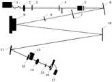
图1是本发明实施例中的散斑测量装置的结构图。FIG. 1 is a structural diagram of a speckle measurement device in an embodiment of the present invention.
其中的附图标记如下:Wherein the reference signs are as follows:
光源1、第二透镜2、滤光片3、第三光阑4、物镜5、第二平面反射镜6、第四光阑7、可变衰减片8、空间光调制器9、第一平面反射镜10、待测物11、第一光阑12、二维位移台13、第一透镜14、第二光阑15、五棱镜扫描单元16、光电探测器17。Light source 1,
具体实施方式detailed description
下面结合附图和实施例对本发明的实施方式作进一步详细描述。需要说明的是,在不冲突的情况下,本发明中的实施例及实施例中的特征可以相互结合。基于本发明中的实施例,本领域普通技术人员在没有作出创造性劳动前提下所获得的所有其他实施例,都属于本发明保护的范围。Embodiments of the present invention will be further described in detail below in conjunction with the accompanying drawings and examples. It should be noted that, in the case of no conflict, the embodiments of the present invention and the features in the embodiments can be combined with each other. Based on the embodiments of the present invention, all other embodiments obtained by persons of ordinary skill in the art without creative efforts fall within the protection scope of the present invention.
图1示出了本发明实施例中的散斑测量装置的结构图。Fig. 1 shows a structural diagram of a speckle measurement device in an embodiment of the present invention.
实施例1:Example 1:
本发明实施例1提供一种散斑测量装置,包括:出射校正模块、散斑测量模块、数据处理模块;出射校正模块包括依次沿光路方向设置的光源1、空间光调制器9、第一平面反射镜10;散斑测量模块依次沿光路方向设置的第一光阑12、第一透镜14、第二光阑15、五棱镜扫描单元16、光电探测器17;光源1发出的光束进入空间光调制器9进行调制后,入射至第一平面反射镜10,经反射后入射至待测物11,经待测物11反射后入射至第一光阑12,光束穿过第一光阑12后入射至第一透镜14,经第一透镜14入射至第二光阑15,光束穿过第二光阑15后入射至五棱镜扫描单元16,经五棱镜扫描单元16出射的光束入射至光电探测器17,在光电探测器17上形成散斑信号;数据处理模块接收光电探测器17形成的散斑信号进行散斑图像对比度计算、波前结构函数分析、子孔径拼接处理、散斑图像偏振态分析、流体分析。Embodiment 1 of the present invention provides a speckle measurement device, including: an emission correction module, a speckle measurement module, and a data processing module; the emission correction module includes a light source 1, a
校正的原理是:散斑测量装置自身会产生像差,散斑测量装置的像差本身如果不做处理,会影响最终待测物11的散斑测量。因此把待测物11替换为反射镜或反射板进行测试,获得散斑测量装置自身产生的像差,在探测器处会形成散斑测量装置自身产生的像差信号,将像差信号传送至数据处理模块。进行待测物11散斑测量时,数据处理模块将校正时获取的像差信号进行去除,通过数据处理的方式去除散斑测量装置自身会产生的像差的干扰。The principle of the correction is that the speckle measurement device itself produces aberrations, and if the aberrations of the speckle measurement device are not dealt with, it will affect the speckle measurement of the final object 11 to be measured. Therefore, the object under test 11 is replaced by a reflector or a reflector for testing to obtain the aberration generated by the speckle measurement device itself, and the aberration signal generated by the speckle measurement device itself will be formed at the detector, and the aberration signal will be transmitted to Data processing module. When performing speckle measurement on the object under test 11 , the data processing module removes the aberration signal obtained during calibration, and removes the aberration interference generated by the speckle measurement device itself through data processing.
本发明实施例1提供一种优选方案,出射校正模块还包括光源1整合单元;包括依次沿光路方向设置的第二透镜2、滤光片3、第三光阑4、物镜5、第二平面反射镜6、第四光阑7、可变衰减片8;光源1发出的光束入射至第二透镜2准直后,入射至滤光片3进行滤光,经滤光后进入第三光阑4,穿过第三光阑4入射至物镜5进行色散后,入射至第二平面反射镜6,经第二平面反射镜6反射至第四光阑7,穿过第四光阑7入射至可变衰减片8,经可变衰减片8进行衰减后入射至空间光调制器9。Embodiment 1 of the present invention provides a preferred solution. The emission correction module also includes an integration unit of a light source 1; including a
根据待测物11的不同,待测物11的反射率也不相同,因此在探测器所接收到的光束的散斑信号的强弱就不同,可变衰减片8根据待测物11反射率与探测器所接收的散斑信号的强弱来控制衰减,以实现多种类待测物11的散斑测量。光源1整合单元能够有效提高光电转换效率,有效提高散斑检测的范围,提高动态响应范围。According to the difference of the object 11 to be measured, the reflectivity of the object 11 to be measured is also different, so the intensity of the speckle signal of the light beam received by the detector is different. The attenuation is controlled according to the intensity of the speckle signal received by the detector, so as to realize speckle measurement of various types of objects 11 to be measured. The integration unit of the light source 1 can effectively improve the photoelectric conversion efficiency, effectively increase the range of speckle detection, and improve the dynamic response range.
本发明实施例1提供一种优选方案,光源1为可调谐、多波长光源1。Embodiment 1 of the present invention provides a preferred solution, and the light source 1 is a tunable, multi-wavelength light source 1 .
光源1发出不同波长的光束进行散斑测量,可针对不同尺度的起伏与微表面形貌的待测物11进行测量,光源1同时发出两种不同波长的复合光束进行测量时,可用差动的方式获得更大的测量动态范围。Light source 1 emits beams of different wavelengths for speckle measurement, which can be used to measure objects 11 with different scales of fluctuations and micro-surface topography. When light source 1 simultaneously emits two composite beams of different wavelengths for measurement, a differential way to obtain a larger measurement dynamic range.
本发明实施例1提供一种优选方案,散斑测量模块还包括与第一光阑12固定连接的二维位移台13,二维位移台13用于带动第一光阑12移动。Embodiment 1 of the present invention provides a preferred solution. The speckle measurement module further includes a two-
二维位移台13带动第一光阑12移动,可实现在使用小面积光电探测器17就采集大口径待测物11散斑,实现大口径待测物11散斑测量,二维位移台13每移动一个位置光电探测器17就可以采集大口径待测物11散斑的一部分,通过数据处理模块进行子孔径散斑信号拼接处理,以实现整体待测物11散斑信息的测量。The two-
实施例2:Example 2:
本发明实施例2提供一种散斑测量装置的测量分析方法,在光电探测器17上形成散斑信号,光电探测器17将形成的散斑信号传送至数据处理模块进行散斑图像对比度分析,
归一化的时间自相关函数与光场的关系,如公式(1)所示:The relationship between the normalized time autocorrelation function and the light field is shown in formula (1):

其中,E(t)表示t时刻的光场,E*表示光场的复共轭,τ表示自相关延迟时间和平均时间;其中延迟时间和平均时间相等。Among them, E(t) represents the light field at time t, E* represents the complex conjugate of the light field, and τ represents the autocorrelation delay time and average time; where the delay time and average time are equal.
归一化的时间自相关函数与光场的强度的关系,如公式(2)所示:The relationship between the normalized time autocorrelation function and the intensity of the light field is shown in formula (2):

其中,I(t)表示t时刻的光场,τ表示自相关延迟时间和平均时间;二阶自相关函数与一阶自相关函数的函数如公式(3)所示:Among them, I(t) represents the light field at time t, and τ represents the autocorrelation delay time and average time; the function of the second-order autocorrelation function and the first-order autocorrelation function is shown in formula (3):
g2(τ)=1+β|g1(τ)|2 (3)g2 (τ)=1+β|g1 (τ)|2 (3)
其中,β≤1,β表示归一化常数,β是由于缺乏光稳定性和由于光电探测器17的空间混叠而导致的斑点平均。where β≤1, β denotes a normalization constant, and β is spot averaging due to lack of photostability and due to spatial aliasing of
散斑对比度需要在一段积分时间内进行分析,自相关函数与光电探测器17曝光时间建立散斑对比度,如公式(4)所示:The speckle contrast needs to be analyzed within a period of integration time, and the speckle contrast is established by the autocorrelation function and the exposure time of the

其中,T表示曝光时间。Among them, T represents the exposure time.
当存在静电散射体时,到达光电探测器17的是散射的光子之和,散射的光子由静态粒子和由动态粒子散射组成:When an electrostatic scatterer is present, what reaches the
E(t)=Ed(t)+ES (5)E(t)=Ed (t)+ES (5)
其中,Ed(t)表示动态散射的光电子的光场,ES表示静态光场散射的光电子的光场。where Ed (t) represents the light field of photoelectrons scattered dynamically, and ES represents the light field of photoelectrons scattered by static light field.
因此,归一化的时间自相关函数的光场的强度还可以表示为公式(6):Therefore, the intensity of the light field of the normalized temporal autocorrelation function can also be expressed as formula (6):
g2(τ)=1+β[(1-ρ)2|g1d(τ)|2+2ρ(1-ρ)|g1d(τ)|+ρ2] (6)g2 (τ)=1+β[(1-ρ)2 |g1d (τ)|2 +2ρ(1-ρ)|g1d (τ)|+ρ2 ] (6)
其中,g1d(τ)表示τ时刻的光场自相关函数,ρ表示静光场散射的光光场粒子的比例,如公式(7)所示:Among them, g1d (τ) represents the light field autocorrelation function at time τ, and ρ represents the proportion of light field particles scattered by the static light field, as shown in formula (7):
ρ=Is/Is+Id (7)ρ=Is /Is +Id (7)
其中,Is表示静态光场散射的光电子的光场的强度,Id表示动态光场散射的光电子的光场。where Is represents the intensity of the light field of photoelectrons scattered by the static light field, andId represents the light field of the photoelectrons scattered by the dynamic light field.
归一化的时间自相关函数与光场的强度的关系,取决于动态散射的光电子的光场的自相关函数;由于静光场为常数,不取决于静态散射的光电子的光场的自相关函数。其自相关函数对于所有延迟值(τ)根据Siegert定理,整理公式(3)可得公式(8)The relationship between the normalized time autocorrelation function and the intensity of the light field depends on the autocorrelation function of the light field of the dynamically scattered photoelectron; since the static light field is constant, it does not depend on the autocorrelation of the light field of the statically scattered photoelectron function. Its autocorrelation function is for all delay values (τ) according to Siegert's theorem, and the formula (3) can be sorted out to get the formula (8)
g1m(τ)=(1-ρ)|g1d(τ)|+ρ (8)g1m (τ)=(1-ρ)|g1d (τ)|+ρ (8)
将公式(8)代入公式(5),可得到公式(9):Substituting formula (8) into formula (5), formula (9) can be obtained:

动态散射的光电子的光场的自相关函数作为指数衰减(洛伦兹分布),如公式(10)所示:The autocorrelation function of the light field of the dynamically scattered photoelectrons as an exponential decay (Lorentz distribution), as shown in formula (10):

其中,x=T/τc;Among them, x=T/τc;
经高斯分布修正的自相关函数,如公式(11)所示:The autocorrelation function corrected by Gaussian distribution, as shown in formula (11):

实施例3:Example 3:
本发明实施例3提供一种散斑测量装置的测量分析方法。
旋转五棱镜扫描单元16,使用光电探测器17进行散斑信号采集,光电探测器17将采集的散斑信号传送至数据处理模块进行波前结构函数分析,波前的结构函数Dwavefront,如公式(12)所示:The rotating

其中,φ表示检测所得到的波前相位,

实施例4:Example 4:
本发明实施例4提供一种散斑测量装置的测量分析方法。Embodiment 4 of the present invention provides a measurement and analysis method of a speckle measurement device.
通过移动二维位移台13,可以对大口径待测物11的散斑进行采集,二维位移台13每移动一个位置光电探测器17就可以采集大口径待测物11散斑的一部分,通过数据处理模块进行子孔径散斑信号拼接处理,以实现整体待测物11散斑信息的测量。By moving the two-
首先考虑两个子孔径拼接的情况,设定其中一个为“基准子孔径”,另一个为“拼接子孔径”。两个子孔径是指移动二维位移台两次所采集的两次的散斑信号。First consider the case of splicing two sub-apertures, and set one of them as a "reference sub-aperture" and the other as a "stitched sub-aperture". The two sub-apertures refer to two speckle signals collected by moving the two-dimensional stage twice.
假设两个子孔径的位置已经大体对准,利用二者重叠区域数据的差值,可以估计被拼接子孔径的刚体位移,其表达式如所示Assuming that the positions of the two sub-apertures have been roughly aligned, the rigid body displacement of the spliced sub-apertures can be estimated by using the difference of the data in the overlapping area of the two, and its expression is shown as

其中,P表示平移的系数,Tx、Ty分别表示二维位移台13在X方向和Y方向的倾斜量,Sx、Sy分别表示子孔径之间的相互错开,R代表子孔径之间的相对旋转,n代表中高频误差。如果使用最小二乘法,需要n为服从高斯分布的误差,才可以得到参数的无偏一致估计,如果误差统计特性偏离高斯分布较多可使用极大似然估计的方法。在子孔径拼接前需要综合分析子孔径的大小与采样方式,保证每个子孔径中具有足够多的散斑。采用极大似然估计,对不同子孔径之间的相对误差进行分析。Among them, P represents the coefficient of translation, Tx ,Ty represent the inclination of the two-
在本说明书的描述中,参考术语“一个实施例”、“一些实施例”、“示例”、“具体示例”、或“一些示例”等的描述意指结合该实施例或示例描述的具体特征、结构、材料或者特点包含于本发明的至少一个实施例或示例中。在本说明书中,对上述术语的示意性表述不必须针对的是相同的实施例或示例。而且,描述的具体特征、结构、材料或者特点可以在任一个或多个实施例或示例中以合适的方式结合。此外,在不相互矛盾的情况下,本领域的技术人员可以将本说明书中描述的不同实施例或示例以及不同实施例或示例的特征进行结合和组合。In the description of this specification, descriptions referring to the terms "one embodiment", "some embodiments", "example", "specific examples", or "some examples" mean that specific features described in connection with the embodiment or example , structure, material or characteristic is included in at least one embodiment or example of the present invention. In this specification, the schematic representations of the above terms are not necessarily directed to the same embodiment or example. Furthermore, the described specific features, structures, materials or characteristics may be combined in any suitable manner in any one or more embodiments or examples. In addition, those skilled in the art can combine and combine different embodiments or examples and features of different embodiments or examples described in this specification without conflicting with each other.
尽管上面已经示出和描述了本发明的实施例,可以理解的是,上述实施例是示例性的,不能理解为对本发明的限制。本领域的普通技术人员在本发明的范围内可以对上述实施例进行变化、修改、替换和变型。Although the embodiments of the present invention have been shown and described above, it should be understood that the above embodiments are exemplary and should not be construed as limitations on the present invention. Those skilled in the art can make changes, modifications, substitutions and modifications to the above-mentioned embodiments within the scope of the present invention.
以上本发明的具体实施方式,并不构成对本发明保护范围的限定。任何根据本发明的技术构思所做出的各种其他相应的改变与变形,均应包含在本发明权利要求的保护范围内。The above specific implementation manners of the present invention do not constitute a limitation to the protection scope of the present invention. Any other corresponding changes and modifications made according to the technical concept of the present invention shall be included in the protection scope of the claims of the present invention.
Claims (6)


Priority Applications (1)
| Application Number | Priority Date | Filing Date | Title |
|---|---|---|---|
| CN202111136209.7ACN113933265B (en) | 2021-09-27 | 2021-09-27 | Speckle measuring device and measurement analysis method |
Applications Claiming Priority (1)
| Application Number | Priority Date | Filing Date | Title |
|---|---|---|---|
| CN202111136209.7ACN113933265B (en) | 2021-09-27 | 2021-09-27 | Speckle measuring device and measurement analysis method |
Publications (2)
| Publication Number | Publication Date |
|---|---|
| CN113933265A CN113933265A (en) | 2022-01-14 |
| CN113933265Btrue CN113933265B (en) | 2023-01-03 |
Family
ID=79276988
Family Applications (1)
| Application Number | Title | Priority Date | Filing Date |
|---|---|---|---|
| CN202111136209.7AActiveCN113933265B (en) | 2021-09-27 | 2021-09-27 | Speckle measuring device and measurement analysis method |
Country Status (1)
| Country | Link |
|---|---|
| CN (1) | CN113933265B (en) |
Families Citing this family (1)
| Publication number | Priority date | Publication date | Assignee | Title |
|---|---|---|---|---|
| CN117517261A (en)* | 2024-01-03 | 2024-02-06 | 中国科学院长春光学精密机械与物理研究所 | Multi-frame imaging device through scattering media for optical detection and imaging method thereof |
Citations (3)
| Publication number | Priority date | Publication date | Assignee | Title |
|---|---|---|---|---|
| JP2002365027A (en)* | 2001-06-07 | 2002-12-18 | Japan Science & Technology Corp | Surface observation device |
| US7403290B1 (en)* | 2006-06-30 | 2008-07-22 | Carl Zeiss Smt Ag | Method and means for determining the shape of a rough surface of an object |
| CN212410025U (en)* | 2020-06-03 | 2021-01-26 | 杭州三泰检测技术有限公司 | A laser display speckle measurement device that simulates visual perception |
Family Cites Families (20)
| Publication number | Priority date | Publication date | Assignee | Title |
|---|---|---|---|---|
| US7455407B2 (en)* | 2000-02-11 | 2008-11-25 | Amo Wavefront Sciences, Llc | System and method of measuring and mapping three dimensional structures |
| EP1814362A1 (en)* | 2006-01-30 | 2007-08-01 | Leister Process Technologies | Heating element for a hot air device |
| US8596786B2 (en)* | 2008-09-30 | 2013-12-03 | Carl Zeiss Meditec Ag | Arrangements and method for measuring an eye movement, particularly a movement of the fundus of the eye |
| CN101797149B (en)* | 2009-12-31 | 2012-04-11 | 中国科学院长春光学精密机械与物理研究所 | Liquid crystal adaptive aberration correction retinal imaging device with high-efficiency utilization of energy |
| KR101225561B1 (en)* | 2010-09-07 | 2013-01-24 | 다이니폰 인사츠 가부시키가이샤 | Projection-type footage display device |
| CN102681365B (en)* | 2012-05-18 | 2015-01-14 | 中国科学院光电技术研究所 | Projection objective wave aberration detection device and method |
| JP2014032371A (en)* | 2012-08-06 | 2014-02-20 | Oxide Corp | Speckle contrast generator and speckle contrast evaluation device |
| JP6470273B2 (en)* | 2013-06-19 | 2019-02-13 | ザ ジェネラル ホスピタル コーポレイション | Omnidirectional visual device |
| CN104634285B (en)* | 2015-02-28 | 2017-04-05 | 河南科技大学 | A kind of regulatable speckle generator of contrast value and its production method |
| CN104634699B (en)* | 2015-02-28 | 2017-05-10 | 河南科技大学 | Laguerre-gaussian beam-based speckle contrast imaging measurement device and laguerre-gaussian beam-based speckle contrast imaging measurement method |
| US9541635B2 (en)* | 2015-03-10 | 2017-01-10 | The Boeing Company | Laser phase diversity for beam control in phased laser arrays |
| CN105043543B (en)* | 2015-08-27 | 2017-04-05 | 河南科技大学 | A kind of manufacture method of the super Rayleigh speckle field of controllable |
| EP3446478B1 (en)* | 2016-04-20 | 2022-03-23 | Laser Associated Sciences, Inc. | Systems and methods for calibrating and correcting a speckle contrast flowmeter |
| CN108007677B (en)* | 2017-12-27 | 2023-10-27 | 杭州远方光电信息股份有限公司 | Laser projection speckle measurement system |
| FR3079028B1 (en)* | 2018-03-15 | 2020-05-15 | Horiba France Sas | INSTANTANEOUS ELLIPSOMETER OR SPECTROSCOPIC SCATTEROMETER AND MEASURING METHOD THEREOF |
| US11835733B2 (en)* | 2019-09-16 | 2023-12-05 | California Institute Of Technology | Control light intensity through scattering media with speckle intensity sequencing |
| CN112113514B (en)* | 2020-09-22 | 2021-12-31 | 中国科学院长春光学精密机械与物理研究所 | Method, device and system for detecting wavefront information |
| CN112229847B (en)* | 2020-10-15 | 2025-02-14 | 中国工程物理研究院激光聚变研究中心 | A high-resolution automatic detection device and method for optical element surface defects |
| CN112684460B (en)* | 2020-12-21 | 2024-03-22 | 武汉光目科技有限公司 | Area array sweep frequency measuring device and method |
| CN113391444A (en)* | 2021-06-28 | 2021-09-14 | 中国科学院长春光学精密机械与物理研究所 | Adaptive optical system |
- 2021
- 2021-09-27CNCN202111136209.7Apatent/CN113933265B/enactiveActive
Patent Citations (3)
| Publication number | Priority date | Publication date | Assignee | Title |
|---|---|---|---|---|
| JP2002365027A (en)* | 2001-06-07 | 2002-12-18 | Japan Science & Technology Corp | Surface observation device |
| US7403290B1 (en)* | 2006-06-30 | 2008-07-22 | Carl Zeiss Smt Ag | Method and means for determining the shape of a rough surface of an object |
| CN212410025U (en)* | 2020-06-03 | 2021-01-26 | 杭州三泰检测技术有限公司 | A laser display speckle measurement device that simulates visual perception |
Non-Patent Citations (4)
| Title |
|---|
| Fiber-Optic Point-Based Sensor UsingSpecklegram Measurement;Jiao-JiaoWang;《sensors》;20171217;第17卷(第10期);第1-9页* |
| Quality assessment of speckle patterns for digital image correlation byShannon entropy;Xiao-Yong Liua;《Optik》;20151231;第126卷(第23期);第4206-4211页* |
| 投影辅助的数字剪切散斑干涉扫描检测技术;李欣;《红外与激光工程》;20210831;第50卷(第8期);第20210509-1-8页* |
| 数字散斑干涉图像拼接方法研究;潘淑媛;《仪表技术与传感器》;20210131(第1期);第117-122页* |
Also Published As
| Publication number | Publication date |
|---|---|
| CN113933265A (en) | 2022-01-14 |
Similar Documents
| Publication | Publication Date | Title |
|---|---|---|
| US9546952B2 (en) | Distribution of refractive index measurement by synthetic aperture tomography | |
| US9134110B2 (en) | Phase image acquisition device | |
| EP0592200B1 (en) | Apparatus for measuring optical information in scattering medium and method therefor | |
| US20190005351A1 (en) | Noninvasive, label-free, in vivo flow cytometry using speckle correlation technique | |
| US8687253B2 (en) | Speckle noise reduction based on longitudinal shift of sample | |
| EP2606817A1 (en) | System for reconstructing optical properties of a scattering medium, including a source of pulsed radiation and at least two detectors of two different types, and associated reconstruction method | |
| US20210310787A1 (en) | Method and systems for the non-invasive optical characterization of a heterogeneous medium | |
| CN113331788B (en) | A MFMT-XCT Dual Mode System | |
| CN113933265B (en) | Speckle measuring device and measurement analysis method | |
| US11507020B2 (en) | Optical measurement system for obtaining and analyzing surface topography of object | |
| CN114966739B (en) | Target detection imaging system and method based on fiber laser phased array | |
| CN110702682A (en) | Dark field microscope under interference-scattering enhancement mode | |
| US20250102290A1 (en) | Optical Coherence Tomography System for Subsurface Inspection | |
| US10234268B2 (en) | Method and apparatus for digital holographic microtomography | |
| FR2935803A1 (en) | DEVICE AND METHOD FOR OPTICALLY MEASURING THE TRANSMISSION AND DIFFUSION OF EYE MEDIA | |
| EP0445293A1 (en) | Light receiving system of heterodyne detection and image forming device for light transmission image using said light receiving system | |
| JP2020190459A (en) | Method and device for evaluating cytotoxicity | |
| CN117308813A (en) | Spherical element surface shape reconstruction system and method based on light field diffraction iteration | |
| Knuettel et al. | Analytical modeling of spatial resolution curves in turbid media acquired with optical coherence tomography (OCT) | |
| Mathis et al. | Field experiment performance of the receiver elements for a Fourier telescopy imaging system | |
| Fedosov et al. | Bioflow measuring: laser Doppler and speckle techniques | |
| CN210894137U (en) | Dark field microscope under interference-scattering enhancement mode | |
| JPH02110346A (en) | Morphological and functional imaging device | |
| CN111272110B (en) | Multiple scattering transmitted light angle distribution measuring device based on thin plate medium | |
| Mateen et al. | Results from the laboratory demonstration of the nonlinear curvature wavefront sensor |
Legal Events
| Date | Code | Title | Description |
|---|---|---|---|
| PB01 | Publication | ||
| PB01 | Publication | ||
| SE01 | Entry into force of request for substantive examination | ||
| SE01 | Entry into force of request for substantive examination | ||
| GR01 | Patent grant | ||
| GR01 | Patent grant |