CN113894517B - Automatic screw righting and screwing device based on vision - Google Patents
Automatic screw righting and screwing device based on visionDownload PDFInfo
- Publication number
- CN113894517B CN113894517BCN202010571383.3ACN202010571383ACN113894517BCN 113894517 BCN113894517 BCN 113894517BCN 202010571383 ACN202010571383 ACN 202010571383ACN 113894517 BCN113894517 BCN 113894517B
- Authority
- CN
- China
- Prior art keywords
- screw
- righting
- rod
- clutch
- screwing
- Prior art date
- Legal status (The legal status is an assumption and is not a legal conclusion. Google has not performed a legal analysis and makes no representation as to the accuracy of the status listed.)
- Active
Links
Images

Classifications
- B—PERFORMING OPERATIONS; TRANSPORTING
- B23—MACHINE TOOLS; METAL-WORKING NOT OTHERWISE PROVIDED FOR
- B23P—METAL-WORKING NOT OTHERWISE PROVIDED FOR; COMBINED OPERATIONS; UNIVERSAL MACHINE TOOLS
- B23P19/00—Machines for simply fitting together or separating metal parts or objects, or metal and non-metal parts, whether or not involving some deformation; Tools or devices therefor so far as not provided for in other classes
- B23P19/04—Machines for simply fitting together or separating metal parts or objects, or metal and non-metal parts, whether or not involving some deformation; Tools or devices therefor so far as not provided for in other classes for assembling or disassembling parts
- B23P19/06—Screw or nut setting or loosening machines
- B—PERFORMING OPERATIONS; TRANSPORTING
- B23—MACHINE TOOLS; METAL-WORKING NOT OTHERWISE PROVIDED FOR
- B23P—METAL-WORKING NOT OTHERWISE PROVIDED FOR; COMBINED OPERATIONS; UNIVERSAL MACHINE TOOLS
- B23P19/00—Machines for simply fitting together or separating metal parts or objects, or metal and non-metal parts, whether or not involving some deformation; Tools or devices therefor so far as not provided for in other classes
- B23P19/10—Aligning parts to be fitted together
Landscapes
- Engineering & Computer Science (AREA)
- Mechanical Engineering (AREA)
- Automatic Assembly (AREA)
- Details Of Spanners, Wrenches, And Screw Drivers And Accessories (AREA)
Abstract
Description
Translated fromChinese技术领域technical field
本发明涉及的是一种机器人领域的技术,具体是一种基于视觉的螺钉自动扶正及拧紧装置。The invention relates to a technology in the field of robots, in particular to a vision-based screw automatic righting and tightening device.
背景技术Background technique
采用机器人或者自动拧紧装置拧紧螺钉时,时常出现螺钉初始姿态倾斜,导致自动拧紧机构无法正确与螺钉接触,从而无法拧紧导致功能失效。本本明针对螺钉初始姿态倾斜下需要扶正的作业需求,采用视觉自动识别螺钉的姿态,并通过扶正装置实现螺钉的自动扶正。在此基础上实现自动螺钉拧紧作业。本发明提高了自动拧螺钉作业的成功率,提高了生产效率和质量。When using a robot or an automatic tightening device to tighten a screw, the initial attitude of the screw often tilts, causing the automatic tightening mechanism to fail to contact the screw correctly, resulting in failure to tighten and resulting in functional failure. The present invention aims at the operation requirement of straightening when the initial posture of the screw is inclined, adopts vision to automatically recognize the posture of the screw, and realizes the automatic straightening of the screw through the straightening device. On this basis, the automatic screw tightening operation is realized. The invention improves the success rate of the automatic screw screwing operation, and improves the production efficiency and quality.
发明内容Contents of the invention
本发明针对现有技术存在的上述不足,提出一种基于视觉的螺钉自动扶正及拧紧装置,能够自动识别螺钉倾斜姿态、位置,并通过自动扶正机构对螺钉进行扶正,自动拧紧装置实现自动拧紧的机器人。该装置前部设置于摄像头和光源,可通过几何特征识定位螺钉的位置和姿态,并自动实现扶正并完成螺钉拧紧作业并达到设定的扭矩。本发明适用于任意自动拧螺钉作业中螺钉的扶正。Aiming at the above-mentioned deficiencies in the prior art, the present invention proposes a vision-based screw automatic straightening and tightening device, which can automatically identify the tilted posture and position of the screw, and straighten the screw through the self-righting mechanism, and the automatic tightening device realizes automatic tightening robot. The front part of the device is equipped with a camera and a light source, which can identify the position and posture of the set screw through geometric features, and automatically realize the righting and complete the screw tightening operation to reach the set torque. The invention is applicable to the straightening of screws in any automatic screw screwing operation.
本发明是通过以下技术方案实现的:The present invention is achieved through the following technical solutions:
本发明涉及一种可设置于机器人及任意运动平台上的基于视觉导引的自动拧螺钉及扶正装置,包括:设置于平台框架上方的摄像头和用于提供螺钉拧紧和扶正的动力的拧螺钉及扶正驱动单元以及设置于平台框架下方的拧螺钉结构和用于倾斜未入孔的螺钉的扶正机构,其中:平台框架设置于机器人或者平台的末端,拧螺钉及扶正驱动单元和拧螺钉结构同轴连接,拧螺钉结构和扶正装置相互啮合,摄像头和光源设置于装置前部用于进行螺钉的特征识别并精确定位其位置和姿态,同时可提供被测特征的图像信息给操作人员,拧螺钉结构通过控制驱动电机的力矩模式控制螺钉的拧紧力矩。The present invention relates to a vision-guided automatic screw-tightening and righting device that can be set on a robot and any motion platform, including: a camera set above the platform frame and a screw-tightening and righting device for providing power for screw tightening and righting The righting drive unit and the screwing structure arranged under the platform frame and the righting mechanism for tilting the screws that have not entered the hole, wherein: the platform frame is arranged at the end of the robot or platform, and the screwing and righting drive unit is coaxial with the screwing structure Connection, the screw screw structure and the righting device are engaged with each other, the camera and the light source are set at the front of the device to identify the features of the screw and accurately locate its position and posture, and at the same time provide image information of the measured features to the operator, the screw screw structure The tightening torque of the screw is controlled by controlling the torque mode of the drive motor.
技术效果technical effect
本发明整体解决了现有技术在螺钉倾斜时无法及时扶正导致无法拧紧或拧紧效果较差的问题;The present invention as a whole solves the problem in the prior art that the screw cannot be straightened in time when the screw is tilted, resulting in failure to tighten or poor tightening effect;
与现有技术相比,本发明采用摄像头自动搜索箱内螺钉头的形状特征,并自动调整螺丝刀到螺钉头的中心,采用电机驱动拧紧刀头及压簧实现螺钉头的Z向顺应运动;采用控制伺服电机的电流控制拧紧力矩,从而满足拧螺钉的固定力矩需求;当螺钉发生倾斜时,采用扶正装置实现螺钉的自动扶正。该发明提高了生产效率和质量,提升了自动化和智能化水平。Compared with the prior art, the present invention uses a camera to automatically search the shape characteristics of the screw head in the box, and automatically adjusts the screwdriver to the center of the screw head, and uses a motor to drive the screw head and compression spring to realize the Z-direction compliant movement of the screw head; Control the current of the servo motor to control the tightening torque, so as to meet the fixed torque requirements of the screw; when the screw is tilted, the straightening device is used to realize the automatic straightening of the screw. The invention improves production efficiency and quality, and improves the level of automation and intelligence.
附图说明Description of drawings
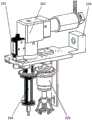
图1为本发明的结构示意图;Fig. 1 is a structural representation of the present invention;
图中:101摄像头、102拧螺钉及扶正驱动单元、103平台框架、104拧螺钉结构、105扶正机构;In the figure: 101 camera, 102 screw and righting drive unit, 103 platform frame, 104 screw structure, 105 righting mechanism;
图2为X向平移及拧螺钉机构图;Figure 2 is a diagram of the mechanism for X-direction translation and screwing;
图中:201连接法兰、202齿轮、203刀座、204导向杆、205压簧、206轴端挡板、207刀杆;In the figure: 201 connecting flange, 202 gear, 203 tool seat, 204 guide rod, 205 pressure spring, 206 shaft end baffle, 207 tool bar;
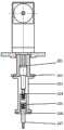
图3为螺钉扶正装置图:Figure 3 is a diagram of the screw righting device:
图中:301第一端盖、302轴承座、303支撑框架、304外套筒、305内套筒、306轴承、307传动杆、308齿轮、309离合器法兰盘、310离合器定子、311离合器动盘、312曲杆、313连杆、314扶正执行器、315连接板、316离合器传动轴、317第二端盖、318轴承盖、319轴承、320螺杆、321中心轴、322螺母。In the figure: 301 first end cover, 302 bearing seat, 303 support frame, 304 outer sleeve, 305 inner sleeve, 306 bearing, 307 transmission rod, 308 gear, 309 clutch flange, 310 clutch stator, 311 clutch dynamic Disc, 312 crank rod, 313 connecting rod, 314 righting actuator, 315 connecting plate, 316 clutch transmission shaft, 317 second end cover, 318 bearing cover, 319 bearing, 320 screw rod, 321 central shaft, 322 nut.
具体实施方式Detailed ways
如图1所示,为本实施例涉及一种可设置于机器人及任意运动平台上的基于视觉导引的自动拧螺钉及扶正装置,包括:设置于平台框架103上方的摄像头101和用于提供螺钉拧紧和扶正的动力的拧螺钉及扶正驱动单元102以及设置于平台框架103下方的拧螺钉结构104和用于倾斜未入孔的螺钉的扶正机构105,其中:平台框架103设置于机器人或者平台的末端,拧螺钉及扶正驱动单元102和拧螺钉结构104同轴连接,拧螺钉结构104和扶正机构105相互啮合,摄像头101和光源设置于装置前部用于进行螺钉的特征识别并精确定位其位置和姿态,同时可提供被测特征的图像信息给操作人员,拧螺钉结构104通过控制驱动电机的力矩模式控制螺钉的拧紧力矩。As shown in Figure 1, this embodiment relates to a vision-guided automatic screw-screwing and righting device that can be arranged on a robot and any motion platform, including: a
所述的拧螺钉及扶正驱动单元102包括伺服电机、减速器、编码器。The screw-driving and righting
所述的扶正机构105中的离合器用于将动力从驱动单元传递到扶正执行器,当拧螺钉作业时,离合器断开;当扶正作业时,离合器接通。The clutch in the
如图2所示,所述的拧螺钉结构104包括:依次相连的连接法兰201、刀座203、轴端挡板206以及设置于刀座203内的导向杆204、压簧205和刀杆207,其中:驱动单元102的安装端面与刀座203之间通过连接法兰201连接,在连接法兰上加工有齿轮202,用于将驱动单元的动力传递给扶正装置,刀杆17在螺丝刀座13内腔通过压簧15顶紧,并通过轴端挡板16封装在螺丝刀座5内并可沿Z向沿着导向杆14导向,当进行拧螺钉作业时,可通过控制电机的电流控制螺钉的拧紧力。As shown in Figure 2, the
如图3所示,所述的扶正机构105设置于支撑框架303上,具体包括:传动杆307以及由上而下依次设置于传动杆307上的第一端盖301、轴承座302、齿轮308、离合器法兰盘309、离合器定子310、离合器动盘311、离合器传动轴316和第二端盖317、中心轴321以及设置于中心轴321上的螺杆320、中心轴321、螺母322、曲杆312、连杆313和扶正执行器314,其中:轴承座302通过螺钉与支撑框架303固定连接,传动杆307通过内套筒305和轴承306的内圈连接,轴承306的外圈通过外套筒304和轴承座302相连,齿轮308与拧螺钉结构104上的齿轮啮合,将拧螺钉的动力同时传递到扶正装置上,传动杆307和离合器传动轴316通过键连接,第二端盖317通过螺钉与传动杆307固定连接,离合器动盘311分别与轴承盖318通过螺钉固定连接,与螺杆320通过螺钉固定连接;当离合器接合时,可将动力传递到螺杆上,在支撑框架上设置于连接板315,连接板315和离合器法兰盘8以及离合器定子通过螺钉连接,在连接板315上开有一长槽,在螺杆21上设置于螺母322,螺母322上焊接一限位杆,该限位杆只能在连接板315的长槽里做上下平动,从而限制螺母的旋转运动。在螺母322上固定铰接点按照120度间隔设置3个曲杆312,螺杆19内部安装中心轴321,同时在心轴上的固定铰接点上按照120度间隔设置于3根连杆313,连杆和曲杆通过销铰接。在曲杆的末端有三个扶正执行器314,当螺母上下运动时,将带动扶正执行器做向心开合运动,从而实现螺钉的扶正。As shown in Figure 3, the centralizing
本装置在曲杆长度为34mm及15mm(与水平线夹角30度),连杆长度为24mm时,扶正机构的水平运动范围为:26.2mm~6mm,张开角度取决于螺杆运动角度,与现有技术相比,本装置可适应多种尺寸螺钉的多种倾斜方向,具有良好的鲁棒性。When the length of the curved rod is 34mm and 15mm (the angle with the horizontal line is 30 degrees), and the length of the connecting rod is 24mm, the horizontal movement range of the centralizing mechanism is: 26.2mm~6mm, and the opening angle depends on the movement angle of the screw rod, which is different from the current one. Compared with the prior art, the device can adapt to various inclination directions of screws of various sizes, and has good robustness.
上述具体实施可由本领域技术人员在不背离本发明原理和宗旨的前提下以不同的方式对其进行局部调整,本发明的保护范围以权利要求书为准且不由上述具体实施所限,在其范围内的各个实现方案均受本发明之约束。The above specific implementation can be partially adjusted in different ways by those skilled in the art without departing from the principle and purpose of the present invention. The scope of protection of the present invention is subject to the claims and is not limited by the above specific implementation. Each implementation within the scope is bound by the invention.
Claims (6)
Translated fromChinesePriority Applications (1)
| Application Number | Priority Date | Filing Date | Title |
|---|---|---|---|
| CN202010571383.3ACN113894517B (en) | 2020-06-22 | 2020-06-22 | Automatic screw righting and screwing device based on vision |
Applications Claiming Priority (1)
| Application Number | Priority Date | Filing Date | Title |
|---|---|---|---|
| CN202010571383.3ACN113894517B (en) | 2020-06-22 | 2020-06-22 | Automatic screw righting and screwing device based on vision |
Publications (2)
| Publication Number | Publication Date |
|---|---|
| CN113894517A CN113894517A (en) | 2022-01-07 |
| CN113894517Btrue CN113894517B (en) | 2023-05-26 |
Family
ID=79186271
Family Applications (1)
| Application Number | Title | Priority Date | Filing Date |
|---|---|---|---|
| CN202010571383.3AActiveCN113894517B (en) | 2020-06-22 | 2020-06-22 | Automatic screw righting and screwing device based on vision |
Country Status (1)
| Country | Link |
|---|---|
| CN (1) | CN113894517B (en) |
Families Citing this family (4)
| Publication number | Priority date | Publication date | Assignee | Title |
|---|---|---|---|---|
| CN114734238B (en)* | 2022-05-13 | 2023-07-04 | 中山亿联智能科技有限公司 | Automatic face-piece screw locking equipment |
| CN114876510A (en)* | 2022-05-23 | 2022-08-09 | 重庆中环建设有限公司 | Automatic formwork supporting accurate positioning system and method and lining trolley |
| CN116460575B (en)* | 2023-04-21 | 2023-11-03 | 无锡华能装备科技有限公司 | Wind-powered electricity generation becomes oar bearing assembly equipment |
| CN119748094A (en)* | 2024-12-20 | 2025-04-04 | 中核武汉核电运行技术股份有限公司 | An execution end positioning platform for replacing reactor coaming bolts |
Family Cites Families (9)
| Publication number | Priority date | Publication date | Assignee | Title |
|---|---|---|---|---|
| JP3060895B2 (en)* | 1995-06-14 | 2000-07-10 | 三菱自動車工業株式会社 | Socket structure of automatic nut tightening device |
| EP1338372B1 (en)* | 2002-02-20 | 2005-05-04 | Vossloh-Schwabe Italia SPA | Basic machine for automatic assembly of articles |
| RU2363868C1 (en)* | 2007-11-26 | 2009-08-10 | Открытое акционерное общество "ГАЗ" (ОАО "ГАЗ") | Method of threaded connection gripping of bearing units and device for its implementation |
| CN106695244B (en)* | 2015-11-17 | 2019-07-16 | 青岛经济技术开发区海尔热水器有限公司 | A kind of automatic tightening device of assembly nut and tightening method |
| CN105773148B (en)* | 2016-05-27 | 2017-12-29 | 张建 | A kind of assembly technology of haulage gear roll device |
| CN106392605A (en)* | 2016-09-13 | 2017-02-15 | 国网重庆市电力公司电力科学研究院 | Automatic watt-hour meter lead-sealing bolt aligning system |
| CN109551192B (en)* | 2017-09-26 | 2020-11-24 | 沈阳新松机器人自动化股份有限公司 | Automatic assembling mechanism for turbocharger clamp |
| CN209867862U (en)* | 2019-04-08 | 2019-12-31 | 浙江吉孚汽车传动系统有限公司 | Bearing press-mounting machine |
| CN111250972B (en)* | 2020-03-26 | 2021-03-30 | 上海交通大学 | Automatic screw-screwing robot |
- 2020
- 2020-06-22CNCN202010571383.3Apatent/CN113894517B/enactiveActive
Also Published As
| Publication number | Publication date |
|---|---|
| CN113894517A (en) | 2022-01-07 |
Similar Documents
| Publication | Publication Date | Title |
|---|---|---|
| CN113894517B (en) | Automatic screw righting and screwing device based on vision | |
| CN111670094B (en) | Robot system and method for controlling the robot | |
| JP5565550B2 (en) | Automatic screw tightening device and control method thereof | |
| CN102825612A (en) | Gripper module having function of automatic pose detecting | |
| US20140020498A1 (en) | Umbilical member arrangement structure of industrial robot having hollow member | |
| WO1990001402A1 (en) | Direct-acting actuator of industrial robot | |
| JP2008073824A (en) | Hand device of industrial robot | |
| CN107000139A (en) | Arm-and-hand system | |
| CN112571417B (en) | Interim fastener and automatic assembly manipulator thereof | |
| JP7157548B2 (en) | Screw tightening robot | |
| CN111250972B (en) | Automatic screw-screwing robot | |
| CN202726925U (en) | Clamper module with automatic posture detecting function | |
| CN108656146A (en) | A kind of multi-functional three fingers mechanical paw of continuous rotation | |
| CN108858218B (en) | Mechanical arm hole making device and method suitable for automatic logistics | |
| CN213165447U (en) | Mechanical automatic gripper | |
| CN108638103B (en) | A robot end effector for automatic grasping and pose adjustment and adjustment method | |
| CN107378336A (en) | A kind of various dimensions welding robot | |
| CN116423452B (en) | Multi-posture adaptive bolt fastening device | |
| CN210024311U (en) | Double robot arm welding control system | |
| CN219188942U (en) | Welding robot with flip structure | |
| CN215999394U (en) | Automatic bolt screwing device | |
| CN217271501U (en) | A front and back identification and adjustment device for bearing grease injection gland mechanism | |
| CN111999779B (en) | Special-shaped metal workpiece intelligent transfer box based on photoelectric sensor | |
| CN217530860U (en) | Mobile robot with camera manipulator | |
| JP4481960B2 (en) | Automatic screw tightening device |
Legal Events
| Date | Code | Title | Description |
|---|---|---|---|
| PB01 | Publication | ||
| PB01 | Publication | ||
| SE01 | Entry into force of request for substantive examination | ||
| SE01 | Entry into force of request for substantive examination | ||
| GR01 | Patent grant | ||
| GR01 | Patent grant |