CN113882635B - Fluidized body laying device, floor tile laying robot and slurry laying method - Google Patents
Fluidized body laying device, floor tile laying robot and slurry laying methodDownload PDFInfo
- Publication number
- CN113882635B CN113882635BCN202010619799.8ACN202010619799ACN113882635BCN 113882635 BCN113882635 BCN 113882635BCN 202010619799 ACN202010619799 ACN 202010619799ACN 113882635 BCN113882635 BCN 113882635B
- Authority
- CN
- China
- Prior art keywords
- slurry
- laying
- chassis
- fluid body
- fluid
- Prior art date
- Legal status (The legal status is an assumption and is not a legal conclusion. Google has not performed a legal analysis and makes no representation as to the accuracy of the status listed.)
- Active
Links
- 239000002002slurrySubstances0.000titleclaimsabstractdescription174
- 238000000034methodMethods0.000titleclaimsabstractdescription24
- 230000007246mechanismEffects0.000claimsabstractdescription240
- 239000012530fluidSubstances0.000claimsabstractdescription80
- 238000001514detection methodMethods0.000claimsabstractdescription50
- 230000007480spreadingEffects0.000claimsabstractdescription45
- 238000013519translationMethods0.000claimsabstractdescription34
- 238000012937correctionMethods0.000claimsdescription57
- 238000004537pulpingMethods0.000claimsdescription54
- 238000010276constructionMethods0.000claimsdescription24
- 230000032258transportEffects0.000claimsdescription2
- 239000000853adhesiveSubstances0.000abstractdescription3
- 230000001070adhesive effectEffects0.000abstractdescription3
- 238000010586diagramMethods0.000description13
- 230000005540biological transmissionEffects0.000description11
- 230000033001locomotionEffects0.000description7
- 230000008569processEffects0.000description7
- 230000001788irregularEffects0.000description6
- 239000007788liquidSubstances0.000description5
- 239000003638chemical reducing agentSubstances0.000description4
- 230000008878couplingEffects0.000description3
- 238000010168coupling processMethods0.000description3
- 238000005859coupling reactionMethods0.000description3
- 238000009434installationMethods0.000description3
- 239000000463materialSubstances0.000description2
- 239000004570mortar (masonry)Substances0.000description2
- 230000004075alterationEffects0.000description1
- 230000009286beneficial effectEffects0.000description1
- 238000006243chemical reactionMethods0.000description1
- 238000004891communicationMethods0.000description1
- 230000003028elevating effectEffects0.000description1
- 239000003292glueSubstances0.000description1
- 239000011440groutSubstances0.000description1
- 238000012986modificationMethods0.000description1
- 230000004048modificationEffects0.000description1
- 238000007790scrapingMethods0.000description1
- 238000006467substitution reactionMethods0.000description1
Images


Classifications
- E—FIXED CONSTRUCTIONS
- E04—BUILDING
- E04F—FINISHING WORK ON BUILDINGS, e.g. STAIRS, FLOORS
- E04F21/00—Implements for finishing work on buildings
- E04F21/20—Implements for finishing work on buildings for laying flooring
- E—FIXED CONSTRUCTIONS
- E04—BUILDING
- E04F—FINISHING WORK ON BUILDINGS, e.g. STAIRS, FLOORS
- E04F21/00—Implements for finishing work on buildings
- E04F21/20—Implements for finishing work on buildings for laying flooring
- E04F21/22—Implements for finishing work on buildings for laying flooring of single elements, e.g. flooring cramps ; flexible webs
- E—FIXED CONSTRUCTIONS
- E04—BUILDING
- E04F—FINISHING WORK ON BUILDINGS, e.g. STAIRS, FLOORS
- E04F15/00—Flooring
- E04F15/02—Flooring or floor layers composed of a number of similar elements
- E04F15/0215—Flooring or floor layers composed of a number of similar elements specially adapted for being adhesively fixed to an underlayer; Fastening means therefor; Fixing by means of plastics materials hardening after application
Landscapes
- Engineering & Computer Science (AREA)
- Architecture (AREA)
- Civil Engineering (AREA)
- Structural Engineering (AREA)
- Road Paving Machines (AREA)
- Length Measuring Devices By Optical Means (AREA)
Abstract
Description
Translated fromChinese技术领域technical field
本发明涉及建筑施工设备技术领域,尤其涉及一种流质体铺设装置、地砖铺贴机器人、铺浆方法。The invention relates to the technical field of construction equipment, in particular to a fluid body laying device, a floor tile laying robot and a slurry laying method.
背景技术Background technique
目前,地面瓷砖铺贴时,需要在铺贴面铺设一层粘合流质体让瓷砖和铺贴面的有效粘接在一起。一般采用人工把粘合流质体摊铺在铺贴面上,然后利用刮板把流质体刮成平直的面,由于受工人的熟练程度因数的影响,容易导致铺设的浆面不成直线,在瓷砖铺贴后易造成瓷砖下面缺浆,从而导致瓷砖空鼓的质量问题。此外,人工刮平直的方法对工人技术要求高,劳动强度大,不利于提高铺浆作业的效率。At present, when laying floor tiles, it is necessary to lay a layer of adhesive fluid on the paving surface to effectively bond the tiles and the paving surface together. Generally, the adhesive fluid is artificially spread on the paving surface, and then the fluid is scraped into a straight surface with a scraper. Due to the influence of the worker's proficiency factor, it is easy to cause the paved slurry surface to be out of line. After the tiles are laid, it is easy to cause the lack of grout under the tiles, which leads to the quality problem of hollow tiles. In addition, the method of manual scraping and straightening has high technical requirements and high labor intensity, which is not conducive to improving the efficiency of the slurry spreading operation.
发明内容SUMMARY OF THE INVENTION
本发明旨在至少解决现有技术中存在的技术问题之一。为此,本发明提出一种流质体铺设装置,以解决人工铺设浆面不成直线的问题,导致铺设浆面质量低,工作效率低的问题。The present invention aims to solve at least one of the technical problems existing in the prior art. Therefore, the present invention proposes a fluid body laying device to solve the problem that the artificially laid slurry surface is not straight, resulting in low quality of the laid slurry surface and low work efficiency.
本发明还旨在提出一种应用上述流质体铺设装置的地砖铺贴机器人。The present invention also aims to provide a floor tile laying robot using the above fluid body laying device.
本发明还旨在提出一种应用上述流质体铺设装置的铺浆方法。The present invention also aims to provide a slurry laying method using the above-mentioned fluid body laying device.
根据本发明实施例的一种流质体铺设装置,包括:底盘;平移纠偏机构,所述平移纠偏机构设在底盘上,所述平移纠偏机构包括沿垂直于流质体铺设方向移动的移动座和设在所述移动座上的纠偏检测件;铺浆机构,所述铺浆机构连接在所述移动座上;供浆机构,所述供浆机构设在所述底盘上,以向所述铺浆机构供给流质体;其中,所述流质体铺设装置工作时,所述纠偏检测件根据接收到的激光线控制所述移动座,以使所述铺浆机构沿铺设方向直线铺浆。A fluid body laying device according to an embodiment of the present invention includes: a chassis; a translation rectification mechanism, the translation rectification mechanism is provided on the chassis, and the translation rectification mechanism includes a movable seat that moves perpendicular to the laying direction of the fluid body and a device A deviation correction detection piece on the moving base; a slurry spreading mechanism, the slurry spreading mechanism is connected to the moving base; a slurry supply mechanism, the slurry supply mechanism is arranged on the chassis to spread the slurry to the The mechanism supplies the fluid body; wherein, when the fluid body laying device is working, the deviation correction detecting element controls the moving seat according to the received laser line, so that the slurry spreading mechanism spreads the slurry straight along the laying direction.
根据本发明实施例的流质体铺设铺浆装置,利用垂直激光线作为平行地砖边线基准,纠偏检测件接受平行地砖边线激光线的信号来控制平移纠偏机构,对铺浆机构进行水平方向纠偏。由于现有铺浆机器人因地面平整度、砂砾等杂物的原因,导致机器人行走过程中无法走直线,铺浆无法铺直线,而本发明可保证铺设的浆面沿直线铺设,能替代人工完成粘结流质体的铺设工作,避免因人工作业不规范造成的质量问题,降低工人劳动强度,提高铺浆效率。According to the liquid body laying and slurrying device according to the embodiment of the present invention, the vertical laser line is used as the reference of the parallel floor tile edge line, and the deviation correction detector receives the signal of the parallel floor tile edge line laser line to control the translation deviation correction mechanism, and the slurry laying mechanism is corrected in the horizontal direction. Due to the ground flatness, gravel and other debris, the existing slurry-laying robot cannot walk in a straight line during the walking process, and the slurry cannot be laid in a straight line. The laying of the bonding fluid can avoid quality problems caused by irregular manual operations, reduce the labor intensity of workers, and improve the efficiency of slurry laying.
一些实施例中,所述平移纠偏机构还包括:驱动件,所述驱动件设在所述移动座上;运动组件,所述运动组件包括运动件和连接所述运动件的导向支撑件,所述运动件连接所述驱动件,所述导向支撑件连接所述底盘。In some embodiments, the translation correction mechanism further includes: a driving member, the driving member is arranged on the moving base; a moving component, the moving component includes a moving member and a guide support connecting the moving The moving part is connected to the driving part, and the guide support part is connected to the chassis.
一些实施例中,所述驱动件为第一驱动电机;所述运动件为丝杠,所述丝杠连接在所述第一驱动电机的输出端上;所述导向支撑件为螺母,所述螺母配合在所述丝杠上,且所述螺母连接所述底盘。In some embodiments, the driving member is a first driving motor; the moving member is a lead screw, and the lead screw is connected to the output end of the first driving motor; the guiding support member is a nut, and the A nut is fitted on the lead screw, and the nut is connected to the chassis.
一些实施例中,所述流质体铺设铺浆装置还包括上下调平机构,所述上下调平机构设在所述移动座和所述铺浆机构之间,所述上下调平机构包括升降件和调平检测件,所述升降件设在所述移动座上,所述升降件的输出端连接所述铺浆机构,所述调平检测件设在所述移动座上;其中,所述流质体铺设装置工作时,所述调平检测件根据接收到的激光线控制所述升降件,以使所述铺浆机构的底部与施工面保持平行。In some embodiments, the fluid-body laying and slurry-laying device further includes an up-down leveling mechanism, the up-down leveling mechanism is arranged between the moving base and the slurry-laying mechanism, and the up-down leveling mechanism includes a lifting member. and a leveling detection piece, the lifting piece is arranged on the moving base, the output end of the lifting piece is connected to the pulping mechanism, and the leveling detection piece is arranged on the moving base; wherein, the When the fluid laying device is in operation, the leveling detection piece controls the lifting piece according to the received laser line, so as to keep the bottom of the slurry spreading mechanism parallel to the construction surface.
可选的,所述上下调平机构还包括旋转件,所述旋转件设在所述移动座上且可绕竖直轴线转动,所述旋转件的输出端连接所述调平检测件,所述旋转件可调整所述调平检测件的检测方向。Optionally, the up-down leveling mechanism further includes a rotating member, the rotating member is arranged on the moving base and can rotate around a vertical axis, and the output end of the rotating member is connected to the leveling detection member, so The rotating member can adjust the detection direction of the leveling detection member.
可选的,所述上下调平机构为两个,两个所述上下调平机构对应设在所述铺浆机构的长度方向的两端,以分别调整所述铺浆机构的两端的高度。Optionally, there are two up-and-down leveling mechanisms, and the two up-down leveling mechanisms are correspondingly disposed at both ends of the slurry spreading mechanism in the length direction, so as to adjust the heights of the two ends of the slurry spreading mechanism respectively.
一些实施例中,所述铺浆机构包括:浆料箱,所述浆料箱的下方设有出浆口;齿形刮板,所述齿形刮板设在所述出浆口上,且沿所述浆料箱的长度方向延伸。In some embodiments, the slurry spreading mechanism includes: a slurry box, and a slurry outlet is provided below the slurry box; a toothed scraper is provided on the slurry outlet and extends along the slurry outlet. The slurry box extends lengthwise.
可选的,所述供浆机构包括:浆料斗,所述浆料斗设在所述底盘上;螺旋输送杆,所述螺旋输出杆可枢转地设在所述浆料斗内;输送管道,所述输送管道设在所述浆料斗上,所述输送管道的一端连通所述螺旋输送杆的输送端且另一端连通所述浆料箱;第二驱动电机,所述第二驱动电机的输出端连接所述螺旋输送杆。Optionally, the slurry feeding mechanism includes: a slurry hopper, which is arranged on the chassis; a screw conveying rod, the screw output rod is pivotally arranged in the slurry hopper; conveying A pipeline, the conveying pipeline is arranged on the slurry hopper, one end of the conveying pipeline is connected to the conveying end of the screw conveying rod and the other end is connected to the slurry tank; the second driving motor, the second driving The output end of the motor is connected to the screw conveying rod.
一些实施例中,所述底盘包括:底盘主体,所述供浆机构设在所述底盘主体的上方且位于所述底盘主体的宽度方向的一侧;电力供给系统,所述电力供给系统设在所述底盘主体的上方且位于所述底盘主体的宽度方向的另一侧,所述电力供给系统沿所述底盘主体的长度方向设置;行走轮,所述行走轮设在所述底盘主体的下方;控制柜,所述控制柜设在所述底盘主体的下方。In some embodiments, the chassis includes: a chassis main body, the slurry feeding mechanism is provided above the chassis main body and is located on one side of the chassis main body in the width direction; a power supply system, the power supply system is provided on Above the chassis body and on the other side of the width direction of the chassis body, the power supply system is arranged along the length direction of the chassis body; traveling wheels, the traveling wheels are arranged below the chassis body ; Control cabinet, the control cabinet is arranged below the chassis main body.
根据本发明实施例的一种地砖铺贴机器人,包括:根据前文中任一项所述的流质体铺设装置。A floor tile laying robot according to an embodiment of the present invention includes: the liquid body laying device according to any one of the foregoing.
根据本发明实施例的地砖铺贴机器人,通过流质体铺设铺浆装置,利用垂直激光线作为平行地砖边线基准,纠偏检测件接受平行地砖边线激光线的信号来控制平移纠偏机构,对铺浆机构进行水平方向纠偏,可保证铺设的浆面沿直线铺设,能替代人工完成粘结流质体的铺设工作,避免因人工作业不规范造成的质量问题,降低工人劳动强度,提高铺浆效率。According to the floor tile laying robot according to the embodiment of the present invention, the liquid body is used to lay the slurry device, and the vertical laser line is used as the reference of the parallel floor tile edge line. Correcting the deviation in the horizontal direction can ensure that the laid slurry surface is laid in a straight line, which can replace the manual laying of the bonding fluid, avoid quality problems caused by irregular manual operations, reduce the labor intensity of workers, and improve the efficiency of slurry laying.
根据本发明实施例的一种铺浆方法,包括:根据前文中任一项所述的流质体铺设装置;所述铺浆方法包括:所述底盘沿铺浆方向移动,所述供浆机构向所述铺浆机构中输送流质体,所述铺浆机构对施工面铺浆;所述纠偏检测件根据接收到的激光线控制所述平移纠偏机构,以调整所述铺浆机构的水平位置,使流质体保持沿铺设方向直线铺浆。A slurry laying method according to an embodiment of the present invention includes: the fluid body laying device according to any one of the foregoing; the slurry laying method includes: the chassis moves along the slurry laying direction, and the slurry feeding mechanism moves toward the slurry feeding mechanism. The fluid body is transported in the slurry spreading mechanism, and the slurry spreading mechanism spreads slurry on the construction surface; the deviation correction detector controls the translation and deviation correction mechanism according to the received laser line, so as to adjust the horizontal position of the slurry spreading mechanism, Keep the fluid body straight in the laying direction.
根据本发明实施例的铺浆方法,利用垂直激光线作为平行地砖边线基准,纠偏检测件接受平行地砖边线激光线的信号来控制平移纠偏机构,对铺浆机构进行水平方向纠偏。由于地面平整度、砂砾等杂物以及驱动轮打滑等原因,导致机器人行走过程中无法走直线,铺浆无法铺直线,而本发明可保证铺设的浆面沿直线铺设,极大的提高铺浆的笔直性,能替代人工完成粘结流质体的铺设工作,避免因人工作业不规范造成的质量问题,降低工人劳动强度,提高铺浆效率。According to the slurry laying method of the embodiment of the present invention, the vertical laser line is used as the reference of the parallel floor tile edge line, and the deviation correction detector receives the signal of the parallel floor tile edge line laser line to control the translation deviation correction mechanism, and the slurry laying mechanism is corrected in the horizontal direction. Due to the ground flatness, gravel and other debris and the slippage of the driving wheel, the robot cannot walk in a straight line during the walking process, and the slurry cannot be laid in a straight line. The straightness of the machine can replace the manual laying of the bonding fluid, avoid the quality problems caused by the irregular manual operation, reduce the labor intensity of workers, and improve the efficiency of slurry laying.
一些实施例中,所述流质体铺设装置还包括上下调平机构,所述上下调平机构设在所述移动座和所述铺浆机构之间,所述上下调平机构包括调平检测件;所述铺浆方法还包括:所述调平检测件根据激光线控制所述上下调平机构,以调整所述铺浆机构的高度,使所述铺浆机构的底部与施工面保持平行。In some embodiments, the fluid body laying device further includes an up-down leveling mechanism, the up-down leveling mechanism is arranged between the moving base and the slurry laying mechanism, and the up-down leveling mechanism includes a leveling detection piece. The slurry spreading method further comprises: the leveling detector controls the up-down leveling mechanism according to the laser line, so as to adjust the height of the slurry spreading mechanism, so that the bottom of the slurry spreading mechanism is kept parallel to the construction surface.
本发明的附加方面和优点将在下面的描述中部分给出,部分将从下面的描述中变得明显,或通过本发明的实践了解到。Additional aspects and advantages of the present invention will be set forth, in part, from the following description, and in part will be apparent from the following description, or may be learned by practice of the invention.
附图说明Description of drawings
本发明的上述和/或附加的方面和优点从结合下面附图对实施例的描述中将变得明显和容易理解,其中:The above and/or additional aspects and advantages of the present invention will become apparent and readily understood from the following description of embodiments taken in conjunction with the accompanying drawings, wherein:
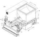
图1为本发明实施例中流质体铺设装置的立体结构示意图;1 is a schematic three-dimensional structure diagram of a fluid body laying device in an embodiment of the present invention;
图2为本发明实施例中流质体铺设装置的局部立体结构示意图;Fig. 2 is the partial three-dimensional structure schematic diagram of the fluid body laying device in the embodiment of the present invention;
图3为本发明实施例中供浆机构的立体结构示意图;3 is a schematic three-dimensional structure diagram of a pulp feeding mechanism in an embodiment of the present invention;
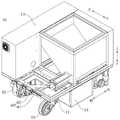
图4为本发明实施例中运动底盘与供浆机构装配的立体结构示意图;FIG. 4 is a schematic three-dimensional structural diagram of the assembly of the moving chassis and the pulp feeding mechanism in the embodiment of the present invention;
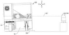
图5为本发明实施例中流质体铺设装置配合激光发生器工作的结构示意图;5 is a schematic structural diagram of a fluid body laying device working with a laser generator in an embodiment of the present invention;
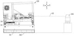
图6为本发明实施例中流质体铺设装置的铺浆机构与施工面保持水平的示意图;FIG. 6 is a schematic diagram of maintaining the level of the slurry-laying mechanism and the construction surface of the fluid body laying device in the embodiment of the present invention;
图7为本发明实施例中流质体铺设装置的铺浆机构向左偏斜的示意图一;7 is a schematic diagram 1 of a leftward deflection of the slurry-laying mechanism of the fluid-body-laying device according to the embodiment of the present invention;
图8为本发明实施例中流质体铺设装置的铺浆机构向左偏斜的示意图二;Fig. 8 is a schematic diagram 2 of the leftward deflection of the slurry-laying mechanism of the fluid-body-laying device according to the embodiment of the present invention;
图9为本发明实施例中流质体铺设装置的铺浆机构向右偏斜的示意图一;Fig. 9 is the schematic diagram 1 of the rightward deflection of the slurry-laying mechanism of the fluid-body-laying device in the embodiment of the present invention;
图10为本发明实施例中流质体铺设装置的铺浆机构向左偏斜的示意图二;Fig. 10 is a schematic diagram 2 of the leftward deflection of the slurry laying mechanism of the fluid body laying device in the embodiment of the present invention;
图11为本发明实施例中流质体铺设装置的铺浆机构不跑偏的示意图;11 is a schematic diagram of the slurry laying mechanism of the fluid body laying device not deviating in the embodiment of the present invention;
图12为本发明实施例中流质体铺设装置的铺浆机构向左跑偏的示意图;Fig. 12 is a schematic diagram of the slurry laying mechanism of the fluid body laying device deviating to the left in the embodiment of the present invention;
图13为本发明实施例中流质体铺设装置的铺浆机构向右跑偏的示意图。Fig. 13 is a schematic diagram of the slurry laying mechanism of the fluid body laying device deviating to the right according to the embodiment of the present invention.
附图标记:Reference number:
100、流质体铺设装置;100. Liquid body laying device;
10、底盘;10. Chassis;
11、底盘主体;12、行走轮;13、电力供给系统;14、控制柜;15、万向轮;11. Chassis body; 12. Walking wheel; 13. Power supply system; 14. Control cabinet; 15. Universal wheel;
20、平移纠偏机构;20. Translation correction mechanism;
21、第一驱动电机;22、丝杠;23、移动座;231、连接板;24、纠偏检测件;25、螺母;26、丝杠支撑座;27、联轴器;28、第一安装座;29、螺母固定座;21, the first drive motor; 22, the lead screw; 23, the movable seat; 231, the connecting plate; 24, the deviation correction detection part; 25, the nut; 29. Nut fixing seat;
30、铺浆机构;30. Pulp spreading mechanism;
31、浆料箱;32、齿形刮板;31. Slurry box; 32. Tooth scraper;
40、供浆机构;40. Pulp supply mechanism;
41、浆料斗;42、螺旋输送杆;43、输送管道;44、第二驱动电机;45、传动链;46、链轮;47、减速机;41, slurry bucket; 42, screw conveying rod; 43, conveying pipeline; 44, second drive motor; 45, transmission chain; 46, sprocket; 47, reducer;
50、上下调平机构;50. Up and down leveling mechanism;
51、升降件;511、第三电机;512、直线电缸;52、旋转件;53、调平检测件;54、直线导轨;55、销轴;56、连接杆;51. Lifting parts; 511, Third motor; 512, Linear electric cylinder; 52, Rotating parts; 53, Leveling detection parts; 54, Linear guide rails; 55, Pin shaft;
60、导向机构;60. Guiding mechanism;
61、滑轨;62、移动滑块;61. Slide rail; 62. Moving slider;
200、激光发生器;300、施工面;O2、水平激光线;O1、垂直激光线。200, laser generator; 300, construction surface; O2, horizontal laser line; O1, vertical laser line.
具体实施方式Detailed ways
下面详细描述本发明的实施例,所述实施例的示例在附图中示出,其中自始至终相同或类似的标号表示相同或类似的元件或具有相同或类似功能的元件。下面通过参考附图描述的实施例是示例性的,仅用于解释本发明,而不能理解为对本发明的限制。The following describes in detail the embodiments of the present invention, examples of which are illustrated in the accompanying drawings, wherein the same or similar reference numerals refer to the same or similar elements or elements having the same or similar functions throughout. The embodiments described below with reference to the accompanying drawings are exemplary, only used to explain the present invention, and should not be construed as a limitation of the present invention.
在本发明的描述中,需要理解的是,术语“中心”、“纵向”、“横向”、“长度”、“宽度”、“上”、“下”、“前”、“后”、“左”、“右”、“竖直”、“水平”、“顶”、“底”、“内”、“外”、“轴向”、“径向”、“周向”等指示的方位或位置关系为基于附图所示的方位或位置关系,仅是为了便于描述本发明和简化描述,而不是指示或暗示所指的装置或元件必须具有特定的方位、以特定的方位构造和操作,因此不能理解为对本发明的限制。此外,限定有“第一”、“第二”的特征可以明示或者隐含地包括一个或者更多个该特征,用于区别描述特征,无顺序之分,无轻重之分。在本发明的描述中,除非另有说明,“多个”的含义是两个或两个以上。In the description of the present invention, it should be understood that the terms "center", "longitudinal", "lateral", "length", "width", "upper", "lower", "front", "rear", " "left", "right", "vertical", "horizontal", "top", "bottom", "inside", "outer", "axial", "radial", "circumferential", etc. Or the positional relationship is based on the orientation or positional relationship shown in the drawings, which is only for the convenience of describing the present invention and simplifying the description, rather than indicating or implying that the referred device or element must have a specific orientation, be constructed and operated in a specific orientation. , so it should not be construed as a limitation of the present invention. In addition, the features defined with "first" and "second" may explicitly or implicitly include one or more of the features, which are used to distinguish and describe the features, regardless of order or importance. In the description of the present invention, unless otherwise specified, "plurality" means two or more.
在本发明的描述中,需要说明的是,除非另有明确的规定和限定,术语“安装”、“相连”、“连接”应做广义理解,例如,可以是固定连接,也可以是可拆卸连接,或一体地连接;可以是机械连接,也可以是电连接;可以是直接相连,也可以通过中间媒介间接相连,可以是两个元件内部的连通。对于本领域的普通技术人员而言,可以具体情况理解上述术语在本发明中的具体含义。In the description of the present invention, it should be noted that the terms "installed", "connected" and "connected" should be understood in a broad sense, unless otherwise expressly specified and limited, for example, it may be a fixed connection or a detachable connection Connection, or integral connection; can be mechanical connection, can also be electrical connection; can be directly connected, can also be indirectly connected through an intermediate medium, can be internal communication between two elements. For those of ordinary skill in the art, the specific meanings of the above terms in the present invention can be understood in specific situations.
下面结合附图,描述本发明实施例的流质体铺设装置100。The fluid
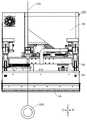
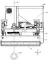
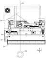
如图1所示,根据本发明实施例的一种流质体铺设装置100,配合激光发生器200使用,包括:底盘10、平移纠偏机构20、铺浆机构30、供浆机构40。As shown in FIG. 1 , a fluid
平移纠偏机构20设在底盘10上,平移纠偏机构20包括沿垂直于流质体铺设方向移动的移动座23和设在移动座23上的纠偏检测件24。铺浆机构30连接在移动座23上。供浆机构40设在底盘10上,以向铺浆机构30供给流质体。可以理解为,铺浆机构30设在底盘10的前端,流质体铺设装置100工作时供浆机构40向铺浆机构30中提供流质体,底盘10带动流质体铺设装置100整体沿直线运动,铺浆机构30对施工面300进行铺浆作业。The
其中,如图5所示,流质体铺设装置100工作时,纠偏检测件24根据接收到的激光线控制所述移动座23,以使铺浆机构30沿铺设方向直线铺浆。也就是说,铺浆机构30正常工作时,纠偏检测件24接收的激光发生器200发出的垂直激光线O1位置为垂直零点位;移动座23用于带动铺浆机构30移动,以使纠偏检测件24接收的垂直激光线O1位置可回到垂直零点位上。例如,用于瓷砖铺设过程中,铺浆机构30在正常工作下沿直线铺浆,由于操作工人的熟练程度因素的影响,底盘10容易偏离铺浆方向,例如,铺浆机构30相对流质体铺设方向向左跑偏或向右跑偏(如图12和图13所示),无法保持沿直线铺浆作业。当纠偏检测件24接收的激光发生器200发出的垂直激光线O1位置不在垂直零点位上时,平移纠偏机构20启动,移动座23带动铺浆机构30沿垂直于底盘10的运动方向移动,从而调整铺浆机构30的位置,使纠偏检测件24接收的垂直激光线O1位置回到垂直零点位上,进而保证铺浆机构30铺设的浆面成直线。As shown in FIG. 5 , when the fluid
根据本发明实施例的流质体铺设铺浆装置100,利用垂直激光线O1作为平行地砖边线基准,纠偏检测件24接受平行地砖边线激光线的信号来控制平移纠偏机构20,对铺浆机构30进行水平方向纠偏,由于现有铺浆机器人因地面平整度、砂砾等杂物的原因,导致机器人行走过程中无法走直线,铺浆无法铺直线,而本发明可保证铺设的浆面沿直线铺设,能替代人工完成粘结流质体的铺设工作,避免因人工作业不规范造成的质量问题,降低工人劳动强度,提高铺浆效率。According to the fluid body laying and
一些实施例中,纠偏检测件24为光电位置敏感传感器。In some embodiments, the
一些实施例中,如图2所示,平移纠偏机构20包括驱动件,驱动件设在移动座23上;运动组件,运动组件包括运动件和连接运动件的导向支撑件,运动件连接驱动件,导向支撑件连接底盘10。In some embodiments, as shown in FIG. 2 , the
具体地,驱动件为第一驱动电机21;运动件为丝杠22,丝杠22连接在第一驱动电机21的输出端上;导向支撑件为螺母25,螺母25配合在丝杠22上,且螺母25连接底盘10。平移纠偏机构20工作时,第一驱动电机21启动带动丝杠22转动,丝杠22对螺母25产生推力,螺母25对丝杠22的反作用力带动移动座23做平移运动,从而带动铺浆机构30水平移动实现平移纠偏。由于纠偏检测件24和铺浆机构30都设在移动座23上,纠偏检测件24通过接受激光发生器200发出的垂直激光线O1可直观反映出铺浆机构30的位置,且纠偏检测件24随铺浆机构30在移动座23上移动,可实时检测出铺浆机构30是否纠偏到位。Specifically, the driving member is the
可选的,如图2所示,丝杠22的另一端可枢转地设有丝杠支撑座26,丝杠支撑座26连接在移动座23上,这样丝杠22和移动座23的连接可靠性增强,丝杠22带动移动座23运动的过程更稳定。丝杠22的一端通过联轴器27连接第一驱动电机21的输出轴,方便丝杠22和第一驱动电机21的安装。Optionally, as shown in FIG. 2 , the other end of the
可选的,丝杠22为滚珠丝杠,当然,本发明中的丝杠22不限于此,这里不再赘述。Optionally, the
可选的,如图2所示,第一驱动电机21为伺服电机,第一驱动电机21连接有第一安装座28,第一安装座28设在移动座23上,以方便安装第一驱动电机21。Optionally, as shown in FIG. 2 , the
可选的,如图2所示,螺母25连接有螺母固定座29,螺母固定座29连接在运动底盘10上,用于方便安装螺母25,提高螺母25与运动底盘10的连接可靠性。Optionally, as shown in FIG. 2 , the
可选的,如图2所示,移动座23上设有连接板231,纠偏检测件24设在连接板231上。Optionally, as shown in FIG. 2 , the moving
一些实施例中,平移纠偏机构20包括齿轮(图未示出)驱动齿条(图未示出)作直线运动的平移机构,例如,第一驱动电机21带动齿轮转动,齿轮啮合齿条带动齿条运动,铺浆机构30连接在齿条上,同样可起到水平移动纠偏的作用。In some embodiments, the
一些实施例中,如图4所示,移动座23与运动底盘10之间设有导向机构60,导向机构60包括滑轨61和移动滑块62,滑轨61设在运动底盘10上且沿运动底盘10的宽度方向设置,移动滑块62配合在滑轨61上且与移动座23相连。移动座23水平移动时,通过滑轨61和移动滑块62的作用,可保证移动座23在运动底盘10上稳定平移,提高运动可靠性。In some embodiments, as shown in FIG. 4 , a
一些实施例中,如图4所示,移动滑块62在滑轨61间隔开地设有多个,例如,移动滑块62为两个。In some embodiments, as shown in FIG. 4 , a plurality of moving
一些实施例中,如图1和图2所示,流质体铺设铺浆装置100还包括上下调平机构50,上下调平机构50设在移动座23和铺浆机构30之间,以调整铺浆机构30的长度方向两端的高度,上下调平机构50包括升降件51和调平检测件53,升降件51设在移动座23上,升降件51的输出端连接铺浆机构30,调平检测件53设在移动座23上。进行上下调平时,升降件51上升使铺浆机构30的端部位置相对施工面300的高度增加,升降件51下降使铺浆机构30的端部位置相对施工面300的高度减小。In some embodiments, as shown in FIG. 1 and FIG. 2 , the fluid body laying and
其中,流质体铺设装置100工作时,调平检测件53根据接收到的激光线控制升降件51升降,以使铺浆机构30的底部与施工面保持平行。也就是说,流质体铺设装置100正常工作时,调平检测件53接收的激光发生器200发出的水平激光线O2位置为水平零点位;上下调平机构50用于带动铺浆机构30升降,以使调平检测件53接收的水平激光线O2位置可回到水平零点位上。瓷砖铺设过程中,铺浆机构30在正常工作下铺浆机构30的底部与施工面300保持水平,由于受到铺设面高低不平的影响,导致铺设的浆面高度不平。当调平检测件53接收的激光发生器200发出的水平激光线O2位置不在水平零点位时,上下调平机构50启动,调整铺浆机构30两端的高度,以使铺浆机构30的底部与施工面300保持平行,进而保证铺浆面高度齐平。利用激光发生器200发出的水平激光线O2作为水平面标高基准,调平检测件53接受水平面标高基准的信号来控制上下调平机构50,以解决因施工面300高低不平而导致铺浆面高低不平的质量问题。Wherein, when the
可选的,调平检测件53为光电位置敏感传感器。Optionally, the leveling
可选的,如图2所示,上下调平机构50为两个,两个上下调平机构50对应设在铺浆机构30的长度方向的两端,以分别调整铺浆机构30的两端的高度。也就是说,两个上下调平机构50可单独调节铺浆机构30两端的高度,例如,如图7和图8所示,当铺浆机构30左端的施工面300较高时,左端的上下调平机构50向上抬升铺浆机构30;当铺浆机构30左端的施工面300较低时,左端的上下调平机构50向下降低调整铺浆机构30。如图9和图10所示,当铺浆机构30右端的施工面300较高时,右端的上下调平机构50向上抬升铺浆机构30;当铺浆机构30右端的施工面300较低时,右端的上下调平机构50向下降低铺浆机构30。Optionally, as shown in FIG. 2 , there are two up-and-down
一些实施例中,如图2所示,升降件51包括第三电机511和直线电缸512,第三电机511与直线电缸512相连以驱动直线电缸512伸缩,直线电缸512的伸缩杆连接在铺浆机构30上。In some embodiments, as shown in FIG. 2 , the lifting
可选的,如图2所示,上下调平机构50还包括旋转件52,旋转件52设在移动座23上且可绕竖直轴线转动,旋转件52的输出端连接调平检测件53,旋转件52可调整调平检测件53的检测方向。旋转件52通过带动调平检测件53转动,使得调平检测件53转动到最佳角度来对准激光发生器200发出的水平激光线O2。Optionally, as shown in FIG. 2 , the up-down
可选的,旋转件52为舵机,舵机的输出端连接调平检测件53,采用舵机方便精准控制调平检测件53的转动角度。当然,旋转件52还可以是步进电机或旋转气缸,这里不再赘述。Optionally, the rotating
一些实施例中,如图2所示,上下调平机构50还包括直线导轨54,直线导轨54与升降件51的输出端相连,直线导轨54的滑块连接移动座23,直线导轨54通过销轴55连接铺浆机构30。也就是说,通过直线导轨54可起到导向作用,升降件51带动铺浆机构30升降时稳定性更好。In some embodiments, as shown in FIG. 2 , the up-down
一些实施例中,如图2所示,直线导轨54的上端通过连接杆56连接升降件51的输出端。In some embodiments, as shown in FIG. 2 , the upper end of the
一些实施例中,如图2所示,铺浆机构30包括:浆料箱31,浆料箱31的下方设有出浆口(图未示出);齿形刮板32,齿形刮板32设在出浆口上,且沿浆料箱31的长度方向延伸。也就是说,浆料箱31内的浆料经出浆口到达齿形刮板32上,并通过齿形刮板32把浆料刮成平直的带齿形的面。In some embodiments, as shown in FIG. 2 , the
可选的,如图3所示,供浆机构40包括:浆料斗41,浆料斗41设在底盘10上;螺旋输送杆42,螺旋输送杆42可枢转地设在浆料斗41内;输送管道43,输送管道43设在浆料斗41上,输送管道43的一端连通螺旋输送杆42的输送端且另一端连通浆料箱31;第二驱动电机44,第二驱动电机44的输出端连接螺旋输送杆42。可以理解为,螺旋输送杆42设置在浆料斗41的底部,第二驱动电机44带动螺旋输送杆42旋转,浆料斗41内的浆料随螺旋输送杆42向输送端排出,接着浆料经输送管道43到达浆料箱31,实现对铺浆机构30的供料。Optionally, as shown in FIG. 3 , the
可选的,如图3所示,第二驱动电机44与螺旋输送杆42之间设有链传动机构,链传动机构包括传动链45和两个链轮46,两个链轮46分别连接第二驱动电机44的输出轴和螺旋输送杆42的轴上,传动链45套设在两个链轮46上。第二驱动电机44启动,带动其上的链轮46转动,经传动链45带动另一链轮46转动,从而驱动螺旋输送杆42旋转。Optionally, as shown in FIG. 3, a chain transmission mechanism is provided between the
可选的,如图3所示,第二驱动电机44为伺服电机,第二驱动电机44和链轮46之间设有减速机47。Optionally, as shown in FIG. 3 , the
一些实施例中,如图4所示,底盘10包括:底盘主体11,供浆机构40设在底盘主体11的上方且位于底盘主体11的宽度方向的一侧;电力供给系统13,电力供给系统13设在底盘主体11的上方且位于底盘主体11的宽度方向的另一侧,电力供给系统13沿底盘主体11的长度方向设置。采用该方式,供浆机构40与电力供给系统13在底盘主体11布局紧凑,有利于缩小整个底盘主体11上部空间的体积。行走轮12,行走轮12设在底盘主体11的下方,电力供给系统13提供行走轮12的电力以带动底盘主体11行走。控制柜14,控制柜14设在底盘主体11的下方,可节省底盘11的上部空间。In some embodiments, as shown in FIG. 4 , the
可选的,如图4所示,行走轮12为舵轮,运动底盘10还包括设在底盘主体11下方的万向轮15。Optionally, as shown in FIG. 4 , the traveling
下面结合附图,描述本发明流质体铺设装置100的一个具体实施例。A specific embodiment of the fluid
如图1至图4所示,一种流质体铺设装置100,配合激光发生器200使用,包括:底盘10、平移纠偏机构20、铺浆机构30、供浆机构40、上下调平机构50。As shown in FIG. 1 to FIG. 4 , a fluid
平移纠偏机构20设在底盘10上,平移纠偏机构20包括沿垂直于流质体铺设方向移动的移动座23和设在移动座23上的纠偏检测件24。The
平移纠偏机构20包括:第一驱动电机21、丝杠22、移动座23、纠偏检测件24、螺母25,第一驱动电机21设在移动座23上;丝杠22的一端连接在第一驱动电机21的输出端上;螺母25配合在丝杠22上,且螺母25连接运动底盘10,纠偏检测件24为光电位置敏感传感器。The
丝杠22的另一端可枢转地设有丝杠支撑座26,丝杠22的一端通过联轴器27连接第一驱动电机21的输出轴,丝杠22为滚珠丝杠,第一驱动电机21为伺服电机,第一驱动电机21连接有第一安装座28,第一安装座28设在移动座23上,螺母25连接有螺母固定座29,螺母固定座29连接在底盘10上,移动座23上设有连接板231,纠偏检测件24设在连接板231上。The other end of the
铺浆机构30连接在移动座23上。铺浆机构30包括:浆料箱31和齿形刮板32,浆料箱31的下方设有出浆口(图未示出);齿形刮板32沿浆料箱31的长度方向设置,且齿形刮板32设在出浆口上。The
供浆机构40设在底盘10上,以向铺浆机构30供给浆料。The
供浆机构40包括:浆料斗41、螺旋输送杆42、输送管道43、第二驱动电机44,浆料斗41设在底盘10上;螺旋输送杆42可枢转地设在浆料斗41内;输送管道43设在浆料斗41上,输送管道43的一端连通螺旋输送杆42的输送端且另一端连通浆料箱31;第二驱动电机44的输出端连接螺旋输送杆42。The
第二驱动电机44与螺旋输送杆42之间设有链传动机构,链传动机构包括传动链45和两个链轮46,两个链轮46分别连接第二驱动电机44的输出轴和螺旋输送杆42的轴上,传动链45套设在两个链轮46上。A chain transmission mechanism is provided between the
第二驱动电机44为伺服电机,第二驱动电机44和链轮46之间设有减速机47。The
上下调平机构50设在移动座23和铺浆机构30之间,上下调平机构50包括调平检测件53,调平检测件53为光电位置敏感传感器,上下调平机构50为两个,两个上下调平机构50对应设在铺浆机构30的长度方向的两端。The up-down
上下调平机构50均包括:升降件51、旋转件52、调平检测件53、直线导轨54。升降件51设在移动座23上,升降件51包括第三电机511和直线电缸512,第三电机511与直线电缸512相连以驱动直线电缸512伸缩,直线电缸512的伸缩杆连接在铺浆机构30上。旋转件52为舵机,舵机的输出端连接调平检测件53。直线导轨54与升降件51的输出端相连,直线导轨54的滑块连接移动座23,直线导轨54通过销轴55连接铺浆机构30。直线导轨54的上端通过连接杆56连接升降件51的输出端。The up-and-down
底盘10包括:底盘主体11、行走轮12、电力供给系统13、控制柜14,供浆机构40设在底盘主体11的上方且位于底盘主体11的宽度方向的一侧;电力供给系统13设在底盘主体11的上方且位于底盘主体11的宽度方向的另一侧,电力供给系统13沿底盘主体11的长度方向设置;行走轮12设在底盘主体11的下方。控制柜14设在底盘主体11的下方,行走轮12为舵轮,运动底盘10还包括设在底盘主体11下方的万向轮15。The
下面描述本发明的工作方法:The working method of the present invention is described below:
如图5所示,把激光发生器200和底盘10放置在图示位置,开启水平激光线O2和垂直激光线O1,供浆机构40的浆料斗41内装满浆料,开启第二驱动电机44驱动减速机47旋转,通过链轮46和传动链45传动,从而带动螺旋输送杆42旋转,螺旋输送杆42输送浆料通过输送管道43输送到浆料箱31,安装在出浆口的齿形刮板32把浆料划出齿型面。As shown in FIG. 5 , place the
底盘10的电力供给系统13提供电力、控制柜14提供控制程序驱动行走轮12带动底盘主体11行走,安装在直线导轨54的上的铺浆机构30也随底盘10运动。The
如图6所示,当地面水平时,底盘10和铺浆机构30的出浆口处于水平状态,铺浆机构30上的调平检测件53接受激光发生器200发出的水平激光线O2位置为水平零点位。As shown in FIG. 6 , when the ground is level, the pulp outlet of the
如图7和图9所示,当地面出现高低不平时,底盘10发生倾斜状态,此时铺浆机构30跟随底盘10发生倾斜,图7底盘10向左偏斜,图9底盘10向右偏斜,铺浆机构30上的调平检测件53感知到激光发生器200发出的水平激光线O2位置离开水平零点位,调平检测件53产生信号,通过程序控制第三电机511驱动直线电缸512的活塞杆做上下运动,从而带动连接杆56、直线导轨54、旋转件52、调平检测件53、销轴55、浆料箱31一起上下运动,直到让激光发生器200发出的水平激光线O2回到调平检测件53的水平零点位,此时出浆口处于水平状态,如图8和图10所示。As shown in FIGS. 7 and 9 , when the ground is uneven, the
如图11所示,当底盘10没有发生偏移时,铺浆机构30的出浆口和底盘10处于对齐状态,此时铺浆机构30上的纠偏检测件24接受激光发生器200发出的垂直激光线O1位置为垂直零点位。如图12和图13所示,当底盘10发生偏移时,此时铺浆机构30随底盘10发生偏移,铺浆机构30上的纠偏检测件24感知到激光发生器200发出的垂直激光线O1位置离开垂直零点位,纠偏检测件24产生信号,通过程序控制第一驱动电机21通过联轴器27驱动丝杠22转动,丝杠22对固定在螺母固定座29上的螺母25产生推力,螺母25对丝杠22产生反作用推力,丝杠22通过丝杠支撑座26让移动座23、连接板231、纠偏检测件24一起做平移运动,直到让激光发生器200发出的垂直激光线O1位置回到纠偏检测件24的垂直零点位。如图12所示,底盘10向右跑偏,平移纠偏机构20的移动座23带动铺浆机构30向左移动纠偏,使接收的垂直激光线O1位置回到垂直零点位;如图13所示,底盘10向左跑偏,平移纠偏机构20的移动座23带动铺浆机构30向右移动纠偏,使接收的垂直激光线O1位置回到垂直零点位。通过该方式,出浆口的位置相对于激光发生器200发出的垂直激光线O1位置保持不变,,可以完成铺贴瓷砖时所需要的在同一水平面的且成直线的带齿型浆面。As shown in FIG. 11 , when the
综上所述,本发明组合底盘10、供浆机构40、平移纠偏机构20、上下调平机构50、铺浆机构30为一体,利用激光发生器200发出激光线作为基准线,能够实现铺设同一水平面的且成直线的带齿型浆面,此外,本发明中的流质体不限于砂浆,还可以是瓷砖胶等。To sum up, the present invention combines the
根据本发明实施例的地砖铺贴机器人(图为示出),包括:根据前文中任一项所述的流质体铺设装置100。A floor tile laying robot (shown in the figure) according to an embodiment of the present invention includes: the liquid
根据本发明实施例的地砖铺贴机器人,通过流质体铺设铺浆装置100,利用垂直激光线O1作为平行地砖边线基准,纠偏检测件24接受平行地砖边线激光线的信号来控制平移纠偏机构20,对铺浆机构30进行水平方向纠偏,可保证铺设的浆面沿直线铺设,能替代人工完成粘结流质体的铺设工作,避免因人工作业不规范造成的质量问题,降低工人劳动强度,提高铺浆效率。According to the floor tile laying robot according to the embodiment of the present invention, through the fluid body laying and
根据本发明实施例的一种铺浆方法,包括:根据前文中的流质体铺设装置100。A slurry laying method according to an embodiment of the present invention includes: according to the foregoing fluid
如图6至图13所示,铺浆方法包括:As shown in Figure 6 to Figure 13, the slurry laying method includes:
步骤S1:运动底盘10沿铺浆方向移动,供浆机构40向铺浆机构30中输送流质体,铺浆机构30对施工面300铺浆。也就是说,流质体铺设装置100正常工作时,施工面300水平,运动底盘10和铺浆机构30处于水平状态,运动底盘10没有发生偏移,铺浆机构30和运动底盘10处于对齐状态,纠偏检测件24接收激光发生器200发出的垂直激光线O1位置为垂直零点位,流质体铺设装置100沿直线铺浆。Step S1 : the moving
步骤S2:纠偏检测件23根据接收到的激光线控制所述平移纠偏机构20,以调整铺浆机构30的水平位置,使流质体保持沿铺设方向直线铺浆。Step S2: The
具体而言,纠偏检测件24接收的垂直激光线O1位置不在垂直零点位时,移动座23带动铺浆机构30移动,直至纠偏检测件24接收的垂直激光线O1位置回到垂直零点位。Specifically, when the position of the vertical laser line O1 received by the deviation
也就是说,当运动底盘10发生偏移时,铺浆机构30和运动底盘10不处于对齐状态,此时纠偏检测件24接收的垂直激光线O1位置不在垂直零点位,平移纠偏机构20启动,移动座23带动铺浆机构30移动纠偏,直至纠偏检测件24接收的垂直激光线O1位置回到垂直零点位为止。That is to say, when the moving
根据本发明实施例的铺浆方法,利用垂直激光线O1作为平行地砖边线基准,纠偏检测件24接受平行地砖边线激光线的信号来控制平移纠偏机构20,对铺浆机构30进行水平方向纠偏。由于现有铺浆机器人因地面平整度、砂砾等杂物的原因,导致机器人行走过程中无法走直线,铺浆无法铺直线,而本发明可保证铺设的浆面沿直线铺设,能替代人工完成粘结流质体的铺设工作,避免因人工作业不规范造成的质量问题,降低工人劳动强度,提高铺浆效率。According to the slurry laying method of the embodiment of the present invention, the vertical laser line O1 is used as the reference of the parallel floor tile edge line, and the
一些实施例中,流质体铺设装置100还包括上下调平机构50,上下调平机构50设在移动座23和铺浆机构30之间,上下调平机构50包括调平检测件53。In some embodiments, the fluid
所述铺浆方法还包括:The slurrying method also includes:
步骤S3:调平检测件53根据激光线控制上下调平机构50,以调整铺浆机构30的高度,使铺浆机构30的底部与施工面保持平行。Step S3: The leveling
具体而言,流质体铺设装置100正常工作时,调平检测件53接收激光发生器200发出的水平激光线O2位置为水平零点位。流质体铺设装置100作业时,调平检测件53接收的水平激光线O2位置不在水平零点位时,上下调平机构50带动铺浆机构30的至少一端升降,直至调平检测件53接收的水平激光线O2位置回到水平零点位。Specifically, when the
也就是说,当施工面300不水平时,运动底盘10和铺浆机构30不处于水平状态,此时调平检测件53接收的水平激光线O2位置不在水平零点位,上下调平机构50启动,带动铺浆机构30的左端或右端升降,直至调平检测件53接收的水平激光线O2位置回到水平零点位为止。That is to say, when the
根据本发明实施例的流质体铺设装置100的其他构成等以及操作对于本领域普通技术人员而言都是已知的,这里不再详细描述。Other structures, etc. and operations of the fluid
在本说明书的描述中,参考术语“实施例”、“示例”等的描述意指结合该实施例或示例描述的具体特征、结构、材料或者特点包含于本发明的至少一个实施例或示例中。在本说明书中,对上述术语的示意性表述不一定指的是相同的实施例或示例。而且,描述的具体特征、结构、材料或者特点可以在任何的一个或多个实施例或示例中以合适的方式结合。In the description of this specification, description with reference to the terms "embodiment," "example," etc. means that a particular feature, structure, material, or characteristic described in connection with the embodiment or example is included in at least one embodiment or example of the present invention . In this specification, schematic representations of the above terms do not necessarily refer to the same embodiment or example. Furthermore, the particular features, structures, materials or characteristics described may be combined in any suitable manner in any one or more embodiments or examples.
尽管已经示出和描述了本发明的实施例,本领域的普通技术人员可以理解:在不脱离本发明的原理和宗旨的情况下可以对这些实施例进行多种变化、修改、替换和变型,本发明的范围由权利要求及其等同物限定。Although embodiments of the present invention have been shown and described, it will be understood by those of ordinary skill in the art that various changes, modifications, substitutions and alterations can be made in these embodiments without departing from the principles and spirit of the invention, The scope of the invention is defined by the claims and their equivalents.
Claims (10)
Translated fromChinesePriority Applications (3)
| Application Number | Priority Date | Filing Date | Title |
|---|---|---|---|
| CN202010619799.8ACN113882635B (en) | 2020-07-01 | 2020-07-01 | Fluidized body laying device, floor tile laying robot and slurry laying method |
| PCT/CN2021/098880WO2022001597A1 (en) | 2020-07-01 | 2021-06-08 | Fluid laying device, floor tile laying robot and slurry laying method |
| US18/004,061US20230265666A1 (en) | 2020-07-01 | 2021-06-08 | Fluid Laying Device, Floor Tile Laying Robot and Slurry Laying Method |
Applications Claiming Priority (1)
| Application Number | Priority Date | Filing Date | Title |
|---|---|---|---|
| CN202010619799.8ACN113882635B (en) | 2020-07-01 | 2020-07-01 | Fluidized body laying device, floor tile laying robot and slurry laying method |
Publications (2)
| Publication Number | Publication Date |
|---|---|
| CN113882635A CN113882635A (en) | 2022-01-04 |
| CN113882635Btrue CN113882635B (en) | 2022-09-16 |
Family
ID=79012518
Family Applications (1)
| Application Number | Title | Priority Date | Filing Date |
|---|---|---|---|
| CN202010619799.8AActiveCN113882635B (en) | 2020-07-01 | 2020-07-01 | Fluidized body laying device, floor tile laying robot and slurry laying method |
Country Status (3)
| Country | Link |
|---|---|
| US (1) | US20230265666A1 (en) |
| CN (1) | CN113882635B (en) |
| WO (1) | WO2022001597A1 (en) |
Families Citing this family (1)
| Publication number | Priority date | Publication date | Assignee | Title |
|---|---|---|---|---|
| CN114161432A (en)* | 2020-09-10 | 2022-03-11 | 广东博智林机器人有限公司 | Fluid body material transporting robot |
Family Cites Families (12)
| Publication number | Priority date | Publication date | Assignee | Title |
|---|---|---|---|---|
| JP2814345B2 (en)* | 1994-02-17 | 1998-10-22 | 五洋建設株式会社 | Concrete leveling device |
| US7293938B1 (en)* | 2005-06-30 | 2007-11-13 | Suckow Robert E | Breakdown screed plate |
| CN103194954A (en)* | 2012-01-06 | 2013-07-10 | 蔡墩军 | Laser material distributing, lying and leveling machine |
| AT514294B1 (en)* | 2013-05-14 | 2015-08-15 | Egon Döberl | Device for leveling piles and building materials |
| CN205025113U (en)* | 2015-07-29 | 2016-02-10 | 江苏科瑞欣机械有限公司 | Laser flattening machine people that paves |
| CN205840353U (en)* | 2016-07-11 | 2016-12-28 | 施世清 | A kind of intelligent ground evener |
| CN108252500B (en)* | 2018-01-22 | 2021-05-18 | 广东非凡实业投资有限公司 | Multifunctional full-automatic floor tile paving machine |
| CN109930801A (en)* | 2019-04-30 | 2019-06-25 | 广东博智林机器人有限公司 | Paving slurry equipment |
| CN210508451U (en)* | 2019-06-21 | 2020-05-12 | 中国建筑第二工程局有限公司 | Uniform material spreading device for building |
| CN110453901A (en)* | 2019-08-19 | 2019-11-15 | 广东博智林机器人有限公司 | Material installation apparatus and its control method |
| CN110439238A (en)* | 2019-08-19 | 2019-11-12 | 广东博智林机器人有限公司 | Material laying machine people with leveling structure |
| CN110593573B (en)* | 2019-08-26 | 2021-09-07 | 广东博智林机器人有限公司 | Correction device and correction method of floating robot and floating robot |
- 2020
- 2020-07-01CNCN202010619799.8Apatent/CN113882635B/enactiveActive
- 2021
- 2021-06-08USUS18/004,061patent/US20230265666A1/ennot_activeAbandoned
- 2021-06-08WOPCT/CN2021/098880patent/WO2022001597A1/ennot_activeCeased
Also Published As
| Publication number | Publication date |
|---|---|
| WO2022001597A1 (en) | 2022-01-06 |
| US20230265666A1 (en) | 2023-08-24 |
| CN113882635A (en) | 2022-01-04 |
Similar Documents
| Publication | Publication Date | Title |
|---|---|---|
| WO2022262505A1 (en) | Sheet paving device, paving method, plate coating apparatus, and sheet paving apparatus | |
| CN101597953B (en) | Automatic leveling plastering machine | |
| CN201620587U (en) | Self-leveling troweling machine | |
| CN204524643U (en) | To pipe device | |
| CN107553687B (en) | 3D house printer | |
| CN111350354B (en) | Multifunctional scraper blade assembly and leveling trowelling machine | |
| CN110295732B (en) | A fully automatic floor tile laying equipment | |
| RU2589776C2 (en) | Concrete finishing machine for levelling floor bases | |
| CN113882635B (en) | Fluidized body laying device, floor tile laying robot and slurry laying method | |
| CN103182733B (en) | Trowelling machine | |
| CN111550023A (en) | Construction method for mounting and fixing building prefabricated part | |
| CN107756599B (en) | Working method of the automatic water collection and smoothing system for the arc surface of the cement segment | |
| CN111910642B (en) | A ditch concrete slipform paver | |
| US5190396A (en) | Concrete leveling apparatus | |
| CN119501410A (en) | Pipe pile welding device | |
| CN115701471A (en) | An intelligent plastering robot and plastering method | |
| HK40065951A (en) | Fluid laying device, floor tile paving robot, and slurry laying method | |
| HK40065951B (en) | Fluid laying device, floor tile paving robot, and slurry laying method | |
| CN115478667B (en) | Sheet material paving equipment and paving method | |
| CN110836020A (en) | Movable wall-building mortar paving method | |
| CN110878639B (en) | A mobile masonry wall grouting positioning method | |
| CN115627679A (en) | Laser leveling equipment and method for non-indentation ground construction | |
| CN204897233U (en) | Canopy is driven with automatic rising to loader | |
| CN113863952B (en) | Anchor lining shotcrete machine | |
| CN117188264A (en) | Automatic brick paving machine |
Legal Events
| Date | Code | Title | Description |
|---|---|---|---|
| PB01 | Publication | ||
| PB01 | Publication | ||
| SE01 | Entry into force of request for substantive examination | ||
| SE01 | Entry into force of request for substantive examination | ||
| REG | Reference to a national code | Ref country code:HK Ref legal event code:DE Ref document number:40065951 Country of ref document:HK | |
| GR01 | Patent grant | ||
| GR01 | Patent grant | ||
| TR01 | Transfer of patent right | Effective date of registration:20240403 Address after:528225, Room 204-2, 2nd Floor, Office Building, Zone A, No. 40 Boai Middle Road, Shishan Town, Nanhai District, Foshan City, Guangdong Province (Residence Declaration) Patentee after:Pai Turner (Foshan) Robot Technology Co.,Ltd. Country or region after:China Address before:201-11, second floor, East office, No. 11, Junye East Road, Beijiao Industrial Park, Shunjiang neighborhood committee, Beijiao Town, Shunde District, Foshan City, Guangdong Province Patentee before:GUANGDONG BOZHILIN ROBOT Co.,Ltd. Country or region before:China | |
| TR01 | Transfer of patent right | ||
| CP03 | Change of name, title or address | Address after:Room 302, Building 1, No. 11 Daxue Road, Songshan Lake Park, Dongguan City, Guangdong Province 523808 Patentee after:Paitna (Dongguan) Robot Technology Co.,Ltd. Country or region after:China Address before:Room 204-2, 2nd Floor, Office Building A, No. 40-1 Bo'ai Middle Road, Shishan Town, Nanhai District, Foshan City, Guangdong Province (Address Declaration) Patentee before:Pai Turner (Foshan) Robot Technology Co.,Ltd. Country or region before:China | |
| CP03 | Change of name, title or address |