CN113878583B - Underwater mechanical arm control method and system - Google Patents
Underwater mechanical arm control method and systemDownload PDFInfo
- Publication number
- CN113878583B CN113878583BCN202111279583.2ACN202111279583ACN113878583BCN 113878583 BCN113878583 BCN 113878583BCN 202111279583 ACN202111279583 ACN 202111279583ACN 113878583 BCN113878583 BCN 113878583B
- Authority
- CN
- China
- Prior art keywords
- underwater
- manipulator
- module
- underwater manipulator
- kinematics model
- Prior art date
- Legal status (The legal status is an assumption and is not a legal conclusion. Google has not performed a legal analysis and makes no representation as to the accuracy of the status listed.)
- Active
Links
- 238000000034methodMethods0.000titleclaimsabstractdescription28
- XLYOFNOQVPJJNP-UHFFFAOYSA-NwaterSubstancesOXLYOFNOQVPJJNP-UHFFFAOYSA-N0.000claimsabstractdescription30
- 230000003068static effectEffects0.000claimsdescription19
- 230000005484gravityEffects0.000claimsdescription10
- 230000001133accelerationEffects0.000claimsdescription2
- 239000000463materialSubstances0.000claimsdescription2
- 230000009471actionEffects0.000abstractdescription3
- 238000010586diagramMethods0.000description7
- 239000011159matrix materialSubstances0.000description5
- 230000009466transformationEffects0.000description5
- 230000036544postureEffects0.000description3
- 230000008569processEffects0.000description3
- 238000012986modificationMethods0.000description2
- 230000004048modificationEffects0.000description2
- 230000004044responseEffects0.000description2
- 238000013459approachMethods0.000description1
- 230000008901benefitEffects0.000description1
- 238000012937correctionMethods0.000description1
- 239000012636effectorSubstances0.000description1
- 239000012530fluidSubstances0.000description1
- 238000005259measurementMethods0.000description1
- 238000005457optimizationMethods0.000description1
- 230000008092positive effectEffects0.000description1
- 238000012545processingMethods0.000description1
- 238000004088simulationMethods0.000description1
- 238000003756stirringMethods0.000description1
Images


Classifications
- B—PERFORMING OPERATIONS; TRANSPORTING
- B25—HAND TOOLS; PORTABLE POWER-DRIVEN TOOLS; MANIPULATORS
- B25J—MANIPULATORS; CHAMBERS PROVIDED WITH MANIPULATION DEVICES
- B25J9/00—Programme-controlled manipulators
- B25J9/16—Programme controls
- B25J9/1602—Programme controls characterised by the control system, structure, architecture
- B—PERFORMING OPERATIONS; TRANSPORTING
- B25—HAND TOOLS; PORTABLE POWER-DRIVEN TOOLS; MANIPULATORS
- B25J—MANIPULATORS; CHAMBERS PROVIDED WITH MANIPULATION DEVICES
- B25J18/00—Arms
- B—PERFORMING OPERATIONS; TRANSPORTING
- B25—HAND TOOLS; PORTABLE POWER-DRIVEN TOOLS; MANIPULATORS
- B25J—MANIPULATORS; CHAMBERS PROVIDED WITH MANIPULATION DEVICES
- B25J9/00—Programme-controlled manipulators
- B25J9/16—Programme controls
- B25J9/1656—Programme controls characterised by programming, planning systems for manipulators
- B25J9/1664—Programme controls characterised by programming, planning systems for manipulators characterised by motion, path, trajectory planning
Landscapes
- Engineering & Computer Science (AREA)
- Robotics (AREA)
- Mechanical Engineering (AREA)
- Automation & Control Theory (AREA)
- Manipulator (AREA)
Abstract
Description
Translated fromChinese技术领域technical field
本发明公开了一种水下机械臂控制方法及系统。The invention discloses an underwater mechanical arm control method and system.
背景技术Background technique
水下机械臂的运动学问题主要研究的是机械臂末端执行器与机械臂关节变量之间的位置和方向关系,包括正运动学和逆运动学两个基本问题。机械臂正运动学方程可以用于机械臂的正向控制,而逆运动学是机械臂轨迹规划和运动控制的基础。所以说建立正确、准确的机械臂运动学模型对于机械臂的精准位置控制具有重要意义。The kinematics of the underwater manipulator mainly studies the position and direction relationship between the end effector of the manipulator and the joint variables of the manipulator, including two basic problems of forward kinematics and inverse kinematics. The forward kinematics equation of the manipulator can be used for the forward control of the manipulator, while the inverse kinematics is the basis of the trajectory planning and motion control of the manipulator. Therefore, it is of great significance to establish a correct and accurate kinematics model of the manipulator for the precise position control of the manipulator.
水下机械臂在靠近定点作业目标的过程中,存在着模型不确定性及水流干扰的情况。目前水下机械臂的位置控制方法主要是使用关节控制的方法对水下机械臂的关节角度进行控制,而关节角度需要通过运动学模型计算所得。When the underwater manipulator approaches the fixed-point operation target, there are model uncertainties and water flow interference. At present, the position control method of the underwater manipulator mainly uses the joint control method to control the joint angle of the underwater manipulator, and the joint angle needs to be calculated through the kinematics model.
但是,目前的水下机械臂运动学模型的建立过程中都没有考虑机械臂结构受水流作用而产生的形变,这种形变在机械臂结构刚性较小,工作环境水流大的情况下更为明显,形变的出现势必会导致机械臂末端的位置出现偏移,位置偏移的存在会导致机械臂的位置精度的降低,这对于一些精度要求较高的场所影响较大,目前解决这种误差的主要方法是通过水下机械臂末端传感器的位置测量与控制算法相结合进行后置反馈调节,这一方法过于繁琐且响应迟缓。However, the current kinematic model of the underwater manipulator does not consider the deformation of the manipulator structure due to the action of the water flow. This deformation is more obvious when the manipulator structure is less rigid and the water flow is large in the working environment. , the occurrence of deformation will inevitably lead to a shift in the position of the end of the manipulator, and the existence of the position shift will lead to a decrease in the positional accuracy of the manipulator, which will have a greater impact on some places with high precision requirements. The main method is to perform post-feedback adjustment by combining the position measurement of the sensor at the end of the underwater manipulator with the control algorithm. This method is too cumbersome and slow in response.
发明内容Contents of the invention
本发明是针对目前现有水下机械臂存在受水流作用力而产生的末端位置偏移的问题而提出的一种水下机械臂控制方法及系统,该方法和系统在建立机械臂运动学模型的过程中考虑到机械臂受水流作用而产生的形变,所建立的运动学模型的准确度大大提高,对后续的轨迹规划、精准的位置控制具有重要意义。The present invention proposes a control method and system for an underwater manipulator aiming at the problem that the current existing underwater manipulator has end position offset caused by the force of the water flow. In the process of taking into account the deformation of the mechanical arm caused by the action of water flow, the accuracy of the established kinematics model is greatly improved, which is of great significance for the subsequent trajectory planning and precise position control.
本发明采用的技术方案如下:The technical scheme that the present invention adopts is as follows:
第一方面,本发明提出了一种水下机械臂控制方法,包括如下步骤:In a first aspect, the present invention proposes a method for controlling an underwater robotic arm, comprising the steps of:
步骤一:运用D-H法建立水下机械臂的运动学模型;Step 1: Use the D-H method to establish the kinematics model of the underwater manipulator;
步骤二:对水下机械臂的受力状况进行分析,得到各个力的值;Step 2: Analyze the force condition of the underwater manipulator to obtain the value of each force;
步骤三:运用ANSYS对机械臂结构进行静力学分析,得到不同角度下水下机械臂末端的变形量;Step 3: Use ANSYS to conduct static analysis on the structure of the robotic arm to obtain the deformation of the end of the underwater robotic arm at different angles;
步骤四:将所得的水下机械臂末端变形量数据进行曲线拟合,得到有关于关节角度与水下机械臂末端偏移量的函数方程;Step 4: Carry out curve fitting on the obtained deformation data of the end of the underwater manipulator, and obtain a functional equation about the joint angle and the offset of the end of the underwater manipulator;
步骤五:将上一步所得到的末端位置偏移函数方程加入到水下机械臂运动学模型中,达到修正水下机械臂运动学模型的目的;Step 5: Add the terminal position offset function equation obtained in the previous step to the kinematics model of the underwater manipulator to achieve the purpose of correcting the kinematics model of the underwater manipulator;
步骤六:通过修正后的正运动学模型进行轨迹规划,根据曲线特点以及实际工作要求选取N个末端位置坐标Pi(xi,yi,zi)。Step 6: Perform trajectory planning through the corrected forward kinematics model, and select N end position coordinates Pi (xi , yi , zi) according to the characteristics of the curve and actual work requirements.
步骤七:将获取的N个点通过修正后的逆运动学模型进行运动学反解的计算。得到每一个轨迹坐标点对应的驱动关节所对应的角度值θij。Step 7: Calculating the inverse kinematics solution of the obtained N points through the revised inverse kinematics model. Obtain the angle value θij corresponding to the driving joint corresponding to each trajectory coordinate point.
步骤八:将上述得到的转动角度下发至运动控制器,通过伺服驱动系统驱动各关机器转动相应角度,各连杆联动完后预定的运动轨迹,从而达到目标位置。Step 8: Send the rotation angle obtained above to the motion controller, drive each machine to rotate by the corresponding angle through the servo drive system, and reach the target position according to the predetermined movement trajectory after the linkage of each connecting rod.
另一方面,本发明还提出了一种水下机械臂控制系统,包括On the other hand, the present invention also proposes an underwater manipulator control system, comprising
第一模块,被配置为建立水下机械臂的运动学模型;The first module is configured to establish a kinematics model of the underwater robotic arm;
第二模块,被配置为对水下机械臂的受力状况进行分析,得到各个力的值;The second module is configured to analyze the force condition of the underwater mechanical arm to obtain the value of each force;
第三模块,被配置为对机械臂结构进行静力学分析,得到不同角度下水下机械臂末端的变形量;The third module is configured to perform static analysis on the structure of the manipulator to obtain the deformation of the end of the underwater manipulator at different angles;
第四模块,被配置为将所得的水下机械臂末端变形量数据进行曲线拟合,得到有关于关节角度与水下机械臂末端偏移量的函数方程;The fourth module is configured to perform curve fitting on the obtained deformation data of the end of the underwater manipulator to obtain a functional equation about the joint angle and the offset of the end of the underwater manipulator;
第五模块,被配置为将得到的末端位置偏移函数方程加入到水下机械臂运动学模型中,达到修正水下机械臂运动学模型的目的;The fifth module is configured to add the obtained terminal position offset function equation into the kinematics model of the underwater manipulator, so as to achieve the purpose of correcting the kinematics model of the underwater manipulator;
第六模块,被配置为通过修正后的正运动学模型进行轨迹规划,根据曲线特点以及实际工作要求选取N个末端位置坐标Pi(xi,yi,zi);The sixth module is configured to perform trajectory planning through the corrected forward kinematics model, and select N end position coordinates Pi (xi , yi , zi ) according to the characteristics of the curve and actual work requirements;
第七模块:被配置为将获取的N个点通过修正后的逆运动学模型进行运动学反解的计算;得到每一个轨迹坐标点对应的驱动关节所对应的角度值θij;The seventh module: configured to calculate the inverse kinematics solution of the acquired N points through the modified inverse kinematics model; obtain the angle value θij corresponding to the driving joint corresponding to each trajectory coordinate point;
第八模块:被配置为将得到的角度值θij发送至运动控制器,通过伺服驱动系统驱动各关机器转动相应角度,各连杆联动完后预定的运动轨迹,从而达到目标位置。The eighth module: it is configured to send the obtained angle value θij to the motion controller, and drive each closing machine to rotate the corresponding angle through the servo drive system, and the predetermined movement trajectory after the linkage of each connecting rod is completed, so as to reach the target position.
本发明具有以下的优点与积极效果:The present invention has following advantage and positive effect:
本发明所提出的通过修正水下机械臂运动学模型,从而达到主动,快速,精准的位置控制的方法,能够在控制时更快的响应以及精准位置控制,减少了后期位置反馈调节的时间,提高了水下机械臂末端位置精度,使水下机械臂能够更快,更准确的到达指定位置。The method proposed by the present invention achieves active, fast, and precise position control by correcting the kinematics model of the underwater manipulator, which can provide faster response and precise position control during control, reducing the time for post-position feedback adjustment. The position accuracy of the end of the underwater robotic arm is improved, so that the underwater robotic arm can reach the designated position faster and more accurately.
附图说明Description of drawings
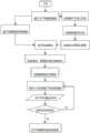
图1:控制方法流程图;Figure 1: Flowchart of the control method;
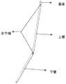
图2:二连杆平面水下机械臂三维模型图;Figure 2: Three-dimensional model of the two-link planar underwater manipulator;
图3:机械臂参考坐标系;Figure 3: The reference coordinate system of the manipulator;
图4:水下机械臂受力分析图;Figure 4: Force analysis diagram of underwater manipulator;
图5:静力学分析流程图;Figure 5: Static analysis flow chart;
图6:水下机械臂末端X向变形散点图;Figure 6: The X-direction deformation scatter diagram of the end of the underwater manipulator;
图7:水下机械臂末端Y向变形散点图;Figure 7: Scatter diagram of Y-direction deformation at the end of the underwater manipulator;
图8:水下机械臂末端X向变形拟合曲线图;Figure 8: The X-direction deformation fitting curve at the end of the underwater manipulator;
图9:水下机械臂末端Y向变形拟合曲线图;Figure 9: The Y-direction deformation fitting curve at the end of the underwater manipulator;
图10:反函数拟合曲线图。Figure 10: Inverse Function Fitting Curve.
具体实施方式Detailed ways
应该指出,以下详细说明都是例示性的,旨在对本申请提供进一步的说明。除非另有指明,本实施例使用的所有技术和科学术语具有与本申请所属技术领域的普通技术人员通常理解的相同含义。It should be pointed out that the following detailed description is exemplary and intended to provide further explanation to the present application. Unless otherwise specified, all technical and scientific terms used in this embodiment have the same meaning as commonly understood by one of ordinary skill in the art to which this application belongs.
需要注意的是,这里所使用的术语仅是为了描述具体实施方式,而非意图限制根据本申请的示例性实施方式。如在这里所使用的,除非上下文另外明确指出,否则单数形式也意图包括复数形式,此外,还应当理解的是,当在本说明书中使用术语“包含”和/或“包括”时,其指明存在特征、步骤、操作、器件、组件和/或它们的组合。It should be noted that the terminology used here is only for describing specific implementations, and is not intended to limit the exemplary implementations according to the present application. As used herein, unless the context clearly dictates otherwise, the singular is intended to include the plural, and it should also be understood that when the terms "comprising" and/or "comprising" are used in this specification, they mean There are features, steps, operations, means, components and/or combinations thereof.
为了解决现有技术中存在的技术问题,本实施例公开了一种水下机械臂控制方法,包括如下步骤:In order to solve the technical problems existing in the prior art, this embodiment discloses a method for controlling an underwater manipulator, including the following steps:
步骤1:运用D-H法建立水下机械臂的运动学模型;Step 1: Establish the kinematics model of the underwater manipulator using the D-H method;
步骤2:对水下机械臂的受力状况进行分析,得到各个力的值;Step 2: Analyze the force condition of the underwater robotic arm to obtain the value of each force;
步骤3:运用ANSYS对机械臂结构进行静力学分析,得到不同角度下水下机械臂末端的变形量;Step 3: Use ANSYS to conduct static analysis on the structure of the robotic arm to obtain the deformation of the end of the underwater robotic arm at different angles;
步骤4:将所得的水下机械臂末端变形量数据进行曲线拟合,得到有关于关节角度与水下机械臂末端偏移量的函数方程;Step 4: Carry out curve fitting on the obtained deformation data of the end of the underwater manipulator, and obtain a functional equation about the joint angle and the offset of the end of the underwater manipulator;
步骤5:将上一步所得到的末端位置偏移函数方程加入到水下机械臂运动学模型中,达到修正水下机械臂运动学模型的目的;Step 5: Add the terminal position offset function equation obtained in the previous step to the kinematics model of the underwater manipulator to achieve the purpose of correcting the kinematics model of the underwater manipulator;
步骤6:通过修正后的正运动学模型进行轨迹规划,根据曲线特点以及实际工作要求选取N个末端位置坐标Pi(xi,yi,zi)。Step 6: Perform trajectory planning through the corrected forward kinematics model, and select N end position coordinates Pi (xi , yi , zi) according to the characteristics of the curve and actual work requirements.
步骤7:将获取的N个点通过修正后的逆运动学模型进行运动学反解的计算。得到每一个轨迹坐标点对应的驱动关节所对应的角度值θij。Step 7: Calculate the inverse kinematics solution of the acquired N points through the corrected inverse kinematics model. Obtain the angle value θij corresponding to the driving joint corresponding to each trajectory coordinate point.
步骤8:将上述得到的转动角度下发至运动控制器,通过伺服驱动系统驱动各关机器转动相应角度,各连杆联动完后预定的运动轨迹,从而达到目标位置。Step 8: Send the rotation angle obtained above to the motion controller, drive each machine to rotate by the corresponding angle through the servo drive system, and reach the target position according to the predetermined movement trajectory after the linkage of each connecting rod.
本发明以平面二连杆水下机械臂为对象,对所提出的步骤一至步骤五进行了解释说明。The present invention takes the planar two-link underwater mechanical arm as an object, and explains the proposed
步骤1:水下机械臂运动学模型建立Step 1: Establishment of the kinematics model of the underwater manipulator
1.1正运动学模型的建立1.1 Establishment of forward kinematics model
水下机械臂正运动学方程可以用于机械臂的正向控制,其对于轨迹规划与末端位置求解具有重要作用。The forward kinematic equation of the underwater manipulator can be used for the forward control of the manipulator, which plays an important role in trajectory planning and terminal position solution.
如附图2为二连杆水下机械臂模型图,由图可见,所建立的模型主要包括四部分,分别是基座、上臂、下臂以及关节销,每个关节均为旋转关节;对各个关节进行分析,根据D-H法则,建立如附图3所示的参考坐标系;将水下机械臂的D-H参数代入连杆齐次变换矩阵的一般表达式,可得到相邻连杆间的坐标变换矩阵:As shown in Figure 2, it is a model diagram of a two-link underwater manipulator. It can be seen from the figure that the established model mainly includes four parts, namely the base, the upper arm, the lower arm and the joint pin, and each joint is a rotary joint; Each joint is analyzed, and according to the D-H rule, the reference coordinate system shown in Figure 3 is established; the D-H parameters of the underwater manipulator are substituted into the general expression of the homogeneous transformation matrix of the connecting rod, and the coordinates between adjacent connecting rods can be obtained Transformation matrix:

由下式可计算出该机械臂的运动学方程,这样得到的末端坐标系到基坐标系的变换矩阵为The kinematic equation of the manipulator can be calculated from the following formula, so that the transformation matrix from the end coordinate system to the base coordinate system is

由于机械臂末端坐标是在坐标系{2}内,是在坐标系{2}的基础上平移a2,不存在旋转变换,所以末端坐标到末端坐标系{2}的变换矩阵为:Since the end coordinates of the manipulator are in the coordinate system {2}, they are translated by a2 on the basis of the coordinate system {2}, and there is no rotation transformation, so the transformation matrix from the end coordinates to the end coordinate system {2} is:

那么可以由得到末端坐标相对于基座标系的位姿矩阵,也是此平面二连杆机械臂模型的运动学方程:Then the pose matrix of the end coordinates relative to the base coordinate system can be obtained, which is also the kinematic equation of the planar two-link manipulator model:

1.2逆运动学模型建立1.2 Inverse kinematics model establishment
逆运动学模型的建立对于水下机械臂的位置控制至关重要。对于附图2所示的水下机械臂,在已知末端坐标为(x3,y3)的情况下,结合正运动学方程可以得到以下两个个非线性方程,进而可以求出θ1,θ2。The establishment of the inverse kinematics model is very important for the position control of the underwater manipulator. For the underwater manipulator shown in Figure 2, when the terminal coordinates are known as (x3 , y3 ), combined with the forward kinematics equation, the following two nonlinear equations can be obtained, and then θ1 can be obtained , θ2 .
x3=a1 cosθ1+a2 cos(θ1+θ2)x3 =a1 cosθ1 +a2 cos(θ1 +θ2 )
y3=a1 sinθ1+a2 sin(θ1+θ2)y3 =a1 sinθ1 +a2 sin(θ1 +θ2 )
将上面两个式子平方相加可以得到下式,Adding the squares of the above two equations gives the following equation,

由上式求解cosθ2,得到下式,Solve the cosθ2 from the above formula to get the following formula,

应用双变量反正切公式计算θ1,得到下式,Apply the bivariate arctangent formula to calculate θ1 , and get the following formula,
θ2=Atan2(sinθ2,cosθ2)θ2 =Atan2(sinθ2 , cosθ2 )
最后,由下式便可以求得θ1的值,Finally, the value ofθ1 can be obtained from the following formula,

步骤2:水下机械臂受力分析Step 2: Force analysis of underwater manipulator
机械臂在水中工作时,其受到的力可以视为由两部分组成。第一部分是在静水环境下,因机械臂的主动运动搅动水导致的受力;第二部分是在水环境下,当机械臂以某个位姿静止不动时,仅受水流冲击的受力。在解释中,我们只分析机械臂在水流速度恒定的环境下,机械臂运动到不同位姿静止不动时的变形情况,所以此时的机械臂只受恒定水流冲击的力。When the mechanical arm works in water, the force it receives can be regarded as composed of two parts. The first part is the force caused by the active movement of the robotic arm stirring the water in a still water environment; the second part is the force that is only impacted by the water flow when the robotic arm is stationary in a certain posture in a water environment . In the explanation, we only analyze the deformation of the manipulator when the water velocity is constant, and the manipulator moves to different poses and stands still, so the manipulator at this time is only subjected to the force of constant water flow impact.
水下机械臂手受水流冲击作用时,流体会对水下机械臂表面产生一定的阻力,水下机械臂的连杆按照阻力的方向可以分解为法向阻力与切向阻力,因为机械臂的连杆是圆柱体,所以其切向阻力通常忽略不计。本发明中基于微元法和Morison公式对水下机械臂的单个连杆进行了受力分析,如附图4所示。When the underwater manipulator hand is impacted by the water flow, the fluid will produce a certain resistance on the surface of the underwater manipulator. The connecting rod of the underwater manipulator can be decomposed into normal resistance and tangential resistance according to the direction of resistance, because the manipulator Connecting rods are cylindrical, so their tangential resistance is usually negligible. In the present invention, based on the microelement method and the Morison formula, the force analysis of the single connecting rod of the underwater manipulator is carried out, as shown in Figure 4.
综合以上分析,在恒流环境下,处于静止状态的水下机械臂主要受水阻力,重力,浮力,阻力可以通过下式计算得到,Based on the above analysis, in a constant flow environment, the underwater manipulator in a static state is mainly affected by water resistance, gravity, buoyancy, and resistance can be calculated by the following formula,

式中,Fdi—连杆所受的水阻力,上杆为Fd1,下杆Fd2;ρ—水的密度;CD—水阻系数,本实施例取CD=1.2;v—水流速度;Ai—连杆在垂直于来流速度v方向的投影面积,上连杆为A1=a1Dcosθ1,下杆为A1=a2Dcos(θ1+θ2),此处D为连杆的等效直径。In the formula, Fdi —the water resistance of the connecting rod, the upper rod is Fd1 , and the lower rod is Fd2 ; ρ—the density of water; CD —the water resistance coefficient, which is taken as CD =1.2 in this embodiment; v—water flow Velocity; Ai —the projected area of the connecting rod in the direction perpendicular to the incoming flow velocity v, the upper connecting rod is A1 =a1 Dcosθ1 , the lower rod is A1 =a2 Dcos(θ1 +θ2 ), where D is the equivalent diameter of the connecting rod.
由于重力与浮力的方向是相反的,所以在假设连杆重心和浮心重合的情况下用一个向下的等效重力来代替重力和浮力,即:Since the directions of gravity and buoyancy are opposite, a downward equivalent gravity is used to replace gravity and buoyancy under the assumption that the center of gravity of the connecting rod coincides with the center of buoyancy, namely:

其中,m—上下连杆的总质量;g—重力加速度;V—连杆的体积;ρ—水的密度;;ρm—连杆材料的密度。Among them, m—the total mass of the upper and lower connecting rods; g—the acceleration of gravity; V—the volume of the connecting rod; ρ—the density of water; ρm —the density of the connecting rod material.
步骤3:静力学分析Step 3: Static Analysis
静力学分析一般应用于分析结构在承担恒定不变的载荷条件下的变形和应力情况。本部分要进行的是在ANSYS Workbench中利用Static Structural模块完成机械臂的静力学分析。静态分析的目的是观察不同关节角姿态下的机械臂,在受相对应的水阻力时末端位置不同的形变情况,静力学分析的流程如附图5所示。Static analysis is generally used to analyze the deformation and stress of structures under constant load conditions. What this part is going to do is to use the Static Structural module in ANSYS Workbench to complete the static analysis of the manipulator. The purpose of static analysis is to observe the deformation of different end positions of the mechanical arm under different joint angles and postures when subjected to corresponding water resistance. The flow of static analysis is shown in Figure 5.
步骤4:偏差方程拟合Step 4: Deviation Equation Fitting
经过前文所述的边界条件的添加与设置后,通过软件将37组不同姿态的模型进行仿真分析,得到了机械臂末端位置在X方向与Y方向的变形量,将所得的实验数据绘制成散点图,机械臂末端位置X方向的变形量如附图6所示,机械臂末端位置Y方向的变形量如附图7所示。After adding and setting the boundary conditions mentioned above, 37 groups of models with different postures were simulated and analyzed through the software, and the deformation of the end position of the mechanical arm in the X and Y directions was obtained, and the obtained experimental data were plotted as discrete In the dot diagram, the deformation amount of the end position of the mechanical arm in the X direction is shown in Figure 6, and the deformation amount of the end position of the mechanical arm in the Y direction is shown in Figure 7.
利用MATLAB的曲线拟合工具箱的曲线拟合功能对上述数据进行曲线拟合,在工具箱中选择了曲线形状与散点图近似的傅里叶拟合与三角函数拟合,综合考虑拟合优度、误差平方和公式复杂度后,X向变形的曲线的拟合方程选择为:Use the curve fitting function of MATLAB's curve fitting toolbox to perform curve fitting on the above data. In the toolbox, select Fourier fitting and trigonometric function fitting that approximate the shape of the curve and the scatter diagram, and consider the fitting comprehensively. After the optimization, error square and formula complexity, the fitting equation of the X-direction deformation curve is selected as:
y=1.14sin(2.316x-2.974)+45.95sin(0.02236x+3.137)y=1.14sin(2.316x-2.974)+45.95sin(0.02236x+3.137)
Y向变形的曲线的拟合方程的选择是:The choice of fitting equation for the Y-direction deformed curve is:
y=3.942+3.3cos(1.725x)-0.4679sin(1.725x)y=3.942+3.3cos(1.725x)-0.4679sin(1.725x)
这两个方程所对应的拟合曲线如附图8与图9所示。The fitting curves corresponding to these two equations are shown in Figure 8 and Figure 9 .
步骤5:运动学模型修正Step 5: Kinematic model correction
5.1、由前面所建立的平面二连杆机械臂的正运动学方程可知,在不受外力作用,结构没有变形的情况下,机械臂末端坐标为(x3,y3),此时坐标中的值分别为:5.1. From the positive kinematic equation of the plane two-link manipulator established above, it can be known that the coordinates of the end of the manipulator are (x3 , y3 ) when no external force is applied and the structure is not deformed. The values are:
x3=a1cosθ1+a2cos(θ1+θ2)x3 =a1 cosθ1 +a2 cos(θ1 +θ2 )
y3=a1sinθ1+a2sin(θ1+θ2)y3 =a1 sinθ1 +a2 sin(θ1 +θ2 )
而当上臂转角θ1=0°不变,下臂转角θ2∈[-90°,90°]时,机械臂在水中转动一定角度静止时,由于受外力作用,末端位置会产生形变,从而导致末端位置的坐标出现偏差。通过上述对仿真数据的处理,我们的到了末端X向偏移量和Y向偏移量与下臂转角θ2的函数关系式,所以当机械臂在恒定水流为2m/s的环境下,当机械臂上臂转角保持θ1=0°不变,下臂转过一定角度θ2时,机械臂末端真正的位置坐标应该为(x3’,y3’),此时坐标中的值应该为:However, when the upper arm rotation angle θ1 = 0° remains unchanged, and the lower arm rotation angle θ2 ∈ [-90°, 90°], when the mechanical arm rotates at a certain angle in the water and remains still, due to the external force, the end position will be deformed, thus This causes a deviation in the coordinates of the end position. Through the above-mentioned processing of simulation data, we have obtained the functional relationship between the X-direction offset and Y-direction offset and the lower arm rotation angle θ2 at the end, so when the manipulator is in an environment with a constant water flow of 2m/s, when The rotation angle of the upper arm of the mechanical arm remains unchanged at θ1 = 0°. When the lower arm rotates through a certain angle θ2 , the real position coordinates of the end of the mechanical arm should be (x3 ', y3 '), and the value in the coordinates at this time should be :
x'3=1000+800cosθ2+1.14sin(2.316θ2-2.974)+45.95sin(0.02236θ2+3.137)x'3 =1000+800cosθ2 +1.14sin(2.316θ2 -2.974)+45.95sin(0.02236θ2 +3.137)
y'3=800sinθ2+3.942+3.3cos(1.725θ2)-0.4679sin(1.725θ2) (5-4)y'3 =800sinθ2 +3.942+3.3cos(1.725θ2 )-0.4679sin(1.725θ2 ) (5-4)
5.2、上述中建立的运动学模型能够在已知末端坐标(x3,y3)的情况下,能够求得上下两臂的转角θ1、θ2。而在下文中的机械臂水下受力静力学分析中,我们设定上臂转角θ1=0,所以此时我们只要建立一个能够通过末端坐标求出下臂转角的关系式即可,则通过前面修正后的正运动学坐标方程中的式(5-4)的反函数方程就可求得下臂关节θ2。5.2. The kinematics model established above can obtain the rotation angles θ1 and θ2 of the upper and lower arms when the end coordinates (x3 , y3 ) are known. In the static analysis of the underwater force of the manipulator below, we set the upper arm rotation angle θ1 =0, so at this time we only need to establish a relational expression that can be used to obtain the lower arm rotation angle through the coordinates of the end, then through the previous The inverse function equation of the formula (5-4) in the corrected forward kinematics coordinate equation can obtain the lower arm joint θ2 .
由于式(5-4)较为复杂,其反函数不易求解,所以此处我们将由式(5-4)计算得到的坐标值中的y3’作为自变量,将下臂旋转角度θ2作为因变量,利用软件MATLAB绘制散点图并进行插值函数曲线拟合,这样得到的图像便是反函数图像,其拟合优度R2=1,拟合图像如图10所示。利用图窗中的数据游标便可以读取任意点的坐标值,坐标中y的值便是要求解的θ2。Since formula (5-4) is more complicated, its inverse function is not easy to solve, so here we take y3 ' in the coordinate value calculated by formula (5-4) as an independent variable, and the lower arm rotation angle θ2 as a factor Variables, use the software MATLAB to draw a scatter diagram and perform interpolation function curve fitting, the image obtained in this way is an inverse function image, and its goodness of fit R2 =1, the fitted image is shown in Figure 10. The coordinate value of any point can be read by using the data cursor in the figure window, and the value of y in the coordinate is the θ2 to be solved.
本申请的再一种典型的实施方式中还提出了一种控制系统,包括:第一模块,被配置为建立水下机械臂的运动学模型;第二模块,被配置为对水下机械臂的受力状况进行分析,得到各个力的值;第三模块,被配置为对机械臂结构进行静力学分析,得到不同角度下水下机械臂末端的变形量;第四模块,被配置为将所得的水下机械臂末端变形量数据进行曲线拟合,得到有关于关节角度与水下机械臂末端偏移量的函数方程;第五模块,被配置为将得到的末端位置偏移函数方程加入到水下机械臂运动学模型中,达到修正水下机械臂运动学模型的目的;第六模块,被配置为通过修正后的正运动学模型进行轨迹规划,根据曲线特点以及实际工作要求选取N个末端位置坐标Pi(xi,yi,zi);第七模块:被配置为将获取的N个点通过修正后的逆运动学模型进行运动学反解的计算;得到每一个轨迹坐标点对应的驱动关节所对应的角度值θij;第八模块:被配置为将得到的角度值θij发送至运动控制器,通过伺服驱动系统驱动各关机器转动相应角度,各连杆联动完后预定的运动轨迹,从而达到目标位置。Another typical implementation of the present application also proposes a control system, including: a first module configured to establish a kinematics model of the underwater robotic arm; a second module configured to control the underwater robotic arm Analyze the force status of the underwater manipulator to obtain the value of each force; the third module is configured to perform static analysis on the structure of the manipulator to obtain the deformation of the end of the underwater manipulator at different angles; the fourth module is configured to convert the obtained Curve fitting is performed on the deformation data of the end of the underwater manipulator to obtain a functional equation about the joint angle and the offset of the end of the underwater manipulator; the fifth module is configured to add the obtained end position offset function equation to In the kinematics model of the underwater manipulator, the purpose of correcting the kinematics model of the underwater manipulator is achieved; the sixth module is configured to perform trajectory planning through the corrected forward kinematics model, and select N according to the characteristics of the curve and the actual work requirements End position coordinates Pi (xi, yi , zi) ; the seventh module: configured to calculate the inverse kinematics solution of the obtained N points through the corrected inverse kinematics model; obtain each trajectory coordinate The angle value θij corresponding to the driving joint corresponding to the point; the eighth module: configured to send the obtained angle value θij to the motion controller, and drive each machine to rotate the corresponding angle through the servo drive system, and the linkage of each connecting rod is completed After the predetermined trajectory, so as to reach the target position.
各个模块的执行的具体过程与前面方法部分每一步骤的过程对应,在此就不进行赘述了。The specific process of executing each module corresponds to the process of each step in the previous method part, and will not be repeated here.
以上所述仅为本申请的优选实施例而已,并不用于限制本申请,对于本领域的技术人员来说,本申请可以有各种更改和变化。凡在本申请的精神和原则之内,所作的任何修改、等同替换、改进等,均应包含在本申请的保护范围之内。The above descriptions are only preferred embodiments of the present application, and are not intended to limit the present application. For those skilled in the art, there may be various modifications and changes in the present application. Any modifications, equivalent replacements, improvements, etc. made within the spirit and principles of this application shall be included within the protection scope of this application.
Claims (6)
Translated fromChinese

Priority Applications (1)
| Application Number | Priority Date | Filing Date | Title |
|---|---|---|---|
| CN202111279583.2ACN113878583B (en) | 2021-10-28 | 2021-10-28 | Underwater mechanical arm control method and system |
Applications Claiming Priority (1)
| Application Number | Priority Date | Filing Date | Title |
|---|---|---|---|
| CN202111279583.2ACN113878583B (en) | 2021-10-28 | 2021-10-28 | Underwater mechanical arm control method and system |
Publications (2)
| Publication Number | Publication Date |
|---|---|
| CN113878583A CN113878583A (en) | 2022-01-04 |
| CN113878583Btrue CN113878583B (en) | 2023-05-23 |
Family
ID=79014674
Family Applications (1)
| Application Number | Title | Priority Date | Filing Date |
|---|---|---|---|
| CN202111279583.2AActiveCN113878583B (en) | 2021-10-28 | 2021-10-28 | Underwater mechanical arm control method and system |
Country Status (1)
| Country | Link |
|---|---|
| CN (1) | CN113878583B (en) |
Families Citing this family (1)
| Publication number | Priority date | Publication date | Assignee | Title |
|---|---|---|---|---|
| CN119238578A (en)* | 2024-11-06 | 2025-01-03 | 哈尔滨理工大学 | Underwater robotic arm dragging control method and robotic arm system |
Citations (3)
| Publication number | Priority date | Publication date | Assignee | Title |
|---|---|---|---|---|
| CN108674613A (en)* | 2018-04-16 | 2018-10-19 | 哈尔滨工程大学 | A kind of underwater robot center of gravity auxiliary adjustment system and control method |
| CN110744541A (en)* | 2019-10-08 | 2020-02-04 | 哈尔滨工程大学 | Vision-guided underwater mechanical arm control method |
| CN112091976A (en)* | 2020-09-17 | 2020-12-18 | 哈尔滨工程大学 | Task space control method for underwater mechanical arm |
- 2021
- 2021-10-28CNCN202111279583.2Apatent/CN113878583B/enactiveActive
Patent Citations (3)
| Publication number | Priority date | Publication date | Assignee | Title |
|---|---|---|---|---|
| CN108674613A (en)* | 2018-04-16 | 2018-10-19 | 哈尔滨工程大学 | A kind of underwater robot center of gravity auxiliary adjustment system and control method |
| CN110744541A (en)* | 2019-10-08 | 2020-02-04 | 哈尔滨工程大学 | Vision-guided underwater mechanical arm control method |
| CN112091976A (en)* | 2020-09-17 | 2020-12-18 | 哈尔滨工程大学 | Task space control method for underwater mechanical arm |
Also Published As
| Publication number | Publication date |
|---|---|
| CN113878583A (en) | 2022-01-04 |
Similar Documents
| Publication | Publication Date | Title |
|---|---|---|
| CN108673509B (en) | Motion control method of six-degree-of-freedom wrist offset type serial mechanical arm | |
| CN109176494B (en) | Self-calibration method and system for rope-driven multi-joint flexible robot and storage medium | |
| CN111203861B (en) | Calibration method and calibration system for robot tool coordinate system | |
| CN110900608B (en) | Robot Kinematics Calibration Method Based on Optimal Measurement Configuration Selection | |
| CN107703748B (en) | A static stiffness identification method for heavy-duty robots based on offset plate design | |
| CN107589934A (en) | A kind of acquiring method of articulated manipulator inverse kinematics parsing solution | |
| CN113001535A (en) | Automatic correction system and method for robot workpiece coordinate system | |
| CN107443382A (en) | Industrial robot structure parameter error recognizes and compensation method | |
| CN106777656B (en) | A PMPSD-based Absolute Precision Calibration Method for Industrial Robots | |
| CN114043087A (en) | A three-dimensional trajectory laser welding seam tracking attitude planning method | |
| CN107607918B (en) | A robot-based approach to feed positioning and defocusing of cylindrical near-field measurement | |
| CN105014677A (en) | Visual mechanical arm control device and method based on Camshift visual tracking and D-H modeling algorithms | |
| CN107414827B (en) | Six-degree-of-freedom mechanical arm self-adaptive detection method based on linear feedback controller | |
| CN110253574A (en) | A Multi-task Manipulator Pose Detection and Error Compensation Method | |
| CN109176487A (en) | A kind of cooperating joint section scaling method, system, equipment, storage medium | |
| CN111515928B (en) | Mechanical arm motion control system | |
| CN110815206A (en) | A Kinematic Calibration Method of Stewart Parallel Robot | |
| CN112589797B (en) | Method and system for avoiding singular points of non-spherical wrist mechanical arm | |
| CN113878583B (en) | Underwater mechanical arm control method and system | |
| CN108527368A (en) | The flexible support series connection optimal initial pose of industrial robot operation determines method | |
| CN115847410A (en) | Mechanical arm station position planning method for improving flexibility and rigidity | |
| CN112476435B (en) | Calibration method and calibration device for gravity acceleration direction and storage medium | |
| CN110181522B (en) | Five-degree-of-freedom head-end symmetric mechanical arm inverse kinematics calculation optimization method | |
| CN107009360A (en) | The calibrating installation and method of a kind of six axles multi-joint industrial robot | |
| CN112894814B (en) | Mechanical arm DH parameter identification method based on least square method |
Legal Events
| Date | Code | Title | Description |
|---|---|---|---|
| PB01 | Publication | ||
| PB01 | Publication | ||
| SE01 | Entry into force of request for substantive examination | ||
| SE01 | Entry into force of request for substantive examination | ||
| GR01 | Patent grant | ||
| GR01 | Patent grant |