CN113873948B - Medical tool positioning device, system, and methods of use and manufacture - Google Patents
Medical tool positioning device, system, and methods of use and manufactureDownload PDFInfo
- Publication number
- CN113873948B CN113873948BCN202080031587.6ACN202080031587ACN113873948BCN 113873948 BCN113873948 BCN 113873948BCN 202080031587 ACN202080031587 ACN 202080031587ACN 113873948 BCN113873948 BCN 113873948B
- Authority
- CN
- China
- Prior art keywords
- medical device
- bundle
- flexible
- actuator
- location
- Prior art date
- Legal status (The legal status is an assumption and is not a legal conclusion. Google has not performed a legal analysis and makes no representation as to the accuracy of the status listed.)
- Active
Links
Images


Classifications
- A—HUMAN NECESSITIES
- A61—MEDICAL OR VETERINARY SCIENCE; HYGIENE
- A61B—DIAGNOSIS; SURGERY; IDENTIFICATION
- A61B18/00—Surgical instruments, devices or methods for transferring non-mechanical forms of energy to or from the body
- A61B18/04—Surgical instruments, devices or methods for transferring non-mechanical forms of energy to or from the body by heating
- A61B18/12—Surgical instruments, devices or methods for transferring non-mechanical forms of energy to or from the body by heating by passing a current through the tissue to be heated, e.g. high-frequency current
- A61B18/14—Probes or electrodes therefor
- A61B18/1492—Probes or electrodes therefor having a flexible, catheter-like structure, e.g. for heart ablation
- A—HUMAN NECESSITIES
- A61—MEDICAL OR VETERINARY SCIENCE; HYGIENE
- A61B—DIAGNOSIS; SURGERY; IDENTIFICATION
- A61B8/00—Diagnosis using ultrasonic, sonic or infrasonic waves
- A61B8/12—Diagnosis using ultrasonic, sonic or infrasonic waves in body cavities or body tracts, e.g. by using catheters
- A—HUMAN NECESSITIES
- A61—MEDICAL OR VETERINARY SCIENCE; HYGIENE
- A61B—DIAGNOSIS; SURGERY; IDENTIFICATION
- A61B8/00—Diagnosis using ultrasonic, sonic or infrasonic waves
- A61B8/44—Constructional features of the ultrasonic, sonic or infrasonic diagnostic device
- A61B8/4444—Constructional features of the ultrasonic, sonic or infrasonic diagnostic device related to the probe
- A61B8/445—Details of catheter construction
- A—HUMAN NECESSITIES
- A61—MEDICAL OR VETERINARY SCIENCE; HYGIENE
- A61B—DIAGNOSIS; SURGERY; IDENTIFICATION
- A61B8/00—Diagnosis using ultrasonic, sonic or infrasonic waves
- A61B8/56—Details of data transmission or power supply
- A—HUMAN NECESSITIES
- A61—MEDICAL OR VETERINARY SCIENCE; HYGIENE
- A61M—DEVICES FOR INTRODUCING MEDIA INTO, OR ONTO, THE BODY; DEVICES FOR TRANSDUCING BODY MEDIA OR FOR TAKING MEDIA FROM THE BODY; DEVICES FOR PRODUCING OR ENDING SLEEP OR STUPOR
- A61M25/00—Catheters; Hollow probes
- A61M25/01—Introducing, guiding, advancing, emplacing or holding catheters
- A61M25/0105—Steering means as part of the catheter or advancing means; Markers for positioning
- A61M25/0133—Tip steering devices
- A61M25/0136—Handles therefor
- A—HUMAN NECESSITIES
- A61—MEDICAL OR VETERINARY SCIENCE; HYGIENE
- A61M—DEVICES FOR INTRODUCING MEDIA INTO, OR ONTO, THE BODY; DEVICES FOR TRANSDUCING BODY MEDIA OR FOR TAKING MEDIA FROM THE BODY; DEVICES FOR PRODUCING OR ENDING SLEEP OR STUPOR
- A61M25/00—Catheters; Hollow probes
- A61M25/01—Introducing, guiding, advancing, emplacing or holding catheters
- A61M25/0105—Steering means as part of the catheter or advancing means; Markers for positioning
- A61M25/0133—Tip steering devices
- A61M25/0147—Tip steering devices with movable mechanical means, e.g. pull wires
- A—HUMAN NECESSITIES
- A61—MEDICAL OR VETERINARY SCIENCE; HYGIENE
- A61M—DEVICES FOR INTRODUCING MEDIA INTO, OR ONTO, THE BODY; DEVICES FOR TRANSDUCING BODY MEDIA OR FOR TAKING MEDIA FROM THE BODY; DEVICES FOR PRODUCING OR ENDING SLEEP OR STUPOR
- A61M25/00—Catheters; Hollow probes
- A61M25/01—Introducing, guiding, advancing, emplacing or holding catheters
- A61M25/0105—Steering means as part of the catheter or advancing means; Markers for positioning
- A61M25/0133—Tip steering devices
Landscapes
- Health & Medical Sciences (AREA)
- Life Sciences & Earth Sciences (AREA)
- Engineering & Computer Science (AREA)
- Heart & Thoracic Surgery (AREA)
- Public Health (AREA)
- General Health & Medical Sciences (AREA)
- Veterinary Medicine (AREA)
- Animal Behavior & Ethology (AREA)
- Biomedical Technology (AREA)
- Biophysics (AREA)
- Surgery (AREA)
- Medical Informatics (AREA)
- Molecular Biology (AREA)
- Physics & Mathematics (AREA)
- Nuclear Medicine, Radiotherapy & Molecular Imaging (AREA)
- Radiology & Medical Imaging (AREA)
- Pathology (AREA)
- Pulmonology (AREA)
- Anesthesiology (AREA)
- Hematology (AREA)
- Cardiology (AREA)
- Plasma & Fusion (AREA)
- Otolaryngology (AREA)
- Mechanical Engineering (AREA)
- Computer Networks & Wireless Communication (AREA)
- Surgical Instruments (AREA)
- Ultra Sonic Daignosis Equipment (AREA)
Abstract
Description
Translated fromChinese以引用方式并入incorporated by reference
本专利申请要求于2019年4月26日提交的美国临时申请62/839,520的优先权,其出于所有目的以引用方式并入本文。This patent application claims priority to US Provisional Application 62/839,520, filed April 26, 2019, which is hereby incorporated by reference for all purposes.
本申请将以下申请的全部公开内容以引用方式并入本文,这些申请以引用方式并入本文以用于所有目的:2019年11月13日提交的PCT/US2019/061228;2018年11月13日提交的美国临时申请62/760,784;2018年1月25日公布的WO2018/017717;以及2018年10月4日公布的WO2018/182836。This application incorporates by reference the entire disclosures of the following applications, which are hereby incorporated by reference for all purposes: PCT/US2019/061228 filed November 13, 2019; November 13, 2018 U.S. provisional application 62/760,784 filed; WO2018/017717, published January 25, 2018; and WO2018/182836, published October 4, 2018.
本说明书中提及的所有出版物和专利申请以引用方式并入本文,其引用程度如同明确且独立地指明每个单独的出版物或专利申请是以引用方式并入的。All publications and patent applications mentioned in this specification are herein incorporated by reference to the same extent as if each individual publication or patent application was specifically and individually indicated to be incorporated by reference.
背景技术Background technique
多种血管内医疗装置是已知的。需要促进医疗装置的更好控制、定位和可用性的改进的系统、装置和方法。A variety of intravascular medical devices are known. There is a need for improved systems, devices and methods that facilitate better control, positioning and usability of medical devices.
发明内容Contents of the invention
本文的公开内容涉及医疗装置及其用途。本公开整体涉及可沿医疗装置的某个长度延伸的柔性细长构件(例如,柔性导体束)。本公开的一些方面描述了防止柔性细长构件变形或至少最小化变形程度的方式。在一些示例中,本文的公开内容涉及试图使在一个或多个位置处沿柔性细长构件的弯曲最小化。虽然弯曲是一种变形,但本公开还可涉及试图最小化或防止该柔性细长构件的折叠或以其他方式聚拢。在一些示例中,本文的公开内容涉及试图保持该柔性细长构件的构型,或者至少使该构型尽可能保持接近于特定构型以试图防止大程度变形的不期望的后果。The disclosure herein relates to medical devices and uses thereof. The present disclosure generally relates to flexible elongated members (eg, flexible conductor bundles) that can extend along a length of a medical device. Aspects of the present disclosure describe ways of preventing, or at least minimizing, deformation of flexible elongated members. In some examples, the disclosure herein relates to attempting to minimize bending at one or more locations along a flexible elongated member. While bending is a deformation, the present disclosure can also relate to attempts to minimize or prevent folding or otherwise bunching of the flexible elongate member. In some examples, the disclosure herein relates to attempting to maintain the configuration of the flexible elongated member, or at least keeping the configuration as close as possible to a specific configuration in an attempt to prevent the undesired consequences of large deformations.
在一些示例中,在柔性细长构件固定到医疗工具的位置近侧的位置处将力施加到柔性细长构件。所施加的力可有助于防止不期望的变形和/或保持期望的构型。In some examples, the force is applied to the flexible elongate member at a location proximal to where the flexible elongate member is secured to the medical tool. The applied force can help prevent undesired deformation and/or maintain a desired configuration.
本公开的一个方面是一种医疗装置,该医疗装置的尺寸被设定成并被构造成定位在受试者体内,诸如定位在血管、心脏腔室、或其他身体管腔或空间内。One aspect of the present disclosure is a medical device sized and configured to be positioned within a subject, such as within a blood vessel, heart chamber, or other body lumen or space.
本文的医疗装置可包括医疗工具,诸如医疗装置的远侧区域中的超声换能器。医疗工具可在第一位置处(直接或间接地)固定到一个或多个柔性构件,诸如柔性电子器件(例如,柔性导体束)。柔性构件可朝向柄部组件朝近侧延伸(并且任选地延伸到柄部组件中)。在一些示例中,本公开涉及试图防止柔性电子器件变形到不期望的程度和/或试图保持该柔性电子器件的构型(即使存在一些微小程度的变形)。A medical device herein may include a medical implement, such as an ultrasound transducer in a distal region of the medical device. The medical tool may be secured (directly or indirectly) to one or more flexible members, such as flexible electronics (eg, flexible conductor bundles), at a first location. The flexible member can extend proximally toward (and optionally into) the handle assembly. In some examples, the present disclosure relates to attempting to prevent flexible electronic devices from deforming to an undesired degree and/or attempting to maintain the configuration of the flexible electronic device even if there is some slight degree of deformation.
医疗装置可包括柔性构件延伸穿过的一个或多个细长轴。医疗装置可包括柔性构件延伸穿过的多于一个细长轴,诸如外轴和内轴,内轴延伸穿过外轴的至少一部分。内轴可相对于外轴移动。内轴可相对于外轴独立地偏转。A medical device may include one or more elongate shafts through which a flexible member extends. The medical device may include more than one elongated shaft through which the flexible member extends, such as an outer shaft and an inner shaft extending through at least a portion of the outer shaft. The inner shaft is movable relative to the outer shaft. The inner shaft is independently deflectable relative to the outer shaft.
柔性构件(例如,柔性导体束)可在一个或多个细长轴内轴向移动,并且可固定到轴,诸如外轴。A flexible member (eg, a flexible conductor bundle) is axially movable within one or more elongate shafts, and may be fixed to a shaft, such as an outer shaft.
医疗装置可包括张紧构件,该张紧构件在第二位置处固定到柔性构件(例如,柔性导体束)的一个或多个表面,该第二位置邻近医疗工具固定到柔性构件的位置。第二位置可在医疗装置的柄部组件内,但第二位置可在柄部组件的远侧。第二位置可被定位成使得其在医疗装置在使用中时位于受试者体内。A medical device may include a tensioning member secured to one or more surfaces of a flexible member (eg, a flexible conductor bundle) at a second location adjacent to a location where a medical tool is secured to the flexible member. The second location can be within the handle assembly of the medical device, but the second location can be distal to the handle assembly. The second location may be positioned such that it is within the subject's body when the medical device is in use.
张紧构件可与柄部组件致动器(例如,旋钮等)能够操作地连通(操作地联接),使得柄部致动器的致动(例如,旋转、轴向移动)引起张紧构件的移动。致动器还可与医疗工具能够操作地连通。在一些实施方案中,张紧构件和医疗工具与柄部致动器能够操作地轴向连通,使得柄部致动器的致动引起超声换能器和张紧构件的轴向移动。张紧的轴向移动可以在柄部组件内的第二位置处向柔性导体束施加张力。The tensioning member may be in operative communication (operably coupled) with a handle assembly actuator (e.g., knob, etc.) such that actuation (e.g., rotation, axial movement) of the handle actuator causes movement of the tensioning member. move. The actuator may also be in operative communication with the medical tool. In some embodiments, the tensioning member and the medical tool are in operative axial communication with the handle actuator such that actuation of the handle actuator causes axial movement of the ultrasonic transducer and the tensioning member. The tensioning axial movement may apply tension to the flexible conductor bundle at a second location within the handle assembly.
张紧构件可在柄部内的第二位置处轴向固定到柔性导体束,使得当致动柄部致动器时,张紧构件和柔性导体束在第二位置处轴向地一起移动。The tensioning member may be axially secured to the flexible conductor bundle at a second location within the handle such that when the handle actuator is actuated, the tensioning member and the flexible conductor bundle move axially together at the second location.
张紧构件可固定到柔性导体束,使得柔性导体束至少在医疗工具附近的位置处保持基本上展平构型。当医疗工具朝近侧回缩时,柔性导体束可在第一位置和第二位置之间保持基本上展平构型。The tension member may be secured to the flexible conductor bundle such that the flexible conductor bundle maintains a substantially flattened configuration at least at a location adjacent the medical tool. The flexible conductor bundle can maintain a substantially flattened configuration between the first position and the second position when the medical tool is retracted proximally.
柔性构件可具有平坦的或大致平坦的第一表面和第二表面,并且张紧构件可固定到平坦的或大致平坦的第一表面和第二表面中的一者或两者。The flexible member may have first and second surfaces that are planar or substantially planar, and the tension member may be secured to one or both of the first and second surfaces that are planar or substantially planar.
致动器还可适于旋转以引起医疗工具的旋转,并且其中张紧构件和致动器操作性连通,使得致动器的旋转不引起张紧构件的旋转。The actuator may also be adapted to rotate to cause rotation of the medical tool, and wherein the tension member and the actuator are in operative communication such that rotation of the actuator does not cause rotation of the tension member.
柔性构件(例如,柔性导体束)可固定到柄部组件中的印刷电路板(“PCB”),并且任选地在印刷电路板近侧的位置处。A flexible member (eg, a flexible conductor bundle) may be secured to a printed circuit board ("PCB") in the handle assembly, and optionally at a location proximal to the printed circuit board.
医疗装置内轴可与第二柄部致动器能够操作地连通,使得内轴可在第二柄部致动器致动时偏转。The medical device inner shaft can be in operative communication with the second handle actuator such that the inner shaft can deflect upon actuation of the second handle actuator.
医疗装置可包括在第二位置处固定到柔性电子器件的一个或多个表面的柔性电子器件(例如,导体束)展平构件,其中第二位置可在柄部组件中。柔性电子器件展平构件和医疗工具可以与柄部致动器能够操作地轴向连通,使得柄部致动器的致动引起医疗工具和柔性电子器件展平构件的轴向移动,从而使柔性电子器件束任选地在第一位置和第二位置之间保持展平构型。The medical device may include a flexible electronics (eg, conductor bundle) flattening member secured to one or more surfaces of the flexible electronics at a second location, which may be in the handle assembly. The flexible electronics flattening member and the medical tool may be in operable axial communication with the handle actuator such that actuation of the handle actuator causes axial movement of the medical tool and the flexible electronics flattening member, thereby enabling the flexible electronics The electron device beam optionally remains in a flattened configuration between the first position and the second position.
医疗装置还可包括柔性电子器件防弯曲构件。The medical device may also include a flexible electronics bend resistant member.
本公开的一个方面是一种使用医疗装置的方法,该医疗装置被构造成并且尺寸被设定成定位在受试者体内。该方法可包括将血管内超声导管的超声换能器定位在受试者体内,其中在第一位置处固定到超声探头的柔性电子器件(例如,柔性导体束)从该超声换能器朝近侧延伸到柄部组件;使超声换能器朝近侧回缩;以及在邻近第一位置的第二位置处向柔性电子器件施加张力。第二位置可在柄部组件内。One aspect of the present disclosure is a method of using a medical device configured and dimensioned to be positioned within a subject. The method may include positioning an ultrasound transducer of an intravascular ultrasound catheter within the subject, wherein flexible electronics (eg, a flexible conductor bundle) secured to the ultrasound probe at a first location is directed proximally from the ultrasound transducer extending laterally to the handle assembly; proximally retracting the ultrasound transducer; and applying tension to the flexible electronics at a second location adjacent to the first location. The second location may be within the handle assembly.
该方法还包括致动柄部致动器,其中致动柄部致动器引起超声换能器的近侧回缩并且引起在柄部组件内的第二位置处向柔性导体束施加张力。The method also includes actuating the handle actuator, wherein actuating the handle actuator causes proximal retraction of the ultrasound transducer and causes application of tension to the flexible conductor bundle at a second location within the handle assembly.
向柔性电子器件施加张力可防止柔性导体束在第二位置远侧折叠。Applying tension to the flexible electronic device prevents the flexible conductor bundle from collapsing distally at the second location.
向柔性电子器件施加张力可包括在柄部组件内朝近侧移动张紧构件,该张紧构件在第二位置处固定到柔性导体束。张紧构件可与柄部致动器能够操作地连通,该方法还可包括致动致动器以引起张紧构件的近侧移动以及向柔性导体束施加张力。Applying tension to the flexible electronic device may include moving a tensioning member proximally within the handle assembly, the tensioning member secured to the flexible conductor bundle at the second position. The tensioning member may be in operative communication with the handle actuator, and the method may further include actuating the actuator to cause proximal movement of the tensioning member and apply tension to the flexible conductor bundle.
医疗装置可包括柔性电子器件,该柔性电子器件在扭转区域中沿其长度的至少一部分具有扭转构型。The medical device may include a flexible electronic device having a twisted configuration along at least a portion of its length in a twisted region.
附图说明Description of drawings
图1A示出了包括转向和医疗装置的系统的示例性实施方案。Figure 1A shows an exemplary embodiment of a system including steering and medical devices.
图1B示出了图1A的医疗装置的转向和装置部分的横截面A-A。Figure IB shows a turn and cross-section A-A of the device portion of the medical device of Figure IA.
图2示出了包括具有多个致动器的柄部组件、可转向护套以及医疗工具的示例性系统。2 illustrates an exemplary system including a handle assembly having multiple actuators, a steerable sheath, and a medical tool.
图3Ai、图3Aii和图3Aiii示出了具有拉线的示例性可转向轴。Figures 3Ai, 3Aii and 3Aiii show exemplary steerable axles with pull wires.
图3Bi和图3Bii示出了具有拉线的示例性可转向轴。Figures 3Bi and 3Bii show exemplary steerable axles with pull wires.
图3Ci和图3Cii示出了具有拉线的示例性可转向轴。Figures 3Ci and 3Cii show exemplary steerable axles with pull wires.
图3Di至图3Diiii示出了具有拉线的示例性可转向轴。Figures 3Di-3Diii show an exemplary steerable axle with a pull wire.
图3E示出了具有周向交织到轴的编织线中的一根或多根拉线的示例性可转向轴。Figure 3E illustrates an exemplary steerable shaft having one or more pull wires circumferentially interwoven into the braided wire of the shaft.
图4示出了包括束的示例性系统的示例性部分。FIG. 4 shows an example portion of an example system including bundles.
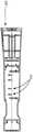
图5示出了医疗工具的示例性近侧端部,该工具包括延伸到近侧连接器中的导体束,印刷电路板(PCB)容纳在该近侧连接器内。5 illustrates an exemplary proximal end of a medical tool including a conductor bundle extending into a proximal connector within which a printed circuit board (PCB) is housed.
图6A示出了包括柔性电路条的示例性医疗工具的一部分。Figure 6A shows a portion of an exemplary medical tool including a flexible circuit strip.
图6B示出了条的示例性近侧部分。Figure 6B shows an exemplary proximal portion of a strip.
图6C示出了条的示例性近侧部分的详细视图。Figure 6C shows a detailed view of an exemplary proximal portion of a strip.
图6D示出了示例性挠性条的端视图。Figure 6D shows an end view of an exemplary flexible strip.
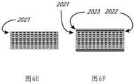
图6E示出了挠性条的示例性叠堆。Figure 6E shows an exemplary stack of flexible strips.
图6F示出了挠性条以及接地条和屏蔽条的示例性叠堆。Figure 6F shows an exemplary stack of flex strips and ground and shield strips.
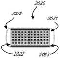
图6G示出了示例性束,该束包括围绕条以及屏蔽条和接地条的管材材料。FIG. 6G shows an exemplary bundle including tubing material surrounding the bars as well as shielding and grounding bars.
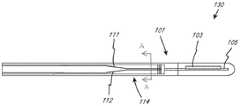
图7示出了可转向护套和医疗工具的集成系统,其中该系统经由连接器缆线连接到控制台。Figure 7 shows an integrated system of a steerable sheath and a medical tool, where the system is connected to a console via a connector cable.
图8A和图8B示出了可与本文的内部细长主体和外部细长主体或轴中的任一者一起使用的示例性柄部组件。8A and 8B illustrate exemplary handle assemblies that may be used with any of the inner and outer elongated bodies or shafts herein.
图9A示出了示例性内部细长主体或内轴的一部分。Figure 9A shows a portion of an exemplary inner elongated body or inner shaft.
图9B示出了示例性外部细长主体或外轴的一部分。Figure 9B shows a portion of an exemplary outer elongated body or shaft.
图9C示出了包括图9A和图9B的细长主体(或轴)的示例性医疗装置的一部分。Figure 9C illustrates a portion of an exemplary medical device including the elongate body (or shaft) of Figures 9A and 9B.
图9D示出了图9C的可偏转部分中的装置的剖面。Figure 9D shows a cross-section of the device in the deflectable portion of Figure 9C.
图10A示出了示例性柄部组件的一部分。Figure 10A shows a portion of an exemplary handle assembly.
图10B为示出了示例性外部细长主体(或外轴)移动子组件的分解图。Figure 10B is an exploded view showing an exemplary outer elongated body (or outer shaft) movement subassembly.
图10C示出了图57A的柄部组件的侧面剖视图。Figure 1OC shows a side cross-sectional view of the handle assembly of Figure 57A.
图11示出了包括用于第一致动器和第二致动器的旋转指示器的示例性柄部组件。11 illustrates an example handle assembly including rotation indicators for a first actuator and a second actuator.
图12A示出了包括张紧构件或展平构件的示例性柄部组件的内部部件。FIG. 12A illustrates the internal components of an exemplary handle assembly including tensioning members or flattening members.
图12B示出了(在侧视图中)包括张紧构件或展平构件的示例性柄部组件的内部部件。Figure 12B shows (in side view) the internal components of an exemplary handle assembly including tensioning members or flattening members.
图12C示出了(在相对于图12B的另一侧的侧视图中)包括张紧构件或展平构件的示例性柄部组件的内部部件。12C shows (in a side view on the other side relative to FIG. 12B ) the internal components of an exemplary handle assembly including a tensioning member or a flattening member.
图12D示出了示例性柄部壳体的内部部件,该内部部件包括被定位成有助于稳定柄部组件中的张紧构件的一个或多个引导特征结构。FIG. 12D illustrates internal components of an example handle housing including one or more guide features positioned to help stabilize a tensioning member in the handle assembly.
图12E示出了示例性柄部壳体的侧视图。Figure 12E shows a side view of an exemplary handle housing.
图12F示出了示例性柄部壳体的侧视图。Figure 12F shows a side view of an exemplary handle housing.
图13A示出了至少一部分相对于长轴扭转的示例性柔性缆线束。Figure 13A illustrates an exemplary flexible cable harness with at least a portion twisted about the major axis.
图13B示出了至少一部分相对于长轴扭转的示例性柔性缆线束。Figure 13B illustrates an exemplary flexible cable harness with at least a portion twisted about the major axis.
图13C示出了至少一部分相对于长轴扭转的示例性柔性缆线束。Figure 13C illustrates an exemplary flexible cable harness with at least a portion twisted about the major axis.
图13D示出了至少一部分相对于长轴扭转的示例性柔性缆线束。Figure 13D illustrates an exemplary flexible cable harness with at least a portion twisted about the major axis.
图13E示出了来自图13D的细节。Figure 13E shows details from Figure 13D.
具体实施方式detailed description
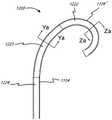
图1A示出了集成转向和医疗装置的系统的示例性实施方案。系统1000包括柄部组件1002以及转向和医疗装置部分1004。转向和医疗装置部分1004包括近侧部分1006和可转向部分1008。该系统适于使得柄部组件1002可被致动以引起可转向部分1008的转向,并且任选地可被进一步致动以引起医疗装置1010相对于转向和医疗装置部分1004的移动。在该示例性实施方案中,柄部组件1002包括第一致动器1001、第二致动器1003和第三致动器1005。第一致动器1001适于相对于柄部主体1007致动(在该示例中,旋转),以引起可转向部分1008的转向,并且具体地讲,使外部护套1102转向。在该实施方案中,可转向部分1008可转向或弯曲到在图1A中以实线示出的构型,并且也可转向到以虚线示出的构型,或其间的任何地方,并且在一些实施方案中,相反的转向功能被限制为仅仅使轴从初始弯曲构型(诸如图1A中的实线弯曲构型)拉直。本公开中的术语“转向”意指任选地经由至少一根拉线的致动而偏转或弯曲,但在一些情况下,该术语可包括轴旋转(扭转)和轴向移动。本文中的术语“拉线”是指可将张力从装置的近侧端部传输到远侧端部区域的任何元件。拉线可由实心或绞合/编织的金属线(诸如不锈钢或镍钛)构成,或者其可由优选地绞合/编织的聚合物(诸如芳族聚酰胺纤维
图1A所示的实施方案是包括集成柄部组件的设备的示例,该集成柄部组件与可转向外轴和内部医疗工具两者能够操作地连通。柄部组件被集成是因为其被组装并且构造成在封装和使用之前与外轴和内部医疗工具能够操作地连通。术语“集成”在集成柄部组件的上下文中使用时是指柄部组件,其中在医疗工具可从外轴内移除之前,柄部组件的至少一部分必须被断裂或分开。The embodiment shown in FIG. 1A is an example of a device that includes an integrated handle assembly in operative communication with both a steerable outer shaft and an inner medical tool. The handle assembly is integrated as it is assembled and configured to be in operative communication with the outer shaft and inner medical tool prior to packaging and use. The term "integrated" when used in the context of an integrated handle assembly refers to a handle assembly where at least a portion of the handle assembly must be broken or separated before the medical tool can be removed from within the outer shaft.
图1B示出转向和装置部分1004的,并且具体地讲在可转向部分1008中的示例性横截面A-A(示于图1A中)。在该实施方案中,医疗装置1010的大小和构造被设计成设置在可转向护套内。可转向护套包括外轴1102和一组拉线1104,它们轴向固定在可转向部分1008的远侧区域中。FIG. 1B shows an exemplary cross-section A-A of steering and
图1A和图1B中的医疗工具可以是例如本文的任何医疗工具,诸如超声工具。当本文使用“超声探头”时,其通常是指细长工具,该细长工具包括至少一个超声换能器以及将至少一个超声换能器电连接到细长工具的近侧区域的一个或多个导电元件。超声探头的近侧区域包括或被修改为包括至少一个近侧触点,该至少一个近侧触点与至少一个超声换能器电连通,并且可任选地经由附接到另一个装置、缆线或连接器上的电触点而被置于与另一个装置、缆线或连接器上的电触点电连通。The medical tool in Figures 1A and IB may be, for example, any medical tool herein, such as an ultrasound tool. When an "ultrasound probe" is used herein, it generally refers to an elongated tool comprising at least one ultrasonic transducer and one or more devices electrically connecting the at least one ultrasonic transducer to a proximal region of the elongated tool. a conductive element. The proximal region of the ultrasound probe includes or is modified to include at least one proximal contact in electrical communication with at least one ultrasound transducer and optionally via attachment to another device, cable, Electrical contacts on a wire or connector are placed in electrical communication with electrical contacts on another device, cable or connector.
图2示出了适于与图1A和图1B中的系统类似地起作用的示例性系统10,并且还示出了柄部组件12的示例性内部部件(内部部件被示出为虚线)。柄部组件12与外部可转向轴20和医疗工具30集成并能够操作地连通。柄部组件12包括致动器14,该致动器适于在相对于柄部主体15致动时引起可转向轴20的转向。致动器14经由设置在柄部组件12中的转向控件16与可转向轴20能够操作地连通。医疗工具30包括设置在柄部组件12内并结合到该柄部组件中的近侧部分18。致动器13与医疗工具30能够操作地连通,并且致动器13相对于柄部主体15的致动(在该示例中,旋转)经由旋转控件1215引起医疗工具30相对于外轴20的旋转。任选的第三致动器17还与医疗工具30能够操作地连通,并且在该实施方案中适于被轴向地(相对于柄部主体15)致动,以经由轴向控件1217引起医疗工具30相对于外部可转向轴20的轴向移动。FIG. 2 shows an
图2中的医疗工具可以是例如本文的任何医疗工具,诸如超声工具。The medical tool in Figure 2 may be, for example, any medical tool herein, such as an ultrasound tool.
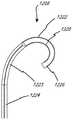
图3A至图3E表示系统1200中的可转向护套1202的护套部分1208的远侧区域的示例性实施方案。为简单起见,所示横截面仅示出外部护套1208而不示出内部工具1212。外部护套1208优选地具有复合构造,以改善从近侧端部施加到轴外部的扭矩传递,或抵抗从轴内(例如从工具1212)施加到其上的扭矩力。如图3Ai至图3Aiii所示,为了形成复合物,优选地由金属线(圆形、成对圆形或带状)和/或多根纤维(例如,芳族聚酰胺或尼龙)形成的多个编织元件1250可直接编织在薄壁(例如,0.0010"±0.0005")润滑衬里管1251(诸如PTFE或FEP材料)上。热塑性聚合物1252(诸如硬度在25D至72D范围内的Pebax,或尼龙,或其他常见导管材料)可使用热收缩管材(诸如FEP)通过热量而被层压,以使聚合物在编织元件1250和衬里管1251上方回流以形成均匀构件。热塑性聚合物1252还可具有不透射线的化合物,该化合物包括诸如铋、硫酸钡或钨之类的材料,以便在荧光镜透视检查下护套的末端对用户可见。在图3Ai至图3Aiii的实施方案中,拉线1104优选地平行于护套的可转向(可偏转)部分1222中的中心通路,并且还优选地设置在可转向护套1208的壁内形成的管腔1253中。该管腔可在热塑性聚合物管材挤出过程期间或在轴热层压熔合过程期间借助于可移除的心轴形成。拉线管腔1253可进一步通过将优选地由可移除的心轴暂时支撑的拉线管1254结合在壁内而形成。在熔合过程期间,可移除的心轴也可放置在拉线1104或1104’旁边,从而产生一定程度地椭圆化的管腔1253,在该管腔内可允许纤维拉线变平,从而为拉线的自由移动留出空间。管1254可包含PTFE、FEP、聚酰亚胺或在最高大约500℉的热层压过程期间维持其壁完整性的另一种材料。该管优选地由热塑性聚合物1252包围和支撑,该热塑性聚合物优选地抵靠管热层压。在另一个实施方案中,拉线管腔(优选地包括拉线管)结合在编织元件1250的编织物内。例如,沿一个方向延伸的编织元件1250将在拉线管腔下方经过,而沿相反方向延伸的那些编织元件将在拉线管腔上方经过。编织增强在导管操纵期间提供尺寸上更稳定的管腔,并且还有助于根据需要确保管腔的平直度。在可转向部分近侧,拉线可在外部护套1208的同一侧上平行于中心轴线朝近侧延续,诸如图3Ai至图3Aiii所示。在该实施方案和随后的其他实施方案中,可能需要在护套1208的壁内布线的附加拉线管腔内的附加拉线1104’向上穿过可转向部分1222,以拉直装置的可转向部分。该拉直拉线1104’优选地在与用于在可转向部分1222中转向(偏转)的拉线1104相对的一侧上在可转向部分1222内布线。在另一个实施方案(未示出)中,可使用两个管腔和两根拉直拉线1104’,基本上使成对的拉线1104构型成镜像。这些拉直的线还可被构造成通过在柄部内张紧较大的距离(超过刚刚拉直)而允许在相反方向上偏转。3A-3E illustrate an exemplary embodiment of a distal region of a
在使用期间,可迫使远侧导管的刚好在可转向(可偏转)部分1222近侧的部分1223基于其所用的解剖结构的约束而适形于曲线。对于将装置从腹股沟通路推进到心室中的具体实施方案,预计被迫成为曲线的部分1223的长度在5cm至25cm的范围内。在护套轴1208从近侧端部旋转期间,扭矩通过该远侧弯曲区域1223传递到导管末端。该区域1223中的装置的不均匀的横截面和/或张力可引起轴积聚并突然释放扭矩的趋势,从而在扭转时引起旋转的“抖动”或突然的抽动。为了使抖动的可能性最小化,任选的是将拉线张力和构造材料分布在弯曲区域1223的表面周围。在一个实施方案中,诸如图3Bi至图3Biii所示,拉线1104可在部分1222近侧的至少弯曲区域1223中围绕护套的中心轴线螺旋。该实施方案的拉线可在大约10cm的长度内形成完整的周向缠绕,其中该值在5cm至15cm的范围内。螺旋可仅需要存在于弯曲区域1223中,此后通过近侧部分1224(类似于1006)朝近侧继续拉直,这可使拉线管腔中的摩擦和使可转向部分1222转向(偏转)所需的相关联拉线力最小化。在继续拉直之前,螺旋还可进行最少一圈,或者使轴的整个长度螺旋。在使抖动最小化的另一个实施方案中,可能仅需要将拉线张力分布到轴的相对侧。如图3Ci至图3Cii所示,利用彼此相邻地定位在护套1208的同一侧上的两根平行拉线1104来实现可转向节段1222的偏转。在可转向节段1222近侧的弯曲区域1223和近侧部分1224(类似于1006)中,拉线被布线到轴的相对侧,每一侧与可转向节段1222中的位置成90°,以更均匀地分布张力。虽然优选的是利用柄部致动器以相等的力同时致动两根平行拉线,但在其他实施方案中,当用相等的力致动两根平行拉线时,可施加不同的力以将末端转向到所形成的平面的一侧或另一侧。在其他实施方案中,任何多根拉线能够以如图3B或图3C所示的相同构型布线,其中多根近侧拉线围绕轴圆周均匀地分布。另外,如图3Ci至图3Cii所示,拉线1104可在轴近侧部分1124长度的大部分内沿着轴的相对侧朝近侧布线,但优选地在轴的近侧端部部分附近彼此相邻地一起拉回,以允许线一起离开近侧轴的同一侧,以便于将它们一起固定到柄部部件以用于同时致动张力。During use, the
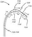
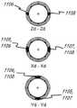
图3Di至图3Div示出了导管的远侧区域的另一个实施方案,该导管的构造类似于先前所述的构造,但替代地被构造成提供可偏转到两个不同方向的远侧可转向部分1222。如图所示,两对拉线1105/1107和1106/1108沿着近侧轴区域1224和弯曲区域1223。这类似于图3Ai至图3Aiii,不同的是线在轴的每一侧上成对。布线也可以如图3Bi至图3Bii中那样螺旋,或者是所讨论的其他构型。在远侧可转向部分1222内,线被布线成与近侧部分成90°,但也可以设想其他角度。在1222内的结合部1225处,拉线(例如,1105和1107)中的一者或多者可终止并锚定到轴,其中剩余的拉线(例如,1106和1108)继续到它们锚定的更远侧末端位置1226。该构型允许在1225和1226处终止的拉线的独立致动,使得在致动期间可形成不同的形状。图3Dii示出了被张紧以在相同方向上形成可变曲线的线1107和1108两者。图3Diii示出了被张紧以形成“S”曲线的线1107和1106。其他构型也是可能的。Figures 3Di to 3Div show another embodiment of the distal region of a catheter that is constructed similarly to that described previously, but is instead configured to provide a distally steerable surface that can be deflected into two different directions.
拉线(诸如1104和1104’)必须以将它们牢靠地附连到远侧可转向轴部分1222的壁的方式在它们的远侧端部处终止,使得它们在反复施加张力下不断裂或无牵拉。在图3E所示的优选的实施方案中,拉线1104和1104’在离开远侧拉线管腔1253时周向交织到远侧轴1222的编织线1250(示出为不具有热塑性聚合物1252)中。拉线1104或1104’中的一者或多者还可另外或替代地缠绕和/或系在编织线1250的外部周围以用于附加固定。然后可在固定点的远侧修剪编织线1250,其中交织和/或缠绕的拉线防止编织线膨胀和/或散开。还可使用诸如UV固化或氰基丙烯酸酯之类的附加粘合剂来将拉线固定到编织线。然后将拉线和编织线的编织物和/或缠绕物与热塑性聚合物层压,该热塑性聚合物在线周围的空间内熔融并冷却以将线固定在适当位置。热塑性聚合物还可具有不透射线的化合物,该化合物包括诸如铋、硫酸钡或钨之类的材料,以便在荧光镜透视检查下护套的末端对用户可见。Puller wires such as 1104 and 1104' must terminate at their distal ends in a manner that securely attaches them to the wall of distal
在另外的实施方案中,工具1212还可或另选地被构造成具有一根或多根拉线,以使末端以类似于针对外部护套1208描述的前述实施方案中的任一个实施方案的方式偏转。除了在工具1212的管状构件的壁内对拉线进行布线之外,拉线还可在管状元件1212的管腔内的导体附近被布线。拉线的致动可来自位于近侧柄部1206中的致动器。工具1212的远侧轴还可形成为特定形状(例如,弧形),使得其在离开外部护套1208的可转向部分1222的末端时弯曲成该形状。工具1212的远侧轴的刚度使得其在内部时基本上不使外部护套1208变形,但在离开时允许该外部护套弯曲。该形状可通过以下手段中的任一者或组合来设定:对聚合物材料进行热定形,使用在轴1212的内部管腔内在或轴1212的壁内的管腔内的可移动或固定形状的管心针。这样的管心针的横截面可为圆形、椭圆形或矩形,并且由不锈钢、镍钛诺或刚性聚合物诸如PEEK、Vestamid或类似物形成。外部可转向护套可另选地利用与上述类似的方法,在具有或不具有附加拉线偏转、以及具有或不具有工具轴1212的远侧部分的附加形状或偏转的情况下制成弯曲的。In additional embodiments, the
本公开的一个方面包括将系统的至少一部分与其他部件分离的方法,任选地作为重新安置过程的一部分。在一些实施方案中,医疗工具包括联接到其他电触点的一个或多个电触点,该一个或多个电触点与能量控制台电连通,并且控制台的示例是超声领域已知的。One aspect of the present disclosure includes a method of isolating at least a portion of a system from other components, optionally as part of a relocation process. In some embodiments, the medical tool includes one or more electrical contacts coupled to other electrical contacts that are in electrical communication with an energy console, examples of which are known in the ultrasound art.
图4仅示出了示例性医疗工具的一部分,诸如超声探头,其可以直接或间接电联接到能量控制台,诸如超声控制台。FIG. 4 shows only a portion of an exemplary medical tool, such as an ultrasound probe, which may be directly or indirectly electrically coupled to an energy console, such as an ultrasound console.
重新安置装置可涉及断开一个或多个近侧电触点,并且将工具部分朝远侧移出护套部分的远侧端部。在该实施方案中,工具部分1212包括至少工具外部护套或构件2010、远侧工作端部1821(其可包括至少一个超声换能器)和导体束2020。导体束2020从远侧工作端部1821延伸穿过工具外部构件2010到近侧连接器(为清楚起见,连接器和柄部机构在图18中未示出)。在一些实施方案中,医疗工具用于超声成像,任选地其中远侧工作端部1821包括安装在ASIC(专用集成电路)上的压电部件的二维(2D)阵列。Repositioning the device may involve opening the one or more proximal electrical contacts and moving the tool portion distally out of the distal end of the sheath portion. In this embodiment,
图5示出了医疗装置的仅示例性近侧端部(医疗装置在右侧示出),并且在该实施方案中,医疗装置是超声探头。医疗装置的近侧端部2015适于电联接到连接器缆线270,该连接器缆线适于直接或间接电联接到能量控制台,诸如超声能量控制台。如图5所示,柔性导体束2020从医疗工具的远侧区域(远侧区域未示出)延伸到近侧连接器2015中,刚性或柔性印刷电路板(“PCB”)2030容纳在该近侧连接器内。连接器束2020包括附接到PCB板触点2031的多个触点2024(其示例在下文描述)。来自每个触点2031的每条单独迹线连接到PCB的另一部分上(任选地更靠近PCB)的单独暴露触点2050。单独PCB迹线还可以穿过PCB上的其他可用电路。暴露的触点2050被构造用于与配合连接器缆线2070上的类似触点2060机械配合以便导电,这在概念上类似于先前描述的近侧工具连接器1990,该近侧工具连接器将工具1204连接到用户接口控制台。近侧连接器2015可结合到本文的系统、柄部、可转向护套、医疗工具等中的任一者中。Figure 5 shows only an exemplary proximal end of a medical device (the medical device is shown on the right), and in this embodiment the medical device is an ultrasound probe. The
除非本文有相反的说明,否则如本文中所使用的,术语“导体束”可与“柔性导体束”互换使用。As used herein, the term "conductor bundle" may be used interchangeably with "flexible conductor bundle" unless otherwise stated herein.
图6A和图6B示出了可包括在本文的导体束中的任一个导体束中的示例性导体条(在本文中也称为柔性电路条)2021。图6A和图6B中的实施方案是可包括在图4和图5的束2020中的导体条的示例。图6A和图6B中的实施方案可并入本文的任何其他系统中。6A and 6B illustrate exemplary conductor strips (also referred to herein as flex circuit strips) 2021 that may be included in any of the conductor bundles herein. The implementations in FIGS. 6A and 6B are examples of conductor bars that may be included in
如图6A、图6B和图6G所示,导体束2020包括多个挠性电路条,包括多迹线条2021,以及用于接地的导电条2022和用于屏蔽的导电条2023(仅示出其一部分)。每个多迹线条包括多条导电迹线2025,这可在图6B、图6C和图6D中清楚地看到。图6D至图6G中的迹线2025的数量为十二,并且图6A至图6C中的迹线的数量为十六,并且它们两者关于可使用的迹线2025的数量均是示例性的。每个条2021可以是大约0.072"宽和0.0022"厚,并且可以任选地包括十六个0.0022"宽×约0.0007"厚的导电(例如,铜)迹线,各自间隔开大约0.0022"。迹线设置在绝缘衬底层2027上,诸如聚酰亚胺衬底,并且迹线可以被覆盖层2026至少部分地覆盖,诸如可光成像的膜覆盖(“PIC”)层或其他干膜焊接掩膜(DFSM)或其他类似材料。覆盖层通常沿着束的大部分延伸,除非在近侧区域和远侧区域中的离散位置处,以便电联接。在其他实施方案中,条2021为大约0.055"宽并且包括十二条导电迹线(参见图6D至图6G)。在其他实施方案中,条2021为大约0.037"宽并且包括八条铜导电迹线。用于接地的外部条2022和用于屏蔽的外部条2023可具有类似的构造和尺寸,不同的是它们可包括单个全宽铜条。如针对2D压电阵列优化的,将需要大约七个16迹线条2021的叠堆(或者九个12迹线、或十四个8迹线),以及位于多迹线条的叠堆的每一侧上的条2022和2023中的每一者。图6E示出了具有堆叠在一起的九个条2021的示例性束2020的一部分。图6F示出了束的一部分,该束包括堆叠的九个条2021,以及接地条2022和屏蔽条2023(仅标记顶部的那些)。完整的束可任选地与(例如但不限于)约0.001"壁厚收缩管(诸如图6G中的管材2028)保持在一起。上文讨论的挠性电路尺寸和迹线的数量用于压电阵列(和/或其ASIC控制器)的特定构型,并且可根据针对特定应用而优化的阵列元件的数量和大小来改变。As shown in FIGS. 6A, 6B and 6G, the
每个挠性电路条的近侧端部具有通过在位置2024处移除覆盖层2026而暴露在大约例如3mm的长度上的导电材料(例如,镀金铜)。位置2024和本文所述的其他暴露位置通常称为“触点”。应当理解,当在该上下文中使用时,触点实际上包括多条分开的导电迹线(诸如区域位置中所示),每条导电迹线适于与其本身对应的导电元件电连通。因此,“触点”不限于意指两个导电元件之间的仅单个电连接件。虽然图6A示出了多个暴露区域2024,但图6A中的实施方案将首先在本文中描述为好像仅存在一个暴露区域(即,近侧端部处的区域2024)。条2021可被制成与用于PCB 2030上的导电迹线的配合暴露触点2031形成电连接,这在图6A至图6C中示出。在一些实施方案中,大小和间隔被设计成与多迹线条2021中的十六条迹线配合的十六条单独迹线被设置在给定触点2031内。ACF(各向异性导电膜)、焊接、导电粘合剂、机械连接或这些的任何组合可用于在条迹线和PCB触点之间实现合适的电连接(电联接)。The proximal end of each flex circuit strip has conductive material (eg, gold-plated copper) exposed over a length of about, eg, 3 mm by removing
图7示出了可转向护套1202和医疗工具1204的集成系统1200,其中系统1200经由连接器缆线2070连接到控制台4000。如前所述,诸如对于图5,工具1204包括近侧连接器2015,该近侧连接器形成与缆线2070的配合连接。如前所述,期望重新安置(例如,再处理和再使用)系统1200。进一步期望确保系统仅由原始制造商而不是非附属第三方重新安置,并且确保装置仅重新使用指定的次数。为了控制重新安置过程,将密码认证芯片(密码芯片)结合到工具1204中,优选地结合在PCB 2030上,但也可设想其他位置,诸如可转向柄部1206内或末端3000内的位置。密码芯片只能由控制认证密钥的原始制造商编程。系统1200连接到的控制台4000具有可信平台模块(TPM),该可信平台模块也具有认证密钥。在系统1200的使用期间,控制台4000能够经由密码芯片认证系统1200,并且根据需要可向芯片读取和写入信息(例如,经由EEPROM特征)。在所讨论的任何场景中,RFID芯片(优选地为加密的)可用于在控制台、连接器和装置之间读取和传输数据。FIG. 7 shows an
如本文所用,“清洁”可指任何类型的清洁,诸如但不限于:使用清洁剂和/或消毒剂的冲洗系统来清洁外轴的内部,并且任选地用小刷子进行机械擦洗;用清洁剂/消毒剂机械清洁(例如,擦拭物、刷子)外轴的外部部分和/或医疗装置轴(例如,超声探头)的外部部分,并且任选地将轴浸没在清洁剂/消毒剂的超声浴中持续指定的时间段;以及光学清洁方法,诸如包括使用UV光。如本文所用,“清洁”不是指具体的清洁过程,而是指清洁物体的总理念。As used herein, "cleaning" may refer to any type of cleaning such as, but not limited to: cleaning the inside of the outer shaft with a flush system of detergent and/or disinfectant, and optionally mechanical scrubbing with small brushes; mechanically clean (e.g., wipe, brush) the external portion of the outer shaft and/or the external portion of the medical device shaft (e.g., ultrasound probe) with an agent/disinfectant, and optionally immerse the shaft in ultrasonic waves of the cleaner/disinfectant. in a bath for a specified period of time; and optical cleaning methods, such as including the use of UV light. As used herein, "cleaning" does not refer to a specific cleaning process, but to the general idea of cleaning an object.
本文的公开内容还包括组装或重新组装本文的子组件或组件中的任一者(包括本文的柄部组件中的任一个柄部组件内的子组件中的任一个子组件)的方法。例如但不限于,此处的公开内容包括将一根或多根拉线卷在主轴支撑件中的支承表面上并且然后卷在主轴周围的方法。The disclosure herein also includes methods of assembling or reassembling the subassemblies or any of the assemblies herein, including any of the subassemblies within any of the handle assemblies herein. For example and without limitation, the disclosure herein includes methods of coiling one or more pull wires onto a bearing surface in a spindle support and then coiled around the spindle.
本文的方法还包括制造或构造本文的子组件或组件中的任一者的任何单独部件。例如,本公开包括制造柄部壳部件的方法,该柄部壳部件具有可容纳允许本文的组件或子组件按预期起作用的内部部件的特定构型(例如,引导件、壁等)。The methods herein also include making or constructing any individual part of any of the subassemblies or assemblies herein. For example, the present disclosure includes methods of making handle housing components having specific configurations (eg, guides, walls, etc.) that can accommodate internal components that allow the assemblies or subassemblies herein to function as intended.
不管所标记的参考标号,本文的柄部组件、医疗工具、可转向护套和电连接件都可在系统中以彼此的任何组合一起使用。Regardless of the reference numerals marked, the handle assemblies, medical tools, steerable sheaths, and electrical connections herein may be used in any combination with each other in a system.
以下美国专利参考文献中的任一者中的任何技术(包括超声和转向技术)都可以结合到本文的医疗工具、装置、系统或其使用方法中的任一者中,这些专利参考文献的公开内容以引用方式并入本文:6100626、6537217、6559389、7257051、7297118、7331927、7338450、7451650、7451650、7527591、7527592、7569015、7621028、7731516、7740584、7766833、7783339、7791252、7791252、7819802、7824335、7966058、8057397、8096951、8207652、8207652、8213693、8364242、8428690、8451155、8527032、8659212、8721553、8727993、8742646、8742646、8776335、8790262、8933613、8978216、8989842、9055883、9439625、9575165、9639056和20080287783。Any of the techniques, including ultrasound and steering techniques, in any of the following U.S. patent references, which disclose内容以引用方式并入本文:6100626、6537217、6559389、7257051、7297118、7331927、7338450、7451650、7451650、7527591、7527592、7569015、7621028、7731516、7740584、7766833、7783339、7791252、7791252、7819802、7824335、 7966058、8057397、8096951、8207652、8207652、8213693、8364242、8428690、8451155、8527032、8659212、8721553、8727993、8742646、8742646、8776335、8790262、8933613、8978216、8989842、9055883、9439625、9575165、9639056和20080287783。
以上任何合适的公开内容均可并入以下实施方案中的任一个实施方案中。例如,除非有相反的具体说明,否则装置、系统及制造和使用方法的各方面并入本文,并且可并入以下实施方案中的任一个实施方案中。Any suitable disclosure above may be incorporated into any of the following embodiments. For example, aspects of devices, systems, and methods of making and using are incorporated herein, and can be incorporated into any of the following embodiments, unless specifically stated to the contrary.
图8A和图8B示出了可以与外轴131和内轴132能够操作地连通的仅示例性的柄部组件。在该示例性具体实施中,柄部组件120包括柄部主体123、第一致动器121和第二致动器122,该柄部主体具有可由用户抓握的外表面。致动器121可以与外轴131能够操作地连通,并且致动器122可以与内轴132能够操作地连通。致动器121适于相对于柄部主体123(并且相对于第二致动器122)旋转和轴向移动。这允许致动器121引起医疗工具103的轴向移动和医疗工具103相对于内轴132的远侧端部的旋转。第二致动器122适于相对于柄部主体123致动(例如,在该实施方案中为旋转),以引起内轴132的偏转。例如,柄部组件可具有内部部件,该内部部件与拉线的近侧端部交接,使得致动器122的致动张紧一根或多根拉线以引起内轴的偏转。在该实施方案中,致动器121位于致动器122的远侧,但在其他设计中,其相对位置可颠倒。图8B示出了致动器121已相对于其在图8A中的位置朝远侧推进之后的柄部组件120。该远侧推进引起外轴131朝远侧推进,并且因此引起医疗工具朝远侧推进。致动器121可类似地相对于其在图8B中的位置朝近侧回缩。下面进一步描述的张紧构件关于朝近侧回缩的致动器121来提及。8A and 8B show only exemplary handle assemblies that may be in operative communication with
在其他设计中,致动器121可以与内轴能够操作地连通,并且致动器122可以与外轴能够操作地连通。In other designs,
如本文所述,外轴可相对于可偏转的内轴轴向移动。外轴可由沿外轴的至少一部分的长度在刚度(例如,硬度)上变化的材料节段构成。例如,在第二部分远侧的第一部分可具有比第二部分低的硬度。由于外轴可相对于可偏转的内轴轴向移动,并且由于外轴的刚度可沿着其长度变化,因此可通过控制外轴的轴向位置(相对于内轴)来选择性地控制整个装置的偏转,包括程度(或量)。因此,外轴的轴向移动可选择性地控制装置的偏转。例如,用户(例如,医师)可通过相对于内轴轴向地移动外轴来改变或控制沿着装置的长度(从远侧端部测量)发生弯曲的位置。另外,例如,根据外轴相对于可偏转的内轴的相对位置,外轴中刚度变化的节段可允许或多或少的偏转。例如,与当内轴在外轴具有较小刚度的区域处偏转时相比,内轴在外轴具有相对较高刚度的区域处偏转可导致较小偏转。As described herein, the outer shaft is axially movable relative to the deflectable inner shaft. The outer shaft may be comprised of segments of material that vary in stiffness (eg, hardness) along at least a portion of the length of the outer shaft. For example, the first portion distal to the second portion may have a lower stiffness than the second portion. Since the outer shaft is axially movable relative to the deflectable inner shaft, and since the stiffness of the outer shaft can vary along its length, the overall Deflection of a device, including degree (or amount). Thus, axial movement of the outer shaft selectively controls deflection of the device. For example, a user (eg, a physician) can change or control where along the length of the device (measured from the distal end) the bend occurs by axially moving the outer shaft relative to the inner shaft. Additionally, segments of varying stiffness in the outer shaft may allow more or less deflection, eg, depending on the relative position of the outer shaft relative to the deflectable inner shaft. For example, deflecting the inner shaft at a region of relatively higher stiffness of the outer shaft may result in less deflection than when the inner shaft deflects at a region of less stiffness of the outer shaft.
图9C示出了示例性设备医疗设备130,该医疗设备包括细长内轴132(参见图9A)和细长外轴131(参见图9B)。医疗设备130在本文中也可称为“导管”或包括至少一个细长轴的其他医疗装置。FIG. 9C illustrates an exemplary device
图9D示出了图9C中的组件中所示的剖面A-A,该组件为装置的可偏转节段中的节段。图9A至图9C的部件被类似地标记。如在图9D中可见,拉线111和112彼此非常接近并且与拉直拉线116成约180度。Figure 9D shows section A-A shown in the assembly in Figure 9C, which is a segment of the deflectable segments of the device. Components of FIGS. 9A-9C are similarly labeled. As can be seen in FIG. 9D , pull
还如图9D所示,细长内轴132包括两层编织材料119,并且拉线至少在该节段的位置处基本上夹在两层编织材料之间。环形空间118允许任选润滑剂的移动自由度和空间。内轴132可由例如但不限于聚合物材料诸如Pebax制成,任选地具有润滑添加剂。内轴132可包括衬里125,诸如PTFE衬里。柔性缆线束105可由一层或多层绝缘体126(诸如PTFE绝缘体)围绕。外轴131可包含聚合物材料127,诸如Pebax。外轴131还可包括径向内部衬里128,诸如PTFE衬里。拉线(例如,111、112、116)中的任一根拉线可设置在具有衬里诸如PTFE衬里129的管腔中。As also shown in FIG. 9D , the elongated
医疗设备130(或细长轴132和细长轴131中的任一者,单独地)可与本文的柄部组件中的任一个柄部组件(包括图8A和图8B所示的柄部组件120)能够操作地连通。The medical device 130 (or any of the
图10A-10C和图11示出了可与本文的医疗装置中的任一个医疗装置(包括超声探头)能够操作地连通的附加示例性柄部组件。例如,图10A-10C所示的示例性柄部组件可联接到(直接或间接地)图9A-9D所示的医疗设备130并且与该医疗设备能够操作地连通。在具体实施方案中,细长外轴131和细长内轴132两者联接到图10A-10C所示的柄部组件并与该柄部组件能够操作地连通。10A-10C and 11 illustrate additional exemplary handle assemblies that may be in operative communication with any of the medical devices herein, including an ultrasound probe. For example, the exemplary handle assembly shown in FIGS. 10A-10C may be coupled (directly or indirectly) to and in operative communication with the
图10A-10C和图11中的柄部组件与图8A和图8BB中所示的柄部组件、单独部件和子组件具有一些相似性。除非有相反的说明,否则可结合到图10A-C中的柄部组件中的来自图8A和图8B的概念、特征结构和使用方法出于所有目的据此以引用方式并入到图10A-C中所示和相对于图10A-C所述的柄部组件的公开内容中。相似地,出于所有目的,可结合到本文的其他柄部组件中的图10A-C中所示和所述的概念、特征结构和使用方法据此以引用方式并入到本文阐述的柄部组件中的任一个的公开内容中。The handle assembly in FIGS. 10A-10C and 11 has some similarities to the handle assembly, individual components, and subassemblies shown in FIGS. 8A and 8BB. Unless stated to the contrary, the concepts, features and methods of use from FIGS. 8A and 8B that may be incorporated into the handle assembly in FIGS. 10A-C are hereby incorporated by reference into FIGS. 10A-C for all purposes. In the disclosure of the handle assembly shown in C and described with respect to FIGS. 10A-C . Similarly, the concepts, features, and methods of use shown and described in FIGS. 10A-C that may be incorporated into other handle assemblies herein are hereby incorporated by reference into the handle set forth herein for all purposes in the disclosure of any of the components.
图10A是柄部组件140的侧视图,其中柄部主体141的一部分被移除,使得可以看到柄部组件的一些内部部件。柄部组件140包括第一致动器143和第二致动器142,并且在该实施方案中,第一致动器143在第二致动器142的远侧。第一致动器143可同时相对于柄部主体和相对于第二致动器(在该实施方案中为致动器142)轴向移动和旋转。第一致动器143与外部细长主体诸如外轴131(参见图9B)能够操作地连通。致动器143的轴向移动(朝远侧或朝近侧)引起外轴131的轴向移动,然而致动器143的旋转引起外轴的旋转。第二致动器142与内轴诸如内轴132(参见图9A)能够操作地连通。第二致动器142的致动(在该实施方案中为旋转)引起内轴的偏转。在该实施方案中,可旋转且可轴向移动的致动器(即,第一致动器143)与外轴能够操作地连通。10A is a side view of the
第一致动器143联接到图10B中的分解图所示的细长外轴移动组件150,使得第一致动器143的移动引起组件150的移动。细长外轴移动组件150类似地联接到细长外轴,使得第一致动器的移动也引起细长外轴的移动。在该实施方案中,外部细长轴在其被插入到通道156中之后附接到可移除部件153。可移除部件153和通道156被构造成使得可移除部件153在插入到通道156中时受到该通道的至少一个内表面的约束。细长外轴移动组件150也包括固定到第一致动器的远侧头部部分151。细长外轴移动组件150也包括与本文所述的旋转限制机构类似的旋转限制机构,该旋转限制机构限制第一致动器143的旋转,并且由此限制外部细长轴的旋转。上文涉及旋转限制子组件、功能和用途的任何公开内容出于所有目的并入该实施方案中,并且可并入该设计和类似设计中。在旋转期间,部件157(参见图10B)与部件161相互作用,并且部件162与部件158相互作用。这两组部件的物理相互作用将旋转限制到期望的旋转极限,例如,将旋转限制到外部主体的旋转的至多630度(在其他实施方案中,允许的旋转可大于630度,诸如至多720度并包括720度)。The
如果期望例如在使用之后清洁外轴,则可移除部件153可与外轴分离以允许该外轴从柄部组件移除并且在重新插入和重新附接到可移除部件153或新的可移除部件(如果部件153被损坏或断裂)之前进行清洁。If it is desired to clean the outer shaft, for example after use, the
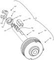
柄部组件140还包括内轴偏转组件146,该内轴偏转组件与第二致动器142能够操作地连通。内轴偏转组件146包括中心齿轮147,该中心齿轮适于并被构造成在第二致动器142旋转时旋转。中心齿轮147经由齿轮接口与第一主轴148和第二主轴149接合,使得中心齿轮147的旋转引起主轴沿相反方向的旋转。内轴偏转组件146(包括主轴)比细长外部主体移动组件150进一步朝近侧延伸。内轴延伸穿过外轴,并且在柄部组件150内比外轴进一步朝近侧延伸。这允许作为内轴的一部分的一根或多根拉线径向向外延伸并且与卷筒160交接。The
细长外轴移动组件150和细长内轴移动组件146之间不存在相互作用允许内部细长轴和外部细长轴由第一致动器143和第二致动器142独立地控制。The absence of interaction between the elongated outer
柄部组件140还包括设置在柄部主体141内的印刷电路板(“PCB”)170,该PCB与缆线束电连通,该缆线束诸如图53中的柔性缆线束105,或本文中与医疗工具(诸如超声换能器)连通的缆线束中的任一个缆线束。Handle assembly 140 also includes a printed circuit board (“PCB”) 170 disposed within
柄部组件140还包括旋转指示器180,该旋转指示器可用于向用户显示第一致动器和第二致动器中的至少一者相对于原始或中性位置旋转的程度。第一致动器143可包括旋转指示器181,当第一致动器143处于中性位置时,该旋转指示器沿着轴线与旋转指示器180对准,如图11所示。当第一致动器143旋转时,旋转指示器181相对于旋转指示器180沿其延伸的轴线旋转,这使得用户能够在视觉上理解第一致动器143以及因此外轴相对于中性位置在一定程度上旋转。类似地,第二致动器142也可具有旋转指示器182,当第二致动器142处于中性位置时,该旋转指示器沿着轴线与旋转指示器180对准,如图11所示。当第二致动器143旋转时,旋转指示器182相对于旋转指示器180沿其延伸的轴线旋转,这使得用户能够在视觉上理解第二致动器143以及因此内轴相对于其中性位置在一定程度上偏转。The
在一些另选实施方案中,柄部组件可包括一个或多个传感器以跟踪外轴发生了多少旋转,或内轴发生了多少偏转。在一些实施方案中,柄部组件可包括用于每个致动器的编码器。In some alternative embodiments, the handle assembly may include one or more sensors to track how much the outer shaft is rotated, or how much the inner shaft is deflected. In some embodiments, the handle assembly can include an encoder for each actuator.
在包括外轴和内轴的本文的实施方案中的任一个实施方案中,装置可在内轴和外轴之间包括一种或多种润滑剂,以使得通过减小内轴和外轴两者之间的摩擦更容易使该内轴和外轴相对于彼此移动。如果医疗装置需要清洁以重复使用,则可在清洁过程之后在内轴和外轴之间添加附加润滑剂。In any of the embodiments herein that include an outer shaft and an inner shaft, the device may include one or more lubricants between the inner shaft and the outer shaft such that by reducing the Friction between the two makes it easier for the inner and outer shafts to move relative to each other. If the medical device needs to be cleaned for reuse, additional lubricant can be added between the inner and outer shafts after the cleaning process.
在本文的一些实施方案中,医疗装置可包括柔性构件,诸如柔性导体束(其在本文中可称为导体束、柔性束或它们的其他类似衍生物),其联接到医疗装置的远侧区域(例如,探头末端)并且从该远侧区域朝向该医疗装置的近侧区域延伸(参见例如示例性图4-6G所示的导体束2020;或来自图9B的束105)。探头末端可包括与柔性导体束电连通的超声换能器。在本文的一些实施方案中(例如,图9A-11),探头末端和导体束可通过柄部致动器(例如,如图10A所示的致动器143)的致动而轴向(朝近侧和/或朝远侧)移位。在一些情况下,导体束设置在细长构件(例如,可转向内部细长主体132;或细长构件131)内,并且当探头末端向远侧推进或朝近侧缩回时相对于该细长构件轴向移动。当远侧区域(例如,超声探头)和导体束朝近侧回缩(在朝远侧推进之后)时,由于束和例如其中设置有导体束的细长构件(例如,可转向内轴132)之间的摩擦,导体束可趋于在其远侧端部附近或邻近该远侧端部折叠、聚拢或以其他方式弯曲。如果医疗装置处于直的构型以及如果医疗装置具有一定程度的弯曲(例如,在从直的构型或线性构型偏转之后),则可发生聚拢。In some embodiments herein, a medical device may include a flexible member, such as a flexible conductor bundle (which may be referred to herein as a conductor bundle, flexible bundle, or other similar derivatives thereof), coupled to a distal region of the medical device (eg, probe tip) and extend from the distal region toward a proximal region of the medical device (see, eg,
为了降低聚拢或弯曲趋势的程度或甚至完全防止聚拢或弯曲的趋势,本文的医疗装置中的任一个可包括结构张紧构件,该结构张紧构件适于并被构造成在导体束联接到远侧医疗工具的位置附近的位置处对柔性构件(诸如柔性导体束)施加或保持张力。通过张紧柔性构件,可最小化或甚至防止柔性构件的折叠或聚拢。当在该上下文中使用时,“张紧”构件适于并被构造成通过在远侧探头朝近侧回缩时朝近侧移动柔性导体束的至少远侧部分来减少柔性导体的一个或多个远侧区域聚拢(与没有张紧构件的装置相比)。在一些实施方案中,结构张紧构件(例如,张紧棒)可以物理地固定到柔性导体束(例如,直接或间接附接)。一般来讲,本文的张紧构件与柔性构件(例如,柔性导体束)能够操作地连通,使得张紧构件的移动或致动向柔性构件施加一定的力,并且可引起柔性构件的移动(例如,在近侧)。在一些示例性实施方案中,结构张紧构件可设置在医疗装置的柄部组件中或由医疗装置的柄部组件承载。在这种情况下,结构张紧构件可以是单个部件或单独部件的组件。In order to reduce the degree of bunching or bending tendency or even prevent bunching or bending tendency altogether, any of the medical devices herein may include a structural tension member adapted and configured to connect the conductor bundle to the remote Tension is applied or maintained to the flexible member, such as the flexible conductor bundle, at a location near the location of the side medical tool. By tensioning the flexible member, folding or bunching of the flexible member can be minimized or even prevented. As used in this context, a "tensioning" member is adapted and configured to reduce one or more of the flexible conductor bundles by moving at least a distal portion of the flexible conductor bundle proximally as the distal probe is retracted proximally. The two distal regions are brought together (compared to devices without tensioning members). In some embodiments, structural tension members (eg, tension rods) may be physically secured to the flexible conductor bundle (eg, directly or indirectly attached). Generally, the tension members herein are in operative communication with a flexible member (e.g., a flexible conductor bundle) such that movement or actuation of the tension member applies a force to the flexible member and can cause movement of the flexible member (e.g., on the proximal side). In some exemplary embodiments, a structural tension member may be disposed in or carried by a handle assembly of a medical device. In this case, the structural tension member may be a single component or an assembly of separate components.
图12A-12F示出了可结合到本文任何合适的医疗装置中的示例性医疗装置的柄部组件部分。例如,图12A-12F中的柄部组件可以为在其远侧端部处或其远侧端部附近包括医疗工具(例如,超声成像探头)的医疗装置的一部分,其示例在本文中有所描述。本文的任何其他实施方案或特征结构以引用方式并入图12A-12F所示的示例性柄部组件中。12A-12F illustrate a handle assembly portion of an exemplary medical device that may be incorporated into any suitable medical device herein. For example, the handle assembly in FIGS. 12A-12F may be part of a medical device that includes a medical tool (e.g., an ultrasound imaging probe) at or near its distal end, examples of which are described herein. describe. Any other embodiments or features herein are incorporated by reference into the exemplary handle assembly shown in FIGS. 12A-12F .
示例性柄部组件310包括第一致动器314和第二致动器322,其中第一致动器314在近侧致动器322的远侧。第一致动器314适于并被构造成相对于第二致动器322轴向(朝远侧和朝近侧)移动(并且任选地也可相对于该第二致动器旋转),并且可与细长主体(例如,131或132)能够操作地连通,该细长主体可包括位于远侧区域中的医疗工具(例如,103)。柄部组件310(包括致动器)可结合来自本文任何其他柄部组件的任何相关公开内容。柄部组件310是其一部分的医疗装置还包括柔性构件(例如,图9B中的柔性导体束105),该柔性构件在第一远侧位置处牢固地联接到(直接或间接地)医疗工具(例如,如图9B和9C所示,其中医疗工具103固定到柔性构件105)并且从该医疗工具朝向柄部组件310朝近侧延伸。柔性构件可为柔性导体束并且可延伸到柄部组件310中,如图所示。柔性构件的一部分设置在细长主体的外表面内(例如,在131和/或132内)。医疗装置还包括张紧构件,该张紧构件在第二位置316处固定到柔性构件,该第二位置邻近第一位置(在该上下文中,“第一位置”可被称为第一远侧位置或其衍生物)。图12A示出了示例性张紧构件312,而图12A中的参考标号312也指向张紧构件的任选细长刚性构件(在该实施方案中,细长刚性构件是线性的并且轴向延伸)。张紧构件312适于并且被构造成当医疗工具朝近侧回缩时张紧柔性构件。这在本文中可被称为向柔性构件施加张力,或张紧柔性构件,或保持柔性构件中的张力。在该示例性实施方案中,张紧构件312适于并被构造成在医疗工具朝近侧回缩时张紧柔性构件,这在该实施方案中在第一致动器314从其在图12A-C所示的位置朝近侧回缩时发生。当医疗装置处于直的构型时并且当医疗装置处于非直的(线性)构型时,诸如当装置可偏转或弯曲时,本文的张紧构件可施加张力。The
在该实施方案中,张紧构件312(其可包括图12A中所示的张紧棒)在位置316处固定(例如,直接附接)到柔性导体束,在该实施方案中,该位置在柄部组件内部。张紧构件可另选地在不处于柄部内的位置处(诸如在柄部的外部,诸如在外轴和内轴中的一者或两者的内部)固定到柔性构件。在该实施方案中,张紧构件也相对于第一致动器314轴向固定,使得第一致动器314的轴向移动引起张紧构件312的轴向移动(其可以1:1移动比率)。因为张紧构件312也固定到柔性构件(例如,在位置316处),所以张紧构件312的轴向移动也导致柔性构件在位置316处的轴向移动。通过将张紧构件312固定到柔性构件,当第一致动器314朝近侧回缩时,柔性构件在张紧构件固定到柔性构件的位置的远侧张紧,这防止了柔性构件在其靠近或邻近医疗工具的远侧区域处折叠或聚拢(或者与没有张紧构件的装置相比,至少减小了折叠/聚拢的程度)。In this embodiment, tensioning members 312 (which may include tensioning rods as shown in FIG. 12A ) are secured (eg, directly attached) to the flexible conductor bundle at
柔性构件可包括柔性导体束,诸如本文的柔性导体束中的任一者。在图12A-F中,张紧构件包括具有固定长度的刚性细长构件(在图12A中通常称为312)。如图所示的刚性张紧构件具有大致纵向轴线,在该实施方案中,该大致纵向轴线与医疗装置的纵向轴线和/或柄部组件的纵向轴线平行。刚性张紧构件可以由多种材料制成,诸如刚性塑性构件。The flexible member may comprise a flexible conductor bundle, such as any of the flexible conductor bundles herein. In Figures 12A-F, the tensioning member comprises a rigid elongated member (generally referred to as 312 in Figure 12A) of fixed length. The rigid tensioning member as shown has a generally longitudinal axis which, in this embodiment, is parallel to the longitudinal axis of the medical device and/or the longitudinal axis of the handle assembly. Rigid tension members can be made from a variety of materials, such as rigid plastic members.
本文的张紧构件可确保医疗工具行进的距离与柔性构件上第一位置和第二位置之间的任何点行进的距离相同。本文的张紧构件可确保医疗工具行进的距离与张紧构件固定到柔性构件的位置(例如,图12A中的位置316)行进的距离相同。The tensioning member herein ensures that the medical tool travels the same distance as any point on the flexible member between the first position and the second position. The tensioning member herein can ensure that the medical tool travels the same distance as the location where the tensioning member is secured to the flexible member (eg,
当医疗工具朝近侧回缩时(当医疗装置是直的构型时),张紧构件和柔性构件之间的固定关系使柔性构件在第一位置和第二位置之间保持基本上平坦或直的构型。在该上下文中,展平构型可包括其中柔性构件也可被扭转(即,柔性构件可以为平坦的并且仍然被扭转,但不聚拢/折叠)的实施方案。如本文所用,展平构型指示柔性构件没有折叠或聚拢。When the medical tool is retracted proximally (when the medical device is in a straight configuration), the fixed relationship between the tensioning member and the flexible member keeps the flexible member substantially flat or flat between the first position and the second position. Straight configuration. In this context, a flattened configuration can include embodiments where the flexible member can also be twisted (ie, the flexible member can be flat and still twisted, but not bunched/folded). As used herein, a flattened configuration indicates that the flexible member is not folded or gathered.
其中结合有张紧构件的医疗装置也可以是可转向的或可偏转的。本文的张紧构件可以适于并被构造成即使医疗装置(包括柔性构件)处于非直的(例如,偏转、转向、弯曲)构型,也可以向柔性构件施加张力。当本公开是指在柔性构件中保持基本上展平构型时,其是指医疗装置可处于直的构型的情况,这不必定是该情况,诸如当医疗装置已被转向、弯曲或偏转时。The medical device in which the tensioning member is incorporated may also be steerable or deflectable. The tensioning members herein can be adapted and configured to apply tension to the flexible member even when the medical device (including the flexible member) is in a non-straight (eg, deflected, turned, bent) configuration. When the present disclosure refers to maintaining a substantially flattened configuration in a flexible member, it refers to situations where the medical device may be in a straight configuration, which is not necessarily the case, such as when the medical device has been steered, bent or deflected Time.
当医疗工具朝近侧回缩时,张紧构件和本文的柔性构件之间的固定关系防止柔性构件在第一位置和第二位置之间形成折叠(即,弯曲或聚拢)。在该上下文中,折叠、弯曲和聚拢包括柔性构件的第一区域,该第一区域与柔性构件的第二区域轴向重叠,并且还包括柔性构件的大致弯曲和聚拢,诸如柔性构件的不平坦并且例如形成弯曲、弯曲区域和/或来回曲折的区域。The fixed relationship between the tensioning member and the flexible member herein prevents the flexible member from forming a fold (ie, bending or bunching) between the first position and the second position when the medical tool is retracted proximally. In this context, folding, bending and gathering includes a first region of the flexible member axially overlapping a second region of the flexible member and also includes general bending and gathering of the flexible member, such as unevenness of the flexible member And, for example, bends, curved regions and/or meandering regions are formed.
柔性构件可以具有平坦的顶部表面和底部表面(例如,具有一个或多个平坦表面的导体束),并且任选地,张紧构件可固定到顶部表面和底部表面中的至少一个。例如,图6A-6G示出了具有平坦或大致平坦的第一表面和第二表面(例如,顶部表面和底部表面)的柔性构件,并且张紧构件可固定到平坦或大致平坦的表面中的一者或两者(例如,诸如在位置316处)。它们可使用多种技术固定,诸如使用粘合剂、焊接或其他粘结技术。The flexible member may have planar top and bottom surfaces (eg, a conductor bundle having one or more planar surfaces), and optionally, the tension member may be secured to at least one of the top and bottom surfaces. For example, FIGS. 6A-6G illustrate flexible members having flat or substantially flat first and second surfaces (e.g., top and bottom surfaces), and tensioning members may be secured to the flat or substantially flat surfaces. One or both (eg, such as at location 316). They can be secured using a variety of techniques, such as using adhesives, welding or other bonding techniques.
张紧构件可与柄部致动器能够操作地连通(直接地或间接地),使得致动器的轴向移动使张紧构件轴向移动。柄部致动器还可适于并被构造成旋转(例如,致动器314)以引起医疗工具的旋转,并且任选地,其中致动器的旋转不引起张紧构件的旋转。因此,张紧构件可适于在致动器轴向移动时轴向移动,但在致动器旋转时不旋转。这可通过张紧构件与致动器操作地连通(直接地或间接地)的方式来实现。The tensioning member may be in operative communication (directly or indirectly) with the handle actuator such that axial movement of the actuator moves the tensioning member axially. The handle actuator may also be adapted and configured to rotate (eg, actuator 314 ) to cause rotation of the medical tool, and optionally, wherein rotation of the actuator does not cause rotation of the tensioning member. Thus, the tensioning member may be adapted to move axially when the actuator moves axially, but not to rotate when the actuator rotates. This may be accomplished by the tensioning member being in operative communication (either directly or indirectly) with the actuator.
医疗装置可包括内部细长主体(例如,132),该内部细长主体包括其中设置柔性构件的至少一部分的管腔。内部细长主体可以是可独立转向的,诸如利用单独的可独立地致动的柄部致动器(例如,致动器322)。其中医疗装置包括内部构件和外部构件、该内部构件可独立地控制(例如,轴向地和旋转地)的本文其他实施方案的各方面完全结合在本文实施方案中的任一个中。The medical device can include an inner elongated body (eg, 132 ) including a lumen in which at least a portion of the flexible member is disposed. The inner elongated body may be independently steerable, such as with a separate independently actuatable handle actuator (eg, actuator 322 ). Aspects of the other embodiments herein wherein the medical device includes an inner member and an outer member, the inner member being independently controllable (eg, axially and rotationally) are fully incorporated in any of the embodiments herein.
柔性构件可联接到柄部组件中的印刷电路板(例如,如图12A所示的321“板”)。张紧构件可联接到印刷电路板近侧的柔性构件。在另选的实施方案中,张紧构件可联接到印刷电路板远侧的柔性构件。The flexible member may be coupled to a printed circuit board (eg, 321 "Board" as shown in FIG. 12A ) in the handle assembly. The tension member may be coupled to the flexible member proximal the printed circuit board. In an alternative embodiment, the tension member may be coupled to a flexible member distal to the printed circuit board.
图12A-12F是医疗装置的一部分的示例,其包括细长外部主体(例如,131),该细长外部主体包括在细长主体的远侧区域中的探头末端;柔性导体束(例如,105),该柔性导体束在第一位置处牢固地联接到探头末端(在图9B和图9C中示出)并且从医疗工具朝近侧延伸并进入柄部组件中,柔性构件设置在细长主体的外表面内;内部细长主体(例如,131),该内部细长主体的至少一部分设置在细长外部主体内,该内部细长主体任选地可转向,其中柔性导体束的至少一部分设置在内部细长主体内并且被构造成可相对于该内部细长主体轴向移动;张紧构件,该张紧构件在柄部组件中的第二位置处固定到该柔性构件,张紧构件适于并被构造成当探头末端朝近侧缩回时在该柔性构件上施加张力。如本文所用,探头末端可包括一个或多个超声换能器。12A-12F are examples of a portion of a medical device comprising an elongated outer body (e.g., 131) including a probe tip in a distal region of the elongated body; a flexible conductor bundle (e.g., 105 ), the flexible conductor bundle is firmly coupled to the probe tip (shown in FIGS. 9B and 9C ) at a first position and extends proximally from the medical tool and into the handle assembly, the flexible member being disposed on the elongated body Inner elongated body (for example, 131), at least a portion of the inner elongated body is disposed within the elongated outer body, the inner elongated body is optionally steerable, wherein at least a portion of the flexible conductor bundle is disposed Within the inner elongated body and configured to be axially movable relative to the inner elongated body; a tension member secured to the flexible member at a second location in the handle assembly, the tension member adapted to and configured to exert tension on the flexible member when the probe tip is retracted proximally. As used herein, a probe tip may include one or more ultrasound transducers.
图12E-F示出了柄部外部壳体320的一半,其中两个形成柄部组件310的外表面的一部分。柄部壳体320包括径向向内延伸的特征结构315,该结构适于与控制张紧构件312的移动的控制器交接。特征结构315可包括引导件,该引导件被构造成在一个或多个位置处与张紧构件交接并且帮助稳定张紧构件。12E-F show half of the handle
可适当地集成到柄部组件310中的本文任何其他实施方案中的任何其他柄部组件部件以引用方式并入本文。Any other handle assembly components in any other embodiments herein that may be suitably integrated into
在本文的任何实施方案和权利要求中,短语“张紧构件”可替换为“拉直构件”、“展平构件”或其衍生物。如本文所述,拉直构件或展平构件是指当医疗装置处于拉直构型时在柔性构件中保持基本上直的或展平构型,并且不需要装置总是具有拉直构型。因此,即使柔性构件不一定被置于张力下,其也仍可由于拉直构件而沿其长度的至少一部分保持处于拉直(即,不折叠构型)。例如,图12A中的构件312是拉直构件的示例,即使其也用作张紧构件。这适用于本文所述、所示和所要求保护的所有张紧构件。在本文的一些实施方案中,“构件”可为拉直构件(或展平构件)并且还可用作张紧构件。另外,本文的短语“张紧构件”可替换为“防折叠构件”、“防弯曲构件”、“防聚拢构件”或其衍生物。In any of the embodiments and claims herein, the phrase "tensioning member" may be replaced with "straightening member", "flattening member" or derivatives thereof. As used herein, a straightening member or a flattening member refers to maintaining a substantially straight or flattened configuration in a flexible member when the medical device is in the straightened configuration, and the device is not required to always have the straightened configuration. Thus, even though the flexible member is not necessarily placed under tension, it can remain in a straightened (ie, unfolded configuration) along at least a portion of its length due to the straightening member. For example,
上述公开内容描述了在一些实施方案中,柔性构件诸如导体束2010可沿其长度的一部分扭转。例如,导体束可扭转以沿医疗装置的长度的一部分提供更平衡的横截面。导体束可仅在将经历偏转的医疗装置的一部分中扭转。The above disclosure describes that in some embodiments, a flexible member such as the
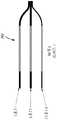
图13A-13E示出了包括扭转的柔性构件(诸如柔性导体束)的示例性医疗装置的一部分。图13A-E中的实施方案可与本文所述的任何其他合适的特征结构和/或医疗装置结合。13A-13E illustrate a portion of an exemplary medical device including a twisted flexible member, such as a flexible conductor bundle. The embodiments in Figures 13A-E may be combined with any other suitable features and/or medical devices described herein.
图13A-E中所示的医疗装置的部分330包括位于远侧区域处的医疗工具332、联接到该医疗工具并且从该医疗工具朝近侧延伸的柔性构件331、以及包括多个电连接器的近侧端部区域333。柔性构件331可为柔性导体束,诸如本文的束中任一者。医疗工具332可包括超声成像换能器339。柔性导体束331具有导体束在其中扭转的区域338,扭转区域338具有远侧端部和近侧端部。柔性导体束331还包括在扭转区域334远侧的未扭转的区域336和在扭转区域336近侧的未扭转的区域340。医疗工具332可联接到外轴,诸如图9B所示的外轴131。The
扭转区域338从其远侧端部到其近侧端部的长度可变化,并且在一些实施方案中为5-15cm,诸如8-15cm,诸如11cm。在其上形成完整圈的长度可变化很大,诸如1-5cm,诸如3cm。The
在扭转区域的长度上的扭转次数也可变化,诸如但不限于7-9次完全扭转。The number of twists over the length of the twisted region may also vary, such as but not limited to 7-9 full twists.
形成柔性构件(例如,柔性导体束)的扭转区域的示例性方式是在远侧端部(例如,探头末端)处将柔性构件联接到医疗工具。然后可在柔性导体束上方推进薄的PET热收缩节段。可将装置的一部分保持在适当位置,同时将另一部分扭转至期望的圈数以形成扭转区域。在维持扭转构型的同时,PET可在扭转束区域上热收缩。随后可添加附加的PET层。然后可将细长构件(例如,轴131)放置在束(包括扭转区域)上,并且可将细长构件粘结到医疗工具。An exemplary way of forming the torsional region of a flexible member (eg, a flexible conductor bundle) is to couple the flexible member to a medical tool at a distal end (eg, probe tip). A thin PET heat shrink segment can then be advanced over the flexible conductor bundle. One part of the device can be held in place while the other part is twisted the desired number of turns to create the twisted region. While maintaining the twisted configuration, PET can heat shrink over the twisted bundle area. Additional PET layers can then be added. The elongate member (eg, shaft 131 ) can then be placed on the bundle (including the twisted region), and the elongate member can be bonded to the medical tool.
Claims (11)
Applications Claiming Priority (3)
| Application Number | Priority Date | Filing Date | Title |
|---|---|---|---|
| US201962839520P | 2019-04-26 | 2019-04-26 | |
| US62/839520 | 2019-04-26 | ||
| PCT/US2020/030114WO2020220033A1 (en) | 2019-04-26 | 2020-04-27 | Medical tool positioning devices, systems, and methods of use and manufacture |
Publications (2)
| Publication Number | Publication Date |
|---|---|
| CN113873948A CN113873948A (en) | 2021-12-31 |
| CN113873948Btrue CN113873948B (en) | 2023-01-13 |
Family
ID=72940804
Family Applications (1)
| Application Number | Title | Priority Date | Filing Date |
|---|---|---|---|
| CN202080031587.6AActiveCN113873948B (en) | 2019-04-26 | 2020-04-27 | Medical tool positioning device, system, and methods of use and manufacture |
Country Status (6)
| Country | Link |
|---|---|
| US (1) | US20220168041A1 (en) |
| EP (1) | EP3958744B1 (en) |
| JP (1) | JP7512308B2 (en) |
| CN (1) | CN113873948B (en) |
| IL (1) | IL287476A (en) |
| WO (1) | WO2020220033A1 (en) |
Families Citing this family (4)
| Publication number | Priority date | Publication date | Assignee | Title |
|---|---|---|---|---|
| WO2021089374A1 (en)* | 2019-11-05 | 2021-05-14 | Biotronik Se & Co. Kg | Catheter tube for a steerable catheter, and method for implanting an implantable medical device by means of a steerable catheter |
| US11931066B2 (en)* | 2021-02-25 | 2024-03-19 | Avent, Inc. | Directly connected smart invasive medical device assembly |
| PL441943A1 (en) | 2022-08-05 | 2024-02-12 | Sniper Spółka Z Ograniczoną Odpowiedzialnością | Endovascular catheter |
| WO2024224267A1 (en)* | 2023-04-25 | 2024-10-31 | Nuvera Medical, Inc. | Medical tool positioning device and systems |
Family Cites Families (13)
| Publication number | Priority date | Publication date | Assignee | Title |
|---|---|---|---|---|
| US5441483A (en)* | 1992-11-16 | 1995-08-15 | Avitall; Boaz | Catheter deflection control |
| JPH10225457A (en)* | 1997-02-14 | 1998-08-25 | Olympus Optical Co Ltd | Ultrasonic endoscope |
| WO2001036017A2 (en)* | 1999-11-05 | 2001-05-25 | Zynergy Cardiovascular, Inc. | Catheter assembly having integral electrical connector disposed therein |
| GB2365127A (en)* | 2000-07-20 | 2002-02-13 | Jomed Imaging Ltd | Catheter |
| JP4339830B2 (en) | 2005-08-03 | 2009-10-07 | オリンパスメディカルシステムズ株式会社 | Ultrasound endoscope |
| EP1849414B1 (en)* | 2005-02-07 | 2012-03-14 | Olympus Medical Systems Corp. | Ultrasound endoscope |
| JP4388485B2 (en) | 2005-02-07 | 2009-12-24 | オリンパスメディカルシステムズ株式会社 | Electronic radial type ultrasound endoscope |
| US9289147B2 (en)* | 2010-05-11 | 2016-03-22 | St. Jude Medical, Atrial Fibrillation Division, Inc. | Multi-directional flexible wire harness for medical devices |
| US10070793B2 (en)* | 2010-11-27 | 2018-09-11 | Securus Medical Group, Inc. | Ablation and temperature measurement devices |
| WO2013154684A1 (en) | 2012-04-09 | 2013-10-17 | St. Jude Medical, Atrial Fibrillation Division, Inc. | Multi-directional flexible wire harness for medical devices |
| KR101560344B1 (en)* | 2014-06-16 | 2015-10-19 | 동국대학교 산학협력단 | Pullback system |
| CA3030011A1 (en) | 2016-07-19 | 2018-01-25 | Shifamed Holdings, Llc | Medical devices and methods of use |
| EP3599977A4 (en)* | 2017-03-30 | 2020-12-30 | Shifamed Holdings, LLC | Medical tool positioning devices, systems, and methods of use and manufacture |
- 2020
- 2020-04-27WOPCT/US2020/030114patent/WO2020220033A1/ennot_activeCeased
- 2020-04-27USUS17/602,362patent/US20220168041A1/enactivePending
- 2020-04-27EPEP20795763.0Apatent/EP3958744B1/enactiveActive
- 2020-04-27CNCN202080031587.6Apatent/CN113873948B/enactiveActive
- 2020-04-27JPJP2021563291Apatent/JP7512308B2/enactiveActive
- 2021
- 2021-10-21ILIL287476Apatent/IL287476A/enunknown
Also Published As
| Publication number | Publication date |
|---|---|
| EP3958744B1 (en) | 2025-06-18 |
| JP2022532992A (en) | 2022-07-21 |
| EP3958744C0 (en) | 2025-06-18 |
| WO2020220033A1 (en) | 2020-10-29 |
| US20220168041A1 (en) | 2022-06-02 |
| EP3958744A1 (en) | 2022-03-02 |
| CN113873948A (en) | 2021-12-31 |
| IL287476A (en) | 2021-12-01 |
| JP7512308B2 (en) | 2024-07-08 |
| EP3958744A4 (en) | 2023-01-25 |
Similar Documents
| Publication | Publication Date | Title |
|---|---|---|
| CN113873948B (en) | Medical tool positioning device, system, and methods of use and manufacture | |
| JP7220240B2 (en) | Steerable medical device with strain relief elements | |
| JP7648100B2 (en) | Cable routing and assembly for medical device handles | |
| EP3880285B1 (en) | Medical tool positioning devices | |
| EP4151157B1 (en) | Medical tool shaft | |
| US20240358351A1 (en) | Medical tool positioning devices, systems, and methods of use and manufacture | |
| EP4570188A1 (en) | Over-the-wire medical tool positioning devices, systems, and methods of use and manufacture | |
| US20250204889A1 (en) | Medical tool positioning devices, systems, and methods of use and manufacture | |
| WO2024224267A1 (en) | Medical tool positioning device and systems | |
| US20250255578A1 (en) | Cable routing and assemblies for medical device handles | |
| JP3601351B2 (en) | Flexible part of endoscope |
Legal Events
| Date | Code | Title | Description |
|---|---|---|---|
| PB01 | Publication | ||
| PB01 | Publication | ||
| SE01 | Entry into force of request for substantive examination | ||
| SE01 | Entry into force of request for substantive examination | ||
| GR01 | Patent grant | ||
| GR01 | Patent grant |