CN113873059B - Rotating shaft mechanism and foldable mobile terminal - Google Patents
Rotating shaft mechanism and foldable mobile terminalDownload PDFInfo
- Publication number
- CN113873059B CN113873059BCN202010617287.8ACN202010617287ACN113873059BCN 113873059 BCN113873059 BCN 113873059BCN 202010617287 ACN202010617287 ACN 202010617287ACN 113873059 BCN113873059 BCN 113873059B
- Authority
- CN
- China
- Prior art keywords
- main shaft
- rotating
- shaft
- assembly
- main
- Prior art date
- Legal status (The legal status is an assumption and is not a legal conclusion. Google has not performed a legal analysis and makes no representation as to the accuracy of the status listed.)
- Active
Links
Images


Classifications
- H—ELECTRICITY
- H04—ELECTRIC COMMUNICATION TECHNIQUE
- H04M—TELEPHONIC COMMUNICATION
- H04M1/00—Substation equipment, e.g. for use by subscribers
- H04M1/02—Constructional features of telephone sets
- H04M1/0202—Portable telephone sets, e.g. cordless phones, mobile phones or bar type handsets
- H04M1/0206—Portable telephones comprising a plurality of mechanically joined movable body parts, e.g. hinged housings
- H04M1/0208—Portable telephones comprising a plurality of mechanically joined movable body parts, e.g. hinged housings characterized by the relative motions of the body parts
- H04M1/0214—Foldable telephones, i.e. with body parts pivoting to an open position around an axis parallel to the plane they define in closed position
- H04M1/0216—Foldable in one direction, i.e. using a one degree of freedom hinge
- H—ELECTRICITY
- H04—ELECTRIC COMMUNICATION TECHNIQUE
- H04M—TELEPHONIC COMMUNICATION
- H04M1/00—Substation equipment, e.g. for use by subscribers
- H04M1/02—Constructional features of telephone sets
- H—ELECTRICITY
- H04—ELECTRIC COMMUNICATION TECHNIQUE
- H04M—TELEPHONIC COMMUNICATION
- H04M1/00—Substation equipment, e.g. for use by subscribers
- H04M1/02—Constructional features of telephone sets
- H04M1/0202—Portable telephone sets, e.g. cordless phones, mobile phones or bar type handsets
- H04M1/026—Details of the structure or mounting of specific components
- H04M1/0266—Details of the structure or mounting of specific components for a display module assembly
- H04M1/0268—Details of the structure or mounting of specific components for a display module assembly including a flexible display panel
Landscapes
- Engineering & Computer Science (AREA)
- Signal Processing (AREA)
- Telephone Set Structure (AREA)
Abstract
Translated fromChinese
Description
Translated fromChinese技术领域technical field
本申请实施例涉及终端技术领域,尤其涉及一种转轴机构及可折叠移动终端。The embodiments of the present application relate to the technical field of terminals, and in particular to a hinge mechanism and a foldable mobile terminal.
背景技术Background technique
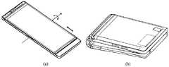
随着柔性屏技术的发展,柔性屏应用逐渐增多,可折叠移动终端即为柔性屏技术的一种应用。可折叠移动终端的柔性显示屏可以连续可折叠,图1为现有技术中的一种柔性屏的状态图,如图1中的(a)示出了柔性屏在展开状态时的状态图,图1中的(b)示出了柔性屏在折叠状态的状态图,其中,阴影部分为折弯部分。可折叠移动终端在由展开状态到折叠状态的过程中,柔性屏的折弯部分会受到来自可折叠移动终端的壳体的挤压力,并因此产生过度弯折变形,因此可能会造成柔性屏被挤压,例如,对比图1中的(a)和图1中的(b)可知,柔性屏折弯部分的外侧长度从L1到L3,两者等长;而内侧长度从L2需变化为L4,L4远小于L2,内侧长度变化量很大,这样将会对柔性屏产生挤压作用。反之,可折叠移动终端在由折叠状态到展开状态的过程中,壳体将会对柔性屏产生拉扯作用。With the development of flexible screen technology, flexible screen applications are gradually increasing, and foldable mobile terminals are an application of flexible screen technology. The flexible display screen of a foldable mobile terminal can be folded continuously. FIG. 1 is a state diagram of a flexible screen in the prior art, and (a) in FIG. 1 shows a state diagram of the flexible screen in an unfolded state. (b) in FIG. 1 shows a state diagram of the flexible screen in a folded state, wherein the shaded part is a bent part. When the foldable mobile terminal is from the unfolded state to the folded state, the bending part of the flexible screen will be squeezed from the shell of the foldable mobile terminal, and excessive bending deformation will occur, which may cause the flexible screen For example, comparing (a) in Figure 1 and (b) in Figure 1, it can be seen that the outer length of the flexible screen bending part is from L1 to L3, and both are equal in length; while the inner length needs to be changed from L2 to L4, L4 is much smaller than L2, and the inner length changes greatly, which will squeeze the flexible screen. Conversely, when the foldable mobile terminal changes from the folded state to the unfolded state, the housing will pull the flexible screen.
图2为现有技术中的一种可折叠移动终端的状态图,图2中的(a)为展开状态图,图2中的(b)为折叠状态图。如图2中的(a)所示,两个壳体之间通过一个转轴结构连接,柔性屏设置在两个壳体与转轴结构的同一表面,柔性屏与壳体之间有较大的间距。可折叠移动终端在由展开状态至折叠状态的过程中,柔性屏的中间区域会跟随转轴结构产生拱起的弯曲变形,柔性屏会相对壳体滑动,这样可避免柔性屏过度弯折变形而不会挤压柔性屏。然而,在使用过程中,柔性屏与壳体之间会相对滑动,这样会增加柔性屏的损坏风险,对柔性屏的要求较高。如图2中的(b)所示,在折叠状态的柔性屏从侧面看类似于球棒状,可折叠移动终端的厚度差异很大。折叠状态时两侧壳体之间有一个很大的间隙,容易掉入细长条的物体而造成柔性屏的损伤。Fig. 2 is a state diagram of a foldable mobile terminal in the prior art, (a) in Fig. 2 is an unfolded state diagram, and Fig. 2 (b) is a folded state diagram. As shown in (a) in Figure 2, the two housings are connected by a rotating shaft structure, the flexible screen is arranged on the same surface of the two housings and the rotating shaft structure, and there is a large distance between the flexible screen and the housing . When the foldable mobile terminal is from the unfolded state to the folded state, the middle area of the flexible screen will follow the shaft structure to produce an arched bending deformation, and the flexible screen will slide relative to the housing, which can avoid excessive bending and deformation of the flexible screen Will squeeze the flexible screen. However, during use, the flexible screen and the housing will slide relative to each other, which will increase the risk of damage to the flexible screen, and has higher requirements on the flexible screen. As shown in (b) of FIG. 2 , the flexible screen in the folded state looks like a bat from the side, and the thickness of the foldable mobile terminal varies greatly. In the folded state, there is a large gap between the shells on both sides, and it is easy to fall into slender objects and cause damage to the flexible screen.
如何实现可折叠移动终端展开及折叠过程中不拉扯和挤压柔性屏,并且实现可折叠移动转动在折叠状态时厚度差异较小且无较大的间隙,是亟需解决的技术问题。How to realize that the foldable mobile terminal does not pull and squeeze the flexible screen during the unfolding and folding process, and realize that the thickness difference is small and there is no large gap when the foldable mobile terminal is in the folded state, which is a technical problem that needs to be solved urgently.
发明内容Contents of the invention
本申请实施例涉及一种转轴机构及可折叠移动终端,以实现可折叠移动终端展开及折叠过程中不拉扯和挤压柔性屏,并且实现可折叠移动转动在折叠状态时厚度差异较小且无较大的间隙。The embodiment of the present application relates to a hinge mechanism and a foldable mobile terminal, so as to realize that the foldable mobile terminal does not pull and squeeze the flexible screen during the unfolding and folding process, and realize that the thickness difference of the foldable mobile terminal is small and no Larger gaps.
为了解决上述技术问题,本申请实施例提供如下技术方案:In order to solve the above technical problems, the embodiments of the present application provide the following technical solutions:
第一方面,本申请实施例提供一种转轴机构,可应用于具有柔性屏的移动终端中。转轴机构包括:主轴、成对布置的转动组件、以及设置在主轴两侧的支撑板。每对转动组件沿垂直于主轴的轴线方向分设于主轴的两侧,每个转动组件包括一个或多个摆臂,摆臂与主轴的内壁之间销轴连接。一对支撑板设置在主轴两侧,位于主轴同一侧的支撑板与转动组件对应设置。其中,每个支撑板的一端与主轴转动连接,相对另一端与转动组件滑动连接并可相对转动。或者,每个支撑板的一端与主轴滑动连接并可相对转动,相对另一端与转动组件转动连接。在位于主轴两侧的转动组件相对转动至第一位置时,转动组件带动对应的支撑板转动至第二位置,位于主轴两侧的支撑板与主轴之间形成容纳空间。In a first aspect, the embodiment of the present application provides a hinge mechanism, which can be applied to a mobile terminal with a flexible screen. The rotating shaft mechanism includes: a main shaft, rotating assemblies arranged in pairs, and support plates arranged on both sides of the main shaft. Each pair of rotating assemblies is arranged on both sides of the main shaft in a direction perpendicular to the axis of the main shaft. Each rotating assembly includes one or more swing arms connected with the inner wall of the main shaft by pins. A pair of support plates are arranged on both sides of the main shaft, and the support plates on the same side of the main shaft are arranged correspondingly to the rotating assembly. Wherein, one end of each support plate is rotatably connected with the main shaft, and the opposite end is slidably connected with the rotating assembly and can rotate relatively. Alternatively, one end of each support plate is slidably connected to the main shaft and can rotate relatively, and the opposite end is rotatably connected to the rotating assembly. When the rotating assemblies located on both sides of the main shaft are relatively rotated to the first position, the rotating assembly drives the corresponding supporting plate to rotate to the second position, and an accommodation space is formed between the supporting plates located on both sides of the main shaft and the main shaft.
其中,第一位置是指在转轴机构完全折叠状态时转动组件所在位置,此时,主轴两侧的转动组件相互靠近,两侧的转动组件上与移动终端壳体固定的固定面大致平行。第二位置是指在转轴机构完全折叠状态时支撑板所在位置,此时,主轴两侧的支撑板相互靠近,两侧的支撑板在靠近主轴位置的间距比较宽,在远离主轴位置的间距比较窄。Wherein, the first position refers to the position of the rotating assembly when the rotating shaft mechanism is fully folded. At this time, the rotating assemblies on both sides of the main shaft are close to each other, and the rotating assemblies on both sides are roughly parallel to the fixed surface fixed to the mobile terminal housing. The second position refers to the position of the support plate when the rotating shaft mechanism is fully folded. At this time, the support plates on both sides of the main shaft are close to each other, and the distance between the support plates on both sides is relatively wide when it is close to the main shaft, and the distance between the support plates is relatively wide when it is far away from the main shaft. narrow.
本申请实施例提供的转轴机构,在主轴的两侧均布置有转动组件与支撑板,转动组件的摆臂与主轴的内壁之间销轴连接。支撑板连接于主轴和转动组件之间,这样在转动组件相对主轴转动时,转动组件将会带动支撑板相对主轴转动。其中,在主轴两侧的转动组件转动至第一位置时,转动组件将会带动两侧的支撑板转动至第二位置,两侧的支撑板在靠近主轴位置的间距比较宽,在远离主轴位置的间距比较窄,两侧支撑板之间上部间距小而下部间距大,形成一个内凹的容纳空间,以容纳柔性屏部分区域。在主轴两侧的转动组件转动展开时,转动组件带动对应的支撑板转动展开,支撑板可支撑在转动组件上,主轴与支撑板可共同支撑柔性屏部分区域,支撑效果好。In the rotating shaft mechanism provided in the embodiment of the present application, a rotating assembly and a support plate are arranged on both sides of the main shaft, and the swing arm of the rotating assembly is connected with the inner wall of the main shaft by a pin. The supporting plate is connected between the main shaft and the rotating assembly, so that when the rotating assembly rotates relative to the main shaft, the rotating assembly will drive the supporting plate to rotate relative to the main shaft. Wherein, when the rotating assembly on both sides of the main shaft rotates to the first position, the rotating assembly will drive the support plates on both sides to rotate to the second position. The distance between the support plates on both sides is relatively narrow, and the distance between the upper part and the lower part of the support plates on both sides is small, forming a concave accommodation space to accommodate part of the flexible screen. When the rotating components on both sides of the main shaft rotate and expand, the rotating components drive the corresponding support plates to rotate and expand. The support plates can be supported on the rotating components. The main shaft and the support plates can jointly support a part of the flexible screen, and the supporting effect is good.
将上述转轴机构应用到可折叠移动终端上,也就是将转轴机构连接在两个壳体之间,位于主轴同一侧的转动组件固定到对应的壳体上。移动终端由展开状态至折叠状态的过程中,柔性屏的中间区域逐渐弯曲且截面形成水滴状,由于主轴两侧的支撑板与主轴之间形成的容纳空间可容纳该柔性屏的水滴状区域,这样就不会挤压柔性屏且不起拱。反之,在折叠状态至展开状态的过程中,也不会拉扯到柔性屏。在折叠与展开的过程中,柔性屏也不会相对壳体滑动,降低了柔性屏失效的风险,提高了柔性屏的可靠性。采用本申请实施例转轴机构的移动终端,主轴两侧的转动组件的摆臂与主轴的内壁之间销轴连接,采用双轴的方式实现两个壳体的连接,移动终端在折叠状态时的厚度差异较小,两个壳体之间无较大的间隙,降低细长条物体掉入间隙而造成柔性屏损伤的可能性。The above-mentioned rotating shaft mechanism is applied to the foldable mobile terminal, that is, the rotating shaft mechanism is connected between two housings, and the rotating components located on the same side of the main shaft are fixed to the corresponding housings. When the mobile terminal is from the unfolded state to the folded state, the middle area of the flexible screen is gradually bent and the cross-section forms a drop shape. Since the accommodation space formed between the support plates on both sides of the main shaft and the main shaft can accommodate the water drop-shaped area of the flexible screen, In this way, the flexible screen will not be squeezed and there will be no arching. Conversely, the flexible screen will not be pulled during the process from the folded state to the unfolded state. In the process of folding and unfolding, the flexible screen will not slide relative to the casing, which reduces the risk of failure of the flexible screen and improves the reliability of the flexible screen. In the mobile terminal adopting the rotating shaft mechanism of the embodiment of the present application, the swing arms of the rotating components on both sides of the main shaft are pinned to the inner wall of the main shaft, and the connection of the two housings is realized in a biaxial manner. When the mobile terminal is in the folded state, the The difference in thickness is small, and there is no large gap between the two shells, which reduces the possibility of damage to the flexible screen caused by slender objects falling into the gap.
将上述转轴机构应用到可折叠移动终端上,成对的转动组件的摆臂与主轴的内壁之间销轴连接,位于主轴同一侧的转动组件固定于对应的壳体上,采用双轴的方式实现两个壳体的连接,两个壳体可实现折叠与展开动作。移动终端处于完全折叠状态时,从外部看该移动终端,只看到两个壳体之间连接有主轴,而看不到两个壳体的连接位置存在缺口。相比于现有移动终端两个壳体之间采用单轴的连接方式,本申请实施例提供的转轴机构采用双轴连接,单个转动组件相对主轴的转角可以更小,这样单个转动组件与主轴之间连接位置的结构体积可以更小,移动终端在完全展开状态时,转轴机构并不会过多突出壳体。The above-mentioned rotating shaft mechanism is applied to the foldable mobile terminal. The swing arms of the paired rotating components are pinned to the inner wall of the main shaft, and the rotating components located on the same side of the main shaft are fixed on the corresponding housing in a biaxial manner. The connection of the two shells is realized, and the two shells can realize folding and unfolding actions. When the mobile terminal is in a fully folded state, looking at the mobile terminal from the outside, only the main shaft is connected between the two housings, but no gap exists at the connection position of the two housings. Compared with the single-axis connection between the two shells of the existing mobile terminal, the shaft mechanism provided by the embodiment of the present application adopts a double-axis connection, and the rotation angle of a single rotating component relative to the main shaft can be smaller, so that the single rotating component and the main shaft The structural volume of the connecting position can be smaller, and when the mobile terminal is in a fully unfolded state, the rotating shaft mechanism does not protrude too much from the housing.
结合第一方面,在第一方面的第一种可能的实现方式中,一对转动组件的摆臂转动所绕的轴线有两根,一对支撑板相对主轴的转动轴线有两根,将一对支撑板相对主轴的转动轴线设置在一对转动组件的摆臂转动所绕的轴线的两侧。在主轴两侧的转动组件转动至第一位置时,每个转动组件将会带动两侧的支撑板转动至第二位置,两侧的支撑板在靠近主轴位置的间距比较宽,在远离主轴位置的间距比较窄,两侧支撑板之间上部间距小而下部间距大,形成一个体积更大的内凹的容纳空间,以便于容纳柔性屏的水滴状区域。In combination with the first aspect, in the first possible implementation of the first aspect, there are two axes around which the swing arms of the pair of rotating assemblies rotate, and there are two supporting plates relative to the axis of rotation of the main shaft. The rotation axis of the support plate relative to the main shaft is arranged on both sides of the axis around which the swing arms of the pair of rotation assemblies rotate. When the rotating components on both sides of the main shaft rotate to the first position, each rotating component will drive the supporting plates on both sides to rotate to the second position. The distance between the support plates on both sides is relatively narrow, and the distance between the upper part and the lower part of the support plates on both sides is small, forming a larger concave accommodation space, so as to accommodate the drop-shaped area of the flexible screen.
结合第一方面或第一方面的第一种可能的实现方式,在第一方面的第二种可能的实现方式中,每个摆臂上设有连接孔,主轴的内壁上设有转动圆轴,转动圆轴枢接于连接孔。在主轴包括主外轴与主内轴时,转动圆轴可设置在主外轴或主内轴上。通过使转动圆轴枢接于连接孔的方式,可实现摆臂与主轴之间可靠稳定的转动连接。In combination with the first aspect or the first possible implementation of the first aspect, in the second possible implementation of the first aspect, each swing arm is provided with a connection hole, and the inner wall of the main shaft is provided with a rotating shaft , the rotating circular shaft is pivotally connected to the connecting hole. When the main shaft includes a main outer shaft and a main inner shaft, the rotating circular shaft can be arranged on the main outer shaft or the main inner shaft. A reliable and stable rotational connection between the swing arm and the main shaft can be realized by pivotally connecting the rotating circular shaft to the connecting hole.
结合第一方面的第二种可能的实现方式,在第一方面的第三种可能的实现方式中,转动圆轴设置于主轴的轴线方向的端部内壁,每个摆臂靠近主轴的端部设置。将销轴连接的结构设置在主轴端部,占用主轴的内部空间较小,使得主轴内部空间较大,可容置更多的零件。无需如现有移动终端在连接两个壳体之间的转轴壳外表面设置避让孔,无需在转轴壳的外表面覆盖柔性遮蔽件以遮蔽转轴壳的避让孔,并且无需设置使柔性遮蔽件随动的其它机构。本实施例的转轴机构中的主轴具有完整的外观,摆臂与主轴的端部内壁之间销轴连接,结构简单,成本较低。In combination with the second possible implementation of the first aspect, in the third possible implementation of the first aspect, the rotating circular shaft is arranged on the inner wall at the end of the main shaft in the axial direction, and each swing arm is close to the end of the main shaft set up. The pin-shaft connection structure is arranged at the end of the main shaft, which occupies less internal space of the main shaft, makes the internal space of the main shaft larger, and can accommodate more parts. There is no need to set avoidance holes on the outer surface of the shaft shell connecting the two housings as in the existing mobile terminal, there is no need to cover the outer surface of the shaft shell with a flexible shield to cover the avoidance hole of the shaft shell, and there is no need to set the flexible shield to follow Other agencies that move. The main shaft in the rotating shaft mechanism of this embodiment has a complete appearance, and the swing arm is connected with the inner wall of the end of the main shaft with pins, so the structure is simple and the cost is low.
结合第一方面或第一方面的第一种可能的实现方式,在第一方面的第四种可能的实现方式中,每个摆臂上设有转动圆轴,主轴的内壁上设有连接孔,转动圆轴枢接于连接孔。在主轴包括主外轴与主内轴时,连接孔可设置在主外轴或主内轴上。通过使转动圆轴枢接于连接孔的方式,可实现摆臂与主轴之间可靠稳定的转动连接。In combination with the first aspect or the first possible implementation of the first aspect, in the fourth possible implementation of the first aspect, each swing arm is provided with a rotating shaft, and the inner wall of the main shaft is provided with a connecting hole , the rotating circular shaft is pivotally connected to the connecting hole. When the main shaft includes a main outer shaft and a main inner shaft, the connecting hole can be arranged on the main outer shaft or the main inner shaft. A reliable and stable rotational connection between the swing arm and the main shaft can be realized by pivotally connecting the rotating circular shaft to the connecting hole.
结合第一方面的第四种可能的实现方式,在第一方面的第五种可能的实现方式中,连接孔设置于主轴的轴线方向的端部内壁,摆臂靠近主轴的端部设置。本实施例中将连接孔设置于主轴的轴线方向的端部,该销轴连接的结构占用主轴的内部空间较小,主轴具有完整的外观,结构简单。With reference to the fourth possible implementation of the first aspect, in a fifth possible implementation of the first aspect, the connection hole is disposed on the inner wall of the end of the main shaft in the axial direction, and the swing arm is disposed near the end of the main shaft. In this embodiment, the connecting hole is arranged at the end of the main shaft in the axial direction. The pin-shaft connection structure occupies less internal space of the main shaft, and the main shaft has a complete appearance and a simple structure.
结合第一方面至第一方面的第五种可能的实现方式中任一项,在第一方面的第六种可能的实现方式中,主轴上设有与每个摆臂对应的圆弧槽,每个摆臂上设有滑动装配在圆弧槽的圆弧臂;圆弧臂的轴线与摆臂转动所绕的轴线重合。通过使圆弧臂与圆弧槽滑动连接,圆弧臂的轴线与摆臂轴线同轴,提升摆臂与主轴之间转动连接的可靠性。With reference to any one of the first aspect to the fifth possible implementation manner of the first aspect, in the sixth possible implementation manner of the first aspect, an arc groove corresponding to each swing arm is provided on the main shaft, Each swing arm is provided with an arc arm slidingly fitted in the arc groove; the axis of the arc arm coincides with the axis around which the swing arm rotates. By slidingly connecting the arc arm to the arc groove, the axis of the arc arm is coaxial with the axis of the swing arm, thereby improving the reliability of the rotational connection between the swing arm and the main shaft.
结合第一方面的第六种可能的实现方式,在第一方面的第七种可能的实现方式中,主轴包括主外轴和主内轴,圆弧槽可设置在主外轴的端部内壁上;或,圆弧槽可设置在主内轴和主外轴上。将摆臂上的圆弧臂与主轴的圆弧槽连接,再将主外轴和主内轴装配好,圆弧臂滑动装配在圆弧槽内,使摆臂与主轴转动连接更平稳。In combination with the sixth possible implementation of the first aspect, in the seventh possible implementation of the first aspect, the main shaft includes a main outer shaft and a main inner shaft, and arc grooves can be provided on the inner wall at the end of the main outer shaft or, arc grooves may be provided on the main inner shaft and the main outer shaft. Connect the arc arm on the swing arm with the arc groove of the main shaft, and then assemble the main outer shaft and the main inner shaft. The arc arm is slidably fitted in the arc groove to make the rotation connection between the swing arm and the main shaft more stable.
结合第一方面至第一方面的第七种可能的实现方式中任一项,在第一方面的第八种可能的实现方式中,主轴上设有与每个摆臂对应的弧形槽,每个摆臂上设有滑动装配在弧形槽的导向柱;弧形槽的轴线与摆臂转动所绕的轴线重合。通过使导向柱与弧形槽滑动连接,弧形槽轴线与摆臂轴线同轴,提升摆臂与主轴之间转动连接的可靠性。With reference to any one of the first aspect to the seventh possible implementation manner of the first aspect, in the eighth possible implementation manner of the first aspect, an arc-shaped groove corresponding to each swing arm is provided on the main shaft, Each swing arm is provided with a guide column slidingly fitted in the arc-shaped groove; the axis of the arc-shaped groove coincides with the axis around which the swing arm rotates. By slidingly connecting the guide column with the arc-shaped slot, the axis of the arc-shaped slot is coaxial with the axis of the swing arm, thereby improving the reliability of the rotational connection between the swing arm and the main shaft.
结合第一方面的第八种可能的实现方式,在第一方面的第九种可能的实现方式中,主轴包括主外轴和主内轴,弧形槽可设置在主内轴上。将摆臂上的导向柱与主轴的弧形槽连接,再将主外轴和主内轴装配好,导向柱滑动装配在弧形槽内,使摆臂与主轴转动连接更平稳。With reference to the eighth possible implementation manner of the first aspect, in a ninth possible implementation manner of the first aspect, the main shaft includes a main outer shaft and a main inner shaft, and arc-shaped grooves may be provided on the main inner shaft. Connect the guide column on the swing arm with the arc groove of the main shaft, and then assemble the main outer shaft and the main inner shaft. The guide post is slidably fitted in the arc groove, so that the rotation connection between the swing arm and the main shaft is more stable.
结合第一方面至第一方面的第九种可能的实现方式中任一项,在第一方面的第十种可能的实现方式中,将每个支撑板的一端与主轴转动连接,每个支撑板的相对另一端与转动组件滑动连接并可相对转动。在实现支撑板与转动组件滑动连接并可相对转动时,支撑板的远离主轴的一端设有第一滑动销轴,转动组件设有第一滑槽,第一滑动销轴滑动装配在第一滑槽。在转动组件相对主轴转动时,第一滑动销轴与第一滑槽滑动连接,转动组件将会带动支撑板相对主轴转动。In combination with any one of the first aspect to the ninth possible implementation manner of the first aspect, in the tenth possible implementation manner of the first aspect, one end of each support plate is rotatably connected to the main shaft, and each support plate The opposite other end of the plate is slidably connected with the rotating assembly and can rotate relatively. When the support plate and the rotating assembly are slidably connected and relatively rotatable, the end of the support plate away from the main shaft is provided with a first sliding pin, the rotating assembly is provided with a first chute, and the first sliding pin is slidably fitted on the first slide. groove. When the rotating assembly rotates relative to the main shaft, the first sliding pin is slidably connected to the first chute, and the rotating assembly will drive the support plate to rotate relative to the main shaft.
结合第一方面至第一方面的第九种可能的实现方式中任一项,在第一方面的第十一种可能的实现方式中,将每个支撑板的一端与主轴滑动连接并可相对转动,每个支撑板的相对另一端与转动组件转动连接。在实现支撑板与主轴滑动连接并可相对转动时,支撑板靠近主轴的一端设有第二滑动销轴,主轴设有第二滑槽,第二滑动销轴滑动装配在第二滑槽。在转动组件相对主轴转动时,第二滑动销轴与第二滑槽滑动连接,转动组件将会带动支撑板相对主轴转动与滑动。With reference to any one of the first aspect to the ninth possible implementation manner of the first aspect, in the eleventh possible implementation manner of the first aspect, one end of each support plate is slidably connected to the main shaft and can be relatively Rotate, the opposite end of each support plate is rotatably connected with the rotating assembly. When the support plate and the main shaft are slidably connected and relatively rotatable, the end of the support plate close to the main shaft is provided with a second sliding pin, the main shaft is provided with a second chute, and the second sliding pin is slidably fitted in the second chute. When the rotating assembly rotates relative to the main shaft, the second sliding pin is slidably connected to the second chute, and the rotating assembly will drive the support plate to rotate and slide relative to the main shaft.
结合第一方面至第一方面的第十一种可能的实现方式中任一项,在第一方面的第十二种可能的实现方式中,在主轴与每个支撑板之间设置保护板,每个保护板沿垂直于主轴的轴线方向分设于主轴的两侧,排线设置在保护板的底面以降低排线弯折损坏的可能性。在设置保护板时,位于主轴同侧的保护板与支撑板对应设置。每个保护板具有第一端及与该第一端相对的第二端,第一端与主轴转动连接,第二端与保护板对应的支撑板滑动连接。在每个转动组件相对主轴转动的过程中,转动组件带动支撑板相对主轴转动,而支撑板带动保护板相对主轴转动。在主轴两侧的转动组件转动且相互靠近的过程中,主轴两侧的支撑板将会相对主轴转动并相互靠近,支撑板会带动保护板转动,保护板并不会影响容纳空间内的柔性屏的中间区域。在主轴两侧的支撑板完全展开时,支撑板、保护板与主轴的上表面平齐,共同支撑柔性屏完全展开后的中间区域。With reference to any one of the first aspect to the eleventh possible implementation manner of the first aspect, in a twelfth possible implementation manner of the first aspect, a protection plate is provided between the main shaft and each support plate, Each protective plate is arranged on both sides of the main shaft along the axis perpendicular to the main shaft, and the cable is arranged on the bottom surface of the protective plate to reduce the possibility of bending and damage of the cable. When setting the protection plate, the protection plate on the same side of the main shaft is set correspondingly to the supporting plate. Each protection plate has a first end and a second end opposite to the first end, the first end is rotatably connected to the main shaft, and the second end is slidably connected to the support plate corresponding to the protection plate. During the rotation of each rotating assembly relative to the main shaft, the rotating assembly drives the supporting plate to rotate relative to the main shaft, and the supporting plate drives the protection plate to rotate relative to the main shaft. When the rotating components on both sides of the main shaft rotate and approach each other, the support plates on both sides of the main shaft will rotate relative to the main shaft and approach each other. The support plates will drive the protection plate to rotate, and the protection plate will not affect the flexible screen in the accommodation space. middle area of . When the supporting plates on both sides of the main shaft are fully unfolded, the supporting plate and the protective plate are flush with the upper surface of the main shaft, and jointly support the middle area of the flexible screen after it is fully unfolded.
结合第一方面的第十二种可能的实现方式,在第一方面的第十三种可能的实现方式中,每个保护板靠近支撑板的一端设有第三滑动销轴,每个支撑板设有第三滑槽,第三滑动销轴滑动装配在第三滑槽。在支撑板相对主轴转动时,第三滑动销轴与第三滑槽滑动连接,支撑板将会带动保护板相对主轴转动。With reference to the twelfth possible implementation of the first aspect, in the thirteenth possible implementation of the first aspect, each protective plate is provided with a third sliding pin at one end close to the support plate, and each support plate A third chute is provided, and the third sliding pin is slidably assembled in the third chute. When the support plate rotates relative to the main shaft, the third sliding pin is slidably connected to the third chute, and the support plate will drive the protection plate to rotate relative to the main shaft.
结合第一方面的第十二种可能的实现方式或第十三种可能的实现方式,在第一方面的第十四种可能的实现方式中,主轴的主内轴开设有用于避让保护板的第一缺口。每个支撑板开设有第二缺口,第二缺口用于避让与支撑板对应的保护板。在转动组件转动展开时,支撑板与保护板将会展开,每个保护板嵌设在第一缺口与第二缺口内,支撑板、保护板与主轴的排布会更紧密,共同支撑柔性屏的中间区域,支撑效果更好。With reference to the twelfth possible implementation manner or the thirteenth possible implementation manner of the first aspect, in the fourteenth possible implementation manner of the first aspect, the main inner shaft of the main shaft is provided with a First notch. Each support plate is provided with a second notch, and the second notch is used to avoid the protection plate corresponding to the support plate. When the rotating assembly rotates and expands, the support plate and the protection plate will unfold, and each protection plate is embedded in the first notch and the second notch, and the arrangement of the support plate, the protection plate and the main shaft will be closer to support the flexible screen together. In the middle area, the support effect is better.
结合第一方面至第一方面的第十四种可能的实现方式中任一项,在第一方面的第十五种可能的实现方式中,转轴机构还包括成对布置的阻尼组,每对阻尼组沿垂直于主轴的轴线方向分设于主轴的两侧,每个阻尼组包括一个或多个位移组件以及限位组件,每个位移组件与主轴转动连接且与位于同一侧的转动组件滑动连接。限位组件设于位于同一侧的转动组件与位移组件之间,在位移组件相对主轴转动时,限位组件用于为位移组件提供阻尼作用。位移组件的作用是产生与转动组件不同的转动相位差,也就是转动组件转动带动位移组件转动时,转动组件与位移组件的转角是不同的,这样就可以使位移组件产生相对转动组件的滑动位移。转动组件中的摆臂转动所绕的轴线与位移组件相对主轴的转动轴线间隔设置,而且转动组件的转动轴线与主轴中轴线的间距小于位移组件的转动轴线与主轴中轴线的间距。在转动组件相对主轴转动时,位移组件跟随转动组件相对主轴转动,并且位移组件相对转动组件有滑动位移,限位组件将会对位移组件提供阻尼作用,从而将位移组件限定在某个转动位,位移组件与转动组件转动连接,转动组件跟随位移组件被限定在某个转动位。将转轴机构安装于移动终端的两个壳体之间时,转动组件被限定在某个转动位,壳体也被限定在某个位置。With reference to any one of the fourteenth possible implementation manners of the first aspect to the first aspect, in the fifteenth possible implementation manner of the first aspect, the rotating shaft mechanism further includes damping groups arranged in pairs, and each pair The damping groups are arranged on both sides of the main shaft along the axis perpendicular to the main shaft. Each damping group includes one or more displacement components and limit components. Each displacement component is rotatably connected to the main shaft and slidably connected to the rotating component on the same side. . The limiting component is arranged between the rotating component and the displacement component on the same side, and when the displacement component rotates relative to the main shaft, the limiting component is used to provide damping effect for the displacement component. The function of the displacement component is to produce a different rotational phase difference from that of the rotating component, that is, when the rotating component rotates to drive the displacement component to rotate, the rotation angles of the rotating component and the displacement component are different, so that the displacement component can produce a sliding displacement relative to the rotating component . The axis around which the swing arm in the rotation assembly rotates is spaced apart from the rotation axis of the displacement assembly relative to the main shaft, and the distance between the rotation axis of the rotation assembly and the central axis of the main shaft is smaller than the distance between the rotation axis of the displacement assembly and the central axis of the main shaft. When the rotating assembly rotates relative to the main shaft, the displacement assembly follows the rotating assembly and rotates relative to the main shaft, and the displacement assembly has a sliding displacement relative to the rotating assembly. The limit assembly will provide a damping effect on the displacement assembly, thereby limiting the displacement assembly to a certain rotation position. The displacement assembly is rotationally connected with the rotation assembly, and the rotation assembly follows the displacement assembly and is limited to a certain rotation position. When the rotating shaft mechanism is installed between the two casings of the mobile terminal, the rotating assembly is limited to a certain rotation position, and the casing is also limited to a certain position.
结合第一方面的第十五种可能的实现方式,在第一方面的第十六种可能的实现方式中,每个转动组件包括支撑座及连接于支撑座的摆臂,支撑座开设有一个或多个第一容置槽及第二容置槽,第一容置槽与位移组件一一对应设置。第一容置槽的延伸方向与第二容置槽的延伸方向可以垂直,而第一容置槽的延伸方向与主轴的轴线也可以垂直。每个位移组件容置于一个第一容置槽,限位组件容置于第二容置槽。位移组件包括连杆部,连杆部滑动安装于第一容置槽而不会脱离第一容置槽,连杆部的第一端转动安装于主轴。限位组件包括弹性结构件和设于弹性结构件一端的阻尼件,阻尼件可沿连杆部靠近第二容置槽的侧壁移动,阻尼件用于为位移组件提供阻尼作用,弹性结构件可沿第二容置槽的延伸方向伸缩。在转动组件相对主轴转动时,转动组件中的摆臂转动所绕的轴线与位移组件中的连杆部相对主轴的转动轴线间隔设置,连杆部会跟随转动组件相对主轴转动,并且连杆部会沿第一容置槽的延伸方向移动。在连杆部相对支撑座滑动过程中,在弹性结构件的作用下,阻尼件抵设于连杆部的一侧壁上,阻尼件对连杆部产生一定的摩擦力,该摩擦力需要大于预定阈值,才会使得位移组件可限定在相对主轴的某个转动位,从而对位移组件提供阻尼作用。而连杆部保持滑动安装于第一容置槽,从而使转动组件相对主轴维持在某个转动位。With reference to the fifteenth possible implementation of the first aspect, in the sixteenth possible implementation of the first aspect, each rotating assembly includes a support base and a swing arm connected to the support base, and the support base is provided with a or a plurality of first accommodating grooves and second accommodating grooves, and the first accommodating grooves are provided in one-to-one correspondence with the displacement components. The extending direction of the first accommodating groove may be perpendicular to the extending direction of the second accommodating groove, and the extending direction of the first accommodating groove may also be perpendicular to the axis of the main shaft. Each displacement component is accommodated in a first accommodating groove, and the limiting component is accommodated in a second accommodating groove. The displacement assembly includes a connecting rod part, which is slidably installed in the first accommodating groove without breaking away from the first accommodating groove, and the first end of the connecting rod part is rotatably installed on the main shaft. The limit assembly includes an elastic structural member and a damping member arranged at one end of the elastic structural member. The damping member can move along the side wall of the connecting rod close to the second accommodation groove. The damping member is used to provide damping for the displacement assembly. The elastic structural member It can expand and contract along the extension direction of the second accommodation groove. When the rotating assembly rotates relative to the main shaft, the axis around which the swing arm in the rotating assembly rotates is spaced from the axis of rotation of the connecting rod part in the displacement assembly relative to the main shaft, and the connecting rod part will follow the rotating assembly to rotate relative to the main shaft, and the connecting rod part will follow The extending direction of the first accommodating groove moves. During the sliding process of the connecting rod part relative to the support seat, under the action of the elastic structural part, the damping part is arranged on the side wall of the connecting rod part, and the damping part generates a certain friction force on the connecting rod part, and the friction force needs to be greater than Only when the predetermined threshold is set, the displacement component can be limited to a certain rotational position relative to the main shaft, so as to provide damping effect on the displacement component. The connecting rod portion is kept slidingly installed in the first receiving groove, so that the rotating assembly is maintained at a certain rotating position relative to the main shaft.
结合第一方面的第十六种可能的实现方式,在第一方面的第十七种可能的实现方式中,连杆部靠近阻尼件的侧壁设置有限位凹槽。在转动组件相对主轴转动时,连杆部沿第一容置槽的延伸方向移动。在弹性结构件的作用下,阻尼件可沿连杆部靠近第二容置槽的侧壁移动。由于连杆部靠近第二容置槽的侧壁具有限位凹槽,这样阻尼件在移动的过程中会在弹性结构件的弹力作用下落入限位凹槽,以阻止阻尼件继续在连杆部上运动,从而使转动组件停止转动,进而可使移动终端的壳体可靠地维持在对应的转动位。其中,连杆部上的限位凹槽的数量可以为一个或多个,在连杆部具有多个限位凹槽时,配合阻尼件与弹性结构件,可实现转动组件在多个位置的可靠限位。其中,阻尼件可以为滚珠或滑动体。阻尼件为滚珠时,滚珠可沿连杆部靠近第二容置槽的侧壁滚动,移动更灵活。阻尼件为滑动体时,滑动体可沿连杆部靠近第二容置槽的侧壁滑动,提供更好的阻尼力。滑动体可以设置与限位凹槽相适配的限位凸面,在滑动体移动至限位凹槽处,限位凸面将会滑入限位凹槽,相比于阻尼件采用滚珠的方式,阻尼件采用具有限位凸面的滑动体的方式可提供更大的阻尼力。With reference to the sixteenth possible implementation manner of the first aspect, in a seventeenth possible implementation manner of the first aspect, a limiting groove is provided on a side wall of the connecting rod portion close to the damper. When the rotating assembly rotates relative to the main shaft, the link part moves along the extending direction of the first accommodating groove. Under the action of the elastic structural member, the damping member can move along the side wall of the connecting rod portion close to the second accommodating groove. Since the side wall of the connecting rod portion near the second accommodating groove has a limiting groove, the damping member will fall into the limiting groove under the elastic force of the elastic structural member during the movement, so as to prevent the damping member from continuing to move on the connecting rod. The upper part moves, so that the rotating assembly stops rotating, so that the casing of the mobile terminal can be reliably maintained at the corresponding rotating position. Wherein, the number of limiting grooves on the connecting rod part can be one or more. When the connecting rod part has multiple limiting grooves, the damping part and the elastic structural part can be used to realize the rotation of the rotating assembly in multiple positions. Reliable limit. Wherein, the damping element can be a ball or a sliding body. When the damping member is a ball, the ball can roll along the side wall of the connecting rod part close to the second accommodation groove, so the movement is more flexible. When the damping element is a sliding body, the sliding body can slide along the side wall of the connecting rod portion close to the second accommodating groove to provide better damping force. The sliding body can be provided with a limiting convex surface that matches the limiting groove. When the sliding body moves to the limiting groove, the limiting convex surface will slide into the limiting groove. Compared with the damping part using balls, The damping element adopts a sliding body with a limiting convex surface to provide greater damping force.
结合第一方面的第十六种可能的实现方式或第十七种可能的实现方式,在第一方面的第十八种可能的实现方式中,每个转动组件对应支撑一个位移组件;每个转动组件设置有一个第一容置槽,转动组件还包括设置于第二容置槽远离位移组件一端的挡板,弹性结构件的一端固定于该挡板。其中,弹性结构件可以但不限于为弹簧,当弹性结构件为弹簧时,为了实现对弹簧的限位,以使其在运动过程中不发生弯折,可以在挡板上设置限位支柱,从而使弹簧套设于限位支柱。在该弹簧靠近位移组件的一端还设置有连接板,连接板卡接于第二容置槽的槽壁,以使弹簧能够限位于第二容置槽。连接板上也可以设置限位支柱,并使弹簧套设于该限位支柱。此时,阻尼件与连接板相抵接,并可沿连接板的表面运动,这样可减小弹性结构件与阻尼件之间的摩擦,使阻尼件的运动更加灵活。With reference to the sixteenth possible implementation manner or the seventeenth possible implementation manner of the first aspect, in the eighteenth possible implementation manner of the first aspect, each rotating assembly supports a displacement assembly; each The rotating assembly is provided with a first accommodating groove, and the rotating assembly further includes a baffle arranged at an end of the second accommodating groove away from the displacement assembly, and one end of the elastic structural member is fixed to the baffle. Wherein, the elastic structural member can be but not limited to a spring. When the elastic structural member is a spring, in order to realize the limit of the spring so that it does not bend during the movement, a limit pillar can be set on the baffle. Thus, the spring is sleeved on the position-limiting pillar. A connecting plate is also provided at the end of the spring close to the displacement assembly, and the connecting plate is clamped to the groove wall of the second accommodating groove, so that the spring can be limited in the second accommodating groove. A limit post can also be arranged on the connecting plate, and the spring is sheathed on the limit post. At this time, the damping element abuts against the connecting plate and can move along the surface of the connecting plate, which can reduce the friction between the elastic structural member and the damping element and make the movement of the damping element more flexible.
结合第一方面的第十六种可能的实现方式或第十七种可能的实现方式,在第一方面的第十九种可能的实现方式中,一个转动组件设置有两个位移组件,两个位移组件共用一个限位组件。每个转动组件设置有两个用于容置位移组件的第一容置槽,位移组件能够一一对应的容置于第一容置槽。使弹性结构件的两端各设置一个阻尼件,并使每个阻尼件能够沿对应的位移组件的连杆部侧壁移动。采用该种设置方式可以有效的增加限位组件与连杆部之间的阻尼力,从而实现包含有该转动组件的可折叠移动终端的折叠状态的有效维持。另外,位于主轴同一侧的转动组件之间可通过加强杆连接,这样可以提高结构强度。With reference to the sixteenth possible implementation manner or the seventeenth possible implementation manner of the first aspect, in the nineteenth possible implementation manner of the first aspect, one rotating assembly is provided with two displacement assemblies, and two The displacement components share a limit component. Each rotating assembly is provided with two first accommodating grooves for accommodating the displacement assemblies, and the displacement assemblies can be accommodated in the first accommodating grooves one by one. A damper is provided at both ends of the elastic structural member, and each damper can move along the side wall of the connecting rod part of the corresponding displacement assembly. This arrangement can effectively increase the damping force between the limiting component and the connecting rod, so as to effectively maintain the folded state of the foldable mobile terminal including the rotating component. In addition, the rotating components on the same side of the main shaft can be connected by reinforcing rods, which can improve the structural strength.
结合第一方面的第十六种可能的实现方式至第十九种可能的实现方式中任一项,在第一方面的第二十种可能的实现方式中,每个第一容置槽的槽壁开设有导向槽,导向槽的延伸方向与第一容置槽的延伸方向相同,导向槽设置在第一容置槽远离第二容置槽的槽壁上。每个位移组件还包括设置于连杆部上且滑动装配在导向槽的滑动部。在位移组件的连杆部随转动组件转动的过程中,滑动部限位于导向槽,且可沿导向槽滑动,这样在转动组件转动的过程中,可避免位移组件脱离转动组件,从而有效的提高位移组件运动的可靠性。In combination with any of the sixteenth possible implementation manner to the nineteenth possible implementation manner of the first aspect, in the twentieth possible implementation manner of the first aspect, each of the first accommodating grooves The groove wall is provided with a guide groove, the extension direction of the guide groove is the same as that of the first accommodation groove, and the guide groove is arranged on the groove wall of the first accommodation groove away from the second accommodation groove. Each displacement assembly also includes a sliding part arranged on the connecting rod part and slidingly fitted in the guide groove. When the connecting rod part of the displacement assembly rotates with the rotation assembly, the sliding part is limited to the guide groove and can slide along the guide groove, so that during the rotation of the rotation assembly, the displacement assembly can be prevented from detaching from the rotation assembly, thereby effectively improving Reliability of movement of displacement components.
结合第一方面的第十六种可能的实现方式至第二十种可能的实现方式中任一项,在第一方面的第二十一种可能的实现方式中,每个位移组件的连杆部的第一端处固定设置齿轮部,连杆部与主轴之间的转动轴线与齿轮部的轴线重合;主轴设有成对布置且相啮合的同步齿轮,成对的同步齿轮与成对的阻尼组对应设置,同一对阻尼组中的每个位移组件的齿轮部与成对的同步齿轮一一对应地啮合。在其中一个转动组件相对主轴转动时,该转动组件上的位移组件相对主轴转动并相对转动组件滑动,转动组件上的齿轮部与其中一个同步齿轮啮合,另一个同步齿轮啮合转动,同一对阻尼组中的位移组件与转动组件对称布置,从而使另一侧的位移组件与转动组件跟随运动,即另一侧的转动组件也跟随折叠或展开,进而实现移动终端的同步折叠。其中,同一对阻尼组的位移组件中的齿轮部与成对的同步齿轮位于同一平面位置。将齿轮部相对主轴的转动轴线靠近主轴在宽度方向的边缘设置,这样同步齿轮可设置在主轴的内部,充分利用主轴宽度方向的空间,使得主轴宽度尺寸较小。在一个转动组件设置有两个位移组件时,两个位移组件均可配置齿轮部,主轴也配置更多对同步齿轮,齿轮部与同步齿轮啮合传动,这样可使主轴两侧的位移组件相对主轴的转动更顺畅,进而使主轴两侧的转动组件相对主轴转动更稳定可靠。In combination with any one of the sixteenth possible implementation manner to the twentieth possible implementation manner of the first aspect, in the twenty-first possible implementation manner of the first aspect, the connecting rod of each displacement component The gear part is fixedly arranged at the first end of the part, and the rotation axis between the connecting rod part and the main shaft coincides with the axis of the gear part; The damping groups are arranged correspondingly, and the gear part of each displacement assembly in the same pair of damping groups meshes with the pair of synchronous gears in a one-to-one correspondence. When one of the rotating components rotates relative to the main shaft, the displacement component on the rotating component rotates relative to the main shaft and slides relative to the rotating component. The gear part on the rotating component meshes with one of the synchronous gears, and the other synchronous gear meshes and rotates. The same pair of damping groups The displacement assembly and the rotation assembly are symmetrically arranged, so that the displacement assembly and the rotation assembly on the other side follow the movement, that is, the rotation assembly on the other side also follows the folding or unfolding, thereby realizing the synchronous folding of the mobile terminal. Wherein, the gear part in the displacement assembly of the same pair of damping groups is located on the same plane as the pair of synchronous gears. The rotation axis of the gear part relative to the main shaft is arranged close to the edge of the main shaft in the width direction, so that the synchronous gear can be arranged inside the main shaft, making full use of the space in the main shaft width direction, so that the width of the main shaft is smaller. When a rotating component is provided with two displacement components, both displacement components can be equipped with gear parts, and the main shaft is also equipped with more pairs of synchronous gears, and the gear parts are meshed with the synchronous gears for transmission, so that the displacement components on both sides of the main shaft can be aligned with the main shaft. The rotation of the shaft is smoother, so that the rotating components on both sides of the main shaft are more stable and reliable relative to the rotation of the main shaft.
第二方面,本申请实施例提供一种可折叠移动终端,包括第一方面至第一方面的第二十一种可能的实现方式中任一项所描述的转轴机构、第一壳体、第二壳体以及柔性屏,第一壳体与第二壳体分设于转轴机构的两侧,位于主轴其中一侧的转动组件固定于第一壳体,位于主轴另外一侧的转动组件固定于第二壳体,柔性屏的两端部分别固定于第一壳体与第二壳体,柔性屏的中间区域对应主轴与支撑板设置。In a second aspect, an embodiment of the present application provides a foldable mobile terminal, including the hinge mechanism described in any one of the twenty-first possible implementation manners from the first aspect to the first aspect, a first housing, and a first housing. Two housings and a flexible screen, the first housing and the second housing are separately arranged on both sides of the rotating shaft mechanism, the rotating assembly on one side of the main shaft is fixed on the first housing, and the rotating assembly on the other side of the main shaft is fixed on the second housing Two housings, the two ends of the flexible screen are respectively fixed to the first housing and the second housing, and the middle area of the flexible screen is arranged corresponding to the main shaft and the support plate.
本申请实施例提供的可折叠移动终端,将上述转轴机构应用到该可折叠移动终端,主轴两侧的转动组件分别固定到第一壳体与第二壳体,实现第一壳体与第二壳体的连接,并且柔性屏的两端部分别固定于第一壳体与第二壳体。在主轴的两侧均布置有转动组件与支撑板,转动组件的摆臂与主轴内壁之间销轴连接。支撑板连接于主轴和转动组件之间,这样在转动组件相对主轴转动时,转动组件将会带动支撑板相对主轴转动。其中,在主轴两侧的转动组件转动至第一位置时,转动组件将会带动两侧的支撑板转动至第二位置,两侧的支撑板在靠近主轴位置的间距比较宽,在远离主轴位置的间距比较窄,两侧支撑板之间上部间距小而下部间距大,形成一个内凹的容纳空间,以容纳柔性屏部分区域。在主轴两侧的转动组件转动展开时,转动组件带动对应的支撑板转动展开,支撑板可支撑在转动组件上,主轴与支撑板可共同支撑柔性屏部分区域,支撑效果好。In the foldable mobile terminal provided by the embodiment of the present application, the above-mentioned rotating shaft mechanism is applied to the foldable mobile terminal, and the rotating components on both sides of the main shaft are respectively fixed to the first casing and the second casing to realize the first casing and the second casing. The casing is connected, and the two ends of the flexible screen are respectively fixed to the first casing and the second casing. Rotating components and support plates are arranged on both sides of the main shaft, and the swing arm of the rotating component is connected with the inner wall of the main shaft by a pin shaft. The supporting plate is connected between the main shaft and the rotating assembly, so that when the rotating assembly rotates relative to the main shaft, the rotating assembly will drive the supporting plate to rotate relative to the main shaft. Wherein, when the rotating assembly on both sides of the main shaft rotates to the first position, the rotating assembly will drive the support plates on both sides to rotate to the second position. The distance between the support plates on both sides is relatively narrow, and the distance between the upper part and the lower part of the support plates on both sides is small, forming a concave accommodation space to accommodate part of the flexible screen. When the rotating components on both sides of the main shaft rotate and expand, the rotating components drive the corresponding support plates to rotate and expand. The support plates can be supported on the rotating components. The main shaft and the support plates can jointly support a part of the flexible screen, and the supporting effect is good.
移动终端由展开状态至折叠状态的过程中,柔性屏的中间区域逐渐弯曲且截面形成水滴状,由于位于主轴两侧的支撑板与主轴之间形成的容纳空间可容纳该柔性屏的水滴状区域,这样就不会挤压柔性屏且不起拱。反之,在折叠状态至展开状态的过程中,也不拉扯到柔性屏,柔性屏的中间区域逐渐展平,主轴与支撑板共同支撑柔性屏展平后的中间区域。在折叠与展开的过程中,柔性屏也不会相对壳体滑动,降低了柔性屏失效的风险,提高了柔性屏的可靠性。位于主轴两侧的转动组件的摆臂与主轴内壁之间销轴连接,采用双轴的方式实现两个壳体的连接,移动终端在折叠状态时的厚度差异较小,两个壳体之间无较大的间隙,降低细长条物体掉入间隙而造成柔性屏损伤的可能性。During the process of the mobile terminal from the unfolded state to the folded state, the middle area of the flexible screen is gradually bent and the cross-section forms a drop shape. Since the accommodation space formed between the support plates on both sides of the main shaft and the main shaft can accommodate the water drop-shaped area of the flexible screen , so that the flexible screen will not be squeezed and will not arch. Conversely, in the process from the folded state to the unfolded state, the flexible screen is not pulled, and the middle area of the flexible screen is gradually flattened, and the main shaft and the support plate jointly support the flattened middle area of the flexible screen. In the process of folding and unfolding, the flexible screen will not slide relative to the casing, which reduces the risk of failure of the flexible screen and improves the reliability of the flexible screen. The swing arm of the rotating assembly located on both sides of the main shaft is connected with the inner wall of the main shaft by a pin shaft, and the connection of the two housings is realized in a biaxial manner. The thickness difference of the mobile terminal in the folded state is small, and the difference between the two housings There is no large gap, which reduces the possibility of damage to the flexible screen caused by slender objects falling into the gap.
可折叠移动终端处于完全折叠状态时,从外部看该移动终端,只看到第一壳体与第二壳体之间连接有主轴,而看不到两个壳体的连接位置存在缺口的情况。相比于现有移动终端两个壳体之间采用单轴的连接方式,本申请实施例提供的转轴机构采用双轴连接,单个转动组件相对主轴的转角可以更小,这样单个转动组件与主轴之间连接位置的结构体积可以更小,移动终端在完全展开状态时,转轴机构并不会过多突出壳体。When the foldable mobile terminal is in a fully folded state, when looking at the mobile terminal from the outside, only the main shaft is connected between the first shell and the second shell, but there is no gap at the connecting position of the two shells . Compared with the single-axis connection between the two shells of the existing mobile terminal, the shaft mechanism provided by the embodiment of the present application adopts a double-axis connection, and the rotation angle of a single rotating component relative to the main shaft can be smaller, so that the single rotating component and the main shaft The structural volume of the connecting position can be smaller, and when the mobile terminal is in a fully unfolded state, the rotating shaft mechanism does not protrude too much from the housing.
附图说明Description of drawings
图1为现有技术提供的一种柔性屏的状态图;FIG. 1 is a state diagram of a flexible screen provided by the prior art;
图2为现有技术提供的一种可折叠移动终端的状态图;FIG. 2 is a state diagram of a foldable mobile terminal provided by the prior art;
图3为本申请实施例提供的可折叠移动终端的立体分解图;FIG. 3 is an exploded perspective view of a foldable mobile terminal provided by an embodiment of the present application;
图4为图3的可折叠移动终端在展开状态的立体装配图;FIG. 4 is a three-dimensional assembly view of the foldable mobile terminal in FIG. 3 in an unfolded state;
图5为图4的可折叠移动终端在折叠状态的结构示意图;FIG. 5 is a schematic structural diagram of the foldable mobile terminal of FIG. 4 in a folded state;
图6为图4的可折叠移动终端在展开状态的沿E-E线局部剖视图;FIG. 6 is a partial cross-sectional view along E-E line of the foldable mobile terminal in FIG. 4 in an unfolded state;
图7为图5的可折叠移动终端在折叠状态的沿F-F线局部剖视图;FIG. 7 is a partial cross-sectional view along line F-F of the foldable mobile terminal of FIG. 5 in a folded state;
图8为本申请实施例提供的转轴机构在展开状态的立体装配图;Fig. 8 is a three-dimensional assembly view of the rotating shaft mechanism provided in the embodiment of the present application in the unfolded state;
图9为图8的转轴机构的立体分解图;Fig. 9 is a three-dimensional exploded view of the rotating shaft mechanism in Fig. 8;
图10为图8的转轴机构在折叠状态的结构示意图;Fig. 10 is a structural schematic diagram of the rotating shaft mechanism in Fig. 8 in a folded state;
图11为图10的转轴机构在折叠状态的侧视图;Fig. 11 is a side view of the hinge mechanism in Fig. 10 in a folded state;
图12为本申请另一实施例提供的转轴机构的立体分解图;Fig. 12 is an exploded perspective view of a rotating shaft mechanism provided by another embodiment of the present application;
图13为图12的转轴机构中应用的主外轴与转动组件的分解示意图;Fig. 13 is an exploded schematic diagram of the main outer shaft and the rotating assembly used in the rotating shaft mechanism of Fig. 12;
图14为图12的转轴机构中应用的主外轴的立体结构图;Fig. 14 is a three-dimensional structure diagram of the main outer shaft applied in the shaft mechanism of Fig. 12;
图15为图13中的转动组件与阻尼组的立体装配图;Fig. 15 is a three-dimensional assembly view of the rotating assembly and the damping group in Fig. 13;
图16为图12的转轴机构中应用的主内轴的立体结构图;Fig. 16 is a three-dimensional structure diagram of the main inner shaft applied in the shaft mechanism of Fig. 12;
图17为图8的转轴机构的沿G-G线剖视图,展示支撑板第一固定销轴的位置;Fig. 17 is a cross-sectional view along the G-G line of the shaft mechanism of Fig. 8, showing the position of the first fixed pin of the support plate;
图18为图8的转轴机构在展开状态两个转动组件的沿I-I线剖视图;Fig. 18 is a cross-sectional view along line I-I of two rotating assemblies of the rotating shaft mechanism in Fig. 8 in an unfolded state;
图19为图8的转轴机构在折叠中间状态两个转动组件的剖视图;Fig. 19 is a cross-sectional view of two rotating components of the rotating shaft mechanism in Fig. 8 in the middle state of folding;
图20为图10的转轴机构在折叠状态两个转动组件的沿J-J线剖视图;Fig. 20 is a cross-sectional view along J-J line of two rotating assemblies of the rotating shaft mechanism in Fig. 10 in a folded state;
图21为图8的转轴机构的沿H-H线剖视图,展示保护板第三固定销轴的位置;Fig. 21 is a cross-sectional view along the H-H line of the rotating shaft mechanism in Fig. 8, showing the position of the third fixed pin of the protective plate;
图22为本申请另一实施例提供的转轴机构中应用的转动组件与阻尼组的立体分解图;Fig. 22 is an exploded perspective view of the rotating assembly and the damping group used in the rotating shaft mechanism provided by another embodiment of the present application;
图23为本申请实施例提供的转轴机构在展开状态各部分的装配示意图;Fig. 23 is a schematic diagram of the assembly of each part of the rotating shaft mechanism provided by the embodiment of the present application in the unfolded state;
图24为图23的转轴机构在展开状态限位组件与位移组件的装配示意图;Fig. 24 is a schematic diagram of the assembly of the rotating shaft mechanism in Fig. 23 in the unfolded state of the limit assembly and the displacement assembly;
图25为本申请实施例提供的转轴机构在折叠状态各部分的装配示意图;Fig. 25 is a schematic diagram of the assembly of the various parts of the hinge mechanism in the folded state provided by the embodiment of the present application;
图26为图25的转轴机构在折叠状态限位组件与位移组件的装配示意图;Fig. 26 is a schematic diagram of the assembly of the rotating shaft mechanism in Fig. 25 in the folded state of the limit assembly and the displacement assembly;
图27为本申请实施例提供的转轴机构在折叠中间状态各部分的装配示意图;Fig. 27 is a schematic diagram of the assembly of the various parts of the hinge mechanism provided in the embodiment of the present application in the middle state of folding;
图28为图27的转轴机构在折叠中间状态限位组件与位移组件的装配示意图;Fig. 28 is a schematic diagram of the assembly of the limit assembly and the displacement assembly of the rotating shaft mechanism in Fig. 27 in the middle state of folding;
图29为图8的转轴机构沿K-K线剖视图,展示位移组件、同步齿轮与主轴装配关系。Fig. 29 is a cross-sectional view of the rotating shaft mechanism in Fig. 8 along line K-K, showing the assembly relationship of the displacement assembly, the synchronous gear and the main shaft.
具体实施方式Detailed ways
本申请实施例提供一种转轴机构,可应用于具有柔性屏的移动终端中,例如,移动终端可以为:手机、PDA(Personal Digital Assistant,掌上电脑)、笔记本电脑或平板电脑等。An embodiment of the present application provides a hinge mechanism, which can be applied to a mobile terminal with a flexible screen. For example, the mobile terminal can be a mobile phone, a PDA (Personal Digital Assistant, handheld computer), a notebook computer, or a tablet computer.
如图3所示,本申请实施例中的移动终端可以包括:第一壳体20、转轴机构10、第二壳体30以及柔性屏40。转轴机构10分别与第一壳体20以及第二壳体30连接。柔性屏40固定于第一壳体20以及第二壳体30上。转轴机构10可以实现第一壳体20以及第二壳体30相对转动,在使用时,本申请实施例中的移动终端可以具有展开状态及折叠状态。结合图4,在移动终端处于展开状态时,第一壳体20、第二壳体30分列在转轴机构10的两侧展开,此时柔性屏40处于展开状态。在对移动终端进行折叠时,在外力的作用下,第一壳体20与第二壳体30相对转轴机构10转动,使得第一壳体20与第二壳体30之间的夹角小于180°且大于0°。在折叠后形成如图5所示的状态,第一壳体20与第二壳体30相对层叠,而柔性屏(图中未示出)跟随第一壳体20及第二壳体30折弯。在图5中示出的为柔性屏位于电子设备内部的折叠方式,但是本申请实施例提供的移动终端不限于图5中所示的折叠方式。As shown in FIG. 3 , the mobile terminal in the embodiment of the present application may include: a
如图3所示,柔性屏40分为5个区域,以图中虚线为界线,分别为A1、B1、C、B2、A2。其中,A1与A2区可分别通过背胶固定于第一壳体20的第一面20a与第二壳体30的第一面30a。B1、C和B2区对应转轴机构10设置,并且不固定于转轴机构10上。移动终端在使用时,可根据不同的使用情景进行折叠及展开。图4与图6展示了移动终端处于完全展开状态(第一壳体20与第二壳体30的夹角为180°),图5与图7展示了移动终端处于完全折叠状态(第一壳体20与第二壳体30的夹角为0°),移动终端展开和折叠过程即为第一壳体20以及第二壳体30绕转轴机构10转动的过程。As shown in FIG. 3 , the
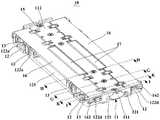
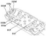
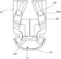
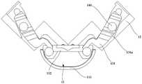
为方便理解本申请实施例提供的转轴机构10,下面结合附图对其结构进行详细的说明。如图8、图9所示,为本申请实施例提供的一种转轴机构10的结构,该结构包括:主轴11、成对布置的转动组件12、以及设置在主轴11两侧的一对支撑板16。每对转动组件12沿垂直于主轴11的轴线方向分设于主轴11的两侧,每个转动组件12包括一个或多个摆臂121,每个摆臂121与主轴11的内壁之间销轴连接。一对支撑板16设置在主轴11两侧,位于主轴11同一侧的支撑板16与转动组件12对应设置。其中,每个支撑板16的一端与主轴11转动连接,相对另一端与转动组件12滑动连接并可相对转动。或者,每个支撑板16的一端与主轴11滑动连接并可相对转动,相对另一端与转动组件12转动连接。结合图10、图11,在位于主轴11两侧的转动组件12相对转动至第一位置时,转动组件12带动对应的支撑板16转动至第二位置,位于主轴11两侧的支撑板16与主轴11之间形成容纳空间。In order to facilitate understanding of the
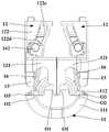
其中,第一位置是指在转轴机构完全折叠状态时转动组件12所在位置,此时,主轴11两侧的转动组件12相互靠近,两侧的转动组件12上与移动终端壳体固定的固定面大致平行,图11里为左侧转动组件12的左侧面与右侧转动组件12的右侧面大致平行。第二位置是指在转轴机构完全折叠状态时支撑板16所在位置,此时,主轴11两侧的支撑板16相互靠近,两侧的支撑板16在靠近主轴11位置的间距比较宽,在远离主轴11位置的间距比较窄。Wherein, the first position refers to the position of the rotating
本申请实施例提供的转轴机构,参阅图8,在主轴11的两侧均布置有转动组件12与支撑板16,转动组件12的摆臂121与主轴11的内壁之间销轴连接。支撑板16连接于主轴11和转动组件12之间,这样在转动组件12相对主轴11转动时,转动组件12将会带动支撑板16相对主轴11转动。其中,在主轴11两侧的转动组件12转动至第一位置时,转动组件12将会带动两侧的支撑板16转动至第二位置,结合图7、图11,两侧的支撑板16在靠近主轴11位置的间距比较宽,在远离主轴11位置的间距比较窄,两侧支撑板16之间上部间距小而下部间距大,形成一个内凹的容纳空间,以容纳柔性屏40部分区域。结合图8,在主轴11两侧的转动组件12转动展开时,转动组件12带动对应的支撑板16转动展开,支撑板16可支撑在转动组件12上,主轴11与支撑板16可共同支撑柔性屏部分区域,支撑效果好。The rotating shaft mechanism provided by the embodiment of the present application, referring to FIG. 8 , has a rotating
将上述转轴机构10应用到可折叠移动终端上,也就是将转轴机构10连接两个壳体之间,位于主轴11同一侧的转动组件12固定到对应的壳体上。结合图7,移动终端由展开状态至折叠状态的过程中,柔性屏40的中间区域42逐渐弯曲且截面形成水滴状,由于主轴11两侧的支撑板16与主轴11之间形成的容纳空间可容纳该柔性屏40的水滴状区域,这样就不会挤压柔性屏40且不起拱。反之,在折叠状态至展开状态的过程中,也不会拉扯到柔性屏40。在折叠与展开的过程中,柔性屏40也不会相对壳体滑动,降低了柔性屏40失效的风险,提高了柔性屏40的可靠性。相比于图2所示现有移动终端,采用图8所示转轴机构10的移动终端,主轴11两侧的转动组件12的摆臂121与主轴11的内壁之间销轴连接,采用双轴的方式实现两个壳体的连接,结合图5,移动终端在折叠状态时的厚度差异较小,两个壳体之间无较大的间隙,降低细长条物体掉入间隙而造成柔性屏损伤的可能性。The above-mentioned
将上述转轴机构10应用到可折叠移动终端上,如图8所示,成对的转动组件12的摆臂121与主轴11的内壁之间销轴连接,位于主轴11同一侧的转动组件12固定于对应的壳体上,采用双轴的方式实现两个壳体的连接,两个壳体可实现折叠与展开动作。参阅图5,移动终端处于完全折叠状态时,从外部看该移动终端,只看到两个壳体之间连接有主轴11,而看不到两个壳体的连接位置存在缺口。相比于现有移动终端两个壳体之间采用单轴的连接方式,本申请实施例提供的转轴机构10采用双轴连接,单个转动组件12相对主轴11的转角可以更小,这样单个转动组件12与主轴11之间连接位置的结构体积可以更小,移动终端在完全展开状态时,转轴机构10并不会过多突出壳体。Apply the above-mentioned
在具体设置主轴时,该主轴可以采用不同的结构,比如是一体结构或分体结构。参阅图12,本申请实施例提供的主轴11包括主外轴111以及主内轴112,主内轴112与主外轴111之间固定连接。作为一种示例,主外轴111的形状可以是半圆形的柱面结构,主内轴112可以是平面结构,主内轴112安装在主外轴111的开口处,主外轴111与主内轴112围成可容置一些零件的容置腔。主内轴112与主外轴111之间可以通过紧固部件(例如,螺钉15)可拆卸的固定连接。当然除了图12所示的连接方式外,还可以采用卡扣或者铆钉将主内轴112与主外轴111固定连接。When specifically setting the main shaft, the main shaft can adopt different structures, such as an integral structure or a split structure. Referring to FIG. 12 , the
在具体布置主轴与转动组件时,参阅图8、图9,主轴11的两端部分别设有一对转动组件12,转动组件12作为转轴机构10的主动部件。将转轴机构10安装于移动终端的两个壳体之间时,位于主轴11沿垂直于其轴线方向同侧的转动组件12与同侧的壳体固定连接,这样在壳体相对主轴11转动时,与该壳体同侧的转动组件12将会相对主轴11同步转动,而且转动过程比较平稳。When specifically arranging the main shaft and the rotating assembly, referring to FIG. 8 and FIG. 9 , a pair of
在具体布置主轴与支撑板时,参阅图8,主轴11沿垂直于其轴线方向的两侧分别设有一个支撑板16,两个支撑板16可跟随主轴11两侧的转动组件12相对主轴11转动。可以理解的是,主轴11的任一侧还可以设置两个以上的支撑板16,将支撑板16连接在主轴11和转动组件12之间,使得转动组件12相对主轴11转动时多个支撑板16跟随转动。When specifically arranging the main shaft and the support plate, refer to FIG. 8 , the
在一些实施例中,为了在两侧支撑板相互靠近时与主轴围成的容纳空间更大,参阅图11,主轴11的两侧均布置有转动组件12与支撑板16,转动组件12的摆臂121转动所绕的轴线O1有两根,支撑板16相对主轴11的转动轴线O3有两根,将支撑板16相对主轴11的转动轴线O3设置在摆臂121转动所绕的轴线O1的两侧。也就是说,摆臂121转动所绕的轴线O1在中部位置,支撑板16相对主轴11的转动轴线O3在两边外侧位置。在主轴11两侧的转动组件12转动至第一位置时,转动组件12将会带动两侧的支撑板16转动至第二位置,两侧的支撑板16在靠近主轴11位置的间距比较宽,在远离主轴11位置的间距比较窄,两侧支撑板16之间上部间距小而下部间距大,形成一个体积更大的内凹的容纳空间,以便于容纳柔性屏的水滴状区域。In some embodiments, in order to have a larger accommodation space surrounded by the main shaft when the support plates on both sides are close to each other, referring to FIG. There are two axes O1 around which the
在实现摆臂121与主轴11内壁之间销轴连接时可以有多种可选实现方式。第一种可选实现方式是:参阅图13、图14,摆臂121上设有连接孔121a,主轴11的内壁上设有转动圆轴111c,转动圆轴111c枢接于连接孔121a。在主轴11包括主外轴与主内轴时,转动圆轴可设置在主外轴或主内轴上。通过使转动圆轴111c枢接于连接孔121a的方式,可实现摆臂121与主轴11之间可靠稳定的转动连接。There are many optional ways to realize the pin-shaft connection between the
示例性的,转动圆轴111c设置于主轴11的轴线方向的端部内壁,摆臂121靠近主轴11的端部设置。将销轴连接的结构设置在主轴11端部,占用主轴11的内部空间较小,使得主轴11内部空间较大,可容置更多的零件。无需如现有移动终端在连接两个壳体之间的转轴壳外表面设置避让孔,无需在转轴壳的外表面覆盖柔性遮蔽件以遮蔽转轴壳的避让孔,并且无需设置使柔性遮蔽件随动的其它机构。本实施例的转轴机构中的主轴11具有完整的外观,摆臂121与主轴11的端部内壁之间销轴连接,结构简单,成本较低。Exemplarily, the rotating
实现摆臂121与主轴11内壁之间销轴连接的第二种可选实现方式是:摆臂121上设有转动圆轴,主轴11的内壁上设有连接孔,转动圆轴枢接于连接孔。在主轴11包括主外轴与主内轴时,连接孔可设置在主外轴或主内轴上。通过使转动圆轴枢接于连接孔的方式,可实现摆臂121与主轴11之间可靠稳定的转动连接。The second optional way to realize the pin connection between the
示例性的,连接孔设置于主轴的轴线方向的端部内壁,摆臂靠近主轴的端部设置。类似于上述转动圆轴111c设置于主轴11的轴线方向的端部的实施例,本实施例中将连接孔设置于主轴的轴线方向的端部,该销轴连接的结构占用主轴11的内部空间较小,主轴11具有完整的外观,结构简单。Exemplarily, the connection hole is disposed on the inner wall of the end of the main shaft in the axial direction, and the swing arm is disposed near the end of the main shaft. Similar to the above-mentioned embodiment in which the rotating
对于上述两种实现摆臂121与主轴11内壁之间销轴连接的可选实现方式,为了使移动终端在完全折叠状态时的厚度差异小,使转动圆轴的轴线与主轴11的轴线平行,位于主轴11两侧的转动组件12相对主轴11转动至第一位置后,两侧的转动组件12相互靠近,结合图11,两侧的转动组件12上与移动终端壳体固定的固定面相互平行,图11里为左侧转动组件12的左侧面与右侧转动组件12的右侧面平行,使得移动终端在完全折叠状态时的厚度差异小,实现等厚效果。For the above two optional implementation methods for realizing the pin-shaft connection between the
在一些实施例中,为了使摆臂121与主轴11的转动连接更稳定可靠,提高摆臂121与主轴11之间连接位置的结构强度,还可以在摆臂121与主轴11之间设置以下辅助性转动连接方式。第一种可选实现方式是:参阅图13、图14,主轴11上设有与摆臂121对应的圆弧槽111d,结合图15,摆臂121上设有滑动装配在圆弧槽111d的圆弧臂121b;圆弧臂121b的轴线与摆臂121转动所绕的轴线重合。通过使圆弧臂121b与圆弧槽111d滑动连接,圆弧臂121b的轴线与摆臂121轴线同轴,提升摆臂121与主轴11之间转动连接的可靠性。In some embodiments, in order to make the rotational connection between the
其中,在主轴11包括主外轴和主内轴时,圆弧槽111d可设置在主外轴111的端部内壁上;或,圆弧槽可设置在主内轴和主外轴上。将摆臂121上的圆弧臂121b与主轴11的圆弧槽111d连接,再将主外轴和主内轴装配好,圆弧臂121b滑动装配在圆弧槽111d内,使摆臂121与主轴11转动连接更平稳。Wherein, when the
为了使摆臂121与主轴11的连接更稳定,摆臂121上可设置多个同心的圆弧臂121b,主轴11设置多个同心的圆弧槽111d,圆弧臂121b与圆弧槽111d对应设置,这样有利于摆臂121与主轴11之间可靠地转动连接。In order to make the connection between the
实现摆臂121与主轴11辅助性转动连接的第二种可选实现方式是:参阅图16,主轴11上设有与摆臂121对应的弧形槽112b,结合图15,摆臂121上设有滑动装配在弧形槽112b的导向柱121c;弧形槽112b的轴线与摆臂121转动所绕的轴线重合。通过使导向柱121c与弧形槽112b滑动连接,弧形槽112b轴线与摆臂121轴线同轴,提升摆臂121与主轴11之间转动连接的可靠性。The second optional way to realize the auxiliary rotational connection between the
其中,在主轴11包括主外轴和主内轴时,弧形槽112b可设置在主内轴上。将摆臂121上的导向柱121c与主轴11的弧形槽112b连接,再将主外轴和主内轴装配好,导向柱121c滑动装配在弧形槽112b内,使摆臂121与主轴11转动连接更平稳。Wherein, when the
应理解,可选用上述两种实现方式中的一种或两种,这样有利于转动组件12与主轴11更稳定地转动连接,而且可以提高结构强度。示例性的,参阅图13,摆臂121与主轴11之间通过连接孔121a与转动圆轴111c实现销轴连接,结合图15,在摆臂121的外内两侧面分别设置圆弧臂121b与导向柱121c,圆弧臂121b与主轴11端部的圆弧槽111d配合,结合图16,导向柱121c与主轴11端部的弧形槽112b配合,这样使得摆臂121可以稳定地相对主轴11转动,而且有效提高结构强度,满足结构紧凑的要求。It should be understood that one or both of the above two implementation manners can be selected, which is conducive to a more stable rotational connection between the rotating
作为本申请的另一个实施例,参阅图8,在实现支撑板16连接于主轴11与转动组件12之间时,可以将支撑板16的一端与主轴11转动连接,支撑板16的相对另一端与转动组件12滑动连接并可相对转动。这样在转动组件12相对主轴11转动时,转动组件12将会带动对应的支撑板16相对主轴11同向转动,实现支撑板16的联动。As another embodiment of the present application, referring to FIG. 8, when the
其中,在实现支撑板与主轴转动连接时有四种可选实现方式。第一种可选实现方式是:参阅图9、图17,支撑板16靠近主轴11的一端设有第一固定销轴161,主轴11设有与第一固定销轴161枢接的第一枢接孔,这样可以将支撑板16与主轴11转动连接。其中,结合图14、图16,第一枢接孔可以是由主内轴112与主外轴111上的各一个半圆柱孔113组成,也可以将圆柱形的第一枢接孔直接设置在主内轴112或主外轴111上。为了提高支撑板16与主轴11连接的可靠性,支撑板16设有多个第一固定销轴161,主轴11对应设有多个第一枢接孔,第一固定销轴161与第一枢接孔对应设置,这样有利于支撑板16稳定地与主轴11转动连接。第二种可选实现方式是:将第一固定销轴与第一枢接孔的位置互换,也就是主轴11设有第一固定销轴,支撑板16靠近主轴11的一端设有与第一固定销轴枢接的第一枢接孔,这样也可以将支撑板16与主轴11转动连接。第三种可选实现方式是:支撑板16靠近主轴11的一端设有第一弧线臂(图中未显示),第一弧线臂的轴线为支撑板16与主轴11之间的转动轴线,主轴11设有与第一弧线臂滑动连接的第一弧线槽(图中未显示)。第四种可选实现方式是:主轴11设有第一弧线臂(图中未显示),第一弧线臂的轴线为支撑板16与主轴11之间的转动轴线,支撑板16靠近主轴11的一端设有与第一弧线臂滑动连接的第一弧线槽(图中未显示)。后两种方式为虚拟轴连接,两个结构件分别设置相配合的弧线臂与弧线槽,实现两个结构件的转动连接,弧线臂与弧线槽的位置互换形成了这两种方式。Among them, there are four optional implementation methods when realizing the rotational connection between the support plate and the main shaft. The first optional implementation is: referring to Fig. 9 and Fig. 17, the end of the
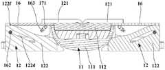
其中,在实现支撑板16与转动组件12滑动连接并可相对转动时,参阅图8、图9,支撑板16的远离主轴11的一端设有第一滑动销轴162,转动组件12设有第一滑槽122d,第一滑动销轴162滑动装配在第一滑槽122d。结合图18至图20,在转动组件12相对主轴11转动时,第一滑动销轴162与第一滑槽122d滑动连接,转动组件12将会带动支撑板16相对主轴11转动。参阅图9,支撑板16上设置安装孔162a以安装第一滑动销轴162,这样便于支撑板16与第一滑动销轴162的成型与装配,降低制作难度。其中,第一滑槽122d的延伸路径可以呈直线、弧线或其它形状。示例性的,参阅图18至图20,转动组件12包括支撑座122及连接于支撑座122的摆臂121,第一滑槽122d的延伸路径是直线的,在转动组件12相对主轴11转动的径向且朝向轴心的方向上,第一滑槽122d的延伸路径朝向支撑座122的底面倾斜。支撑座122的底面是指支撑座122与移动终端壳体固定的一面。第一滑槽122d设置为由外侧到内侧朝向支撑座122的底面倾斜延伸,结合图20,在主轴11两侧的转动组件12完全折叠后,主轴11两侧的支撑板16将会围合形成一个下部宽而上部窄的容纳空间,便于容纳柔性屏的水滴状区域。Wherein, when the supporting
在一些实施例中,参阅图15,转动组件12的支撑座122的顶面包括配合面122e、展开定位面122f与折叠定位面122g,配合面122e与第一滑槽122d的延伸路径平行,展开定位面122f与折叠定位面122g分别连接于配合面122e的两侧,展开定位面122f可以与支撑座122的底面平行。参阅图18,在主轴11两侧的转动组件12完全展开时,支撑板16的底面抵设于支撑座122的展开定位面122f,使得支撑板16与主轴11的上表面维持在同一表面上,可靠地支撑柔性屏展开后的中间区域。结合图19,在转动组件12相对主轴11转动的过程中,第一滑动销轴162与第一滑槽122d滑动连接,支撑板16的底面滑动抵设于支撑座122的配合面122e,配合引导支撑板16按预定路径移动。参阅图20,在两侧的转动组件12完全折叠后,支撑板16的底面抵设于支撑座122的折叠定位面122g上,使得位于主轴11两侧的支撑板16之间的距离比较大以更好地容纳柔性屏的水滴状区域。In some embodiments, referring to FIG. 15 , the top surface of the
在一些实施例中,在具体设置支撑板与主轴时,参阅图17,将支撑板16相对主轴11的转动轴线O3靠近主轴11在宽度方向的边缘设置,宽度方向在图17里是左右方向,这样便于将支撑板16与主轴11转动连接。结合图20,在主轴11两侧的支撑板16转动至第二位置时,位于主轴11两侧的支撑板16与主轴11之间将会形成更大的容纳空间以容纳柔性屏的水滴状区域。参阅图8,转轴机构10在完全展开时,支撑板16可以与主轴11的上表面处于一个平面上,以更好地支撑柔性屏完全展开的中间区域。In some embodiments, when specifically setting the support plate and the main shaft, refer to FIG. 17 , and set the
在实现支撑板16与转动组件12滑动连接并可相对转动时,第一滑动销轴与第一滑槽的位置可互换,也就是转动组件12设有第一滑动销轴,支撑板16的远离主轴11的一端设有与第一滑动销轴滑动连接的第一滑槽,这样也可以实现支撑板16与转动组件12滑动连接并可相对转动,进而使转动组件12带动支撑板16相对主轴11转动。When the supporting
作为本申请的另一个实施例,在实现支撑板16连接在主轴11与转动组件12之间时,可以将支撑板16的一端与主轴11滑动连接并可相对转动,支撑板16的相对另一端与转动组件12转动连接。这样在转动组件12相对主轴11转动时,转动组件12将会带动对应的支撑板16相对主轴11同向转动,实现支撑板16的联动。As another embodiment of the present application, when the
其中,在实现支撑板16与主轴11滑动连接并可相对转动时,支撑板16靠近主轴11的一端设有第二滑动销轴(图中未显示),主轴11设有第二滑槽(图中未显示),第二滑动销轴滑动装配在第二滑槽。在转动组件12相对主轴11转动时,第二滑动销轴与第二滑槽滑动连接,转动组件12将会带动支撑板16相对主轴11转动与滑动。除此之外,主轴11设有第二滑动销轴(图中未显示),支撑板16靠近主轴11的一端设有与第二滑动销轴滑动连接的第二滑槽(图中未显示),这样也可实现支撑板16与主轴11滑动连接并可相对转动,进而使转动组件12带动支撑板16相对主轴11转动与滑动。Wherein, when the
其中,在实现支撑板16与转动组件12转动连接时有四种可选实现方式。第一种可选实现方式是:转动组件12设有第二固定销轴(图中未显示),支撑板16的远离主轴11的一端设有与第二固定销轴枢接的第二枢接孔(图中未显示)。第二种可选实现方式是:支撑板16的远离主轴11的一端设有第二固定销轴(图中未显示),转动组件12设有与第二固定销轴枢接的第二枢接孔(图中未显示)。第三种可选实现方式是:转动组件12设有第二弧线臂(图中未显示),第二弧线臂的轴线为支撑板16与转动组件12之间的转动轴线,支撑板16的远离主轴11的一端设有与第二弧线臂滑动连接的第二弧线槽(图中未显示)。第四种可选实现方式是:支撑板16的远离主轴11的一端设有第二弧线臂(图中未显示),第二弧线臂的轴线为支撑板16与转动组件12之间的转动轴线,转动组件12设有与第二弧线臂滑动连接的第二弧线槽(图中未显示)。前两种方式为销轴连接,两个结构件分别设置相配合的固定销轴与枢接孔,实现两个结构件的转动连接,固定销轴与枢接孔的位置互换形成了这两种方式。后两种方式为虚拟轴连接,两个结构件分别设置相配合的弧线臂与弧线槽,实现两个结构件的转动连接,弧线臂与弧线槽的位置互换形成了这两种方式。Wherein, there are four optional realization ways when realizing the rotational connection between the
作为本申请的另一个实施例,参阅图8,主轴11内部会经过用于连接两侧壳体内部元器件的排线(图中未显示),为了保护经过主轴11内的排线,在主轴11与支撑板16之间设置保护板17,保护板17沿垂直于主轴11的轴线方向分设于主轴11的两侧,排线设置在保护板17的底面以降低排线弯折损坏的可能性。结合图21,在设置保护板17时,位于主轴11同侧的保护板17与支撑板16对应设置。保护板17具有第一端及与该第一端相对的第二端,第一端与主轴11转动连接,第二端与保护板17对应的支撑板16滑动连接。保护板17相对主轴11的转动轴线与支撑板16相对主轴11的转动轴线相靠近,比如两者平行间隔设置。在转动组件12相对主轴11转动的过程中,转动组件12带动支撑板16相对主轴11转动,而支撑板16带动保护板17相对主轴11转动。结合图7,在主轴11两侧的转动组件12转动且相互靠近的过程中,主轴11两侧的支撑板16将会相对主轴11转动并相互靠近,支撑板16会带动保护板17转动,保护板17并不会影响容纳空间内的柔性屏40的中间区域42。参阅图8,在主轴11两侧的支撑板16完全展开时,支撑板16、保护板17与主轴11的上表面平齐,共同支撑柔性屏完全展开后的中间区域。As another embodiment of the present application, referring to Fig. 8, the interior of the
在实现保护板17与主轴11转动连接时,参阅图9,主轴11的一端设有第三固定销轴114,保护板17靠近主轴11的一端设有与第三固定销轴114枢接的第三枢接孔172,这样可以将保护板17与主轴11转动连接。为了提高保护板17与主轴11连接的可靠性,保护板17设有多个第三枢接孔172,主轴11对应设有多个第三固定销轴,第三固定销轴与第三枢接孔对应设置,这样有利于保护板17稳定地与主轴11转动连接。此外,第三固定销轴与第三枢接孔的位置可互换,也就是保护板17靠近主轴11的一端设有第三固定销轴,主轴11设有与第三固定销轴枢接的第三枢接孔,这样也可以将保护板17与主轴11转动连接。When the
在实现保护板17与支撑板16滑动连接时,参阅图9、图21,保护板17靠近支撑板16的一端设有第三滑动销轴171,支撑板16设有第三滑槽163,第三滑动销轴171滑动装配在第三滑槽163。在支撑板16相对主轴11转动时,第三滑动销轴171与第三滑槽163滑动连接,支撑板16将会带动保护板17相对主轴11转动。其中,第三滑槽163的延伸路径可以呈直线、弧线或其它形状。示例性的,参阅图18,第三滑槽163的延伸路径是直线的,在支撑板16相对主轴11转动的径向且朝向轴心的方向上,第三滑槽163的延伸路径朝向支撑板16的顶面倾斜。支撑板16的顶面是指支撑板16与用于支撑柔性屏的一面。第三滑槽163设置为由外侧到内侧朝向支撑板16的顶面倾斜延伸,结合图20,在主轴11两侧的转动组件12完全折叠后,两侧的支撑板16相互靠拢,主轴11两侧的支撑板16与保护板17跟主轴11围合形成一个由上到下逐渐变宽又逐渐变窄的容纳空间,便于容纳柔性屏的水滴状区域。此外,第三滑动销轴与第三滑槽的位置可互换,也就是支撑板16设有第三滑动销轴,保护板17靠近支撑板16的一端设有与第三滑动销轴滑动连接的第三滑槽,这样也可以将保护板17与支撑板16转动连接,进而使支撑板16带动保护板17相对主轴11转动。When realizing the sliding connection between the
在一些实施例中,为了使支撑板与保护板的支撑面积尽量大以提升对柔性屏的支撑效果,参阅图9,保护板17可以制作得比主轴11与支撑板16更短,只要能保护到排线即可。主轴11的主内轴112开设有用于避让保护板17的第一缺口112c。支撑板16开设有第二缺口164,第二缺口164用于避让与支撑板16对应的保护板17。结合图8,在转动组件12转动展开时,支撑板16与保护板17将会展开,保护板17嵌设在第一缺口112c与第二缺口164内,支撑板16、保护板17与主轴11的排布会更紧密,共同支撑柔性屏的中间区域,支撑效果更好。In some embodiments, in order to make the support area of the support plate and the protection plate as large as possible to improve the support effect on the flexible screen, referring to FIG. 9, the
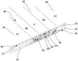
作为本申请的另一个实施例,参阅图13、图22,转轴机构10还包括成对布置的阻尼组,每对阻尼组沿垂直于主轴11的轴线方向分设于主轴11的两侧,阻尼组包括位移组件13与限位组件14,位移组件13与主轴11转动连接且与转动组件12滑动连接。限位组件14设于转动组件12与位移组件13之间,在位移组件13相对主轴11转动时,限位组件14用于为位移组件13提供阻尼作用。位移组件13的作用是产生与转动组件12不同的转动相位差,也就是转动组件12转动带动位移组件13转动时,转动组件12与位移组件13的转角是不同的,这样就可以使位移组件13产生相对转动组件12的滑动位移。转动组件12中的摆臂121转动所绕的轴线与位移组件13相对主轴11的转动轴线间隔设置,而且转动组件12的转动轴线与主轴11中轴线的间距小于位移组件13的转动轴线与主轴11中轴线的间距。在转动组件12相对主轴11转动时,位移组件13跟随转动组件12相对主轴11转动,并且位移组件13相对转动组件12有滑动位移,限位组件14将会对位移组件13提供阻尼作用,从而将位移组件13限定在某个转动位,位移组件13与转动组件12转动连接,转动组件12跟随位移组件13被限定在某个转动位。将转轴机构10安装于移动终端的两个壳体之间时,转动组件12被限定在某个转动位,壳体也被限定在某个位置。As another embodiment of the present application, referring to Fig. 13 and Fig. 22, the
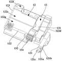
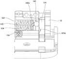
在具体设置转动组件与阻尼组时,参阅图12、图13,转动组件12包括支撑座122及连接于支撑座122的摆臂121,结合图22,支撑座122开设有第一容置槽122a及第二容置槽122b。第一容置槽122a的延伸方向与第二容置槽122b的延伸方向可以垂直,而第一容置槽122a的延伸方向与主轴11的轴线也可以垂直。第一容置槽122a的延伸方向是指其长度方向。第二容置槽122b的延伸方向是指其长度方向。阻尼组包括位移组件13与限位组件14。位移组件13容置于第一容置槽122a,限位组件14容置于第二容置槽122b。When setting up the rotating assembly and the damping group, refer to Figure 12 and Figure 13, the rotating
参阅图22,位移组件13包括连杆部131,连杆部131滑动安装于第一容置槽122a而不会脱离第一容置槽122a,结合图12、图23,连杆部131的第一端转动安装于主轴11。参阅图22、图24,限位组件14包括弹性结构件142和设于弹性结构件142一端的阻尼件141,阻尼件141可沿连杆部131靠近第二容置槽122b的侧壁移动,阻尼件141用于为位移组件13提供阻尼作用,弹性结构件142可沿第二容置槽122b的延伸方向伸缩。结合图11,在转动组件12相对主轴11转动时,转动组件12中的摆臂121转动所绕的轴线O1与位移组件13中的连杆部相对主轴11的转动轴线O2间隔设置,结合图12、图24,连杆部131会跟随转动组件12相对主轴11转动,并且连杆部131会沿第一容置槽122a的延伸方向移动。在连杆部131相对支撑座122滑动过程中,在弹性结构件142的作用下,阻尼件141抵设于连杆部131的一侧壁上,阻尼件141对连杆部131产生一定的摩擦力,该摩擦力需要大于预定阈值,才会使得位移组件13可限定在相对主轴11的某个转动位,从而对位移组件13提供阻尼作用。而连杆部131保持滑动安装于第一容置槽122a,从而使转动组件12相对主轴11维持在某个转动位。Referring to FIG. 22 , the
在一些实施例中,为了使转动组件更稳定可靠地维持在预定位置上,参阅图22,连杆部131靠近阻尼件141的侧壁设置有限位凹槽131a。在转动组件12相对主轴11转动时,连杆部131沿第一容置槽122a的延伸方向移动。在弹性结构件142的作用下,阻尼件141可沿连杆部131靠近第二容置槽122b的侧壁移动。由于连杆部131靠近第二容置槽122b的侧壁具有限位凹槽131a,这样阻尼件141在移动的过程中会在弹性结构件142的弹力作用下落入限位凹槽131a,以阻止阻尼件141继续在连杆部131上运动,从而使转动组件12停止转动,进而可使移动终端的壳体可靠地维持在对应的转动位。其中,连杆部131上的限位凹槽131a的数量可以为一个或多个,在连杆部131具有多个限位凹槽131a时,配合阻尼件141与弹性结构件142,可实现转动组件12在多个位置的可靠限位。其中,阻尼件141可以为滚珠或滑动体。阻尼件141为滚珠时,滚珠可沿连杆部131靠近第二容置槽122b的侧壁滚动,移动更灵活。阻尼件141为滑动体时,滑动体可沿连杆部131靠近第二容置槽122b的侧壁滑动,提供更好的阻尼力。滑动体可以设置与限位凹槽131a相适配的限位凸面,在滑动体移动至限位凹槽131a处,限位凸面将会滑入限位凹槽131a,相比于阻尼件采用滚珠的方式,阻尼件采用具有限位凸面的滑动体的方式可提供更大的阻尼力。In some embodiments, in order to maintain the rotating assembly at a predetermined position more stably and reliably, referring to FIG. 22 , a limiting
为了对可折叠移动终端的折叠状态改变以及维持做更好的说明,参阅图8、图23和图24,移动终端的两个壳体之间的夹角为180°,参阅图23,此时,阻尼件141落在限位凹槽131a中。当需要将移动终端的两个壳体之间的夹角从180°变为0°时,转动组件12绕主轴11转动,连杆部131随之转动,阻尼件141沿连杆部131的侧壁移动。参阅图25和图26,当阻尼件141落入限位凹槽131a中时,限位凹槽131a的槽壁阻止阻尼件141继续在连杆部131上运动,从而使转动组件12停止转动,进而使移动终端的两个壳体维持于0°夹角的状态。由于连杆部131靠近第二容置槽122b的侧壁具有多个限位凹槽131a,这样可通过使阻尼件141落入对应的限位凹槽131a中来实现转动组件12对应转动位的维持,例如,可通过合理设置使移动终端的两个壳体之间的夹角维持在90°。并且,在本申请实施方式中,参阅图27和图29,当阻尼件141在相邻两个限位凹槽131a之间运动时,会使其与连杆部131之间产生恒定的摩擦力,从而可实现转动组件12与连杆部131之间具有恒定的阻尼,此时可使手感恒定。另外,值得一提的是,参阅图23和图25,当连杆部131只在与移动终端的两个壳体之间的夹角为0°和180°相对应的位置设置有限位凹槽131a时,结合图25和图27,用户在折叠该移动终端时,只需手动使两个壳体之间具有较小的夹角(例如30°),就可以使阻尼件141在弹性结构件142的作用下进入0°对应的限位凹槽131a,以实现两个壳体的自合;同样的,用户在展开该移动终端时,只需手动使两个壳体之间具有较大的夹角(例如150°),就可以使阻尼件141在弹性结构件142的作用下进入180°对应的限位凹槽131a,以实现两个壳体的自开。由此可见,采用本技术方案的转轴机构10,可以实现可折叠移动终端的自开合,从而有利于提升用户体验。In order to better explain the change and maintenance of the folding state of the foldable mobile terminal, refer to Figure 8, Figure 23 and Figure 24, the angle between the two shells of the mobile terminal is 180°, refer to Figure 23, at this time , the damping
在具体设置第一容置槽122a与位移组件13时,参阅图9、图22,第一容置槽122a的槽壁开设有导向槽122c,导向槽122c的延伸方向与第一容置槽122a的延伸方向相同,其中,导向槽122c的设置位置可以有多种,在图9、图22所示的实施方式中,导向槽122c设置在第一容置槽122a远离第二容置槽122b的槽壁上。结合图22,位移组件13还包括设置于连杆部131上且滑动装配在导向槽122c的滑动部133。其中,滑动部133可以但不限于为设置于连杆部131靠近导向槽122c一侧的圆柱形凸起。在位移组件13的连杆部131随转动组件12转动的过程中,滑动部133限位于导向槽122c,且可沿导向槽122c滑动,这样在转动组件12转动的过程中,可避免位移组件13脱离转动组件12,从而有效的提高位移组件13运动的可靠性。当然为了实现上述目的,还可以采用在第一容置槽122a中设置挡片等方式。When specifically setting the
为了实现连杆部131与主轴11的转动连接,参阅图14,可以采用在主外轴111上设置第三容置槽111a的方案。具体的,主外轴111上设置有第三容置槽111a,结合图12,主内轴112设置有用于露出第三容置槽111a的开口112a;结合图13,连杆部131的第一端容置于第三容置槽111a,且与主轴11转动连接。连杆部131的第一端设置有支撑轴132,第三容置槽111a包括可容置该支撑轴132的圆弧面111b。采用该结构时,需要先将连杆部131的支撑轴132放置于第三容置槽111a的圆弧面111b上,然后将主内轴112盖设于主外轴111上并加以紧固,从而可使支撑轴132卡设于第三容置槽111a,并可沿圆弧面111b转动。结合图8,在主轴11两侧的转动组件12完全展开时,支撑轴132将会被主内轴112的内壁挡住以限定连杆部131的位置,从而限定位移组件13相对主轴11的转动位置。位移组件13还可通过铰接或者枢装等方式来实现与主轴11的转动连接,结合图12,位移组件13在转动的过程中,主内轴112的开口112a不会对其造成干涉。In order to realize the rotational connection between the connecting
在一些实施例中,在具体设置弹性结构件时,在图22、图24所示的实施例中,转动组件12与阻尼组中的位移组件13、限位组件14为一一对应的设置关系。转动组件12还包括设置于第二容置槽122b远离位移组件13一端的挡板123,弹性结构件142的一端固定于该挡板123。其中,弹性结构件142可以但不限于为弹簧,当弹性结构件142为弹簧时,为了实现对弹簧的限位,以使其在运动过程中不发生弯折,可以在挡板123上设置限位支柱124,从而使弹簧套设于限位支柱124,其中,弹簧可以为一条,也可以为多条,这样可以通过改变弹簧的数量来改变位移组件13与转动组件12之间的阻尼力的大小,除此之外,还可以通过改变弹簧的刚性来改变阻尼力的大小。在该弹簧靠近位移组件13的一端还设置有连接板142a,连接板142a卡接于第二容置槽122b的槽壁,以使弹簧能够限位于第二容置槽122b。连接板142a上也可以设置限位支柱124,并使弹簧套设于该限位支柱124。此时,阻尼件141与连接板142a相抵接,并可沿连接板142a的表面运动,这样可减小弹性结构件142与阻尼件141之间的摩擦,使阻尼件141的运动更加灵活。In some embodiments, when specifically setting up the elastic structural members, in the embodiments shown in Fig. 22 and Fig. 24, the rotating
为了改变位移组件13与转动组件12之间的阻尼力的大小还可以通过改变阻尼件141的数量来实现,具体的,在图9所示的实施例中,一个转动组件12设置有两个位移组件13,两个位移组件13共用一个限位组件(图中未显示),转动组件12、限位组件以及主轴11的设置方式稍有不同。其中,转动组件12设置有两个用于容置位移组件13的第一容置槽122a,主轴11上的第三容置槽111a与第一容置槽122a一一对应设置,以使位移组件13能够一一对应的容置于第一容置槽122a以及第三容置槽111a。此时,在具体设置弹性结构件142时,可参阅图24,不同的是使弹性结构件142的两端各设置一个阻尼件141,并使阻尼件141能够沿对应的位移组件13的连杆部131侧壁移动。可以理解的是,在该实施方式中,两个连杆部131相对设置的侧壁上均设置有多个一一对应的限位凹槽131a。弹性结构件142的具体设置方式可参阅上一实施例,由弹簧或弹簧组,以及设置于弹簧(或弹簧组)端部的连接板142a组成,阻尼件141与对应侧的连接板142a相抵接。其中,为避免弹簧(或弹簧组)在运动的过程中发生弯折,可在连接板142a上设置限位支柱,并使弹簧套设于对应的限位支柱即可。采用该种设置方式可以有效的增加限位组件14与连杆部131之间的阻尼力,从而实现包含有该转动组件12的可折叠移动终端的折叠状态的有效维持。另外,参阅图9、图10,位于主轴11同一侧的转动组件12之间可通过加强杆125连接,这样可以提高结构强度。In order to change the damping force between the
作为本申请的另一个实施例,为了使移动终端的两侧壳体可以同步折叠,就是同时收拢或展开的效果,参阅图13、图29,在连杆部131的第一端处固定设置齿轮部134,连杆部131与主轴11之间的转动轴线O2与齿轮部134的轴线重合;主轴11设有成对布置且相啮合的同步齿轮18,成对的同步齿轮18与成对的阻尼组对应设置,同一对阻尼组中的位移组件13的齿轮部134与成对的同步齿轮18一一对应地啮合。在其中一个转动组件12相对主轴11转动时,该转动组件12上的位移组件13相对主轴11转动并相对转动组件12滑动,转动组件12上的齿轮部134与其中一个同步齿轮18啮合,另一个同步齿轮18啮合转动,同一对阻尼组中的位移组件13与转动组件12对称布置,从而使另一侧的位移组件13与转动组件12跟随运动,即另一侧的转动组件12也跟随折叠或展开,进而实现移动终端的同步折叠。其中,参阅图12,同一对阻尼组的位移组件13中的齿轮部134与成对的同步齿轮18位于同一平面位置。结合图29,将齿轮部134相对主轴11的转动轴线O2靠近主轴11在宽度方向的边缘设置,宽度方向在图29里是左右方向,这样同步齿轮18可设置在主轴11的内部,充分利用主轴11宽度方向的空间,使得主轴11宽度尺寸较小。参阅图9,在一个转动组件12设置有两个位移组件13时,两个位移组件13均可配置齿轮部134,主轴11也配置更多对同步齿轮18,齿轮部134与同步齿轮18啮合传动,这样可使主轴11两侧的位移组件13相对主轴11的转动更顺畅,进而使主轴11两侧的转动组件12相对主轴11转动更稳定可靠。As another embodiment of the present application, in order to make the two sides of the mobile terminal can be folded synchronously, that is, the effect of being folded or unfolded at the same time, referring to Fig. 13 and Fig. 29, a gear is fixedly arranged at the first end of the connecting
参阅图3、图4,本申请实施例提供一种可折叠移动终端,包括上述任一种转轴机构10、第一壳体20、第二壳体30以及柔性屏40,第一壳体20与第二壳体30分设于转轴机构10的两侧,结合图8,位于主轴11其中一侧的转动组件12固定于第一壳体20,位于主轴11另外一侧的转动组件12固定于第二壳体30,柔性屏40的两端部41分别固定于第一壳体20与第二壳体30,柔性屏40的中间区域42对应主轴11与支撑板16设置。Referring to Fig. 3 and Fig. 4, an embodiment of the present application provides a foldable mobile terminal, including any of the above-mentioned
本申请实施例提供的可折叠移动终端,将上述转轴机构10应用到该可折叠移动终端,主轴11两侧的转动组件12分别固定到第一壳体20与第二壳体30,实现第一壳体20与第二壳体30的连接,并且柔性屏40的两端部41分别固定于第一壳体20与第二壳体30。参阅图8,在主轴11的两侧均布置有转动组件12与支撑板16,转动组件12的摆臂121与主轴11内壁之间销轴连接。支撑板16连接于主轴11和转动组件12之间,这样在转动组件12相对主轴11转动时,转动组件12将会带动支撑板16相对主轴11转动。其中,在主轴11两侧的转动组件12转动至第一位置时,转动组件12将会带动两侧的支撑板16转动至第二位置,结合图7,两侧的支撑板16在靠近主轴11位置的间距比较宽,在远离主轴11位置的间距比较窄,两侧支撑板16之间上部间距小而下部间距大,形成一个内凹的容纳空间,以容纳柔性屏40部分区域。结合图6,在主轴11两侧的转动组件12转动展开时,转动组件12带动对应的支撑板16转动展开,支撑板16可支撑在转动组件12上,主轴11与支撑板16可共同支撑柔性屏40部分区域,支撑效果好。In the foldable mobile terminal provided by the embodiment of the present application, the above-mentioned
参阅图7,移动终端由展开状态至折叠状态的过程中,柔性屏40的中间区域42逐渐弯曲且截面形成水滴状,由于位于主轴11两侧的支撑板16与主轴11之间形成的容纳空间可容纳该柔性屏40的水滴状区域,这样就不会挤压柔性屏40且不起拱。反之,在折叠状态至展开状态的过程中,也不拉扯到柔性屏40,柔性屏40的中间区域42逐渐展平,参阅图6,主轴11与支撑板16共同支撑柔性屏40展平后的中间区域42。其中,位于主轴11两侧的支撑板16分别支撑柔性屏40的B1和B2区,主轴11支撑C区。在折叠与展开的过程中,柔性屏40也不会相对壳体滑动,降低了柔性屏40失效的风险,提高了柔性屏40的可靠性。结合图8,位于主轴11两侧的转动组件12的摆臂121与主轴11内壁之间销轴连接,采用双轴的方式实现两个壳体的连接,结合图5,移动终端在折叠状态时的厚度差异较小,两个壳体之间无较大的间隙,降低细长条物体掉入间隙而造成柔性屏损伤的可能性。Referring to FIG. 7 , during the process of the mobile terminal from the unfolded state to the folded state, the
参阅图5,可折叠移动终端处于完全折叠状态时,从外部看该移动终端,只看到第一壳体20与第二壳体30之间连接有主轴11,而看不到两个壳体的连接位置存在缺口的情况。相比于现有移动终端两个壳体之间采用单轴的连接方式,本申请实施例提供的转轴机构10采用双轴连接,单个转动组件12相对主轴11的转角可以更小,这样单个转动组件12与主轴11之间连接位置的结构体积可以更小,结合图4,移动终端在完全展开状态时,转轴机构10并不会过多突出壳体。Referring to Fig. 5, when the foldable mobile terminal is in a fully folded state, when the mobile terminal is viewed from the outside, only the
在一些实施例中,为了便于壳体与元器件的装配,参阅图3、图4,将壳体设置为前壳与后壳的方式。其中,第一壳体20包括相连接的第一前壳21与第一后壳22,第二壳体30包括相连接的第二前壳31与第二后壳32。第一壳体20与第二壳体30的结构是类似的,以第一壳体20为例进行说明。第一前壳21与第一后壳22通过粘胶或螺钉锁附连接,第一后壳22在靠近转轴机构10的位置形成有放置槽221,结合图8,放置槽221内可以放置转轴机构10其中一侧的转动组件12与支撑板16,转动组件12可通过粘胶或其它固定方式固定在放置槽221的底面上,而支撑板16与主轴11的上表面大致与第一前壳21的上表面平齐。第二壳体30的情况类似。结合图3,图4,这样第一前壳21的第一面20a、支撑板16、主轴11的上表面与第二前壳31的第一面30a,就可以形成一个支撑柔性屏40的支撑面。将柔性屏40的两个端部分别固定于第一前壳21与第二前壳31,柔性屏40的中间区域42对应主轴11与支撑板16设置。第一后壳22的相对两个长条形侧壁221遮挡主轴11其中一侧转动组件12支撑座122的侧面,第二后壳32的相对两个长条形侧壁321遮挡着主轴11另外一侧转动组件12支撑座122的侧面。In some embodiments, in order to facilitate the assembly of the housing and components, referring to FIG. 3 and FIG. 4 , the housing is arranged in the form of a front housing and a rear housing. Wherein, the
结合图5,在移动终端完全折叠后,从侧面看移动终端,只会看到主轴11的端部、第一壳体20与第二壳体30的侧壁,而看不到转动组件12与支撑板16,而且第一前壳21与第二前壳31相贴近,第一壳体20、第二壳体30与主轴11之间均无较大的镂空间隙。从正面看移动终端,以第一壳体20为例进行说明,第一后壳22具有靠近第二后壳32设置的内端边缘222,参阅图6,在移动终端展开时第一后壳22的内端边缘222靠近主外轴111的外表面设置,参阅图7,在完全折叠后第一后壳22的内端边缘222靠近于主轴11在宽度方向其中一侧的长边11a。当移动终端的两个壳体之间为任意折叠角度时,第一壳体20与主轴11之间的间隙足够小,可实现第一壳体20与主轴11之间间隙的遮蔽。第二壳体30与主轴11的情况是类似的,可实现第二壳体30与主轴11之间间隙的遮蔽。因此,转轴机构10的正面和侧面都没有较大的镂空间隙,满足整机的外观完整。Referring to FIG. 5 , after the mobile terminal is completely folded, looking at the mobile terminal from the side, only the end of the
最后应说明的是:以上所述,仅为本申请的具体实施方式,但本申请的保护范围并不局限于此,任何在本申请揭露的技术范围内的变化或替换,都应涵盖在本申请的保护范围之内。因此,本申请的保护范围应以所述权利要求的保护范围为准。Finally, it should be noted that: the above is only a specific implementation of the application, but the scope of protection of the application is not limited thereto, and any changes or replacements within the technical scope disclosed in the application shall be covered by this application. within the scope of the application. Therefore, the protection scope of the present application should be determined by the protection scope of the claims.
Claims (21)
Priority Applications (2)
| Application Number | Priority Date | Filing Date | Title |
|---|---|---|---|
| CN202010617287.8ACN113873059B (en) | 2020-06-30 | 2020-06-30 | Rotating shaft mechanism and foldable mobile terminal |
| PCT/CN2021/101746WO2022001769A1 (en) | 2020-06-30 | 2021-06-23 | Rotating shaft mechanism and foldable mobile terminal |
Applications Claiming Priority (1)
| Application Number | Priority Date | Filing Date | Title |
|---|---|---|---|
| CN202010617287.8ACN113873059B (en) | 2020-06-30 | 2020-06-30 | Rotating shaft mechanism and foldable mobile terminal |
Publications (2)
| Publication Number | Publication Date |
|---|---|
| CN113873059A CN113873059A (en) | 2021-12-31 |
| CN113873059Btrue CN113873059B (en) | 2022-11-18 |
Family
ID=78981628
Family Applications (1)
| Application Number | Title | Priority Date | Filing Date |
|---|---|---|---|
| CN202010617287.8AActiveCN113873059B (en) | 2020-06-30 | 2020-06-30 | Rotating shaft mechanism and foldable mobile terminal |
Country Status (2)
| Country | Link |
|---|---|
| CN (1) | CN113873059B (en) |
| WO (1) | WO2022001769A1 (en) |
Families Citing this family (21)
| Publication number | Priority date | Publication date | Assignee | Title |
|---|---|---|---|---|
| CN114393812B (en)* | 2022-01-13 | 2024-04-19 | 玛尔斯检测技术(苏州)有限公司 | Flexible screen water drop type bending jig structure |
| CN116498642B (en)* | 2022-01-18 | 2024-03-29 | 荣耀终端有限公司 | A synchronization mechanism, a rotating shaft mechanism and an electronic device |
| CN117242270A (en)* | 2022-02-22 | 2023-12-15 | 京东方科技集团股份有限公司 | Hinge and display device |
| CN116781807A (en)* | 2022-03-07 | 2023-09-19 | 北京小米移动软件有限公司 | Hinge, display module assembly and electronic equipment |
| CN116838702B (en)* | 2022-03-23 | 2025-10-03 | 荣耀终端股份有限公司 | Rotating mechanism and foldable electronic device |
| CN116838698B (en)* | 2022-03-23 | 2025-09-19 | 荣耀终端股份有限公司 | Rotating mechanism and foldable electronic device |
| CN114658748B (en)* | 2022-03-24 | 2025-07-08 | 东莞市劲丰电子有限公司 | Double-slot nail supporting rod water drop rotating mechanism |
| CN116389624B (en)* | 2022-03-31 | 2024-04-30 | 荣耀终端有限公司 | Foldable mechanism and foldable terminal |
| CN116950984B (en)* | 2022-04-15 | 2025-08-22 | 荣耀终端股份有限公司 | Rotating mechanism and foldable electronic device |
| TWI851181B (en)* | 2022-05-06 | 2024-08-01 | 仁寶電腦工業股份有限公司 | Foldable electronic device |
| CN114992225A (en)* | 2022-05-31 | 2022-09-02 | 深圳市长盈精密技术股份有限公司 | Hinge and folding equipment |
| CN117366089A (en)* | 2022-06-30 | 2024-01-09 | 华为技术有限公司 | Folding device and electronic equipment |
| CN117432702B (en)* | 2022-07-13 | 2024-12-27 | 荣耀终端有限公司 | Rotating shaft mechanism and foldable terminal equipment |
| CN115507109B (en)* | 2022-09-16 | 2025-02-11 | 维沃移动通信有限公司 | Hinge mechanism and electronic device |
| CN117780770A (en)* | 2022-09-20 | 2024-03-29 | 荣耀终端有限公司 | Rotating mechanism and electronic equipment |
| CN115460309A (en)* | 2022-09-23 | 2022-12-09 | 江苏精研动力系统有限公司 | Mobile phone outer folding screen hinge |
| WO2024109313A1 (en)* | 2022-11-22 | 2024-05-30 | Oppo广东移动通信有限公司 | Electronic device and press-fit assembly thereof |
| CN118257780A (en)* | 2022-12-26 | 2024-06-28 | 华为技术有限公司 | A rotating shaft mechanism and foldable device |
| CN117231624B (en)* | 2023-10-16 | 2025-06-27 | 苏州鑫捷顺精密科技股份有限公司 | An ultra-thin handheld outward folding flexible screen device |
| CN119878693A (en)* | 2023-10-23 | 2025-04-25 | 华为技术有限公司 | Rotating shaft mechanism, assembling method thereof and foldable equipment |
| CN120194074A (en)* | 2023-12-21 | 2025-06-24 | 华为技术有限公司 | Rotating mechanism and foldable electronic device |
Citations (3)
| Publication number | Priority date | Publication date | Assignee | Title |
|---|---|---|---|---|
| CN103576775A (en)* | 2012-08-07 | 2014-02-12 | 创造者科技有限公司 | Display system |
| CN208656822U (en)* | 2018-07-13 | 2019-03-26 | Oppo广东移动通信有限公司 | Folding devices and electronic equipment |
| US10551880B1 (en)* | 2015-09-11 | 2020-02-04 | Apple Inc. | Electronic devices with flexible displays and hinges |
Family Cites Families (7)
| Publication number | Priority date | Publication date | Assignee | Title |
|---|---|---|---|---|
| KR101875855B1 (en)* | 2014-02-17 | 2018-07-06 | 삼성전자주식회사 | Hinge apparatus and foldable display apparatus having the same |
| CN205812097U (en)* | 2016-03-14 | 2016-12-14 | 广东欧珀移动通信有限公司 | Fold mechanism and mobile terminal |
| CN109257460B (en)* | 2017-07-12 | 2024-11-29 | 杭州安费诺飞凤通信部品有限公司 | Hinge of flexible screen mobile terminal and flexible screen mobile terminal |
| US10110717B1 (en)* | 2018-01-02 | 2018-10-23 | Yongbiao Liu | Smartphone with flexible folding screen |
| CN108322567B (en)* | 2018-02-01 | 2019-11-08 | 杭州安费诺飞凤通信部品有限公司 | A kind of hinge and infolding flexible screen mobile terminal of infolding flexible screen mobile terminal |
| TWI673545B (en)* | 2018-06-21 | 2019-10-01 | 兆利科技工業股份有限公司 | A Hinge Module For The Foldable Type Device |
| CN208705766U (en)* | 2018-08-14 | 2019-04-05 | 中兴通讯股份有限公司 | Intelligent terminal |
- 2020
- 2020-06-30CNCN202010617287.8Apatent/CN113873059B/enactiveActive
- 2021
- 2021-06-23WOPCT/CN2021/101746patent/WO2022001769A1/ennot_activeCeased
Patent Citations (3)
| Publication number | Priority date | Publication date | Assignee | Title |
|---|---|---|---|---|
| CN103576775A (en)* | 2012-08-07 | 2014-02-12 | 创造者科技有限公司 | Display system |
| US10551880B1 (en)* | 2015-09-11 | 2020-02-04 | Apple Inc. | Electronic devices with flexible displays and hinges |
| CN208656822U (en)* | 2018-07-13 | 2019-03-26 | Oppo广东移动通信有限公司 | Folding devices and electronic equipment |
Also Published As
| Publication number | Publication date |
|---|---|
| CN113873059A (en) | 2021-12-31 |
| WO2022001769A1 (en) | 2022-01-06 |
Similar Documents
| Publication | Publication Date | Title |
|---|---|---|
| CN113873059B (en) | Rotating shaft mechanism and foldable mobile terminal | |
| US11846997B2 (en) | Rotating shaft mechanism and mobile terminal | |
| CN113833741B (en) | Folding device and electronic equipment | |
| JP7515572B2 (en) | Electronic device and folding assembly | |
| EP4276320B1 (en) | Folding mechanism and electronic device | |
| CN107135288B (en) | Folding terminal with flexible screen | |
| EP1963944B1 (en) | Foldable electronic device having double-axis hinge and locking spring | |
| WO2020186889A1 (en) | Rotary shaft mechanism and mobile terminal | |
| CN110159648A (en) | Rotary axis module and folding-type electronic device | |
| EP3859721A1 (en) | Foldable display device | |
| EP3985268B1 (en) | Dual rotating shaft mechanism, folding assembly and electronic device | |
| CN113643612A (en) | Internal folding gear connecting rod type flexible screen rotating shaft mechanism | |
| TWI808037B (en) | Hinge | |
| WO2023001105A1 (en) | Folding mechanism and electronic device | |
| CN112153179A (en) | Rotating shaft mechanism and mobile terminal | |
| CN217718537U (en) | Folding mechanism and electronic equipment | |
| TWM638956U (en) | Hinge | |
| JP7268853B2 (en) | Hinge mechanism for flexible displays | |
| CN114584638A (en) | A rotating shaft mechanism and mobile terminal | |
| CN118934819A (en) | Folding device, housing assembly and electronic device | |
| JP7497784B2 (en) | Folding mechanism for flexible display device | |
| TWI585329B (en) | Mobile equipment tripod deflection control unit | |
| CN221652625U (en) | Folding device, housing assembly and electronic equipment | |
| CN114267259B (en) | Folding display device | |
| CN217821933U (en) | Rotating shaft unit for flexible screen device |
Legal Events
| Date | Code | Title | Description |
|---|---|---|---|
| PB01 | Publication | ||
| PB01 | Publication | ||
| SE01 | Entry into force of request for substantive examination | ||
| SE01 | Entry into force of request for substantive examination | ||
| GR01 | Patent grant | ||
| GR01 | Patent grant |