CN113825581B - Inverter welding machine - Google Patents
Inverter welding machineDownload PDFInfo
- Publication number
- CN113825581B CN113825581BCN202080036490.4ACN202080036490ACN113825581BCN 113825581 BCN113825581 BCN 113825581BCN 202080036490 ACN202080036490 ACN 202080036490ACN 113825581 BCN113825581 BCN 113825581B
- Authority
- CN
- China
- Prior art keywords
- inverter
- waveform
- welding
- frequency
- voltage
- Prior art date
- Legal status (The legal status is an assumption and is not a legal conclusion. Google has not performed a legal analysis and makes no representation as to the accuracy of the status listed.)
- Active
Links
Images

Classifications
- B—PERFORMING OPERATIONS; TRANSPORTING
- B23—MACHINE TOOLS; METAL-WORKING NOT OTHERWISE PROVIDED FOR
- B23K—SOLDERING OR UNSOLDERING; WELDING; CLADDING OR PLATING BY SOLDERING OR WELDING; CUTTING BY APPLYING HEAT LOCALLY, e.g. FLAME CUTTING; WORKING BY LASER BEAM
- B23K9/00—Arc welding or cutting
- B23K9/06—Arrangements or circuits for starting the arc, e.g. by generating ignition voltage, or for stabilising the arc
- B23K9/073—Stabilising the arc
- B—PERFORMING OPERATIONS; TRANSPORTING
- B23—MACHINE TOOLS; METAL-WORKING NOT OTHERWISE PROVIDED FOR
- B23K—SOLDERING OR UNSOLDERING; WELDING; CLADDING OR PLATING BY SOLDERING OR WELDING; CUTTING BY APPLYING HEAT LOCALLY, e.g. FLAME CUTTING; WORKING BY LASER BEAM
- B23K9/00—Arc welding or cutting
- B23K9/10—Other electric circuits therefor; Protective circuits; Remote controls
- H—ELECTRICITY
- H02—GENERATION; CONVERSION OR DISTRIBUTION OF ELECTRIC POWER
- H02M—APPARATUS FOR CONVERSION BETWEEN AC AND AC, BETWEEN AC AND DC, OR BETWEEN DC AND DC, AND FOR USE WITH MAINS OR SIMILAR POWER SUPPLY SYSTEMS; CONVERSION OF DC OR AC INPUT POWER INTO SURGE OUTPUT POWER; CONTROL OR REGULATION THEREOF
- H02M7/00—Conversion of AC power input into DC power output; Conversion of DC power input into AC power output
- H02M7/42—Conversion of DC power input into AC power output without possibility of reversal
- H02M7/44—Conversion of DC power input into AC power output without possibility of reversal by static converters
- H02M7/48—Conversion of DC power input into AC power output without possibility of reversal by static converters using discharge tubes with control electrode or semiconductor devices with control electrode
Landscapes
- Engineering & Computer Science (AREA)
- Physics & Mathematics (AREA)
- Plasma & Fusion (AREA)
- Mechanical Engineering (AREA)
- Power Engineering (AREA)
- Arc Welding Control (AREA)
- Generation Of Surge Voltage And Current (AREA)
- Inverter Devices (AREA)
Abstract
Description
Translated fromChinese技术领域technical field
本公开涉及逆变器焊接机。The present disclosure relates to inverter welding machines.
背景技术Background technique
现有的逆变器焊接机具备包含开关元件的逆变器电路。逆变器焊接机通过控制开关元件的开关动作,调整来自逆变器焊接机的输出电力(例如,参照专利文献1)。Conventional inverter welding machines include an inverter circuit including switching elements. The inverter welding machine adjusts the output power from the inverter welding machine by controlling the switching operation of the switching element (for example, refer to Patent Document 1).
上述那样的逆变器焊接机相比于现有的晶闸管焊接机,基于高频控制的响应速度提高,由此能够进行精细的波形控制。因此,近年来,正在进行从晶闸管焊接机向逆变器焊接机的置换。Compared with the conventional thyristor welding machine, the above-mentioned inverter welding machine can perform fine waveform control by improving the response speed by high-frequency control. Therefore, in recent years, replacement|exchange from a thyristor welding machine to an inverter welding machine is progressing.
在先技术文献prior art literature
专利文献patent documents
专利文献1:日本特开平2-268970号公报Patent Document 1: Japanese Patent Application Laid-Open No. 2-268970
发明内容Contents of the invention
-发明要解决的课题--Problems to be solved by the invention-
焊接电流例如可根据被焊接的母材的板厚而调整。根据焊接电流的电流域,可能相比于逆变器焊接机更优选晶闸管焊接机。例如,在低电流域,进行基于逆变器焊接机的波形控制,从而能够抑制飞溅的发生,得到良好的焊接结果。另一方面,在高电流域,除了电弧启动时,难以产生焊接线与母材的短路,因此难以发生飞溅。因此,无论进行还是不进行基于逆变器焊接机的波形控制,焊接结果都几乎没有变化。The welding current can be adjusted according to the plate thickness of the base metal to be welded, for example. Depending on the current domain of the welding current, a thyristor welding machine may be preferred over an inverter welding machine. For example, in the low current range, waveform control based on the inverter welding machine can suppress the occurrence of spatter and obtain good welding results. On the other hand, in the high current range, except when the arc is started, short circuit between the welding wire and the base metal is less likely to occur, so spatter is less likely to occur. Therefore, there is little change in the welding results regardless of whether inverter-based welding machine waveform control is performed or not.
因此,例如,在母材的板厚较大、以高电流域进行焊接的现场(例如,造船所),存在希望使用惯用的晶闸管焊接机这一熟练焊接工的迫切期望。Therefore, for example, skilled welders who wish to use conventional thyristor welding machines are eagerly desired at sites where the base metal plate thickness is large and welding is performed in a high current range (for example, shipyards).
但是,结合现场的迫切期望,逆变器焊接机和晶闸管焊接机这两者都准备多台导致成本上升,并且需要确保焊接机的保管场所,并不优选。However, it is not preferable to prepare multiple sets of both the inverter welding machine and the thyristor welding machine to increase the cost and to secure a storage place for the welding machines in consideration of the urgent need on site.
本发明鉴于这方面而作出,其目的在于,能够通过一台焊接机来切换输入逆变器波形和晶闸管波形。This invention was made in view of this point, and it aims at being able to switch input inverter waveform and a thyristor waveform with one welding machine.
-解决课题的手段--Means to solve the problem-
本公开涉及向电极提供焊接电流来焊接母材的逆变器焊接机。The present disclosure relates to an inverter welding machine that supplies welding current to electrodes to weld base materials.
第1方式所涉及的逆变器焊接机具备输入检测器、第1整流器、逆变器、变压器、第2整流器、选择部以及控制部。输入检测器对被输入的交流电压的频率进行检测,生成表示被检测的频率的第1输出信号。第1整流器将交流电压进行整流来转换为直流电压。逆变器将通过第1整流器而转换的直流电压转换为规定的频率的交流电压。变压器将所述逆变器的输出电压降压。第2整流器将通过所述变压器而降压的输出电压进行整流来转换为直流电压。输出检测器对所述第2整流器的输出值进行检测,生成表示被检测的输出值的第2输出信号。选择部选择生成具有逆变器波形的所述焊接电流的第1波形模式和生成具有晶闸管波形的所述焊接电流的第2波形模式之中的一个波形模式,生成表示所述第1波形模式和所述第2波形模式之中被选择的一个波形模式的第3输出信号。控制部基于所述第1输出信号、所述第2输出信号和所述第3输出信号,决定通过所述选择部而选择的所述一个波形模式所对应的所述逆变器的接通断开时间,基于被决定的接通断开时间来控制所述逆变器。The inverter welding machine according to the first aspect includes an input detector, a first rectifier, an inverter, a transformer, a second rectifier, a selection unit, and a control unit. The input detector detects the frequency of the input AC voltage, and generates a first output signal indicating the detected frequency. The first rectifier rectifies the AC voltage and converts it into a DC voltage. The inverter converts the DC voltage converted by the first rectifier into an AC voltage of a predetermined frequency. A transformer steps down the output voltage of the inverter. The second rectifier rectifies the output voltage stepped down by the transformer to convert it into a DC voltage. The output detector detects the output value of the second rectifier, and generates a second output signal indicating the detected output value. The selection unit selects one of a first waveform pattern for generating the welding current having an inverter waveform and a second waveform pattern for generating the welding current having a thyristor waveform, and generates a waveform representing the first waveform pattern and A third output signal of a selected one of the second waveform patterns. The control unit determines whether to turn on or off the inverter corresponding to the one waveform pattern selected by the selection unit based on the first output signal, the second output signal, and the third output signal. On-time, the inverter is controlled based on the determined on-off time.
第1方式所涉及的逆变器焊接机的选择部选择第1波形模式(逆变器波形)和第2波形模式(晶闸管波形)之中的一个。控制部对应于被选择的波形模式,控制逆变器。The selection part of the inverter welding machine which concerns on a 1st aspect selects one of the 1st waveform pattern (inverter waveform) and the 2nd waveform pattern (thyristor waveform). The control unit controls the inverter corresponding to the selected waveform pattern.
由此,一台逆变器焊接机能够与焊接作业者的迫切期望相匹配地,切换逆变器波形和晶闸管波形。Thus, one inverter welding machine can switch between the inverter waveform and the thyristor waveform in accordance with the welding operator's desire.
此外,输入检测器对交流电压的频率进行检测。控制部也可以控制逆变器,以使得成为与通过输入检测器而检测的频率(焊接现场的交流电压的频率)相应的晶闸管波形。In addition, the input detector detects the frequency of the AC voltage. The control part may control an inverter so that it may become a thyristor waveform according to the frequency (frequency of the AC voltage of a welding site) detected by an input detector.
世界上,存在交流电压的频率为50Hz的地域和交流电压的频率为60Hz的地域。例如,在交流电压的频率为50Hz(或者60Hz)的地域,晶闸管波形模式被选择的情况下,控制部自动控制逆变器,以使得焊接电流的波形为50Hz(或者60Hz)的晶闸管波形。因此,焊接作业者不需要手动进行与焊接现场相匹配的频率的切换,作业性提高。In the world, there are regions where the frequency of AC voltage is 50 Hz and regions where the frequency of AC voltage is 60 Hz. For example, in a region where the AC voltage frequency is 50 Hz (or 60 Hz), when the thyristor waveform mode is selected, the control unit automatically controls the inverter so that the waveform of the welding current becomes a 50 Hz (or 60 Hz) thyristor waveform. Therefore, the welding operator does not need to manually switch the frequency matching the welding site, and workability is improved.
第2方式所涉及的逆变器焊接机除了第1方式所涉及的逆变器焊接机,还具备对所述焊接电流的电流值以及频率进行设定的设定部。The inverter welding machine concerning a 2nd aspect is equipped with the setting part which sets the electric current value and frequency of the said welding electric current other than the inverter welding machine concerning a 1st aspect.
第2方式所涉及的逆变器焊接机的设定部对焊接电流的电流值以及频率进行设定。控制部能够任意调整焊接电流的输出波形。The setting unit of the inverter welding machine according to the second aspect sets the current value and frequency of the welding current. The control unit can arbitrarily adjust the output waveform of the welding current.
例如,有时习惯了交流电压的频率为50Hz的地域处的焊接作业的焊接作业者由于出差等在频率为60Hz的地域进行作业。即使在该情况下,焊接作业者也能够通过将焊接电流的频率设定为50Hz,来得到与平时同样的焊接施工感觉、焊接结果。For example, a welding worker who is accustomed to welding in an area where the AC voltage frequency is 50 Hz may perform work in an area where the frequency is 60 Hz due to a business trip or the like. Also in this case, the welding worker can obtain the same welding work feeling and welding result as usual by setting the frequency of the welding current to 50 Hz.
-发明效果--Invention effect-
通过本公开,一台焊接机能够切换逆变器波形和晶闸管波形。With the present disclosure, one welding machine is capable of switching inverter waveforms and thyristor waveforms.
附图说明Description of drawings
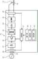
图1是表示实施方式所涉及的逆变器焊接机的结构的框图。FIG. 1 is a block diagram showing the configuration of an inverter welding machine according to the embodiment.
图2是表示晶闸管波形和逆变器波形的曲线图。Fig. 2 is a graph showing thyristor waveforms and inverter waveforms.
具体实施方式Detailed ways
以下,基于附图来对本公开的实施方式进行说明。另外,以下的优选的实施方式的说明本质上仅仅示例,并不意图限制本公开、其应用物或者其用途。Embodiments of the present disclosure will be described below based on the drawings. In addition, the description of the following preferred embodiments is merely an example in nature, and is not intended to limit the present disclosure, its application, or its use.
如图1所示,逆变器焊接机10向电极11提供焊接电流来对母材12进行电弧焊接。As shown in FIG. 1 , an
逆变器焊接机10具备:输入端子16、输入检测器20、第1整流器21、逆变器22、变压器23、第2整流器24、电抗器25、输出检测器26、控制部27、输入部30。The
输入端子16与交流电源15连接,从交流电源15接受交流电力。The
输入检测器20对从交流电源15输入的交流电压的频率进行检测,生成表示所检测的频率的第1输出信号。第1输出信号被发送给控制部27。The
第1整流器21与输入端子16连接。第1整流器21对交流电压进行整流并转换为直流电压。逆变器22与第1整流器21连接。逆变器22将通过第1整流器21转换的直流电压转换为规定的频率的交流电压。具体地,逆变器22包含未图示的多个开关元件。逆变器22通过对这些多个开关元件的接通断开动作进行切换,调整输出。The
变压器23与逆变器22连接。变压器23对逆变器22的输出电压进行降压。第2整流器24与变压器23连接。第2整流器24将通过变压器23来降压的输出电压进行整流来转换为直流电压。电抗器25与第2整流器24连接。电抗器25使第2整流器24的输出平滑化。The
输出检测器26对第2整流器24的输出值进行检测,生成表示所检测的输出值的第2输出信号。输出值例如是向电极11与母材12之间提供的焊接电流以及焊接电压。第2输出信号被发送给控制部27。The
输入部30例如是包含触摸面板、开关的用户接口界面。输入部30通过作业者的操作来接受各种设定值。输入部30具备选择部31和设定部32。The
选择部31选择性地切换波形模式,以使得提供给电极11的焊接电流的波形为逆变器波形或者晶闸管波形。具体地说,选择部31选择生成具有逆变器波形的焊接电流的第1波形模式和生成具有晶闸管波形的焊接电流的第2波形模式之中的一个。选择部31进一步生成表示第1波形模式和第2波形模式之中被选择的一个波形模式的第3输出信号。第3输出信号被发送给控制部27。The
设定部32对焊接电流的电流值以及频率进行设定。The setting
控制部27对逆变器22输出控制信号,对逆变器22的动作进行反馈控制,以使得得到用于适当地进行电弧焊接的焊接电力。The
具体地,控制部27对来自输入检测器20的第1输出信号、来自输出检测器26的第2输出信号、来自选择部31的第3输出信号进行接收。控制部27决定由选择部31选择的一个波形模式所对应的逆变器22的接通断开时间,基于决定的接通断开时间来控制逆变器22。所谓接通断开时间,例如是指脉冲宽度调制中使用的占空比。Specifically, the
例如,在通过设定部32从而电流值被设定为300A、通过选择部31从而选择了第1波形模式(逆变器波形)的情况下,控制部27以非常高的频率(几十kHz、例如从10kHz到100kHz的范围的任意频率)输出控制信号,控制逆变器22。由此,如图2所示,能够得到焊接电流以300A大致恒定的逆变器波形。具有逆变器波形的焊接电流包含具有20kHz至200kHz的范围的任意频率以及第1振幅的脉动电流。For example, when the current value is set to 300A by the setting
另一方面,在通过设定部32从而电流值被设定为300A、通过选择部31从而选择了第2波形模式(晶闸管波形)的情况下,控制部27基于来自输入检测器20的第1输出信号,决定焊接电流的频率。具有晶闸管波形的焊接电流包含具有100Hz或者120Hz的频率以及第2振幅的脉动电流。第2振幅大于第1振幅。例如,50Hz的晶闸管波形包含具有100Hz的频率的脉动电流。60Hz的晶闸管波形包含具有120Hz的频率的脉动电流。On the other hand, when the current value is set to 300A by the setting
例如,交流电源的频率在东日本为50Hz,在西日本为60Hz。在逆变器焊接机10被设置于东日本的现场的情况下,输入检测器20对50Hz的交流电压进行检测。For example, the frequency of AC power is 50 Hz in East Japan and 60 Hz in West Japan. When the
控制部27决定逆变器22的接通断开时间,以使得得到频率50Hz的晶闸管波形(包含具有100Hz的频率的脉动电流)。控制部27通过将基于决定的接通断开时间的控制信号输出给逆变器22,来控制逆变器22。由此,如图2所示,能够得到以设定的电流值(300A)为基准而焊接电流反复上下的晶闸管波形。The
如以上那样,本实施方式所涉及的逆变器焊接机10能够结合焊接作业者的迫切期望来切换逆变器波形和晶闸管波形。As mentioned above, the
此外,输入检测器20对交流电压的频率进行检测。控制部27能够对逆变器22进行控制,以使得成为与通过输入检测器20而检测的频率(焊接现场的交流电压的频率)相应的晶闸管波形。因此,焊接作业者无需手动进行与焊接现场相应的频率的切换,作业性提高。In addition, the
此外,通过利用设定部32来设定焊接电流的电流值以及频率,能够任意调整焊接电流的输出波形。In addition, by setting the current value and frequency of the welding current by the setting
例如,习惯了交流电压的频率为50Hz的地域处的焊接作业的焊接作业者由于出差等,可能在频率为60Hz的地域进行作业。该情况下,焊接作业者通过将焊接电流的频率设定为50Hz,能够得到与平时同样的焊接施工感觉、焊接结果。For example, a welding worker who is accustomed to welding in an area where the frequency of AC voltage is 50 Hz may perform work in an area where the frequency is 60 Hz due to a business trip or the like. In this case, by setting the frequency of the welding current to 50 Hz, the welding operator can obtain the same welding work feeling and welding result as usual.
另外,在设定部32中,也可以能够无级调整频率。In addition, in the
产业上的可利用性Industrial availability
如以上说明那样,本公开可得到能够通过一台焊接机来切换逆变器波形和晶闸管波形这一实用性高的效果,因此非常有用且产业上的可利用性较高。As explained above, since this indication can acquire the highly practical effect that an inverter waveform and a thyristor waveform can be switched with one welding machine, it is very useful and has high industrial applicability.
-符号说明--Symbol Description-
10 逆变器焊接机10 inverter welding machine
11 电极11 electrodes
12 母材12 base metal
20 输入检测器20 input detector
21 第1整流器21 1st rectifier
22 逆变器22 inverter
23 变压器23 Transformers
24 第2整流器24 2nd rectifier
26 输出检测器26 output detector
27 控制部27 Control Department
30 输入部30 input part
31 选择部31 Selection Department
32 设定部。32 Setting section.
Claims (3)
Translated fromChineseApplications Claiming Priority (3)
| Application Number | Priority Date | Filing Date | Title |
|---|---|---|---|
| JP2019-096717 | 2019-05-23 | ||
| JP2019096717 | 2019-05-23 | ||
| PCT/JP2020/011716WO2020235197A1 (en) | 2019-05-23 | 2020-03-17 | Inverter welder |
Publications (2)
| Publication Number | Publication Date |
|---|---|
| CN113825581A CN113825581A (en) | 2021-12-21 |
| CN113825581Btrue CN113825581B (en) | 2023-06-13 |
Family
ID=73458598
Family Applications (1)
| Application Number | Title | Priority Date | Filing Date |
|---|---|---|---|
| CN202080036490.4AActiveCN113825581B (en) | 2019-05-23 | 2020-03-17 | Inverter welding machine |
Country Status (3)
| Country | Link |
|---|---|
| JP (1) | JP7426561B2 (en) |
| CN (1) | CN113825581B (en) |
| WO (1) | WO2020235197A1 (en) |
Family Cites Families (6)
| Publication number | Priority date | Publication date | Assignee | Title |
|---|---|---|---|---|
| JPS54114452A (en)* | 1978-02-27 | 1979-09-06 | Shinko Electric Co Ltd | Welding current controlling method of high frequency arc welding machine |
| JP3003159B2 (en)* | 1989-12-28 | 2000-01-24 | 株式会社ダイヘン | AC arc welding power supply |
| JP3607648B2 (en)* | 2001-08-13 | 2005-01-05 | 株式会社三社電機製作所 | Manufacturing method of welding power supply device |
| JP3822842B2 (en)* | 2002-05-29 | 2006-09-20 | 株式会社ダイヘン | Power supply device for arc machining |
| WO2010116706A1 (en)* | 2009-04-08 | 2010-10-14 | パナソニック株式会社 | Dc power source device and inverter device and air-conditioner using these |
| US9960687B2 (en)* | 2016-06-06 | 2018-05-01 | General Electric Company | System and method for a DC/DC converter |
- 2020
- 2020-03-17JPJP2021520071Apatent/JP7426561B2/enactiveActive
- 2020-03-17WOPCT/JP2020/011716patent/WO2020235197A1/ennot_activeCeased
- 2020-03-17CNCN202080036490.4Apatent/CN113825581B/enactiveActive
Also Published As
| Publication number | Publication date |
|---|---|
| CN113825581A (en) | 2021-12-21 |
| JP7426561B2 (en) | 2024-02-02 |
| WO2020235197A1 (en) | 2020-11-26 |
| JPWO2020235197A1 (en) | 2020-11-26 |
Similar Documents
| Publication | Publication Date | Title |
|---|---|---|
| CN101003105B (en) | Synergic TIG welding system | |
| US6034350A (en) | Method and apparatus for initiating a welding arc using a background circuit | |
| KR100281315B1 (en) | Welding power supply and its manufacturing method | |
| EP1052051A2 (en) | Welding power supply for pulsed spray welding | |
| JP2001276971A (en) | Control method and apparatus for high frequency pulse welding machine | |
| US12103121B2 (en) | Methods and apparatus to control welding power and preheating power | |
| JP2020127969A (en) | Tig welding arc initiation | |
| JP2003311407A (en) | Welding machine | |
| CN113825581B (en) | Inverter welding machine | |
| US5643475A (en) | Power supply apparatus | |
| JP3231649B2 (en) | Consumable electrode type DC arc welding machine | |
| JP2012030275A (en) | Electric arc welder | |
| JPH0910937A (en) | Arc welding machine | |
| CN101543931B (en) | Arc spot welded device | |
| EP0474031A2 (en) | Inverter type power control unit for stud welding | |
| CN114406413A (en) | System and method for providing visual aids for selection of welding parameters | |
| CN111867770B (en) | System and method for providing welding-type power on multiple outputs | |
| JP4759233B2 (en) | Non-consumable electrode type gas shielded arc welding power supply | |
| US20250144732A1 (en) | Ac power stage bypass in a welding power source | |
| US20240316672A1 (en) | Regulation of arc characteristics in pulsed gas metal arc welding | |
| JP2686183B2 (en) | AC TIG welding machine | |
| JP2001259837A (en) | High frequency pulse welding method and apparatus | |
| JPWO2010097877A1 (en) | Arc welding machine | |
| JP2004166374A (en) | Power supply | |
| JP3607648B2 (en) | Manufacturing method of welding power supply device |
Legal Events
| Date | Code | Title | Description |
|---|---|---|---|
| PB01 | Publication | ||
| PB01 | Publication | ||
| SE01 | Entry into force of request for substantive examination | ||
| SE01 | Entry into force of request for substantive examination | ||
| GR01 | Patent grant | ||
| GR01 | Patent grant |