CN113823958B - Backboard connector assembly - Google Patents
Backboard connector assemblyDownload PDFInfo
- Publication number
- CN113823958B CN113823958BCN202110037232.4ACN202110037232ACN113823958BCN 113823958 BCN113823958 BCN 113823958BCN 202110037232 ACN202110037232 ACN 202110037232ACN 113823958 BCN113823958 BCN 113823958B
- Authority
- CN
- China
- Prior art keywords
- terminal
- backplane connector
- wall
- ground terminal
- protrusion
- Prior art date
- Legal status (The legal status is an assumption and is not a legal conclusion. Google has not performed a legal analysis and makes no representation as to the accuracy of the status listed.)
- Active
Links
Images


Classifications
- H—ELECTRICITY
- H01—ELECTRIC ELEMENTS
- H01R—ELECTRICALLY-CONDUCTIVE CONNECTIONS; STRUCTURAL ASSOCIATIONS OF A PLURALITY OF MUTUALLY-INSULATED ELECTRICAL CONNECTING ELEMENTS; COUPLING DEVICES; CURRENT COLLECTORS
- H01R13/00—Details of coupling devices of the kinds covered by groups H01R12/70 or H01R24/00 - H01R33/00
- H01R13/646—Details of coupling devices of the kinds covered by groups H01R12/70 or H01R24/00 - H01R33/00 specially adapted for high-frequency, e.g. structures providing an impedance match or phase match
- H01R13/6461—Means for preventing cross-talk
- H01R13/6471—Means for preventing cross-talk by special arrangement of ground and signal conductors, e.g. GSGS [Ground-Signal-Ground-Signal]
- H—ELECTRICITY
- H01—ELECTRIC ELEMENTS
- H01R—ELECTRICALLY-CONDUCTIVE CONNECTIONS; STRUCTURAL ASSOCIATIONS OF A PLURALITY OF MUTUALLY-INSULATED ELECTRICAL CONNECTING ELEMENTS; COUPLING DEVICES; CURRENT COLLECTORS
- H01R13/00—Details of coupling devices of the kinds covered by groups H01R12/70 or H01R24/00 - H01R33/00
- H01R13/646—Details of coupling devices of the kinds covered by groups H01R12/70 or H01R24/00 - H01R33/00 specially adapted for high-frequency, e.g. structures providing an impedance match or phase match
- H—ELECTRICITY
- H01—ELECTRIC ELEMENTS
- H01R—ELECTRICALLY-CONDUCTIVE CONNECTIONS; STRUCTURAL ASSOCIATIONS OF A PLURALITY OF MUTUALLY-INSULATED ELECTRICAL CONNECTING ELEMENTS; COUPLING DEVICES; CURRENT COLLECTORS
- H01R12/00—Structural associations of a plurality of mutually-insulated electrical connecting elements, specially adapted for printed circuits, e.g. printed circuit boards [PCB], flat or ribbon cables, or like generally planar structures, e.g. terminal strips, terminal blocks; Coupling devices specially adapted for printed circuits, flat or ribbon cables, or like generally planar structures; Terminals specially adapted for contact with, or insertion into, printed circuits, flat or ribbon cables, or like generally planar structures
- H01R12/50—Fixed connections
- H01R12/51—Fixed connections for rigid printed circuits or like structures
- H01R12/55—Fixed connections for rigid printed circuits or like structures characterised by the terminals
- H01R12/58—Fixed connections for rigid printed circuits or like structures characterised by the terminals terminals for insertion into holes
- H01R12/585—Terminals having a press fit or a compliant portion and a shank passing through a hole in the printed circuit board
- H—ELECTRICITY
- H01—ELECTRIC ELEMENTS
- H01R—ELECTRICALLY-CONDUCTIVE CONNECTIONS; STRUCTURAL ASSOCIATIONS OF A PLURALITY OF MUTUALLY-INSULATED ELECTRICAL CONNECTING ELEMENTS; COUPLING DEVICES; CURRENT COLLECTORS
- H01R12/00—Structural associations of a plurality of mutually-insulated electrical connecting elements, specially adapted for printed circuits, e.g. printed circuit boards [PCB], flat or ribbon cables, or like generally planar structures, e.g. terminal strips, terminal blocks; Coupling devices specially adapted for printed circuits, flat or ribbon cables, or like generally planar structures; Terminals specially adapted for contact with, or insertion into, printed circuits, flat or ribbon cables, or like generally planar structures
- H01R12/70—Coupling devices
- H01R12/71—Coupling devices for rigid printing circuits or like structures
- H01R12/712—Coupling devices for rigid printing circuits or like structures co-operating with the surface of the printed circuit or with a coupling device exclusively provided on the surface of the printed circuit
- H01R12/716—Coupling device provided on the PCB
- H—ELECTRICITY
- H01—ELECTRIC ELEMENTS
- H01R—ELECTRICALLY-CONDUCTIVE CONNECTIONS; STRUCTURAL ASSOCIATIONS OF A PLURALITY OF MUTUALLY-INSULATED ELECTRICAL CONNECTING ELEMENTS; COUPLING DEVICES; CURRENT COLLECTORS
- H01R12/00—Structural associations of a plurality of mutually-insulated electrical connecting elements, specially adapted for printed circuits, e.g. printed circuit boards [PCB], flat or ribbon cables, or like generally planar structures, e.g. terminal strips, terminal blocks; Coupling devices specially adapted for printed circuits, flat or ribbon cables, or like generally planar structures; Terminals specially adapted for contact with, or insertion into, printed circuits, flat or ribbon cables, or like generally planar structures
- H01R12/70—Coupling devices
- H01R12/71—Coupling devices for rigid printing circuits or like structures
- H01R12/72—Coupling devices for rigid printing circuits or like structures coupling with the edge of the rigid printed circuits or like structures
- H01R12/722—Coupling devices for rigid printing circuits or like structures coupling with the edge of the rigid printed circuits or like structures coupling devices mounted on the edge of the printed circuits
- H01R12/724—Coupling devices for rigid printing circuits or like structures coupling with the edge of the rigid printed circuits or like structures coupling devices mounted on the edge of the printed circuits containing contact members forming a right angle
- H—ELECTRICITY
- H01—ELECTRIC ELEMENTS
- H01R—ELECTRICALLY-CONDUCTIVE CONNECTIONS; STRUCTURAL ASSOCIATIONS OF A PLURALITY OF MUTUALLY-INSULATED ELECTRICAL CONNECTING ELEMENTS; COUPLING DEVICES; CURRENT COLLECTORS
- H01R13/00—Details of coupling devices of the kinds covered by groups H01R12/70 or H01R24/00 - H01R33/00
- H01R13/02—Contact members
- H01R13/20—Pins, blades, or sockets shaped, or provided with separate member, to retain co-operating parts together
- H—ELECTRICITY
- H01—ELECTRIC ELEMENTS
- H01R—ELECTRICALLY-CONDUCTIVE CONNECTIONS; STRUCTURAL ASSOCIATIONS OF A PLURALITY OF MUTUALLY-INSULATED ELECTRICAL CONNECTING ELEMENTS; COUPLING DEVICES; CURRENT COLLECTORS
- H01R13/00—Details of coupling devices of the kinds covered by groups H01R12/70 or H01R24/00 - H01R33/00
- H01R13/40—Securing contact members in or to a base or case; Insulating of contact members
- H—ELECTRICITY
- H01—ELECTRIC ELEMENTS
- H01R—ELECTRICALLY-CONDUCTIVE CONNECTIONS; STRUCTURAL ASSOCIATIONS OF A PLURALITY OF MUTUALLY-INSULATED ELECTRICAL CONNECTING ELEMENTS; COUPLING DEVICES; CURRENT COLLECTORS
- H01R13/00—Details of coupling devices of the kinds covered by groups H01R12/70 or H01R24/00 - H01R33/00
- H01R13/46—Bases; Cases
- H01R13/502—Bases; Cases composed of different pieces
- H01R13/504—Bases; Cases composed of different pieces different pieces being moulded, cemented, welded, e.g. ultrasonic, or swaged together
- H—ELECTRICITY
- H01—ELECTRIC ELEMENTS
- H01R—ELECTRICALLY-CONDUCTIVE CONNECTIONS; STRUCTURAL ASSOCIATIONS OF A PLURALITY OF MUTUALLY-INSULATED ELECTRICAL CONNECTING ELEMENTS; COUPLING DEVICES; CURRENT COLLECTORS
- H01R13/00—Details of coupling devices of the kinds covered by groups H01R12/70 or H01R24/00 - H01R33/00
- H01R13/46—Bases; Cases
- H01R13/514—Bases; Cases composed as a modular blocks or assembly, i.e. composed of co-operating parts provided with contact members or holding contact members between them
- H—ELECTRICITY
- H01—ELECTRIC ELEMENTS
- H01R—ELECTRICALLY-CONDUCTIVE CONNECTIONS; STRUCTURAL ASSOCIATIONS OF A PLURALITY OF MUTUALLY-INSULATED ELECTRICAL CONNECTING ELEMENTS; COUPLING DEVICES; CURRENT COLLECTORS
- H01R13/00—Details of coupling devices of the kinds covered by groups H01R12/70 or H01R24/00 - H01R33/00
- H01R13/46—Bases; Cases
- H01R13/516—Means for holding or embracing insulating body, e.g. casing, hoods
- H01R13/518—Means for holding or embracing insulating body, e.g. casing, hoods for holding or embracing several coupling parts, e.g. frames
- H—ELECTRICITY
- H01—ELECTRIC ELEMENTS
- H01R—ELECTRICALLY-CONDUCTIVE CONNECTIONS; STRUCTURAL ASSOCIATIONS OF A PLURALITY OF MUTUALLY-INSULATED ELECTRICAL CONNECTING ELEMENTS; COUPLING DEVICES; CURRENT COLLECTORS
- H01R13/00—Details of coupling devices of the kinds covered by groups H01R12/70 or H01R24/00 - H01R33/00
- H01R13/646—Details of coupling devices of the kinds covered by groups H01R12/70 or H01R24/00 - H01R33/00 specially adapted for high-frequency, e.g. structures providing an impedance match or phase match
- H01R13/6473—Impedance matching
- H—ELECTRICITY
- H01—ELECTRIC ELEMENTS
- H01R—ELECTRICALLY-CONDUCTIVE CONNECTIONS; STRUCTURAL ASSOCIATIONS OF A PLURALITY OF MUTUALLY-INSULATED ELECTRICAL CONNECTING ELEMENTS; COUPLING DEVICES; CURRENT COLLECTORS
- H01R13/00—Details of coupling devices of the kinds covered by groups H01R12/70 or H01R24/00 - H01R33/00
- H01R13/648—Protective earth or shield arrangements on coupling devices, e.g. anti-static shielding
- H01R13/652—Protective earth or shield arrangements on coupling devices, e.g. anti-static shielding with earth pin, blade or socket
- H—ELECTRICITY
- H01—ELECTRIC ELEMENTS
- H01R—ELECTRICALLY-CONDUCTIVE CONNECTIONS; STRUCTURAL ASSOCIATIONS OF A PLURALITY OF MUTUALLY-INSULATED ELECTRICAL CONNECTING ELEMENTS; COUPLING DEVICES; CURRENT COLLECTORS
- H01R13/00—Details of coupling devices of the kinds covered by groups H01R12/70 or H01R24/00 - H01R33/00
- H01R13/648—Protective earth or shield arrangements on coupling devices, e.g. anti-static shielding
- H01R13/658—High frequency shielding arrangements, e.g. against EMI [Electro-Magnetic Interference] or EMP [Electro-Magnetic Pulse]
- H01R13/6581—Shield structure
- H01R13/6582—Shield structure with resilient means for engaging mating connector
- H01R13/6583—Shield structure with resilient means for engaging mating connector with separate conductive resilient members between mating shield members
- H01R13/6584—Shield structure with resilient means for engaging mating connector with separate conductive resilient members between mating shield members formed by conductive elastomeric members, e.g. flat gaskets or O-rings
- H—ELECTRICITY
- H01—ELECTRIC ELEMENTS
- H01R—ELECTRICALLY-CONDUCTIVE CONNECTIONS; STRUCTURAL ASSOCIATIONS OF A PLURALITY OF MUTUALLY-INSULATED ELECTRICAL CONNECTING ELEMENTS; COUPLING DEVICES; CURRENT COLLECTORS
- H01R13/00—Details of coupling devices of the kinds covered by groups H01R12/70 or H01R24/00 - H01R33/00
- H01R13/648—Protective earth or shield arrangements on coupling devices, e.g. anti-static shielding
- H01R13/658—High frequency shielding arrangements, e.g. against EMI [Electro-Magnetic Interference] or EMP [Electro-Magnetic Pulse]
- H01R13/6581—Shield structure
- H01R13/6585—Shielding material individually surrounding or interposed between mutually spaced contacts
- H01R13/6586—Shielding material individually surrounding or interposed between mutually spaced contacts for separating multiple connector modules
- H01R13/6587—Shielding material individually surrounding or interposed between mutually spaced contacts for separating multiple connector modules for mounting on PCBs
- H—ELECTRICITY
- H01—ELECTRIC ELEMENTS
- H01R—ELECTRICALLY-CONDUCTIVE CONNECTIONS; STRUCTURAL ASSOCIATIONS OF A PLURALITY OF MUTUALLY-INSULATED ELECTRICAL CONNECTING ELEMENTS; COUPLING DEVICES; CURRENT COLLECTORS
- H01R13/00—Details of coupling devices of the kinds covered by groups H01R12/70 or H01R24/00 - H01R33/00
- H01R13/648—Protective earth or shield arrangements on coupling devices, e.g. anti-static shielding
- H01R13/658—High frequency shielding arrangements, e.g. against EMI [Electro-Magnetic Interference] or EMP [Electro-Magnetic Pulse]
- H01R13/6581—Shield structure
- H01R13/6585—Shielding material individually surrounding or interposed between mutually spaced contacts
- H01R13/6588—Shielding material individually surrounding or interposed between mutually spaced contacts with through openings for individual contacts
- H—ELECTRICITY
- H01—ELECTRIC ELEMENTS
- H01R—ELECTRICALLY-CONDUCTIVE CONNECTIONS; STRUCTURAL ASSOCIATIONS OF A PLURALITY OF MUTUALLY-INSULATED ELECTRICAL CONNECTING ELEMENTS; COUPLING DEVICES; CURRENT COLLECTORS
- H01R13/00—Details of coupling devices of the kinds covered by groups H01R12/70 or H01R24/00 - H01R33/00
- H01R13/648—Protective earth or shield arrangements on coupling devices, e.g. anti-static shielding
- H01R13/658—High frequency shielding arrangements, e.g. against EMI [Electro-Magnetic Interference] or EMP [Electro-Magnetic Pulse]
- H01R13/6591—Specific features or arrangements of connection of shield to conductive members
- H—ELECTRICITY
- H01—ELECTRIC ELEMENTS
- H01R—ELECTRICALLY-CONDUCTIVE CONNECTIONS; STRUCTURAL ASSOCIATIONS OF A PLURALITY OF MUTUALLY-INSULATED ELECTRICAL CONNECTING ELEMENTS; COUPLING DEVICES; CURRENT COLLECTORS
- H01R43/00—Apparatus or processes specially adapted for manufacturing, assembling, maintaining, or repairing of line connectors or current collectors or for joining electric conductors
- H01R43/20—Apparatus or processes specially adapted for manufacturing, assembling, maintaining, or repairing of line connectors or current collectors or for joining electric conductors for assembling or disassembling contact members with insulating base, case or sleeve
- H01R43/24—Assembling by moulding on contact members
- H—ELECTRICITY
- H05—ELECTRIC TECHNIQUES NOT OTHERWISE PROVIDED FOR
- H05K—PRINTED CIRCUITS; CASINGS OR CONSTRUCTIONAL DETAILS OF ELECTRIC APPARATUS; MANUFACTURE OF ASSEMBLAGES OF ELECTRICAL COMPONENTS
- H05K1/00—Printed circuits
- H05K1/02—Details
- H05K1/11—Printed elements for providing electric connections to or between printed circuits
- H05K1/115—Via connections; Lands around holes or via connections
- H—ELECTRICITY
- H05—ELECTRIC TECHNIQUES NOT OTHERWISE PROVIDED FOR
- H05K—PRINTED CIRCUITS; CASINGS OR CONSTRUCTIONAL DETAILS OF ELECTRIC APPARATUS; MANUFACTURE OF ASSEMBLAGES OF ELECTRICAL COMPONENTS
- H05K3/00—Apparatus or processes for manufacturing printed circuits
- H05K3/30—Assembling printed circuits with electric components, e.g. with resistor
- H05K3/306—Lead-in-hole components, e.g. affixing or retention before soldering, spacing means
- H—ELECTRICITY
- H05—ELECTRIC TECHNIQUES NOT OTHERWISE PROVIDED FOR
- H05K—PRINTED CIRCUITS; CASINGS OR CONSTRUCTIONAL DETAILS OF ELECTRIC APPARATUS; MANUFACTURE OF ASSEMBLAGES OF ELECTRICAL COMPONENTS
- H05K3/00—Apparatus or processes for manufacturing printed circuits
- H05K3/30—Assembling printed circuits with electric components, e.g. with resistor
- H05K3/32—Assembling printed circuits with electric components, e.g. with resistor electrically connecting electric components or wires to printed circuits
- H05K3/34—Assembling printed circuits with electric components, e.g. with resistor electrically connecting electric components or wires to printed circuits by soldering
- H05K3/3447—Lead-in-hole components
- H—ELECTRICITY
- H01—ELECTRIC ELEMENTS
- H01R—ELECTRICALLY-CONDUCTIVE CONNECTIONS; STRUCTURAL ASSOCIATIONS OF A PLURALITY OF MUTUALLY-INSULATED ELECTRICAL CONNECTING ELEMENTS; COUPLING DEVICES; CURRENT COLLECTORS
- H01R12/00—Structural associations of a plurality of mutually-insulated electrical connecting elements, specially adapted for printed circuits, e.g. printed circuit boards [PCB], flat or ribbon cables, or like generally planar structures, e.g. terminal strips, terminal blocks; Coupling devices specially adapted for printed circuits, flat or ribbon cables, or like generally planar structures; Terminals specially adapted for contact with, or insertion into, printed circuits, flat or ribbon cables, or like generally planar structures
- H01R12/70—Coupling devices
- H01R12/71—Coupling devices for rigid printing circuits or like structures
- H01R12/712—Coupling devices for rigid printing circuits or like structures co-operating with the surface of the printed circuit or with a coupling device exclusively provided on the surface of the printed circuit
- H—ELECTRICITY
- H01—ELECTRIC ELEMENTS
- H01R—ELECTRICALLY-CONDUCTIVE CONNECTIONS; STRUCTURAL ASSOCIATIONS OF A PLURALITY OF MUTUALLY-INSULATED ELECTRICAL CONNECTING ELEMENTS; COUPLING DEVICES; CURRENT COLLECTORS
- H01R12/00—Structural associations of a plurality of mutually-insulated electrical connecting elements, specially adapted for printed circuits, e.g. printed circuit boards [PCB], flat or ribbon cables, or like generally planar structures, e.g. terminal strips, terminal blocks; Coupling devices specially adapted for printed circuits, flat or ribbon cables, or like generally planar structures; Terminals specially adapted for contact with, or insertion into, printed circuits, flat or ribbon cables, or like generally planar structures
- H01R12/70—Coupling devices
- H01R12/71—Coupling devices for rigid printing circuits or like structures
- H01R12/72—Coupling devices for rigid printing circuits or like structures coupling with the edge of the rigid printed circuits or like structures
- H01R12/722—Coupling devices for rigid printing circuits or like structures coupling with the edge of the rigid printed circuits or like structures coupling devices mounted on the edge of the printed circuits
- H—ELECTRICITY
- H01—ELECTRIC ELEMENTS
- H01R—ELECTRICALLY-CONDUCTIVE CONNECTIONS; STRUCTURAL ASSOCIATIONS OF A PLURALITY OF MUTUALLY-INSULATED ELECTRICAL CONNECTING ELEMENTS; COUPLING DEVICES; CURRENT COLLECTORS
- H01R13/00—Details of coupling devices of the kinds covered by groups H01R12/70 or H01R24/00 - H01R33/00
- H01R13/46—Bases; Cases
- H01R13/502—Bases; Cases composed of different pieces
- H—ELECTRICITY
- H01—ELECTRIC ELEMENTS
- H01R—ELECTRICALLY-CONDUCTIVE CONNECTIONS; STRUCTURAL ASSOCIATIONS OF A PLURALITY OF MUTUALLY-INSULATED ELECTRICAL CONNECTING ELEMENTS; COUPLING DEVICES; CURRENT COLLECTORS
- H01R13/00—Details of coupling devices of the kinds covered by groups H01R12/70 or H01R24/00 - H01R33/00
- H01R13/646—Details of coupling devices of the kinds covered by groups H01R12/70 or H01R24/00 - H01R33/00 specially adapted for high-frequency, e.g. structures providing an impedance match or phase match
- H01R13/6473—Impedance matching
- H01R13/6474—Impedance matching by variation of conductive properties, e.g. by dimension variations
- H—ELECTRICITY
- H01—ELECTRIC ELEMENTS
- H01R—ELECTRICALLY-CONDUCTIVE CONNECTIONS; STRUCTURAL ASSOCIATIONS OF A PLURALITY OF MUTUALLY-INSULATED ELECTRICAL CONNECTING ELEMENTS; COUPLING DEVICES; CURRENT COLLECTORS
- H01R13/00—Details of coupling devices of the kinds covered by groups H01R12/70 or H01R24/00 - H01R33/00
- H01R13/648—Protective earth or shield arrangements on coupling devices, e.g. anti-static shielding
- H01R13/658—High frequency shielding arrangements, e.g. against EMI [Electro-Magnetic Interference] or EMP [Electro-Magnetic Pulse]
- H01R13/6581—Shield structure
- H01R13/6582—Shield structure with resilient means for engaging mating connector
- H—ELECTRICITY
- H05—ELECTRIC TECHNIQUES NOT OTHERWISE PROVIDED FOR
- H05K—PRINTED CIRCUITS; CASINGS OR CONSTRUCTIONAL DETAILS OF ELECTRIC APPARATUS; MANUFACTURE OF ASSEMBLAGES OF ELECTRICAL COMPONENTS
- H05K2201/00—Indexing scheme relating to printed circuits covered by H05K1/00
- H05K2201/09—Shape and layout
- H05K2201/09209—Shape and layout details of conductors
- H05K2201/09218—Conductive traces
- H05K2201/09236—Parallel layout
- H—ELECTRICITY
- H05—ELECTRIC TECHNIQUES NOT OTHERWISE PROVIDED FOR
- H05K—PRINTED CIRCUITS; CASINGS OR CONSTRUCTIONAL DETAILS OF ELECTRIC APPARATUS; MANUFACTURE OF ASSEMBLAGES OF ELECTRICAL COMPONENTS
- H05K2201/00—Indexing scheme relating to printed circuits covered by H05K1/00
- H05K2201/10—Details of components or other objects attached to or integrated in a printed circuit board
- H05K2201/10007—Types of components
- H05K2201/10189—Non-printed connector
- H—ELECTRICITY
- H05—ELECTRIC TECHNIQUES NOT OTHERWISE PROVIDED FOR
- H05K—PRINTED CIRCUITS; CASINGS OR CONSTRUCTIONAL DETAILS OF ELECTRIC APPARATUS; MANUFACTURE OF ASSEMBLAGES OF ELECTRICAL COMPONENTS
- H05K2201/00—Indexing scheme relating to printed circuits covered by H05K1/00
- H05K2201/10—Details of components or other objects attached to or integrated in a printed circuit board
- H05K2201/10227—Other objects, e.g. metallic pieces
- H05K2201/10371—Shields or metal cases
- H—ELECTRICITY
- H05—ELECTRIC TECHNIQUES NOT OTHERWISE PROVIDED FOR
- H05K—PRINTED CIRCUITS; CASINGS OR CONSTRUCTIONAL DETAILS OF ELECTRIC APPARATUS; MANUFACTURE OF ASSEMBLAGES OF ELECTRICAL COMPONENTS
- H05K2201/00—Indexing scheme relating to printed circuits covered by H05K1/00
- H05K2201/10—Details of components or other objects attached to or integrated in a printed circuit board
- H05K2201/10613—Details of electrical connections of non-printed components, e.g. special leads
- H05K2201/10742—Details of leads
- H05K2201/1075—Shape details
- H05K2201/1078—Leads having locally deformed portion, e.g. for retention
- H—ELECTRICITY
- H05—ELECTRIC TECHNIQUES NOT OTHERWISE PROVIDED FOR
- H05K—PRINTED CIRCUITS; CASINGS OR CONSTRUCTIONAL DETAILS OF ELECTRIC APPARATUS; MANUFACTURE OF ASSEMBLAGES OF ELECTRICAL COMPONENTS
- H05K2201/00—Indexing scheme relating to printed circuits covered by H05K1/00
- H05K2201/10—Details of components or other objects attached to or integrated in a printed circuit board
- H05K2201/10613—Details of electrical connections of non-printed components, e.g. special leads
- H05K2201/10742—Details of leads
- H05K2201/1075—Shape details
- H05K2201/10871—Leads having an integral insert stop
- Y—GENERAL TAGGING OF NEW TECHNOLOGICAL DEVELOPMENTS; GENERAL TAGGING OF CROSS-SECTIONAL TECHNOLOGIES SPANNING OVER SEVERAL SECTIONS OF THE IPC; TECHNICAL SUBJECTS COVERED BY FORMER USPC CROSS-REFERENCE ART COLLECTIONS [XRACs] AND DIGESTS
- Y02—TECHNOLOGIES OR APPLICATIONS FOR MITIGATION OR ADAPTATION AGAINST CLIMATE CHANGE
- Y02E—REDUCTION OF GREENHOUSE GAS [GHG] EMISSIONS, RELATED TO ENERGY GENERATION, TRANSMISSION OR DISTRIBUTION
- Y02E10/00—Energy generation through renewable energy sources
- Y02E10/50—Photovoltaic [PV] energy
Landscapes
- Engineering & Computer Science (AREA)
- Manufacturing & Machinery (AREA)
- Microelectronics & Electronic Packaging (AREA)
- Details Of Connecting Devices For Male And Female Coupling (AREA)
- Mechanical Coupling Of Light Guides (AREA)
- Magnetic Heads (AREA)
Abstract
Description
Translated fromChinese本发明要求了申请日为2020年06月19日,申请号为202010567796.4,发明创造名称为“背板连接器组件”的中国专利申请的优先权,其全部内容通过引用结合在本申请中。The present invention claims the priority of a Chinese patent application with an application date of June 19, 2020, an application number of 202010567796.4, and an invention titled "Backplane Connector Assembly", the entire contents of which are incorporated in this application by reference.
技术领域technical field
本发明涉及一种背板连接器组件,属于连接器技术领域。The invention relates to a backplane connector assembly, which belongs to the technical field of connectors.
背景技术Background technique
现有的背板连接器组件通常包括公端连接器与母端连接器。公端连接器通常包括公端壳体以及安装于公端壳体的若干公端插接模组。每一公端插接模组包括绝缘框架、嵌入成型在绝缘框架中的若干公端导电端子以及安装在绝缘框架至少一侧的第一金属屏蔽片。所述公端导电端子通常包括第一对接部以及垂直于第一对接部的第一安装脚。Existing backplane connector assemblies generally include male connectors and female connectors. A male connector generally includes a male housing and several male plug-in modules mounted on the male housing. Each male plug-in module includes an insulating frame, several male conductive terminals embedded in the insulating frame, and a first metal shielding sheet installed on at least one side of the insulating frame. The male conductive terminal generally includes a first docking portion and a first mounting foot perpendicular to the first docking portion.
母端连接器通常包括母端壳体以及安装于母端壳体的若干母端插接模组。每一母端插接模组包括绝缘框架、嵌入成型在绝缘框架中的若干母端导电端子以及安装在绝缘框架至少一侧的第二金属屏蔽片。所述母端导电端子通常包括第二对接部以及垂直于第二对接部的第二安装脚。The receptacle connector usually includes a receptacle housing and several receptacle plug-in modules mounted on the receptacle housing. Each receptacle plug-in module includes an insulating frame, a plurality of receptacle conductive terminals embedded in the insulating frame, and a second metal shielding sheet installed on at least one side of the insulating frame. The female conductive terminal generally includes a second docking portion and a second mounting foot perpendicular to the second docking portion.
所述第一安装脚与所述第二安装脚通常安装于电路板上。然而,现有的背板连接器的导电端子结构设计比较复杂。The first mounting feet and the second mounting feet are usually mounted on a circuit board. However, the structure design of the conductive terminals of the existing backplane connector is relatively complicated.
发明内容Contents of the invention
本发明的目的在于提供一种导电端子结构简单的背板连接器组件。The object of the present invention is to provide a backplane connector assembly with simple conductive terminal structure.
为实现上述目的,本发明采用如下技术方案:一种背板连接器组件,包括第一背板连接器以及与所述第一背板连接器对接的第二背板连接器,其中所述第一背板连接器包括第一端子模组,所述第一端子模组包括:To achieve the above object, the present invention adopts the following technical solution: a backplane connector assembly, including a first backplane connector and a second backplane connector docked with the first backplane connector, wherein the first backplane connector A backplane connector includes a first terminal module, the first terminal module includes:
若干第一导电端子,所述第一导电端子包括第一对接部、第一尾部以及位于所述第一对接部与所述第一尾部之间的第一连接部;a plurality of first conductive terminals, the first conductive terminal includes a first docking portion, a first tail portion, and a first connection portion between the first docking portion and the first tail portion;
第一金属屏蔽片,所述第一金属屏蔽片设有第一延伸部;以及a first metal shielding sheet provided with a first extension; and
第二金属屏蔽片,所述第二金属屏蔽片设有第二延伸部;a second metal shielding sheet, the second metal shielding sheet is provided with a second extension;
所述第一导电端子包括第一差分信号端子、第一接地端子以及第二接地端子,其中所述第一差分信号端子位于所述第一接地端子与所述第二接地端子之间;The first conductive terminal includes a first differential signal terminal, a first ground terminal, and a second ground terminal, wherein the first differential signal terminal is located between the first ground terminal and the second ground terminal;
所述第二背板连接器包括第二端子模组,所述第二端子模组包括与所述第一差分信号端子对接的第二差分信号端子;The second backplane connector includes a second terminal module, and the second terminal module includes a second differential signal terminal docked with the first differential signal terminal;
所述第一对接部、所述第一连接部和所述第一尾部沿对接方向延伸;The first docking portion, the first connecting portion and the first tail portion extend along a docking direction;
所述第一延伸部、所述第二延伸部、所述第一接地端子的第一对接部以及所述第二接地端子的第一对接部围成屏蔽腔体,所述第一差分信号端子的第一对接部位于所述屏蔽腔体中;The first extension portion, the second extension portion, the first abutting portion of the first ground terminal, and the first abutting portion of the second ground terminal enclose a shielding cavity, and the first differential signal terminal The first docking part is located in the shielding cavity;
所述第二背板连接器还包括环绕在所述第二差分信号端子的外围的金属屏蔽围绕件,所述金属屏蔽围绕件收容于所述屏蔽腔体中。The second backplane connector further includes a metal shielding surrounding part surrounding the periphery of the second differential signal terminal, and the metal shielding surrounding part is accommodated in the shielding cavity.
作为本发明进一步改进的技术方案,所述第一背板连接器包括第一壳体,所述第一壳体包括第一本体部、自所述第一本体部的一端延伸的第一壁部以及自所述第一本体部的另一相对端延伸的第二壁部,所述第一壁部设有若干第一插槽,所述第二壁部设有若干第二插槽,相互连通的所述第一插槽和所述第二插槽形成了安装插槽,所述第一端子模组的一部分收容在所述安装插槽中;As a further improved technical solution of the present invention, the first backplane connector includes a first housing, the first housing includes a first body portion, a first wall portion extending from one end of the first body portion and a second wall portion extending from the other opposite end of the first body portion, the first wall portion is provided with a plurality of first slots, and the second wall portion is provided with a plurality of second slots, communicating with each other The first slot and the second slot form an installation slot, and a part of the first terminal module is accommodated in the installation slot;
所述第二背板连接器包括第二壳体,所述第二壳体设有围绕的壁部以及至少由所述壁部围成的收容空间,所述金属屏蔽围绕件凸伸入所述收容空间,所述第一壳体收容于所述收容空间。The second backplane connector includes a second housing, the second housing is provided with a surrounding wall and a receiving space at least surrounded by the wall, and the metal shielding surrounding part protrudes into the The accommodation space, the first casing is accommodated in the accommodation space.
作为本发明进一步改进的技术方案,所述第一壁部设有与所述第一插槽相连通的第一锁扣槽,所述第二壁部设有与所述第二插槽相连通的第二锁扣槽,所述第一锁扣槽和所述第二锁扣槽锁扣所述第一端子模组的一端。As a further improved technical solution of the present invention, the first wall part is provided with a first locking groove communicated with the first slot, and the second wall part is provided with a lock slot communicated with the second slot. The first locking slot and the second locking slot lock one end of the first terminal module.
作为本发明进一步改进的技术方案,所述第一背板连接器包括与所述第一壳体分开设置的安装壳体,所述安装壳体包括靠近所述第一壳体的第一端面、与所述第一端面相对的第一安装面以及贯穿所述第一端面和所述第一安装面的若干安装收容槽,所述第一端子模组的另一部分收容在所述安装收容槽中。As a further improved technical solution of the present invention, the first backplane connector includes an installation housing that is separately provided from the first housing, and the installation housing includes a first end surface close to the first housing, A first installation surface opposite to the first end surface and a plurality of installation accommodation grooves passing through the first end surface and the first installation surface, the other part of the first terminal module is accommodated in the installation accommodation grooves .
作为本发明进一步改进的技术方案,所述安装壳体设有第三壁部,所述第三壁部设有与所述安装收容槽相连通的第三锁扣槽,所述第三锁扣槽锁扣所述第一端子模组的另一端。As a further improved technical solution of the present invention, the installation housing is provided with a third wall part, and the third wall part is provided with a third lock slot connected with the installation storage slot, and the third lock The slot locks the other end of the first terminal module.
作为本发明进一步改进的技术方案,所述第一端子模组包括固定所述第一导电端子的绝缘支架,所述绝缘支架包括卡持于所述第一锁扣槽内的第一锁扣凸起、卡持于所述第二锁扣槽内的第二锁扣凸起、以及卡持于所述第三锁扣槽内的第三锁扣凸起,所述第一锁扣凸起、所述第二锁扣凸起和所述第三锁扣凸起为弹性凸起或者非弹性凸起。As a further improved technical solution of the present invention, the first terminal module includes an insulating bracket for fixing the first conductive terminal, and the insulating bracket includes a first locking protrusion that is clamped in the first locking groove. The second lock projection held in the second lock groove, and the third lock projection held in the third lock groove, the first lock projection, The second locking protrusion and the third locking protrusion are elastic protrusions or non-elastic protrusions.
作为本发明进一步改进的技术方案,所述安装壳体设有自所述第一安装面向所述第一端面的方向凹陷而成的第一安装空间,所述第一背板连接器包括安装在所述第一安装空间中的第一固持块,所述第一固持块设有让所述第一尾部穿过的若干第一定位穿孔;As a further improved technical solution of the present invention, the installation housing is provided with a first installation space that is recessed from the first installation surface in the direction of the first end surface, and the first backplane connector includes a The first holding block in the first installation space, the first holding block is provided with a plurality of first positioning through holes for the first tail to pass through;
所述第二壳体设有第二安装面以及自所述第二安装面凹陷而成的第二安装空间,所述第二背板连接器包括安装在所述第二安装空间中的第二固持块,所述第二固持块设有让所述第二差分信号端子的第二尾部穿过的若干第二定位穿孔。The second housing is provided with a second installation surface and a second installation space recessed from the second installation surface, and the second backplane connector includes a second installation space installed in the second installation space. A holding block, the second holding block is provided with a plurality of second positioning through holes through which the second tails of the second differential signal terminals pass.
作为本发明进一步改进的技术方案,所述第一固持块由电镀塑胶或者导电塑胶制成,所述第二固持块由电镀塑胶或者导电塑胶制成。As a further improved technical solution of the present invention, the first holding block is made of electroplating plastic or conductive plastic, and the second holding block is made of electroplating plastic or conductive plastic.
作为本发明进一步改进的技术方案,所述第一端子模组包括固定所述第一导电端子的绝缘支架,所述绝缘支架包括第一前壁、第一后壁、在前后方向上位于所述第一前壁和所述第一后壁之间的加强壁、位于所述第一前壁和所述加强壁之间的第一镂空部以及位于所述加强壁和所述第一后壁之间的第二镂空部,所述第一连接部固定于所述第一前壁、所述加强壁以及所述第一后壁,且所述第一连接部部分暴露于所述第一镂空部和所述第二镂空部中。As a further improved technical solution of the present invention, the first terminal module includes an insulating support for fixing the first conductive terminal, and the insulating support includes a first front wall, a first rear wall, The reinforcement wall between the first front wall and the first rear wall, the first hollow portion between the first front wall and the reinforcement wall, and the reinforcement wall and the first rear wall The second hollow part between, the first connecting part is fixed to the first front wall, the reinforcing wall and the first rear wall, and the first connecting part is partially exposed to the first hollow part and in the second hollow part.
作为本发明进一步改进的技术方案,所述第一延伸部设有向所述第一接地端子凸出的第一凸起以及向所述第二接地端子凸出的第二凸起;As a further improved technical solution of the present invention, the first extension part is provided with a first protrusion protruding toward the first ground terminal and a second protrusion protruding toward the second ground terminal;
所述第二延伸部设有向所述第一接地端子凸出的第三凸起以及向所述第二接地端子凸出的第四凸起;The second extension part is provided with a third protrusion protruding toward the first ground terminal and a fourth protrusion protruding toward the second ground terminal;
所述第一凸起与所述第三凸起分别与所述第一接地端子的第一对接部的两相对侧面相接触,所述第二凸起与所述第四凸起分别与所述第二接地端子的第一对接部的两相对侧面相接触,以形成所述屏蔽腔体。The first protrusion and the third protrusion are respectively in contact with two opposite sides of the first mating portion of the first ground terminal, and the second protrusion and the fourth protrusion are respectively in contact with the Two opposite sides of the first abutting portion of the second ground terminal are in contact to form the shielding cavity.
作为本发明进一步改进的技术方案,所述第一差分信号端子的第一连接部、所述第一接地端子的第一连接部以及所述第二接地端子的第一连接部位于第一平面内;所述第一接地端子设有第一扭转部,所述第二接地端子设有第二扭转部;所述第一接地端子的第一对接部与所述第二接地端子的第一对接部平行,且均垂直于所述第一平面。As a further improved technical solution of the present invention, the first connection portion of the first differential signal terminal, the first connection portion of the first ground terminal, and the first connection portion of the second ground terminal are located in a first plane ; The first ground terminal is provided with a first twisted portion, and the second ground terminal is provided with a second twisted portion; the first butt joint portion of the first ground terminal and the first butt joint portion of the second ground terminal parallel to and perpendicular to the first plane.
作为本发明进一步改进的技术方案,所述背板连接器组件包括安装所述第一背板连接器的第一电路板以及安装所述第二背板连接器的第二电路板,所述第一电路板与所述第二电路板平行,所述第一电路板与所述第二电路板均垂直于所述对接方向。As a further improved technical solution of the present invention, the backplane connector assembly includes a first circuit board on which the first backplane connector is installed and a second circuit board on which the second backplane connector is installed, and the first A circuit board is parallel to the second circuit board, and both the first circuit board and the second circuit board are perpendicular to the docking direction.
相较于现有技术,本发明第一导电端子的第一对接部、第一连接部和第一尾部沿对接方向延伸,从而简化了导电端子的结构设计。另外,通过设置屏蔽腔体以及金属屏蔽围绕件改善了屏蔽效果,提高了信号传输的质量。Compared with the prior art, the first butt joint portion, the first connection portion and the first tail portion of the first conductive terminal of the present invention extend along the butt joint direction, thereby simplifying the structural design of the conductive terminal. In addition, the shielding effect is improved by setting the shielding cavity and the metal shielding surround, and the quality of signal transmission is improved.
附图说明Description of drawings
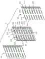
图1是本发明背板连接器组件在一种实施方式中的立体示意图。FIG. 1 is a schematic perspective view of a backplane connector assembly in an embodiment of the present invention.
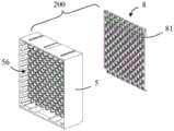
图2是图1的部分立体分解图,其中第一背板连接器和第二背板连接器相互分离。FIG. 2 is a partially exploded perspective view of FIG. 1 , wherein the first backplane connector and the second backplane connector are separated from each other.
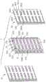
图3是图2进一步的立体分解图,其中第一背板连接器与第一电路板相互分离,第二背板连接器与第二电路板相互分离。FIG. 3 is a further perspective exploded view of FIG. 2 , wherein the first backplane connector is separated from the first circuit board, and the second backplane connector is separated from the second circuit board.
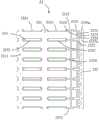
图4是图3中第一背板连接器的俯视图。FIG. 4 is a top view of the first backplane connector in FIG. 3 .
图5是图3中第一背板连接器的仰视图。FIG. 5 is a bottom view of the first backplane connector in FIG. 3 .
图6是图3中第一背板连接器的部分立体分解图。FIG. 6 is a partially exploded perspective view of the first backplane connector in FIG. 3 .
图7是图6另一角度的部分立体分解图。FIG. 7 is a partially exploded perspective view of FIG. 6 from another angle.
图8是去除图6中第一固持块后进一步的立体分解图。Fig. 8 is a further perspective exploded view after removing the first holding block in Fig. 6 .
图9是图8的俯视图。FIG. 9 is a top view of FIG. 8 .
图10是图8的仰视图。FIG. 10 is a bottom view of FIG. 8 .
图11是一个第一端子模组的立体示意图。Fig. 11 is a schematic perspective view of a first terminal module.
图12是图11另一角度的立体示意图。FIG. 12 is a schematic perspective view of another angle of FIG. 11 .
图13是图11的主视图。Fig. 13 is a front view of Fig. 11 .
图14是图11的部分立体分解图。FIG. 14 is a partially exploded perspective view of FIG. 11 .
图15是图14另一角度的部分立体分解图。Fig. 15 is a partially exploded perspective view of Fig. 14 from another angle.
图16是图14中第一金属屏蔽片的主视图。FIG. 16 is a front view of the first metal shielding sheet in FIG. 14 .
图17是图14中第二金属屏蔽片的主视图。FIG. 17 is a front view of the second metal shielding sheet in FIG. 14 .
图18是图14中绝缘支架与第一导电端子分离时的主视图。FIG. 18 is a front view of the insulating bracket in FIG. 14 when it is separated from the first conductive terminal.
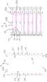
图19是沿图4中B-B线的剖面示意图。Fig. 19 is a schematic cross-sectional view along line B-B in Fig. 4 .
图20是图19中画框部分D的局部放大图。FIG. 20 is a partially enlarged view of a frame portion D in FIG. 19. FIG.
图21是沿图4中C-C线的剖面示意图。Fig. 21 is a schematic cross-sectional view along line C-C in Fig. 4 .
图22是图21中画框部分E的局部放大图。Fig. 22 is a partial enlarged view of the frame part E in Fig. 21 .
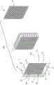
图23是第二背板连接器的部分立体分解图。FIG. 23 is a partially exploded perspective view of the second backplane connector.
图24是图23另一角度的部分立体分解图。Fig. 24 is a partially exploded perspective view of Fig. 23 from another angle.
图25是图23进一步的立体分解图。FIG. 25 is a further perspective exploded view of FIG. 23 .
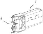
图26是金属屏蔽围绕件与第二端子模组组装后相互位置关系的立体示意图。Fig. 26 is a schematic perspective view of the mutual positional relationship between the metal shielding surrounding member and the second terminal module after assembly.
图27是图26另一角度的立体示意图。FIG. 27 is a schematic perspective view of another angle of FIG. 26 .
图28是图26的立体分解图。FIG. 28 is an exploded perspective view of FIG. 26 .
图29是图28另一角度的立体分解图。Fig. 29 is an exploded perspective view of Fig. 28 from another angle.
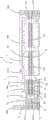
图30是沿图1中A-A线的剖面示意图。Fig. 30 is a schematic cross-sectional view along line A-A in Fig. 1 .
图31是图30中画框部分F的局部放大图。FIG. 31 is a partial enlarged view of the frame portion F in FIG. 30. FIG.
具体实施方式Detailed ways
下面将结合附图详细地对本发明示例性具体实施方式进行说明。如果存在若干具体实施方式,在不冲突的情况下,这些实施方式中的特征可以相互组合。当描述涉及附图时,除非另有说明,不同附图中相同的数字表示相同或相似的要素。以下示例性具体实施方式中所描述的内容并不代表与本发明相一致的所有实施方式;相反,它们仅是与本发明的权利要求书中所记载的、与本发明的一些方面相一致的装置、产品和/或方法的例子。Exemplary embodiments of the present invention will be described in detail below with reference to the accompanying drawings. If there are several specific embodiments, the features of these embodiments can be combined with each other under the condition of no conflict. When the description refers to the drawings, unless otherwise stated, the same numerals in different drawings identify the same or similar elements. What is described in the following exemplary embodiments does not represent all implementations consistent with the invention; rather, they are only consistent with some aspects of the invention as recited in the claims of the invention Examples of devices, products and/or methods.
在本发明中使用的术语是仅仅出于描述具体实施方式的目的,而非旨在限制本发明的保护范围。在本发明的说明书和权利要求书中所使用的单数形式的“一种”、“所述”或“该”也旨在包括多数形式,除非上下文清楚地表示其他含义。The terminology used in the present invention is only for the purpose of describing specific embodiments, and is not intended to limit the protection scope of the present invention. As used in the description and claims of the present invention, the singular forms "a", "said" or "the" are also intended to include the plural forms unless the context clearly dictates otherwise.
应当理解,本发明的说明书以及权利要求书中所使用的,例如“第一”、“第二”以及类似的词语,并不表示任何顺序、数量或者重要性,而只是用来区分特征的命名。同样,“一个”或者“一”等类似词语也不表示数量限制,而是表示存在至少一个。除非另行指出,本发明中出现的“前”、“后”、“上”、“下”等类似词语只是为了便于说明,而并非限于某一特定位置或者一种空间定向。“包括”或者“包含”等类似词语是一种开放式的表述方式,意指出现在“包括”或者“包含”前面的元件涵盖出现在“包括”或者“包含”后面的元件及其等同物,这并不排除出现在“包括”或者“包含”前面的元件还可以包含其他元件。本发明中如果出现“若干”,其含义是指两个以及两个以上。It should be understood that words such as "first", "second" and similar words used in the description and claims of the present invention do not indicate any order, quantity or importance, but are only used to distinguish the nomenclature of features . Likewise, words like "a" or "one" do not denote a limitation in quantity, but indicate that there is at least one. Unless otherwise indicated, words such as "front", "rear", "upper" and "lower" appearing in the present invention are for convenience of description only, and are not limited to a specific position or a spatial orientation. "Includes" or "comprising" and other similar words are an open-ended expression, meaning that the elements appearing before "comprising" or "comprising" cover the elements appearing after "comprising" or "comprising" and their equivalents, This does not exclude that elements appearing before "comprising" or "comprising" may also contain other elements. If "several" appears in the present invention, it means two or more.
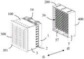
请参照图1及图2所示,本发明图示的实施方式揭示了一种背板连接器组件,所述背板连接器组件包括第一背板连接器100、与所述第一背板连接器100相配合的第二背板连接器200、与所述第一背板连接器100安装在一起的第一电路板300以及与所述第二背板连接器200安装在一起的第二电路板400。在本发明图示的实施方式中,所述第一背板连接器100与所述第二背板连接器200沿着对接方向插接,以实现信号传输。在本发明图示的实施方式中,所述对接方向为前后方向;所述第一电路板300平行于所述第二电路板400。Please refer to FIG. 1 and FIG. 2, the illustrated embodiment of the present invention discloses a backplane connector assembly, the backplane connector assembly includes a
请参照图2及图3所示,所述第一背板连接器100包括第一壳体1、安装壳体3、安装于所述第一壳体1和所述安装壳体3中的若干第一端子模组2、以及固持在所述若干第一端子模组2的后端的第一固持块4。Please refer to FIG. 2 and FIG. 3, the
请参照图4至图10所示,所述第一壳体1由绝缘材料制成,所述第一壳体1包括第一本体部11、自所述第一本体部11的一端(例如上端)向后延伸的第一壁部12以及自所述第一本体部11的另一相对端(例如下端)向后延伸的第二壁部13。所述第一本体部11设有对接面111以及贯穿所述对接面111的若干第一端子收容槽112。在本发明图示的实施方式中,所述第一端子收容槽112沿上下方向排列成多排,其中相邻的两排第一端子收容槽112沿左右方向错开布置,即相邻的两排第一端子收容槽112中对应位置处的第一端子收容槽112沿上下方向不对齐。4 to 10, the
所述第一壁部12设有若干第一插槽121以及与所述第一插槽121相连通的第一锁扣槽122。所述第二壁部13设有若干第二插槽131以及与所述第二插槽131相连通的第二锁扣槽132。所述第一锁扣槽122向上贯穿所述第一壁部12,所述第二锁扣槽132向下贯穿所述第二壁部13。所述第一锁扣槽122和所述第二锁扣槽132用以锁扣所述第一端子模组2的前端,以防止所述第一端子模组2脱离所述第一壳体1。沿上下方向相互对齐的所述第一插槽121和所述第二插槽131形成一个安装插槽120,用以收容对应的第一端子模组2。The
此外,请参照图8至图10所示,所述第一壳体1还设有分别自所述第一壁部12以及所述第二壁部13向前延伸且凸出所述对接面111的若干定位凸起14。所述定位凸起14设有位于所述定位凸起14的末端的导引斜面141,便于将所述第一背板连接器100插入所述第二背板连接器200中。In addition, please refer to FIG. 8 to FIG. 10 , the
在本发明图示的实施方式中,所述第一壳体1与所述安装壳体3沿前后方向布置,其中所述第一壳体1位于所述第一背板连接器100的前端,所述安装壳体3位于所述第一背板连接器100的后端。所述第一壳体1与所述安装壳体3分开设置,但二者在组装后相互靠近,以提升结构强度。In the illustrated embodiment of the present invention, the
请参照图7及图8所示,具体地,所述安装壳体3由绝缘材料制成且大致呈长方体状。所述安装壳体3包括靠近所述第一壳体1的第一端面31、与所述第一端面31相对的第一安装面32、沿前后方向贯穿所述第一端面31和所述第一安装面32的若干安装收容槽30。所述安装收容槽30与所述安装插槽120沿前后方向对齐,以共同收容对应的第一端子模组2。Please refer to FIG. 7 and FIG. 8 , specifically, the
所述安装壳体3还设有第三壁部33以及与所述第三壁部33相对的第四壁部34。所述第三壁部33与所述第一壁部12前后对应,所述第四壁部34与所述第二壁部13前后对应。所述第三壁部33设有与安装收容槽30相连通的第三锁扣槽331(请参照图4及图7所示),所述第四壁部34设有与安装收容槽30相连通的第四锁扣槽341(请参照图5所示)。所述第三锁扣槽331向上贯穿所述第三壁部33,所述第四锁扣槽341向下贯穿所述第四壁部34。所述第三锁扣槽331和所述第四锁扣槽341用以锁扣所述第一端子模组2的后端,以防止所述第一端子模组2脱离所述安装壳体3。The
请参照图3和图6所示,此外,所述安装壳体3还设有自所述第一安装面32向所述第一端面31的方向凹陷而成的第一安装空间35以及向后凸出所述第一安装面32的若干第一定位凸起36。所述第一安装空间35用以安装所述第一固持块4。所述第一定位凸起36用以插入第一电路板300的定位孔301中,以实现安装定位。Please refer to FIG. 3 and FIG. 6, in addition, the
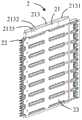
请参照图11至图15所示,所述第一端子模组2包括绝缘支架21、固定于所述绝缘支架21的若干第一导电端子22、固定在所述绝缘支架21的一侧的第一金属屏蔽片23以及固定在所述绝缘支架21的另一相对侧的第二金属屏蔽片24。11 to 15, the first
请参照图14、图15及图18所示,所述绝缘支架21大致呈框体状,所述绝缘支架21包括第一后壁211、与所述第一后壁211相对的第一前壁212、连接所述第一后壁211的一端与所述第一前壁212的一端的第一顶壁213、连接所述第一后壁211的另一端与所述第一前壁212的另一端的第一底壁214、以及连接所述第一顶壁213和所述第一底壁214的加强壁215。所述加强壁215能够对框体起到加强结构强度的作用。在本发明图示的实施方式中,所述加强壁215在前后方向上位于所述第一前壁212和所述第一后壁211之间,且所述加强壁215、所述第一前壁212和所述第一后壁211三者相互平行。所述绝缘支架21包括位于所述第一前壁212和所述加强壁215之间的第一镂空部217以及位于所述加强壁215和所述第一后壁211之间的第二镂空部218。Please refer to Fig. 14, Fig. 15 and Fig. 18, the insulating
所述第一顶壁213设有卡持于所述第一锁扣槽122内的第一锁扣凸起2131以及卡持于所述第三锁扣槽331内的第三锁扣凸起2132。所述第一底壁214设有卡持于所述第二锁扣槽132内的第二锁扣凸起2141。在本发明图示的实施方式中,所述第一锁扣凸起2131和所述第二锁扣凸起2141均为非弹性凸起,所述第三锁扣凸起2132为弹性凸起。在本发明图示的实施方式中,所述第一顶壁213设有锁扣弹臂2133,所述第三锁扣凸起2132设置于所述锁扣弹臂2133。具体地,所述锁扣弹臂2133为由后向前延伸的悬臂,所述第三锁扣凸起2132设置于所述锁扣弹臂2133的自由端。所述第一锁扣凸起2131与所述第三锁扣凸起2132的倾斜方向相反,例如所述第一锁扣凸起2131向左倾斜,所述第三锁扣凸起2132向右倾斜。请参照图13所示,在本发明图示的实施方式中,一些第一端子模组2的第一底壁214还设有卡持于所述第四锁扣槽341内的第四锁扣凸起2142。The first
请参照图14及图15所示,所述绝缘支架21还设有用以固定和定位所述第一金属屏蔽片23以及所述第二金属屏蔽片24的若干凸柱216。在本发明图示的实施方式中,所述凸柱216大致呈圆柱状。在本发明图示的实施方式中,所述凸柱216包括设置于所述第一后壁211的一侧的若干第一凸柱2161、设置于所述第一后壁211的另一侧的若干第二凸柱2162、设置于所述第一前壁212的一侧的若干第三凸柱2163、以及设置于所述第一前壁212的另一侧的若干第四凸柱2164。所述第一凸柱2161和所述第三凸柱2163位于所述绝缘支架21的同一侧,所述第二凸柱2162和所述第四凸柱2164位于所述绝缘支架21的同一侧。由于所述第一金属屏蔽片23以及所述第二金属屏蔽片24分别位于所述绝缘支架21的两侧。Please refer to FIG. 14 and FIG. 15 , the insulating
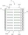
请参照图14、图15及图18所示,从结构上看,每一组第一导电端子22包括第一对接部221、第一尾部222以及连接所述第一对接部221与所述第一尾部222的第一连接部223。所述第一连接部223固定于所述绝缘支架21,且局部暴露在所述第一镂空部217以及所述第二镂空部218中,以调节阻抗。所述第一对接部221向前延伸凸出所述绝缘支架21,用以与第二背板连接器200对接。所述第一尾部222向后延伸凸出所述绝缘支架21,用以安装于第一电路板300。在本发明的一种实施方式中,所述第一固持块4由电镀塑胶或者导电塑胶制成,以提高屏蔽效果。请结合图3及图6所示,所述第一固持块4设有若干第一定位穿孔41,所述第一尾部222延伸穿过所述第一定位穿孔41以安装于第一电路板300。如此设置,有利于保证各个第一尾部222之间的距离,从而便于将所述第一尾部222安装于第一电路板300。在本发明图示的实施方式中,第一导电端子22呈直条状,且沿前后方向延伸。这种结构的第一导电端子22设计相对简单,且易于制造。Please refer to FIG. 14, FIG. 15 and FIG. 18, from a structural point of view, each group of first
从功能上看,每一组第一导电端子22包括若干第一接地端子G1、若干第二接地端子G2以及若干第一信号端子S1。在本发明图示的实施方式中,相邻的两个第一信号端子S1组成一对第一差分信号端子,且每一对第一差分信号端子位于一个第一接地端子G1与一个第二接地端子G2之间,即每一组第一导电端子22呈G1-S1-S1-G2的排列方式,这种排列方式有利于提高信号传输的质量。所述第一差分信号端子为窄边耦合或者宽边耦合。所述第一接地端子G1与所述第二接地端子G2的宽度(例如左右方向上的间距)大于它们之间的第一信号端子S1的宽度,从而有利于增加屏蔽面积,改善屏蔽效果。From a functional point of view, each group of first
在本发明图示的实施方式中,所述第一导电端子22的第一连接部223嵌入成型于所述绝缘支架21。所述第一信号端子S1的第一连接部223设有埋入所述绝缘支架21中的收窄部2230,以调节所述第一信号端子S1的阻抗,实现阻抗匹配。在本发明图示的实施方式中,所述第一导电端子22的第一连接部223较长(所述第一信号端子S1的第一连接部223又细又长),本发明通过设置加强壁215,并将所述第一导电端子22的第一连接部223嵌入成型于所述加强壁215,提高了第一导电端子22的强度,使第一导电端子22不容易发生弯曲。在本发明图示的实施方式中,所述第一信号端子S1的第一对接部221大致呈针状,所述第一接地端子G1与所述第二接地端子G2的第一对接部221大致呈扁平状。所述第一信号端子S1的第一对接部221与所述第一导电端子22的第一连接部223均共面,即位于第一平面(例如竖直面)内。需要说明的是,本发明中所使用的技术术语“共面”旨在表明相关元件之间是实质平齐的,包括由于制造公差所造成的不完全共面的情形。然而,在本发明图示的实施方式中,所述第一接地端子G1的第一连接部223设有与该第一接地端子G1的第一对接部221相连的第一扭转部2231,从而使所述第一接地端子G1的第一对接部221位于垂直于所述第一平面的第二平面(例如水平面)内。所述第二接地端子G2的第一连接部223设有与该第二接地端子G2的第一对接部221相连的第二扭转部2232,从而使所述第二接地端子G2的第一对接部221也位于垂直于所述第一平面的第二平面(例如水平面)内。所述第一接地端子G1的第一对接部221与所述第二接地端子G2的第一对接部221相互平行。In the illustrated embodiment of the present invention, the first connecting
请参照图19及图20所示,在本发明图示的实施方式中,所述第一接地端子G1的第一对接部221与第一连接部223均设有第一宽面221a以及垂直于所述第一宽面221a的第一窄面221b。所述第二接地端子G2的第一对接部221与第一连接部223均设有第二宽面221c以及垂直于所述第二宽面221c的第二窄面221d。每一对第一差分信号端子的第一连接部223位于该第一连接部223两侧的第一接地端子G1的第一窄面221b以及第二接地端子G2的第二窄面221d之间(如图20所示)。每一对第一差分信号端子的第一对接部221位于该第一对接部221两侧的第一接地端子G1的第一宽面221a以及第二接地端子G2的第二宽面221c之间(如图22所示)。在本发明图示的实施方式中,所述第一宽面221a与所述第二宽面221c的宽度大于所述第一信号端子S1的第一对接部221的宽度,从而能够给所述第一信号端子S1的第一对接部221提供更好的屏蔽。Please refer to FIG. 19 and FIG. 20 , in the illustrated embodiment of the present invention, the
在本发明图示的实施方式中,所述第一金属屏蔽片23与所述第二金属屏蔽片24对称设置在所述绝缘支架21的两侧。请参照图14至图16所示,所述第一金属屏蔽片23包括第一主体部231以及自所述第一主体部231延伸的第一延伸部232。所述第一主体部231位于所述第一导电端子22的第一连接部223的一侧,所述第一延伸部232位于所述第一导电端子22的第一对接部221的一侧。在本发明图示的实施方式中,所述第一延伸部232与所述第一主体部231位于不同的平面内,其中所述第一延伸部232比所述第一主体部231更远离所述第二金属屏蔽片24。所述第一主体部231设有与若干第一凸柱2161相配合的若干第一安装孔2311以及与若干第三凸柱2163相配合的若干第三安装孔2310。通过焊接将第一凸柱2161固定且定位于第一安装孔2311中,将第三凸柱2163固定且定位于第三安装孔2310中,从而实现所述第一金属屏蔽片23与所述绝缘支架21的固定与定位。所述第一主体部231设有若干凸肋233,所述凸肋233包括向所述第一接地端子G1凸出的第一凸肋2331以及向所述第二接地端子G2凸出的第二凸肋2332。所述第一凸肋2331沿所述第一接地端子G1的第一连接部223的延伸方向设置。所述第二凸肋2332沿所述第二接地端子G2的第一连接部223的延伸方向设置。在本发明图示的实施方式中,所述第一凸肋2331与所述第二凸肋2332是由冲压所述第一主体部231而形成。所述第一凸肋2331与所述第二凸肋2332向所述第二金属屏蔽片24的方向凸出。所述第一凸肋2331与所述第二凸肋2332沿所述第一接地端子G1与所述第二接地端子G2的第一连接部223的延伸方向不连续地设置,实现多点接触,以提高第一金属屏蔽片23与第一接地端子G1以及第二接地端子G2的接触可靠性。在本发明图示的实施方式中,请参照图20所示,所述第一凸肋2331的壁厚、所述第二凸肋2332的壁厚以及所述第一主体部231位于所述第一凸肋2331与所述第二凸肋2332之间的部分的壁厚相同。此外,所述第一主体部231的上下边缘还分别设有与所述绝缘支架21相配合的若干第一定位缺口2312。In the illustrated embodiment of the present invention, the first
所述第一延伸部232设有向所述第一接地端子G1的第一对接部221凸出的第一凸起2321、向所述第二接地端子G2的第一对接部221凸出的第二凸起2322、以及位于相邻的第一凸起2321与第二凸起2322之间的第一弹片2323。所述第一弹片2323向所述第一主体部231的方向延伸,所述第一弹片2323设有弧形对接部2324。在本发明图示的实施方式中,所述第一延伸部232还设有位于所述第一弹片2323的两端的两个第一凸片2325,所述第一凸片2325与所述第一弹片2323的延伸方向相反,所述第一凸片2325向外凸出以与相邻的第一端子模组2相接触,以提高屏蔽效果。在本发明图示的实施方式中,请参照图22所示,所述第一凸起2321的壁厚、所述第二凸起2322的壁厚以及所述第一延伸部232位于所述第一凸起2321与所述第二凸起2322之间的部分的壁厚相同。此外,所述第一延伸部232还设有第一抵接块2326a以及第二抵接块2327a。对应于一个第一接地端子G1和一个第二接地端子G2,所述第一抵接块2326a与所述第二抵接块2327a可以为一个或者两个,且用以在竖直方向上抵接或者夹持相应的第一接地端子G1与第二接地端子G2的对接部221,以实现限位。The
类似地,请参照图14、图15及图17所示,所述第二金属屏蔽片24包括第二主体部241以及自所述第二主体部241延伸的第二延伸部242。所述第二主体部241位于所述第一导电端子22的第一连接部223的另一相对侧,所述第二延伸部242位于所述第一导电端子22的第一对接部221的另一相对侧。在本发明图示的实施方式中,所述第二延伸部242与所述第二主体部241位于不同的平面内,其中所述第二延伸部242比所述第二主体部241更远离所述第一金属屏蔽片23。所述第二主体部241设有与若干第二凸柱2162相配合的若干第二安装孔2411以及与若干第四凸柱2164相配合的若干第四安装孔2410。通过焊接将第二凸柱2162固定且定位于第二安装孔2411中,将第四凸柱2164固定且定位于第四安装孔2410中,从而实现所述第二金属屏蔽片24与所述绝缘支架21的固定与定位。所述第二主体部241设有若干凸肋243,所述凸肋243包括向所述第一接地端子G1凸出的第三凸肋2431以及向所述第二接地端子G2凸出的第四凸肋2432。所述第三凸肋2431沿所述第一接地端子G1的第一连接部223的延伸方向设置。所述第四凸肋2432沿所述第二接地端子G2的第一连接部223的延伸方向设置。在本发明图示的实施方式中,所述第三凸肋2431与所述第四凸肋2432是由冲压所述第二主体部241而形成。所述第三凸肋2431与所述第四凸肋2432向所述第一金属屏蔽片23的方向凸出。所述第三凸肋2431与所述第四凸肋2432沿所述第一接地端子G1与所述第二接地端子G2的第一连接部223的延伸方向不连续地设置,实现多点接触,以提高第二金属屏蔽片24与第一接地端子G1以及第二接地端子G2的接触可靠性。在本发明图示的实施方式中,所述第三凸肋2431的壁厚、所述第四凸肋2432的壁厚以及所述第二主体部241位于所述第三凸肋2431与所述第四凸肋2432之间的部分的壁厚相同。在本发明的一种实施方式中,在所述凸肋233以及所述凸肋243的表面上进行焊接,用以将所述凸肋233以及所述凸肋243与所述第一接地端子G1以及所述第二接地端子G2相焊接。例如,在所述第一凸肋2331、所述第二凸肋2332、所述第三凸肋2431以及所述第四凸肋2432的表面上进行焊接,用以将所述第一凸肋2331、所述第二凸肋2332、所述第三凸肋2431以及所述第四凸肋2432与所述第一接地端子G1以及所述第二接地端子G2相焊接,其中焊接方式为点焊、激光焊及超声波焊中的至少一种。此外,所述第二主体部241的上下边缘还分别设有与所述绝缘支架21相配合的若干第二定位缺口2412。Similarly, please refer to FIG. 14 , FIG. 15 and FIG. 17 , the second
所述第二延伸部242设有向所述第一接地端子G1的第一对接部221凸出的第三凸起2421、向所述第二接地端子G2的第一对接部221凸出的第四凸起2422、以及位于相邻的第三凸起2421与第四凸起2422之间的第二弹片2423。所述第二弹片2423向所述第二主体部241的方向延伸,所述第二弹片2423设有弧形对接部2424。在本发明图示的实施方式中,所述第二延伸部242还设有位于所述第二弹片2423的两端的两个第二凸片2425,所述第二凸片2425与所述第二弹片2423的延伸方向相反,所述第二凸片2425向外凸出以与相邻的第一端子模组2相接触,以提高屏蔽效果。在本发明图示的实施方式中,所述第三凸起2421的壁厚、所述第四凸起2422的壁厚以及所述第二延伸部242位于所述第三凸起2421与所述第四凸起2422之间的部分的壁厚相同。此外,所述第二延伸部242还设有第三抵接块2426a以及第四抵接块2427a,对应于一个第一接地端子G1和一个第二接地端子G2,所述第三抵接块2426a与第四抵接块2427a可以为一个或者两个,且用以在竖直方向上抵接或者夹持相应的第一接地端子G1与第二接地端子G2的对接部221,以实现限位。The
请参照图20所示,在所述第一导电端子22的第一连接部223的长度上,所述第一金属屏蔽片23的第一凸肋2331以及所述第二金属屏蔽片24的第三凸肋2431分别与第一接地端子G1的第一连接部223的两相对侧面接触,从而在每一对第一差分信号端子的第一连接部223的外周形成了环绕的屏蔽腔26。在本发明图示的实施方式中,所述第一凸肋2331与所述第三凸肋2431分别与所述第一接地端子G1的第一连接部223的第一宽面221a相接触,所述第二凸肋2332与所述第四凸肋2432分别与所述第二接地端子G2的第一连接部223的第二宽面221c相接触。在本发明图示的实施方式中,所述屏蔽腔26是由所述第一主体部231、所述第二主体部241、所述第一接地端子G1以及所述第二接地端子G2共同形成。所述第一接地端子G1的第一连接部223设有延伸入所述屏蔽腔26中的第一凸片部2234,所述第二接地端子G2的第一连接部223设有延伸入所述屏蔽腔26中的第二凸片部2235,所述第一差分信号端子的第一连接部223位于所述第一凸片部2234与所述第二凸片部2235之间。所述屏蔽腔26为多个且沿着每一组所述第一导电端子22的排布方向连续设置,其中相邻的两个屏蔽腔26共用一个第一接地端子G1或者共用一个第二接地端子G2。且该共用的第一接地端子G1一部分凸伸入一个屏蔽腔26,该共用的第一接地端子G1另一部分凸伸入另一个屏蔽腔26。Please refer to FIG. 20 , on the length of the first connecting
请参照图22所示,在所述第一导电端子22的第一对接部221的长度上,所述第一金属屏蔽片23的第一凸起2321与所述第三凸起2421分别与所述第一接地端子G1的第一对接部221的两相对侧面相接触,所述第二凸起2322与所述第四凸起2422分别与所述第二接地端子G2的第一对接部221的两相对侧面相接触。在本发明图示的实施方式中,所述第一金属屏蔽片23的第一凸起2321与所述第三凸起2421分别与所述第一接地端子G1的第一对接部221的第一窄面221b相接触,所述第二凸起2322与所述第四凸起2422分别与所述第二接地端子G2的第一对接部221的第二窄面221d相接触。所述第一延伸部232、所述第二延伸部242、所述第一接地端子G1以及所述第二接地端子G2围成收容所述第一差分信号端子的第一对接部221的屏蔽腔体27。所述第一弹片2323与所述第二弹片2423延伸入所述屏蔽腔体27内。所述屏蔽腔体27沿着每一组所述第一导电端子22的层叠方向连续设置,其中相邻的两个屏蔽腔体27共用一个第一接地端子G1或者共用一个第二接地端子G2。该共用的第一接地端子G1的第一对接部221的一个第一宽面221a暴露于屏蔽腔体27,该共用的第一接地端子G1的第一对接部221的另一个第一宽面221a暴露于相邻的屏蔽腔体27。类似地,该共用的第二接地端子G2的第一对接部221的一个第二宽面221c暴露于屏蔽腔体27,该共用的第二接地端子G2的第一对接部221的另一个第二宽面221c暴露于相邻的屏蔽腔体27。Please refer to FIG. 22, on the length of the first abutting
在本发明图示的实施方式中,所述第一背板连接器100的第一端子模组2有多个,且相邻的两个第一端子模组2的端子布置是错开的。相应地,相邻的两个第一端子模组2的相同位置处的屏蔽腔26相互错开;相邻的两个第一端子模组2的相同位置处的屏蔽腔体27相互错开。In the illustrated embodiment of the present invention, there are multiple first
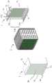
请参照图23至图25所示,所述第二背板连接器200包括第二壳体5、安装于所述第二壳体5内的若干第二端子模组6、固定于所述第二壳体5且位于所述第二端子模组6外的金属屏蔽围绕件7以及安装于所述第二壳体5的第二固持块8。Please refer to FIG. 23 to FIG. 25, the
所述第二壳体5是由绝缘材料制成,所述第二壳体5包括基部50以及自所述基部50向后延伸的、围绕的壁部55。所述壁部55包括第一侧壁51、与所述第一侧壁51相对设置的第二侧壁52、连接所述第一侧壁51的一侧和所述第二侧壁52的一侧的第三侧壁53、以及连接所述第一侧壁51的另一侧和所述第二侧壁52的另一侧的第四侧壁54。所述基部50与所述壁部55共同形成一个用以收容部分所述第一背板连接器100的收容空间56。The
所述第一侧壁51和所述第二侧壁52分别设有与所述第一背板连接器100的定位凸起14相配合的定位凹槽57。此外,所述基部50还设有第二安装面501以及自所述第二安装面501向后凹陷而成的第二安装空间502,所述第二安装空间502用以安装所述第二固持块8。The
在本发明图示的实施方式中,所述第二壳体5还设有自所述基部50一体延伸且间隔设置的若干绝缘凸起58。若干绝缘凸起58向后延伸入所述收容空间56内。若干绝缘凸起58沿左右方向排列为多排,且相邻两排中的绝缘凸起58错位布置,即相邻两排中位于同一位置处的绝缘凸起58沿左右方向不对齐。每一个绝缘凸起58设有至少部分收容所述第二端子模组6的收容孔581。In the illustrated embodiment of the present invention, the
请参照图26至图29所示,在本发明图示的实施方式中,所述金属屏蔽围绕件7是由一块金属板冲压、弯折、铆接而成,所述金属屏蔽围绕件7包括筒体部71、自所述筒体部71向前延伸的安装部72以及自所述安装部72向前延伸的若干安装脚73。所述筒体部71包括依次连接的第一侧壁711、第二侧壁712、第三侧壁713以及第四侧壁714,其中所述第一侧壁711与所述第三侧壁713相对,所述第二侧壁712与所述第四侧壁714相对,以围成全包式屏蔽腔体。当然,在其它实施方式中,所述屏蔽腔体也可以是非全包式,例如所述筒体部71包括依次连接的第二侧壁712、第三侧壁713以及第四侧壁714,使所述筒体部71大致呈U形。在本发明图示的实施方式中,所述第一侧壁711与所述第三侧壁713的面积大于所述第二侧壁712与所述第四侧壁714的面积。所述第一侧壁711、第二侧壁712、第三侧壁713以及第四侧壁714的末端均设有向内弯折的偏转部715,这些偏转部715各自独立,以便于各自独立弯折,避免相互干扰。通过设置所述偏转部715,能够在金属屏蔽围绕件7的末端形成一个收缩口,易于将偏转部715导引插入第一背板连接器100中。Please refer to Fig. 26 to Fig. 29, in the illustrated embodiment of the present invention, the metal
在本发明图示的实施方式中,所述安装部72大致呈U形,所述安装部72包括连接部720、自所述连接部720的一侧弯折的第一弯折部721以及自所述连接部720的另一相对侧弯折的第二弯折部722。所述连接部720与所述第三侧壁713共面。所述第一弯折部721与所述第二侧壁712位于同一侧,且所述第一弯折部721向外(例如向上)凸出所述第二侧壁712。所述第二弯折部722与所述第四侧壁714位于同一侧,且所述第二弯折部722向外(例如向下)凸出所述第四侧壁714。所述安装部72还包括位于所述连接部720的底部扣持部726。在本发明图示的实施方式中,当金属屏蔽围绕件7未安装于绝缘凸起58时,所述扣持部726与所述连接部720位于同一平面内;当金属屏蔽围绕件7安装于绝缘凸起58后,向内弯折(即向所述壁部55的方向)所述扣持部726,使所述扣持部726垂直于所述连接部720。所述扣持部726位于所述连接部720的前端中部的位置。In the illustrated embodiment of the present invention, the
请参照图27至图29所示,每一第二端子模组6包括绝缘块61以及固定于所述绝缘块61的若干第二导电端子62。在本发明的一种实施方式中,所述第二导电端子62嵌入成型在所述绝缘块61中。所述第二导电端子62包括第一信号端子621以及第二信号端子622。在本发明的一种实施方式中,从功能上看,就每一个第二端子模组6而言,所述第一信号端子621与所述第二信号端子622形成一组第二差分信号端子。在本发明图示的实施方式中,所述第一信号端子621与所述第二信号端子622沿所述绝缘块61的中轴线对称设置。Referring to FIGS. 27 to 29 , each
从结构上看,所述第二导电端子62包括接触臂624、第二尾部625以及连接所述接触臂624与所述第二尾部625的第二连接部626。所述第二连接部626固定于所述绝缘块61。所述接触臂624向后延伸凸出所述绝缘块61,用以与第一背板连接器100电性连接。所述第二尾部625向前延伸凸出所述绝缘块61,用以与第二电路板400电性连接。在本发明的一种实施方式中,所述第二固持块8由电镀塑胶或者导电塑胶制成,以提高屏蔽效果。请结合图24、图30以及图31所示,所述第二固持块8设有若干第二定位穿孔81,所述第二尾部625以及所述安装脚73延伸穿过所述第二定位穿孔81以安装于第二电路板400。如此设置,有利于保证各个第二尾部625以及安装脚73之间的距离,从而便于将所述第二尾部625以及安装脚73安装于第二电路板400。在本发明图示的实施方式中,所述第二导电端子62大致呈直条状,且沿前后方向延伸。From a structural point of view, the second
组装时,首先,将若干金属屏蔽围绕件7从后向前套接于绝缘凸起58上,使筒体部71包裹在绝缘凸起58的四周;将若干第二端子模组6从前向后插入对应的收容孔581中。然后,将扣持部726向内弯折,使所述扣持部726与绝缘块61相抵接。如此设置,一方面能够防止金属屏蔽围绕件7向后脱离绝缘凸起58,另一方面能够防止第二端子模组6向前脱离第二壳体5。最后,将第二固持块8安装于第二安装空间502中。金属屏蔽围绕件7的安装脚73和第二导电端子62的第二尾部625穿过第二固持块8的第二定位穿孔81,以与第二电路板400电性连接。When assembling, firstly, several metal
当所述第一背板连接器100与所述第二背板连接器200相配合时,所述第一背板连接器100的第一壳体1插入所述第二背板连接器200的第二壳体5的收容空间56中,所述第二背板连接器200的第二端子模组6的筒体部71在偏转部715的导引下插入所述第一背板连接器100的屏蔽腔体27中。所述第一背板连接器100的第一差分信号端子与所述第二背板连接器200的第二差分信号端子相对接,以实现电性连接。When the
以上实施方式仅用于说明本发明而并非限制本发明所描述的技术方案,对本发明的理解应该以所属技术领域的技术人员为基础,尽管本说明书参照上述的实施方式对本发明已进行了详细的说明,但是,所属技术领域的技术人员仍然可以对本发明进行修改或者等同替换,而一切不脱离本发明的精神和范围的技术方案及其改进,均应涵盖在本发明的权利要求范围内。The above embodiments are only used to illustrate the present invention rather than limit the technical solutions described in the present invention. The understanding of the present invention should be based on those skilled in the art, although this specification has described the present invention in detail with reference to the above embodiments. Note, however, those skilled in the art can still modify the present invention or replace it equivalently, and all technical solutions and improvements that do not depart from the spirit and scope of the present invention should be covered within the scope of the claims of the present invention.
Claims (12)
Priority Applications (2)
| Application Number | Priority Date | Filing Date | Title |
|---|---|---|---|
| TW110113832ATWI792271B (en) | 2020-06-19 | 2021-04-16 | Backplane connector assembly |
| US17/340,969US11637402B2 (en) | 2020-06-19 | 2021-06-07 | Backplane connector assembly |
Applications Claiming Priority (2)
| Application Number | Priority Date | Filing Date | Title |
|---|---|---|---|
| CN202010567796 | 2020-06-19 | ||
| CN2020105677964 | 2020-06-19 |
Publications (2)
| Publication Number | Publication Date |
|---|---|
| CN113823958A CN113823958A (en) | 2021-12-21 |
| CN113823958Btrue CN113823958B (en) | 2023-07-11 |
Family
ID=72438191
Family Applications (30)
| Application Number | Title | Priority Date | Filing Date |
|---|---|---|---|
| CN202021461747.4UActiveCN212849124U (en) | 2020-06-19 | 2020-07-22 | Back panel connector |
| CN202021462818.2UActiveCN212849125U (en) | 2020-06-19 | 2020-07-22 | Back panel connector |
| CN202010709127.6AActiveCN111682366B (en) | 2020-06-19 | 2020-07-22 | Backplane connector assembly |
| CN202021461673.4UActiveCN212849123U (en) | 2020-06-19 | 2020-07-22 | Back panel connector |
| CN202010709180.6AActiveCN111682367B (en) | 2020-06-19 | 2020-07-22 | Back panel connector |
| CN202021462798.9UActiveCN213151158U (en) | 2020-06-19 | 2020-07-22 | Back panel connector |
| CN202021462763.5UActiveCN213151157U (en) | 2020-06-19 | 2020-07-22 | Circuit board and backplane connector assembly |
| CN202010710463.2AActiveCN111682369B (en) | 2020-06-19 | 2020-07-22 | Back panel connector |
| CN202010710402.6AActiveCN111682368B (en) | 2020-06-19 | 2020-07-22 | Back panel connector |
| CN202021598514.9UActiveCN213151159U (en) | 2020-06-19 | 2020-08-04 | Shielding shell |
| CN202021708219.4UActiveCN212412339U (en) | 2020-06-19 | 2020-08-17 | Backplane connector assembly |
| CN202021708192.9UActiveCN212412338U (en) | 2020-06-19 | 2020-08-17 | Back panel connector |
| CN202010822431.1APendingCN111864475A (en) | 2020-06-19 | 2020-08-17 | Back panel connector |
| CN202021709484.4UActiveCN213151160U (en) | 2020-06-19 | 2020-08-17 | Back panel connector |
| CN202010823256.8AActiveCN111864477B (en) | 2020-06-19 | 2020-08-17 | Backplane Connectors |
| CN202021717656.2UActiveCN212412340U (en) | 2020-06-19 | 2020-08-17 | Back panel connector |
| CN202021709481.0UActiveCN212849126U (en) | 2020-06-19 | 2020-08-17 | Back panel connector |
| CN202010823188.5APendingCN111864476A (en) | 2020-06-19 | 2020-08-17 | backplane connector |
| CN202010823428.1AActiveCN111864478B (en) | 2020-06-19 | 2020-08-17 | Backplane Connector Assemblies |
| CN202010931721.XAActiveCN111900577B (en) | 2020-06-19 | 2020-09-07 | Back panel connector |
| CN202021934671.2UActiveCN212849127U (en) | 2020-06-19 | 2020-09-07 | Back panel connector |
| CN202021934802.7UActiveCN212849128U (en) | 2020-06-19 | 2020-09-07 | Back panel connector |
| CN202021936502.2UActiveCN213460337U (en) | 2020-06-19 | 2020-09-07 | Terminal module and backplane connector |
| CN202023230734.9UActiveCN213878626U (en) | 2020-06-19 | 2020-12-28 | Terminal module and backplane connector |
| CN202011577310.1AActiveCN112510442B (en) | 2020-06-19 | 2020-12-28 | Back panel connector |
| CN202023230791.7UActiveCN213878627U (en) | 2020-06-19 | 2020-12-28 | Terminal module and backplane connector |
| CN202023231405.6UActiveCN213878628U (en) | 2020-06-19 | 2020-12-28 | Terminal module and backplane connector |
| CN202110037249.XAActiveCN112864724B (en) | 2020-06-19 | 2021-01-12 | backplane connector |
| CN202110037232.4AActiveCN113823958B (en) | 2020-06-19 | 2021-01-12 | Backboard connector assembly |
| CN202120475647.5UActiveCN214798035U (en) | 2020-06-19 | 2021-03-04 | Back panel connector |
Family Applications Before (28)
| Application Number | Title | Priority Date | Filing Date |
|---|---|---|---|
| CN202021461747.4UActiveCN212849124U (en) | 2020-06-19 | 2020-07-22 | Back panel connector |
| CN202021462818.2UActiveCN212849125U (en) | 2020-06-19 | 2020-07-22 | Back panel connector |
| CN202010709127.6AActiveCN111682366B (en) | 2020-06-19 | 2020-07-22 | Backplane connector assembly |
| CN202021461673.4UActiveCN212849123U (en) | 2020-06-19 | 2020-07-22 | Back panel connector |
| CN202010709180.6AActiveCN111682367B (en) | 2020-06-19 | 2020-07-22 | Back panel connector |
| CN202021462798.9UActiveCN213151158U (en) | 2020-06-19 | 2020-07-22 | Back panel connector |
| CN202021462763.5UActiveCN213151157U (en) | 2020-06-19 | 2020-07-22 | Circuit board and backplane connector assembly |
| CN202010710463.2AActiveCN111682369B (en) | 2020-06-19 | 2020-07-22 | Back panel connector |
| CN202010710402.6AActiveCN111682368B (en) | 2020-06-19 | 2020-07-22 | Back panel connector |
| CN202021598514.9UActiveCN213151159U (en) | 2020-06-19 | 2020-08-04 | Shielding shell |
| CN202021708219.4UActiveCN212412339U (en) | 2020-06-19 | 2020-08-17 | Backplane connector assembly |
| CN202021708192.9UActiveCN212412338U (en) | 2020-06-19 | 2020-08-17 | Back panel connector |
| CN202010822431.1APendingCN111864475A (en) | 2020-06-19 | 2020-08-17 | Back panel connector |
| CN202021709484.4UActiveCN213151160U (en) | 2020-06-19 | 2020-08-17 | Back panel connector |
| CN202010823256.8AActiveCN111864477B (en) | 2020-06-19 | 2020-08-17 | Backplane Connectors |
| CN202021717656.2UActiveCN212412340U (en) | 2020-06-19 | 2020-08-17 | Back panel connector |
| CN202021709481.0UActiveCN212849126U (en) | 2020-06-19 | 2020-08-17 | Back panel connector |
| CN202010823188.5APendingCN111864476A (en) | 2020-06-19 | 2020-08-17 | backplane connector |
| CN202010823428.1AActiveCN111864478B (en) | 2020-06-19 | 2020-08-17 | Backplane Connector Assemblies |
| CN202010931721.XAActiveCN111900577B (en) | 2020-06-19 | 2020-09-07 | Back panel connector |
| CN202021934671.2UActiveCN212849127U (en) | 2020-06-19 | 2020-09-07 | Back panel connector |
| CN202021934802.7UActiveCN212849128U (en) | 2020-06-19 | 2020-09-07 | Back panel connector |
| CN202021936502.2UActiveCN213460337U (en) | 2020-06-19 | 2020-09-07 | Terminal module and backplane connector |
| CN202023230734.9UActiveCN213878626U (en) | 2020-06-19 | 2020-12-28 | Terminal module and backplane connector |
| CN202011577310.1AActiveCN112510442B (en) | 2020-06-19 | 2020-12-28 | Back panel connector |
| CN202023230791.7UActiveCN213878627U (en) | 2020-06-19 | 2020-12-28 | Terminal module and backplane connector |
| CN202023231405.6UActiveCN213878628U (en) | 2020-06-19 | 2020-12-28 | Terminal module and backplane connector |
| CN202110037249.XAActiveCN112864724B (en) | 2020-06-19 | 2021-01-12 | backplane connector |
Family Applications After (1)
| Application Number | Title | Priority Date | Filing Date |
|---|---|---|---|
| CN202120475647.5UActiveCN214798035U (en) | 2020-06-19 | 2021-03-04 | Back panel connector |
Country Status (3)
| Country | Link |
|---|---|
| US (24) | US11563290B2 (en) |
| CN (30) | CN212849124U (en) |
| TW (24) | TWM609292U (en) |
Families Citing this family (63)
| Publication number | Priority date | Publication date | Assignee | Title |
|---|---|---|---|---|
| WO2019139882A1 (en)* | 2018-01-09 | 2019-07-18 | Molex, Llc | High density receptacle |
| CN212849124U (en) | 2020-06-19 | 2021-03-30 | 东莞立讯技术有限公司 | Back panel connector |
| CN112652906B (en) | 2020-06-19 | 2022-12-02 | 东莞立讯技术有限公司 | Plugging module and cable connector |
| TWI792271B (en) | 2020-06-19 | 2023-02-11 | 大陸商東莞立訊技術有限公司 | Backplane connector assembly |
| USD987574S1 (en)* | 2020-06-30 | 2023-05-30 | Dongguan Luxshare Technologies Co., Ltd | Electrical connector |
| CN112636046B (en)* | 2020-11-30 | 2022-04-22 | 中航光电科技股份有限公司 | Orthogonal Connector Wafers, Orthogonal Connectors, and Connector Assemblies |
| CN112510396B (en)* | 2020-12-01 | 2025-06-27 | 温州意华接插件股份有限公司 | Terminal assembly and electrical connector |
| CN114665330B (en)* | 2020-12-22 | 2023-01-06 | 华为技术有限公司 | A connector, function board and board-level structure |
| CN112736524B (en) | 2020-12-28 | 2022-09-09 | 东莞立讯技术有限公司 | Terminal module and backplane connector |
| CN112636098A (en)* | 2020-12-28 | 2021-04-09 | 深圳市创益通技术股份有限公司 | 5G bent female frame port type high-shielding structure connector and manufacturing method thereof |
| CN112909660B (en)* | 2021-01-20 | 2022-04-22 | 中航光电科技股份有限公司 | Connector assembly |
| CN112909595B (en)* | 2021-01-20 | 2022-05-13 | 中航光电科技股份有限公司 | Shielding plate, terminal module using shielding plate and female terminal connector |
| CN112909661B (en)* | 2021-01-20 | 2023-04-18 | 中航光电科技股份有限公司 | Terminal module and connector using same |
| CN112909663B (en)* | 2021-01-20 | 2022-04-22 | 中航光电科技股份有限公司 | Shielding plate, terminal module using same and connector |
| CN113193407B (en)* | 2021-02-02 | 2022-10-25 | 中山得意电子有限公司 | Electrical connector |
| CN215645331U (en)* | 2021-02-09 | 2022-01-25 | 中航光电科技股份有限公司 | Shielding piece and bent female connector using same |
| CN114628958B (en)* | 2021-02-09 | 2024-04-16 | 中航光电科技股份有限公司 | Differential signal module and differential signal connector |
| CN113036541B (en)* | 2021-02-25 | 2023-03-31 | 中山得意电子有限公司 | Electrical module |
| CN113193398B (en)* | 2021-04-23 | 2022-03-29 | 中航光电科技股份有限公司 | A shielding contact structure, a female connector and a connector assembly |
| CN115347423B (en)* | 2021-05-13 | 2025-09-16 | 泰科电子(上海)有限公司 | Electric connector assembly |
| TWI816126B (en)* | 2021-05-17 | 2023-09-21 | 佳必琪國際股份有限公司 | Electrical connector |
| CN113488815B (en)* | 2021-08-13 | 2025-06-27 | 四川永贵科技有限公司 | Shielding plate, sheet body, female connector and connector assembly |
| CN113314895A (en)* | 2021-06-03 | 2021-08-27 | 四川永贵科技有限公司 | High-speed backplane connector and connector system |
| EP4099518A1 (en) | 2021-06-03 | 2022-12-07 | Sichuan Yonggui Science and Technology Co., Ltd | Shielding plate, terminal module, high-speed backplane connector, and connector system |
| CN215816681U (en)* | 2021-06-04 | 2022-02-11 | 华为技术有限公司 | Connector and electronic device |
| CN113437589B (en)* | 2021-07-16 | 2025-08-19 | 中航光电科技股份有限公司 | Connector with shielding shell |
| CN113571973B (en)* | 2021-07-21 | 2024-03-19 | 中航光电科技股份有限公司 | Terminal module and high-speed connector using the same |
| CN113904179B (en) | 2021-08-16 | 2023-07-11 | 东莞立讯技术有限公司 | Butt-joint terminal module, butt-joint backboard connector and backboard connector assembly |
| CN113889785B (en)* | 2021-08-16 | 2023-07-11 | 东莞立讯技术有限公司 | Terminal module and back board connector |
| JP2023028570A (en)* | 2021-08-19 | 2023-03-03 | イリソ電子工業株式会社 | Connector and connector set |
| CN113871973A (en)* | 2021-10-18 | 2021-12-31 | 武汉市格力浦电子有限公司 | High-speed connector with low crosstalk |
| CN116111402A (en)* | 2021-11-10 | 2023-05-12 | 东莞富强电子有限公司 | High-speed connector |
| CN114300914B (en)* | 2021-11-26 | 2024-06-11 | 深圳市深科达智能装备股份有限公司 | Plug-in device, system and control method |
| CN116191132A (en)* | 2021-11-26 | 2023-05-30 | 华为技术有限公司 | Receptacle Connectors, Male Connectors and Connector Assemblies |
| CN114389073B (en) | 2022-01-11 | 2023-09-19 | 东莞立讯技术有限公司 | Electrical connectors and components |
| CN114421240B (en)* | 2022-01-26 | 2024-04-30 | 成电智连(成都)科技有限公司 | Shielding element and electric connector |
| CN114421241B (en)* | 2022-01-26 | 2024-04-30 | 成电智连(成都)科技有限公司 | Electric connector and electric connector assembly |
| CN114639979B (en)* | 2022-02-18 | 2024-05-17 | 鹤山市得润电子科技有限公司 | Connector, connector module and electronic device |
| CN114498205A (en)* | 2022-03-10 | 2022-05-13 | 深圳市西点精工技术有限公司 | Back panel connector |
| CN114927894B (en) | 2022-06-10 | 2024-11-08 | 东莞立讯技术有限公司 | Electrical connector |
| CN115021033B (en)* | 2022-06-23 | 2024-05-24 | 四川华丰科技股份有限公司 | Connector with a plurality of connectors |
| CN115133354B (en)* | 2022-07-07 | 2025-08-12 | 中航光电科技股份有限公司 | Shielding structure and electric connector using same |
| CN119547280A (en)* | 2022-08-11 | 2025-02-28 | 莫列斯有限公司 | Connector assembly with U-shaped shield and ground plate |
| CN115296091B (en)* | 2022-08-29 | 2025-07-01 | 深圳市西点精工技术有限公司 | Shielding sheet, communication module and backplane connector socket |
| CN115832740A (en)* | 2022-10-31 | 2023-03-21 | 立讯精密工业股份有限公司 | electrical connector |
| CN115986501A (en)* | 2022-12-13 | 2023-04-18 | 东莞立讯技术有限公司 | Cable connectors and electrical connectors |
| TWI886523B (en)* | 2023-07-26 | 2025-06-11 | 大陸商東莞立訊技術有限公司 | Backplane connector |
| CN117199938A (en)* | 2023-08-10 | 2023-12-08 | 东莞立讯技术有限公司 | Electric connector and assembly thereof |
| CN117175259A (en)* | 2023-09-08 | 2023-12-05 | 中航光电科技股份有限公司 | Positioning buckle plate for connector and connector |
| CN119601998A (en)* | 2023-09-11 | 2025-03-11 | 东莞立讯技术有限公司 | Electrical connector and connector assembly |
| CN117317714B (en)* | 2023-09-28 | 2024-05-31 | 东莞立讯技术有限公司 | Electrical connector |
| CN119726264A (en)* | 2023-09-28 | 2025-03-28 | 中航光电科技股份有限公司 | A connector |
| CN119726263A (en)* | 2023-09-28 | 2025-03-28 | 中航光电科技股份有限公司 | A connector plug-in end common ground structure and connector |
| CN117317713B (en)* | 2023-09-28 | 2024-08-20 | 东莞立讯技术有限公司 | Electric connector |
| CN117317712B (en)* | 2023-09-28 | 2024-05-31 | 东莞立讯技术有限公司 | Electric connector |
| CN117320258B (en)* | 2023-09-28 | 2024-05-31 | 东莞立讯技术有限公司 | Circuit board and connector assembly |
| CN118412713A (en)* | 2023-09-28 | 2024-07-30 | 东莞立讯技术有限公司 | Electrical connector |
| WO2025113219A1 (en)* | 2023-11-28 | 2025-06-05 | 深圳市长盈精密技术股份有限公司 | Terminal group |
| CN119726188A (en)* | 2024-10-09 | 2025-03-28 | 中航光电科技股份有限公司 | A high-speed backplane connector |
| CN119742629A (en)* | 2024-11-20 | 2025-04-01 | 中航光电科技股份有限公司 | High-speed cable assemblies and connectors |
| CN119742628A (en)* | 2024-11-20 | 2025-04-01 | 中航光电科技股份有限公司 | High-speed cable assemblies and connectors |
| CN119812858A (en)* | 2024-11-29 | 2025-04-11 | 中航光电科技股份有限公司 | Straight connector |
| CN119965597B (en)* | 2025-04-09 | 2025-07-29 | 温州意华接插件股份有限公司 | High-speed electric connector and assembly process thereof |
Citations (6)
| Publication number | Priority date | Publication date | Assignee | Title |
|---|---|---|---|---|
| CN102969621A (en)* | 2012-11-07 | 2013-03-13 | 中航光电科技股份有限公司 | Difference contact module and difference connector and connector assembly using module |
| CN103579835A (en)* | 2012-07-27 | 2014-02-12 | 立讯精密工业(昆山)有限公司 | Electric connector |
| CN105470736A (en)* | 2014-08-27 | 2016-04-06 | 富士康(昆山)电脑接插件有限公司 | Electric connector |
| WO2016168820A1 (en)* | 2015-04-17 | 2016-10-20 | Amphenol Corporation | High density electrical connector with shield plate louvers |
| CN110459919A (en)* | 2018-06-29 | 2019-11-15 | 中航光电科技股份有限公司 | Differential connector and its differential pair shielding structure, shielding buckle plate |
| CN110808499A (en)* | 2019-10-12 | 2020-02-18 | 华为机器有限公司 | Male connectors, female connectors, connector assemblies, and communication equipment |
Family Cites Families (172)
| Publication number | Priority date | Publication date | Assignee | Title |
|---|---|---|---|---|
| US4601527A (en)* | 1985-01-18 | 1986-07-22 | E. I. Du Pont De Nemours And Company | Shielded header and cable assembly |
| ES2070283T3 (en)* | 1989-10-10 | 1995-06-01 | Whitaker Corp | CONTRAPLANE CONNECTOR WITH ADAPTED IMPEDANCES. |
| GB8928777D0 (en)* | 1989-12-20 | 1990-02-28 | Amp Holland | Sheilded backplane connector |
| GB9205088D0 (en)* | 1992-03-09 | 1992-04-22 | Amp Holland | Shielded back plane connector |
| GB9205087D0 (en)* | 1992-03-09 | 1992-04-22 | Amp Holland | Sheilded back plane connector |
| DE69519226T2 (en) | 1995-07-03 | 2001-08-23 | Berg Electronics Manufacturing B.V., S'-Hertogenbosch | Connector with integrated printed circuit board |
| US5664968A (en)* | 1996-03-29 | 1997-09-09 | The Whitaker Corporation | Connector assembly with shielded modules |
| US5795191A (en)* | 1996-09-11 | 1998-08-18 | Preputnick; George | Connector assembly with shielded modules and method of making same |
| US5993259A (en)* | 1997-02-07 | 1999-11-30 | Teradyne, Inc. | High speed, high density electrical connector |
| AU9757598A (en)* | 1997-11-19 | 1999-06-07 | Whitaker Corporation, The | Shielded electrical connector |
| US5980325A (en)* | 1998-07-30 | 1999-11-09 | Berg Technology, Inc. | Micro miniature electrical connector and method of manufacture |
| US6116926A (en)* | 1999-04-21 | 2000-09-12 | Berg Technology, Inc. | Connector for electrical isolation in a condensed area |
| NL1013741C2 (en)* | 1999-12-03 | 2001-06-06 | Fci S Hertogenbosch B V | Shielded connector assembly. |
| US6347962B1 (en)* | 2001-01-30 | 2002-02-19 | Tyco Electronics Corporation | Connector assembly with multi-contact ground shields |
| US6435914B1 (en)* | 2001-06-27 | 2002-08-20 | Hon Hai Precision Ind. Co., Ltd. | Electrical connector having improved shielding means |
| DE10157582A1 (en) | 2001-11-23 | 2003-06-05 | Alstom Switzerland Ltd | Dynamoelectric machine with wedged winding bars |
| US6979215B2 (en) | 2001-11-28 | 2005-12-27 | Molex Incorporated | High-density connector assembly with flexural capabilities |
| CN100544123C (en)* | 2001-11-28 | 2009-09-23 | 莫莱克斯公司 | High-density connector assembly with improved mating capability |
| US6899566B2 (en)* | 2002-01-28 | 2005-05-31 | Erni Elektroapparate Gmbh | Connector assembly interface for L-shaped ground shields and differential contact pairs |
| US6641438B1 (en)* | 2002-06-07 | 2003-11-04 | Hon Hai Precision Ind. Co., Ltd. | High speed, high density backplane connector |
| CN2571029Y (en) | 2002-09-03 | 2003-09-03 | 蔡周旋 | electrical connector |
| US6705893B1 (en) | 2002-09-04 | 2004-03-16 | Hon Hai Precision Ind. Co., Ltd. | Low profile cable connector assembly with multi-pitch contacts |
| CN100524954C (en)* | 2002-12-04 | 2009-08-05 | 莫莱克斯公司 | High density connector assembly with leakage grounding structure |
| US6955565B2 (en) | 2002-12-30 | 2005-10-18 | Molex Incorporated | Cable connector with shielded termination area |
| JP3909769B2 (en)* | 2004-01-09 | 2007-04-25 | 日本航空電子工業株式会社 | connector |
| CN2682605Y (en)* | 2004-01-12 | 2005-03-02 | 上海莫仕连接器有限公司 | Stack type electric connector |
| US7371117B2 (en)* | 2004-09-30 | 2008-05-13 | Amphenol Corporation | High speed, high density electrical connector |
| US7494379B2 (en)* | 2005-09-06 | 2009-02-24 | Amphenol Corporation | Connector with reference conductor contact |
| CN2932730Y (en)* | 2006-07-14 | 2007-08-08 | 富士康(昆山)电脑接插件有限公司 | Electrical connector with shielded housing |
| CN101779340B (en)* | 2007-06-20 | 2013-02-20 | 莫列斯公司 | Impedance control in connector mounting areas |
| CN101330172B (en)* | 2007-06-22 | 2010-09-08 | 贵州航天电器股份有限公司 | High speed high-density connector with modular structure for back board |
| CN101335409B (en)* | 2007-06-29 | 2011-04-27 | 贵州航天电器股份有限公司 | Backing plate connector having circuit board |
| US7445471B1 (en)* | 2007-07-13 | 2008-11-04 | 3M Innovative Properties Company | Electrical connector assembly with carrier |
| JP4399482B2 (en) | 2007-07-25 | 2010-01-13 | フェトン株式会社 | Wire Harness |
| CN201142392Y (en)* | 2007-11-12 | 2008-10-29 | 富士康(昆山)电脑接插件有限公司 | electrical connector |
| CN101459299B (en)* | 2007-12-11 | 2010-11-17 | 富士康(昆山)电脑接插件有限公司 | Electric connector |
| JP4521834B2 (en)* | 2008-01-17 | 2010-08-11 | 日本航空電子工業株式会社 | connector |
| CN101527409B (en)* | 2008-03-05 | 2011-06-15 | 富士康(昆山)电脑接插件有限公司 | Electric connector |
| CN201285845Y (en)* | 2008-08-05 | 2009-08-05 | 富士康(昆山)电脑接插件有限公司 | Electric connector |
| CN101728667B (en)* | 2008-10-16 | 2013-08-14 | 富士康(昆山)电脑接插件有限公司 | Electric connector |
| CN101728867B (en) | 2008-10-20 | 2013-09-04 | 深圳富泰宏精密工业有限公司 | Wireless electric power monitoring system |
| US8167651B2 (en)* | 2008-12-05 | 2012-05-01 | Tyco Electronics Corporation | Electrical connector system |
| US7775802B2 (en) | 2008-12-05 | 2010-08-17 | Tyco Electronics Corporation | Electrical connector system |
| US7976318B2 (en) | 2008-12-05 | 2011-07-12 | Tyco Electronics Corporation | Electrical connector system |
| US8366485B2 (en) | 2009-03-19 | 2013-02-05 | Fci Americas Technology Llc | Electrical connector having ribbed ground plate |
| TWI452767B (en)* | 2009-05-18 | 2014-09-11 | Advanced Connectek Inc | High speed backplane connector |
| US7905751B1 (en)* | 2009-09-23 | 2011-03-15 | Tyco Electronics Corporation | Electrical connector module with contacts of a differential pair held in separate chicklets |
| US8267721B2 (en)* | 2009-10-28 | 2012-09-18 | Fci Americas Technology Llc | Electrical connector having ground plates and ground coupling bar |
| CN102725919B (en)* | 2009-12-30 | 2015-07-08 | Fci公司 | Electrical connector with impedance tuning ribs |
| US20130203273A1 (en)* | 2010-02-02 | 2013-08-08 | Hsio Technologies, Llc | High speed backplane connector |
| US8371876B2 (en)* | 2010-02-24 | 2013-02-12 | Tyco Electronics Corporation | Increased density connector system |
| US7963776B1 (en)* | 2010-03-23 | 2011-06-21 | Tyco Electronics Corporation | Electrical connector assembly having direct connection terminals |
| CN102088148B (en)* | 2010-06-24 | 2013-07-03 | 航天时代电子技术股份有限公司 | Connector socket capable of protecting jack terminal |
| CN203288874U (en) | 2010-10-13 | 2013-11-13 | 3M创新有限公司 | Electrical connector assembly and system |
| CN102468562A (en) | 2010-11-05 | 2012-05-23 | 富士康(昆山)电脑接插件有限公司 | Cable connector assembly |
| CN102694308B (en)* | 2011-03-22 | 2014-09-24 | 富士康(昆山)电脑接插件有限公司 | electrical connector |
| CN103548215B (en)* | 2011-05-27 | 2017-07-04 | Fci公司 | Electrical connector assembly, tool for mating with the same and method for assembling the connector |
| US8465323B2 (en)* | 2011-10-11 | 2013-06-18 | Tyco Electronics Corporation | Electrical connector with interface grounding feature |
| TWM461166U (en)* | 2011-10-12 | 2013-09-01 | Molex Inc | Connector and connector system |
| US8690604B2 (en)* | 2011-10-19 | 2014-04-08 | Tyco Electronics Corporation | Receptacle assembly |
| CN202395246U (en)* | 2011-11-23 | 2012-08-22 | 广迎工业股份有限公司 | Improved structure of USB mother seat board end connector |
| US8845365B2 (en)* | 2011-12-08 | 2014-09-30 | Tyco Electronics Corporation | Cable header connector |
| US8449329B1 (en) | 2011-12-08 | 2013-05-28 | Tyco Electronics Corporation | Cable header connector having cable subassemblies with ground shields connected to a metal holder |
| CN104093668B (en) | 2012-01-19 | 2016-03-02 | 朗盛德国有限责任公司 | Subchloride-LiPF 6 |
| CN103247918B (en) | 2012-02-11 | 2015-11-25 | 富士康(昆山)电脑接插件有限公司 | Micro coaxial cable connector assembly |
| CN103296546B (en)* | 2012-02-22 | 2015-11-25 | 富士康(昆山)电脑接插件有限公司 | Electric coupler component |
| US8961228B2 (en)* | 2012-02-29 | 2015-02-24 | Tyco Electronics Corporation | Electrical connector having shielded differential pairs |
| US9257778B2 (en) | 2012-04-13 | 2016-02-09 | Fci Americas Technology | High speed electrical connector |
| US8556657B1 (en)* | 2012-05-25 | 2013-10-15 | Tyco Electronics Corporation | Electrical connector having split footprint |
| US8905786B2 (en)* | 2012-07-18 | 2014-12-09 | Tyco Electronics Corporation | Header connector for an electrical connector system |
| US8888533B2 (en) | 2012-08-15 | 2014-11-18 | Tyco Electronics Corporation | Cable header connector |
| CN109004398B (en)* | 2012-08-27 | 2021-09-07 | 安费诺富加宜(亚洲)私人有限公司 | High speed electrical connector |
| WO2014059040A1 (en)* | 2012-10-10 | 2014-04-17 | Amphenol Corporation | Direct connect orthogonal connection systems |
| WO2014099331A1 (en) | 2012-12-17 | 2014-06-26 | 3M Innovative Properties Company | Connector assembly |
| TW201429075A (en) | 2013-01-14 | 2014-07-16 | Chief Land Electronic Co Ltd | Electrical connector and terminal cluster thereof |
| US8888530B2 (en)* | 2013-02-26 | 2014-11-18 | Tyco Electronics Corporation | Grounding structures for contact modules of connector assemblies |
| CN104022402B (en)* | 2013-03-01 | 2017-02-08 | 富士康(昆山)电脑接插件有限公司 | Electric connector |
| CN103151650B (en)* | 2013-03-06 | 2015-04-29 | 华为机器有限公司 | Signal connector |
| CN104037551B (en)* | 2013-03-06 | 2016-08-17 | 华为技术有限公司 | Communication equipment back plate adapter and communication equipment |
| JP6127199B2 (en) | 2013-03-13 | 2017-05-10 | モレックス エルエルシー | Integrated signal-to-element and connector using the same |
| CN203218619U (en)* | 2013-03-26 | 2013-09-25 | 连展科技电子(昆山)有限公司 | Socket electrical connector inhabiting crosstalk |
| EP2811589B1 (en)* | 2013-06-05 | 2016-08-24 | Tyco Electronics Corporation | Electrical connector and circuit board assembly including the same |
| US9350126B2 (en)* | 2013-07-19 | 2016-05-24 | Foxconn Interconnect Technology Limited | Electrical connector having a receptacle with a shielding plate and a mating plug with metallic side arms |
| US9017103B2 (en)* | 2013-07-23 | 2015-04-28 | Tyco Electronics Corporation | Modular connector assembly |
| US9548570B2 (en)* | 2013-07-23 | 2017-01-17 | Molex, Llc | Direct backplane connector |
| WO2015056341A1 (en) | 2013-10-18 | 2015-04-23 | 三菱電機株式会社 | Dc power source device, motor drive device, air conditioner, and refrigerator |
| CN203589266U (en) | 2013-12-06 | 2014-05-07 | 泰科电子(上海)有限公司 | Split type conductive terminal structure and connector |
| CN104779487A (en)* | 2014-01-09 | 2015-07-15 | 富士康(昆山)电脑接插件有限公司 | Electric connector |
| CN204088689U (en)* | 2014-02-21 | 2015-01-07 | 番禺得意精密电子工业有限公司 | Electric connector |
| CN203800269U (en)* | 2014-04-10 | 2014-08-27 | 康联精密机电(深圳)有限公司 | I/O high-frequency connector |
| CN103972722A (en)* | 2014-04-21 | 2014-08-06 | 连展科技电子(昆山)有限公司 | Electrical connector structure capable of restraining swing of signal modules |
| TWI504082B (en)* | 2014-04-21 | 2015-10-11 | Advanced Connectek Inc | Socket electrical connector and plug electrical connector |
| CN105470732B (en)* | 2014-08-27 | 2019-10-08 | 富士康(昆山)电脑接插件有限公司 | Pin connector |
| CN104241975B (en)* | 2014-09-04 | 2017-06-06 | 深圳市正耀科技有限公司 | A kind of connector plug, connector body and its connector combination |
| TW201613203A (en) | 2014-09-29 | 2016-04-01 | Foxconn Interconnect Technology Ltd | Electrical connector assembly and assembling method of the same |
| US9685736B2 (en)* | 2014-11-12 | 2017-06-20 | Amphenol Corporation | Very high speed, high density electrical interconnection system with impedance control in mating region |
| CN105742854B (en)* | 2014-12-08 | 2018-04-06 | 欧品电子(昆山)有限公司 | Backboard socket connector |
| CN204304028U (en)* | 2014-12-08 | 2015-04-29 | 欧品电子(昆山)有限公司 | Backboard socket connector |
| CN104505878A (en) | 2014-12-12 | 2015-04-08 | 国家电网公司 | Portable voltage-stabilizing mobile power supply device |
| US9407045B2 (en)* | 2014-12-16 | 2016-08-02 | Tyco Electronics Corporation | Electrical connector with joined ground shields |
| CN105789987B (en)* | 2014-12-25 | 2019-04-16 | 泰连公司 | Electric connector with ground frame |
| CN104577406B (en) | 2015-02-05 | 2018-04-24 | 深圳市创亿欣精密电子股份有限公司 | SATA composite connectors |
| CN104810657B (en)* | 2015-04-28 | 2017-05-10 | 昆山全方位电子科技有限公司 | Type-C socket connector |
| US9728903B2 (en) | 2015-04-30 | 2017-08-08 | Molex, Llc | Wafer for electrical connector |
| CN105024230B (en)* | 2015-07-20 | 2017-12-05 | 深圳市长盈精密技术股份有限公司 | Positive anti-plug USB plug |
| TWI648925B (en)* | 2015-12-14 | 2019-01-21 | 莫仕有限公司 | Backplane connector and connector system |
| US9531133B1 (en)* | 2015-12-14 | 2016-12-27 | Tyco Electronics Corporation | Electrical connector having lossy spacers |
| CN105812664A (en) | 2016-03-22 | 2016-07-27 | 广东欧珀移动通信有限公司 | Mobile terminal photographing method and mobile terminal |
| CN105798350B (en) | 2016-04-15 | 2019-01-22 | 安阳师范学院 | An adjustment device that can adjust the drilling position respectively |
| CN105958245B (en) | 2016-06-08 | 2018-10-12 | 欧品电子(昆山)有限公司 | High speed connector component, socket connector and its female terminal |
| US10879651B2 (en)* | 2016-06-18 | 2020-12-29 | Molex, Llc | Selectively shielded connector channel |
| CN205846279U (en)* | 2016-06-30 | 2016-12-28 | 欧品电子(昆山)有限公司 | There is the High speed rear panel socket connector of double-contact difference signal terminal |
| US9748698B1 (en)* | 2016-06-30 | 2017-08-29 | Te Connectivity Corporation | Electrical connector having commoned ground shields |
| CN106207589A (en) | 2016-07-15 | 2016-12-07 | 石庆国 | A kind of socket |
| US10128616B2 (en)* | 2016-07-25 | 2018-11-13 | Te Connectivity Corporation | Electrical connector having commoned ground shields |
| CN106207569B (en)* | 2016-07-29 | 2019-04-19 | 中航光电科技股份有限公司 | High-speed electrical connector and its signal module and method for forming the signal module |
| CN106785533B (en)* | 2016-11-30 | 2019-07-23 | 中航光电科技股份有限公司 | A kind of differential connector and its housing parts |
| CN106058544B (en)* | 2016-08-03 | 2018-11-30 | 欧品电子(昆山)有限公司 | High speed connector component, socket connector and pin connector |
| TWI606645B (en) | 2016-09-10 | 2017-11-21 | 凡甲科技股份有限公司 | Electrical connector |
| JP6784192B2 (en)* | 2017-01-12 | 2020-11-11 | 住友電装株式会社 | Wire harness |
| US10186810B2 (en)* | 2017-01-27 | 2019-01-22 | Te Connectivity Corporation | Shielding structure for a contact module |
| US9812817B1 (en)* | 2017-01-27 | 2017-11-07 | Te Connectivity Corporation | Electrical connector having a mating connector interface |
| US9985389B1 (en)* | 2017-04-07 | 2018-05-29 | Te Connectivity Corporation | Connector assembly having a pin organizer |
| CN107104329B (en)* | 2017-05-03 | 2019-04-26 | 番禺得意精密电子工业有限公司 | Electric connector combination |
| TWI788394B (en)* | 2017-08-03 | 2023-01-01 | 美商安芬諾股份有限公司 | Cable assembly and method of manufacturing the same |
| CN107585279A (en) | 2017-09-06 | 2018-01-16 | 东莞市亿富隆户外用品有限公司 | Mouthpiece for diving respirator with water drinking function |
| US10431936B2 (en)* | 2017-09-28 | 2019-10-01 | Te Connectivity Corporation | Electrical connector with impedance control members at mating interface |
| CN109586086B (en)* | 2017-09-29 | 2021-03-23 | 中航光电科技股份有限公司 | Differential connector assembly and differential connector thereof |
| CN109599724B (en)* | 2017-09-30 | 2020-09-08 | 中航光电科技股份有限公司 | Shielding piece of backplane connector |
| CN207530119U (en)* | 2017-09-30 | 2018-06-22 | 中航光电科技股份有限公司 | Connector assembly and its back panel connector, differential pair shielding construction |
| CN109841081A (en) | 2017-11-29 | 2019-06-04 | 深圳市微能信息科技有限公司 | A kind of vehicle positioning method and handheld terminal based on Bluetooth technology |
| CN109950721B (en)* | 2017-12-20 | 2020-11-17 | 中航光电科技股份有限公司 | Contact unit, contact assembly comprising same, connector and connector assembly |
| US10790618B2 (en)* | 2018-01-30 | 2020-09-29 | Te Connectivity Corporation | Electrical connector system having a header connector |
| CN110212326B (en)* | 2018-02-28 | 2021-09-03 | 中航光电科技股份有限公司 | Connector assembly and back plate connector and grounding buckle plate thereof |
| CN110247233B (en)* | 2018-03-09 | 2021-12-21 | 泰科电子(上海)有限公司 | Connector with a locking member |
| TWI668927B (en)* | 2018-04-03 | 2019-08-11 | 慶良電子股份有限公司 | Electrical connector and transsmitting wafer thereof |
| US10498100B1 (en)* | 2018-07-06 | 2019-12-03 | Tyco Electronics Corporation | Electrical connector assembly having press tabs for seating tool |
| CN110707493B (en)* | 2018-07-10 | 2021-08-31 | 莫列斯有限公司 | Intermediate adapter connector and electric connector combination |
| CN109659725B (en)* | 2018-07-30 | 2020-08-28 | 番禺得意精密电子工业有限公司 | Electrical connector |
| CN110957598B (en)* | 2018-09-27 | 2023-04-28 | 泰连公司 | Electrical connector and electrical connector assembly having mating arrays of signal and ground contacts |
| CN109473805A (en)* | 2018-09-27 | 2019-03-15 | 华为技术有限公司 | A connector and backplane interconnection system |
| CN208955335U (en)* | 2018-10-23 | 2019-06-07 | 温州意华接插件股份有限公司 | Back panel connector |
| CN109390806B (en)* | 2018-12-12 | 2024-10-01 | 四川华丰科技股份有限公司 | Shield, plug connector and connector |
| TWM591270U (en)* | 2018-12-17 | 2020-02-21 | 大陸商歐品電子(昆山)有限公司 | High-speed connector assembly, socket connector and grounding plate |
| CN109546384B (en)* | 2018-12-17 | 2024-02-23 | 欧品电子(昆山)有限公司 | High-speed connector assembly, socket connector and grounding plate |
| CN209056665U (en)* | 2019-01-09 | 2019-07-02 | 四川华丰企业集团有限公司 | Male end signal transmission module with metal shielding board |
| CN109546388B (en)* | 2019-01-18 | 2023-10-10 | 四川华丰科技股份有限公司 | Backboard connector |
| CN111585098B (en)* | 2019-02-19 | 2025-08-19 | 安费诺有限公司 | High-speed connector |
| CN109841981B (en) | 2019-03-22 | 2024-02-23 | 欧品电子(昆山)有限公司 | High-speed backboard connector and bottom cover thereof |
| TWM585436U (en)* | 2019-05-13 | 2019-10-21 | 大陸商慶虹電子(蘇州)有限公司 | Female connector and transmission piece thereof |
| CN110185448A (en) | 2019-05-19 | 2019-08-30 | 中铁十九局集团矿业投资有限公司 | A kind of ground fracturing and underground blasting control deep orebody rock burst method |
| CN114824953A (en)* | 2019-05-28 | 2022-07-29 | 华为技术有限公司 | signal connector |
| CN209929564U (en)* | 2019-05-30 | 2020-01-10 | 美国莫列斯有限公司 | Connector with a locking member |
| CN110165448A (en)* | 2019-06-06 | 2019-08-23 | 东莞讯滔电子有限公司 | electrical connector |
| CN110190432B (en)* | 2019-06-28 | 2023-12-05 | 东莞立讯技术有限公司 | First terminal group, first terminal module, first connector and connector assembly |
| CN110247223B (en)* | 2019-07-17 | 2024-01-26 | 上海航天科工电器研究院有限公司 | Differential connector with special-shaped conductive structure and manufacturing method thereof |
| CN110323622B (en)* | 2019-07-17 | 2024-07-19 | 上海航天科工电器研究院有限公司 | Radio frequency coaxial connector with special-shaped conductive structure and manufacturing method thereof |
| CN110600943B (en)* | 2019-08-21 | 2021-05-18 | 中航光电科技股份有限公司 | Shielding plate assembly, contact element module and high-speed electric connector |
| CN110544850B (en)* | 2019-09-02 | 2025-01-03 | 深圳万德溙光电科技有限公司 | A high-speed, low-loss connector and interconnection system with reliable elastic contact |
| CN110649407B (en) | 2019-09-02 | 2024-11-26 | 深圳万德溙光电科技有限公司 | A highly elastic, low crosstalk, small space, reliable contact connector |
| TWM593091U (en)* | 2019-10-02 | 2020-04-01 | 大陸商通普康電子(昆山)有限公司 | Connector and transmitting wafer thereof |
| CN110718815A (en)* | 2019-11-12 | 2020-01-21 | 深圳市西点精工技术有限公司 | Back panel connector |
| CN110838635A (en)* | 2019-11-14 | 2020-02-25 | 立讯精密工业股份有限公司 | Electrical connector |
| CN110783776B (en)* | 2019-12-04 | 2024-05-07 | 武汉市格力浦电子有限公司 | High-speed signal transmission connector |
| CN113131244B (en)* | 2019-12-31 | 2025-09-16 | 富鼎精密工业(郑州)有限公司 | Electric connector and electric connector assembly |
| CN113131239B (en)* | 2019-12-31 | 2023-08-15 | 富鼎精密工业(郑州)有限公司 | Electric connector |
| CN113131243A (en)* | 2019-12-31 | 2021-07-16 | 富鼎精密工业(郑州)有限公司 | Electrical connector |
| CN111092342B (en)* | 2020-01-20 | 2021-12-07 | 中航光电科技股份有限公司 | Socket of high-speed connector |
| CN111370890B (en)* | 2020-03-06 | 2022-05-03 | 东莞立讯技术有限公司 | Electrical connectors, adapters, and electrical connector assemblies |
| CN111682389B (en) | 2020-05-19 | 2021-06-04 | 国网安徽省电力有限公司电力科学研究院 | A main wire capturing system and a J-type wire clip wiring device using the same |
| CN212849124U (en)* | 2020-06-19 | 2021-03-30 | 东莞立讯技术有限公司 | Back panel connector |
| CN111682360A (en) | 2020-06-24 | 2020-09-18 | 乐清市八达光电科技股份有限公司 | Plug and connector |
- 2020
- 2020-07-22CNCN202021461747.4Upatent/CN212849124U/enactiveActive
- 2020-07-22CNCN202021462818.2Upatent/CN212849125U/enactiveActive
- 2020-07-22CNCN202010709127.6Apatent/CN111682366B/enactiveActive
- 2020-07-22CNCN202021461673.4Upatent/CN212849123U/enactiveActive
- 2020-07-22CNCN202010709180.6Apatent/CN111682367B/enactiveActive
- 2020-07-22CNCN202021462798.9Upatent/CN213151158U/enactiveActive
- 2020-07-22CNCN202021462763.5Upatent/CN213151157U/enactiveActive
- 2020-07-22CNCN202010710463.2Apatent/CN111682369B/enactiveActive
- 2020-07-22CNCN202010710402.6Apatent/CN111682368B/enactiveActive
- 2020-08-04CNCN202021598514.9Upatent/CN213151159U/enactiveActive
- 2020-08-12TWTW109210447Upatent/TWM609292U/enunknown
- 2020-08-17CNCN202021708219.4Upatent/CN212412339U/enactiveActive
- 2020-08-17CNCN202021708192.9Upatent/CN212412338U/enactiveActive
- 2020-08-17CNCN202010822431.1Apatent/CN111864475A/enactivePending
- 2020-08-17CNCN202021709484.4Upatent/CN213151160U/enactiveActive
- 2020-08-17CNCN202010823256.8Apatent/CN111864477B/enactiveActive
- 2020-08-17CNCN202021717656.2Upatent/CN212412340U/enactiveActive
- 2020-08-17CNCN202021709481.0Upatent/CN212849126U/enactiveActive
- 2020-08-17CNCN202010823188.5Apatent/CN111864476A/enactivePending
- 2020-08-17CNCN202010823428.1Apatent/CN111864478B/enactiveActive
- 2020-08-19TWTW109210795Upatent/TWM603629U/enunknown
- 2020-08-19TWTW109128295Apatent/TWI740618B/enactive
- 2020-08-19TWTW109210794Upatent/TWM604507U/enunknown
- 2020-08-19TWTW109128294Apatent/TWI741743B/enactive
- 2020-08-19TWTW109210793Upatent/TWM608316U/enunknown
- 2020-09-01TWTW109129936Apatent/TWI755837B/enactive
- 2020-09-01TWTW109211456Upatent/TWM607438U/enunknown
- 2020-09-01TWTW109129938Apatent/TWI742831B/enactive
- 2020-09-07CNCN202010931721.XApatent/CN111900577B/enactiveActive
- 2020-09-07CNCN202021934671.2Upatent/CN212849127U/enactiveActive
- 2020-09-07CNCN202021934802.7Upatent/CN212849128U/enactiveActive
- 2020-09-07CNCN202021936502.2Upatent/CN213460337U/enactiveActive
- 2020-11-25TWTW109215567Upatent/TWM611640U/enunknown
- 2020-12-28CNCN202023230734.9Upatent/CN213878626U/enactiveActive
- 2020-12-28CNCN202011577310.1Apatent/CN112510442B/enactiveActive
- 2020-12-28CNCN202023230791.7Upatent/CN213878627U/enactiveActive
- 2020-12-28CNCN202023231405.6Upatent/CN213878628U/enactiveActive
- 2021
- 2021-01-12CNCN202110037249.XApatent/CN112864724B/enactiveActive
- 2021-01-12CNCN202110037232.4Apatent/CN113823958B/enactiveActive
- 2021-02-03TWTW110104071Apatent/TWI780586B/enactive
- 2021-02-03TWTW110104066Apatent/TWI811627B/enactive
- 2021-02-03TWTW110104064Apatent/TWI763297B/enactive
- 2021-02-03TWTW110104068Apatent/TWI795726B/enactive
- 2021-02-03TWTW110201355Upatent/TWM619773U/enunknown
- 2021-03-03TWTW110202308Upatent/TWM616729U/enunknown
- 2021-03-03TWTW110107593Apatent/TWI785517B/enactive
- 2021-03-03TWTW110202309Upatent/TWM613652U/enunknown
- 2021-03-03TWTW110202307Upatent/TWM614360U/enunknown
- 2021-03-04CNCN202120475647.5Upatent/CN214798035U/enactiveActive
- 2021-05-12TWTW110117066Apatent/TWI801866B/enactive
- 2021-05-17TWTW110205633Upatent/TWM618159U/enunknown
- 2021-05-17TWTW110205634Upatent/TWM619876U/enunknown
- 2021-05-17TWTW110205632Upatent/TWM618935U/enunknown
- 2021-05-17TWTW110117853Apatent/TWI760222B/enactive
- 2021-05-28USUS17/334,195patent/US11563290B2/enactiveActive
- 2021-05-28USUS17/334,157patent/US11699880B2/enactiveActive
- 2021-05-28USUS17/334,424patent/US11600953B2/enactiveActive
- 2021-05-28USUS17/334,187patent/US11502459B2/enactiveActive
- 2021-05-28USUS17/334,216patent/US11557860B2/enactiveActive
- 2021-05-28USUS17/334,442patent/US11605919B2/enactiveActive
- 2021-05-28USUS17/333,958patent/US11600952B2/enactiveActive
- 2021-05-28USUS17/333,827patent/US11522320B2/enactiveActive
- 2021-05-28USUS17/334,457patent/US11862898B2/enactiveActive
- 2021-05-28USUS17/334,014patent/US11502458B2/enactiveActive
- 2021-05-28USUS17/334,159patent/US11515671B2/enactiveActive
- 2021-05-28USUS17/333,968patent/US11545787B2/enactiveActive
- 2021-05-28USUS17/334,088patent/US11522321B2/enactiveActive
- 2021-05-28USUS17/334,052patent/US11495918B2/enactiveActive
- 2021-06-07USUS17/341,009patent/US11705671B2/enactiveActive
- 2021-06-07USUS17/341,129patent/US11769968B2/enactiveActive
- 2021-06-07USUS17/340,357patent/US11710930B2/enactiveActive
- 2021-06-07USUS17/340,974patent/US11705670B2/enactiveActive
- 2021-06-07USUS17/341,062patent/US11699882B2/enactiveActive
- 2021-06-07USUS17/340,501patent/US11605920B2/enactiveActive
- 2021-06-07USUS17/340,369patent/US11699881B2/enactiveActive
- 2021-06-07USUS17/340,877patent/US11749948B2/enactiveActive
- 2021-06-07USUS17/341,083patent/US11710931B2/enactiveActive
- 2021-06-07USUS17/340,309patent/US11710929B2/enactiveActive
Patent Citations (6)
| Publication number | Priority date | Publication date | Assignee | Title |
|---|---|---|---|---|
| CN103579835A (en)* | 2012-07-27 | 2014-02-12 | 立讯精密工业(昆山)有限公司 | Electric connector |
| CN102969621A (en)* | 2012-11-07 | 2013-03-13 | 中航光电科技股份有限公司 | Difference contact module and difference connector and connector assembly using module |
| CN105470736A (en)* | 2014-08-27 | 2016-04-06 | 富士康(昆山)电脑接插件有限公司 | Electric connector |
| WO2016168820A1 (en)* | 2015-04-17 | 2016-10-20 | Amphenol Corporation | High density electrical connector with shield plate louvers |
| CN110459919A (en)* | 2018-06-29 | 2019-11-15 | 中航光电科技股份有限公司 | Differential connector and its differential pair shielding structure, shielding buckle plate |
| CN110808499A (en)* | 2019-10-12 | 2020-02-18 | 华为机器有限公司 | Male connectors, female connectors, connector assemblies, and communication equipment |
Also Published As
Similar Documents
| Publication | Publication Date | Title |
|---|---|---|
| CN113823958B (en) | Backboard connector assembly | |
| TWI801907B (en) | Electric connector and electric connector assembly | |
| CN112736524B (en) | Terminal module and backplane connector | |
| TWI792271B (en) | Backplane connector assembly | |
| CN111370943A (en) | Electrical connector | |
| TW202312588A (en) | Electrical connector and installation method thereof | |
| CN114784548A (en) | electrical connector | |
| CN219892465U (en) | Electric connector and connector combination | |
| CN217691834U (en) | Electrical connector | |
| CN215343128U (en) | Electrical connector | |
| CN101867102B (en) | Electric connector | |
| CN115642418A (en) | Electric connector and mounting method thereof | |
| CN113314875A (en) | Electrical connector |
Legal Events
| Date | Code | Title | Description |
|---|---|---|---|
| PB01 | Publication | ||
| PB01 | Publication | ||
| SE01 | Entry into force of request for substantive examination | ||
| SE01 | Entry into force of request for substantive examination | ||
| GR01 | Patent grant | ||
| GR01 | Patent grant |