CN113809838B - Frequency self-tuning dual-receiver wireless power transmission and communication device for landslide monitoring - Google Patents
Frequency self-tuning dual-receiver wireless power transmission and communication device for landslide monitoringDownload PDFInfo
- Publication number
- CN113809838B CN113809838BCN202110952029.XACN202110952029ACN113809838BCN 113809838 BCN113809838 BCN 113809838BCN 202110952029 ACN202110952029 ACN 202110952029ACN 113809838 BCN113809838 BCN 113809838B
- Authority
- CN
- China
- Prior art keywords
- circuit
- power transmission
- wireless power
- full
- frequency
- Prior art date
- Legal status (The legal status is an assumption and is not a legal conclusion. Google has not performed a legal analysis and makes no representation as to the accuracy of the status listed.)
- Active
Links
Images


Classifications
- H—ELECTRICITY
- H02—GENERATION; CONVERSION OR DISTRIBUTION OF ELECTRIC POWER
- H02J—CIRCUIT ARRANGEMENTS OR SYSTEMS FOR SUPPLYING OR DISTRIBUTING ELECTRIC POWER; SYSTEMS FOR STORING ELECTRIC ENERGY
- H02J50/00—Circuit arrangements or systems for wireless supply or distribution of electric power
- H02J50/10—Circuit arrangements or systems for wireless supply or distribution of electric power using inductive coupling
- H02J50/12—Circuit arrangements or systems for wireless supply or distribution of electric power using inductive coupling of the resonant type
- H—ELECTRICITY
- H02—GENERATION; CONVERSION OR DISTRIBUTION OF ELECTRIC POWER
- H02J—CIRCUIT ARRANGEMENTS OR SYSTEMS FOR SUPPLYING OR DISTRIBUTING ELECTRIC POWER; SYSTEMS FOR STORING ELECTRIC ENERGY
- H02J50/00—Circuit arrangements or systems for wireless supply or distribution of electric power
- H02J50/80—Circuit arrangements or systems for wireless supply or distribution of electric power involving the exchange of data, concerning supply or distribution of electric power, between transmitting devices and receiving devices
- H—ELECTRICITY
- H02—GENERATION; CONVERSION OR DISTRIBUTION OF ELECTRIC POWER
- H02J—CIRCUIT ARRANGEMENTS OR SYSTEMS FOR SUPPLYING OR DISTRIBUTING ELECTRIC POWER; SYSTEMS FOR STORING ELECTRIC ENERGY
- H02J7/00—Circuit arrangements for charging or depolarising batteries or for supplying loads from batteries
- H—ELECTRICITY
- H02—GENERATION; CONVERSION OR DISTRIBUTION OF ELECTRIC POWER
- H02M—APPARATUS FOR CONVERSION BETWEEN AC AND AC, BETWEEN AC AND DC, OR BETWEEN DC AND DC, AND FOR USE WITH MAINS OR SIMILAR POWER SUPPLY SYSTEMS; CONVERSION OF DC OR AC INPUT POWER INTO SURGE OUTPUT POWER; CONTROL OR REGULATION THEREOF
- H02M1/00—Details of apparatus for conversion
- H02M1/08—Circuits specially adapted for the generation of control voltages for semiconductor devices incorporated in static converters
- H02M1/088—Circuits specially adapted for the generation of control voltages for semiconductor devices incorporated in static converters for the simultaneous control of series or parallel connected semiconductor devices
- H—ELECTRICITY
- H02—GENERATION; CONVERSION OR DISTRIBUTION OF ELECTRIC POWER
- H02M—APPARATUS FOR CONVERSION BETWEEN AC AND AC, BETWEEN AC AND DC, OR BETWEEN DC AND DC, AND FOR USE WITH MAINS OR SIMILAR POWER SUPPLY SYSTEMS; CONVERSION OF DC OR AC INPUT POWER INTO SURGE OUTPUT POWER; CONTROL OR REGULATION THEREOF
- H02M3/00—Conversion of DC power input into DC power output
- H02M3/22—Conversion of DC power input into DC power output with intermediate conversion into AC
- H02M3/24—Conversion of DC power input into DC power output with intermediate conversion into AC by static converters
- H02M3/28—Conversion of DC power input into DC power output with intermediate conversion into AC by static converters using discharge tubes with control electrode or semiconductor devices with control electrode to produce the intermediate AC
- H02M3/325—Conversion of DC power input into DC power output with intermediate conversion into AC by static converters using discharge tubes with control electrode or semiconductor devices with control electrode to produce the intermediate AC using devices of a triode or a transistor type requiring continuous application of a control signal
- H02M3/335—Conversion of DC power input into DC power output with intermediate conversion into AC by static converters using discharge tubes with control electrode or semiconductor devices with control electrode to produce the intermediate AC using devices of a triode or a transistor type requiring continuous application of a control signal using semiconductor devices only
- H02M3/3353—Conversion of DC power input into DC power output with intermediate conversion into AC by static converters using discharge tubes with control electrode or semiconductor devices with control electrode to produce the intermediate AC using devices of a triode or a transistor type requiring continuous application of a control signal using semiconductor devices only having at least two simultaneously operating switches on the input side, e.g. "double forward" or "double (switched) flyback" converter
- H—ELECTRICITY
- H02—GENERATION; CONVERSION OR DISTRIBUTION OF ELECTRIC POWER
- H02M—APPARATUS FOR CONVERSION BETWEEN AC AND AC, BETWEEN AC AND DC, OR BETWEEN DC AND DC, AND FOR USE WITH MAINS OR SIMILAR POWER SUPPLY SYSTEMS; CONVERSION OF DC OR AC INPUT POWER INTO SURGE OUTPUT POWER; CONTROL OR REGULATION THEREOF
- H02M7/00—Conversion of AC power input into DC power output; Conversion of DC power input into AC power output
- H02M7/42—Conversion of DC power input into AC power output without possibility of reversal
- H02M7/44—Conversion of DC power input into AC power output without possibility of reversal by static converters
- H02M7/48—Conversion of DC power input into AC power output without possibility of reversal by static converters using discharge tubes with control electrode or semiconductor devices with control electrode
- H02M7/53—Conversion of DC power input into AC power output without possibility of reversal by static converters using discharge tubes with control electrode or semiconductor devices with control electrode using devices of a triode or transistor type requiring continuous application of a control signal
- H02M7/537—Conversion of DC power input into AC power output without possibility of reversal by static converters using discharge tubes with control electrode or semiconductor devices with control electrode using devices of a triode or transistor type requiring continuous application of a control signal using semiconductor devices only, e.g. single switched pulse inverters
- H02M7/5387—Conversion of DC power input into AC power output without possibility of reversal by static converters using discharge tubes with control electrode or semiconductor devices with control electrode using devices of a triode or transistor type requiring continuous application of a control signal using semiconductor devices only, e.g. single switched pulse inverters in a bridge configuration
- H02M7/53871—Conversion of DC power input into AC power output without possibility of reversal by static converters using discharge tubes with control electrode or semiconductor devices with control electrode using devices of a triode or transistor type requiring continuous application of a control signal using semiconductor devices only, e.g. single switched pulse inverters in a bridge configuration with automatic control of output voltage or current
- H—ELECTRICITY
- H04—ELECTRIC COMMUNICATION TECHNIQUE
- H04B—TRANSMISSION
- H04B5/00—Near-field transmission systems, e.g. inductive or capacitive transmission systems
- H04B5/20—Near-field transmission systems, e.g. inductive or capacitive transmission systems characterised by the transmission technique; characterised by the transmission medium
- H04B5/24—Inductive coupling
- H—ELECTRICITY
- H04—ELECTRIC COMMUNICATION TECHNIQUE
- H04B—TRANSMISSION
- H04B5/00—Near-field transmission systems, e.g. inductive or capacitive transmission systems
- H04B5/40—Near-field transmission systems, e.g. inductive or capacitive transmission systems characterised by components specially adapted for near-field transmission
- H04B5/48—Transceivers
- H—ELECTRICITY
- H04—ELECTRIC COMMUNICATION TECHNIQUE
- H04B—TRANSMISSION
- H04B5/00—Near-field transmission systems, e.g. inductive or capacitive transmission systems
- H04B5/70—Near-field transmission systems, e.g. inductive or capacitive transmission systems specially adapted for specific purposes
- H04B5/79—Near-field transmission systems, e.g. inductive or capacitive transmission systems specially adapted for specific purposes for data transfer in combination with power transfer
- H—ELECTRICITY
- H04—ELECTRIC COMMUNICATION TECHNIQUE
- H04W—WIRELESS COMMUNICATION NETWORKS
- H04W4/00—Services specially adapted for wireless communication networks; Facilities therefor
- H04W4/30—Services specially adapted for particular environments, situations or purposes
- H04W4/38—Services specially adapted for particular environments, situations or purposes for collecting sensor information
- Y—GENERAL TAGGING OF NEW TECHNOLOGICAL DEVELOPMENTS; GENERAL TAGGING OF CROSS-SECTIONAL TECHNOLOGIES SPANNING OVER SEVERAL SECTIONS OF THE IPC; TECHNICAL SUBJECTS COVERED BY FORMER USPC CROSS-REFERENCE ART COLLECTIONS [XRACs] AND DIGESTS
- Y02—TECHNOLOGIES OR APPLICATIONS FOR MITIGATION OR ADAPTATION AGAINST CLIMATE CHANGE
- Y02B—CLIMATE CHANGE MITIGATION TECHNOLOGIES RELATED TO BUILDINGS, e.g. HOUSING, HOUSE APPLIANCES OR RELATED END-USER APPLICATIONS
- Y02B70/00—Technologies for an efficient end-user side electric power management and consumption
- Y02B70/10—Technologies improving the efficiency by using switched-mode power supplies [SMPS], i.e. efficient power electronics conversion e.g. power factor correction or reduction of losses in power supplies or efficient standby modes
Landscapes
- Engineering & Computer Science (AREA)
- Computer Networks & Wireless Communication (AREA)
- Power Engineering (AREA)
- Signal Processing (AREA)
- Charge And Discharge Circuits For Batteries Or The Like (AREA)
Abstract
Translated fromChinese
Description
Translated fromChinese技术领域technical field
本发明涉及井下孔内外无线输电和无线通讯技术领域,具体涉及一种滑坡监测用频率自调谐的双接收端无线输电和通信装置。The invention relates to the technical field of wireless power transmission and wireless communication inside and outside downhole holes, in particular to a frequency self-tuning dual-receiving terminal wireless power transmission and communication device for landslide monitoring.
背景技术Background technique
滑坡是一种对国家和人民的生命财产危害很大的自然地质灾害,对滑坡带进行实时的监测,可以减少国家和人民的人身和财产损失。滑坡监测设备作为一种滑坡预防、预报和预警工具在滑坡来临时起到关键作用。如图1所示,滑坡监测设备通常放置在狭窄的竖向孔中,孔内仪器设备距离地表较远,且传感检测单元内嵌在土体内,有效供电和通信是实现可靠工作的基本保障。Landslide is a natural geological disaster that is very harmful to the life and property of the country and the people. Real-time monitoring of the landslide zone can reduce the personal and property losses of the country and the people. As a landslide prevention, forecast and early warning tool, landslide monitoring equipment plays a key role when landslides come. As shown in Figure 1, landslide monitoring equipment is usually placed in a narrow vertical hole. The equipment in the hole is far away from the ground surface, and the sensing and detection unit is embedded in the soil. Effective power supply and communication are the basic guarantees for reliable work. .
目前滑坡监测中孔外土壤监测设备的供电通信方案通常采取有线供电和通信,但该方式具有电线易老化,金属裸露等安全隐患,且监测深度浅;谐振式磁耦合无线功率传输(MR-WPT)具备高效、无接触、安全性高等优点逐渐成为电子产业供电的新方案,同时Lora无线通信技术具备高效、无接触以及可穿透轻度土层的特点。因此将MR-WPT和lora通信技术应用于滑坡监测井下设备,可以很好地解决井下设备供电及通信难的问题,避免长距离有线充电及信号传输带来的困扰。At present, the power supply and communication scheme of soil monitoring equipment outside the hole in landslide monitoring usually adopts wired power supply and communication, but this method has safety hazards such as easy aging of wires, exposed metal, and shallow monitoring depth; resonant magnetic coupling wireless power transmission (MR-WPT ) has the advantages of high efficiency, non-contact, and high safety, and has gradually become a new solution for power supply in the electronics industry. At the same time, Lora wireless communication technology has the characteristics of high efficiency, non-contact, and can penetrate light soil layers. Therefore, the application of MR-WPT and lora communication technology to downhole equipment for landslide monitoring can well solve the problem of difficult power supply and communication for downhole equipment, and avoid the troubles caused by long-distance wired charging and signal transmission.
滑坡监测井下环境复杂,水位的升降、线缆的老化松弛和滑坡的发生会引起收发线圈周围介质的变化和线圈之间相对位置的变化,从而引起单接收端MR-WPT系统谐振频率的偏移,导致系统效率和稳定性的下降。当前,关于MR-WPT系统的频率自动调谐技术已有研究,但大部分都是基于接收端的方法,对于发射端和接收端位于土壤介质和空气介质的情况,这些调谐方式效果欠佳。The underground environment of landslide monitoring is complex. The rise and fall of water level, the aging and relaxation of cables and the occurrence of landslides will cause the change of the medium around the transceiver coil and the change of the relative position between the coils, which will cause the shift of the resonance frequency of the single receiving end MR-WPT system , resulting in a decrease in system efficiency and stability. At present, there have been researches on the frequency automatic tuning technology of MR-WPT system, but most of them are based on the receiving end method. For the situation where the transmitting end and receiving end are located in soil medium and air medium, these tuning methods are not effective.
发明内容Contents of the invention
针对上述问题,本发明提供了一种滑坡监测用频率自调谐的双接收端无线输电和通信装置,旨在通过频率自调谐方法,追踪系统无线输电谐振点,解决滑坡监测井下较长传输距离无线输电和数据传输不稳定问题。In view of the above problems, the present invention provides a dual-receiver wireless power transmission and communication device for landslide monitoring with self-tuning frequency, which aims to track the resonance point of wireless power transmission in the system through the frequency self-tuning method, and solve the problem of long transmission distance wireless transmission in the landslide monitoring mine. Power transmission and data transmission instability issues.
为了实现上述目的,本发明提供了一种滑坡监测用频率自调谐的双接收端无线输电和通信装置,包括:无线输电发射端、无线输电接收端和Lora无线通信模块;In order to achieve the above object, the present invention provides a dual receiver wireless power transmission and communication device for frequency self-tuning for landslide monitoring, including: a wireless power transmission transmitter, a wireless power transmission receiver and a Lora wireless communication module;
所述无线输电发射端和所述无线输电接收端之间通过所述Lora无线通信模块通信连接;The wireless power transmission transmitter and the wireless power transmission receiver are connected through the Lora wireless communication module;
所述无线输电发射端,用于将铠装缆下传的直流电逆变后,经磁谐振耦合发送至所述无线输电接收端,包括发射线圈和与所述发射线圈连接的发射端电路板,所述发射线圈缠绕在孔内测量单元上,与谐振电容连接后,与所述发射端电路板通过漆包线连接;The wireless power transmission transmitter is used to invert the direct current transmitted by the armored cable, and send it to the wireless power transmission receiver through magnetic resonance coupling, including a transmitter coil and a transmitter circuit board connected to the transmitter coil, The transmitting coil is wound on the measuring unit in the hole, connected to the resonant capacitor, and then connected to the transmitting circuit board through an enameled wire;
所述无线输电接收端,用于与无线输电耦合,将所述无线输电发射端的电能调理后供给孔外测量单元使用,包括双接收线圈组和与所述双接收线圈组连接的接收端电路板,所述双接收线圈组缠绕在套管上,与谐振电容连接后,与所述接收端电路板连接;The wireless power transmission receiving end is used for coupling with wireless power transmission, and supplies the power energy of the wireless power transmission transmitting end to the measuring unit outside the hole after conditioning, including a double receiving coil group and a receiving end circuit board connected to the double receiving coil group , the double receiving coil group is wound on the bushing, connected to the resonant capacitor, and connected to the receiving end circuit board;
所述Lora无线通信模块,包括孔内Lora接收模块和孔外Lora发射模块,用于孔内外数据的无线透传,并通过串口通信模块上传至地面主机。The Lora wireless communication module includes an in-hole Lora receiving module and an out-of-hole Lora transmitting module, which is used for wireless transparent transmission of data inside and outside the hole, and is uploaded to the ground host through the serial port communication module.
进一步地,所述发射端电路板包括:孔内单元直流电源、MCU控制器、串口通信模块、全桥MOS驱动电路、全桥逆变电路和电压采集电路;Further, the transmitter circuit board includes: a DC power supply of the hole unit, an MCU controller, a serial communication module, a full-bridge MOS drive circuit, a full-bridge inverter circuit and a voltage acquisition circuit;
所述孔内单元直流电源分别与所述MCU控制器、所述全桥MOS驱动电路、所述电压采集电路和所述全桥逆变电路连接并供电;所述MCU控制器与所述全桥MOS驱动电路连接,所述MCU控制器通过调谐后的高频驱动信号来控制所述全桥MOS驱动电路,输出高频电流,驱动与所述全桥MOS驱动电路连接的所述全桥逆变电路;所述全桥逆变电路与所述发射线圈连接,所述发射线圈将高频电流转换成电磁能量,发送至所述无线输电接收端,所述串口通信模块与所述铠装缆连接。The unit DC power supply in the hole is respectively connected with the MCU controller, the full-bridge MOS drive circuit, the voltage acquisition circuit and the full-bridge inverter circuit and supplies power; the MCU controller and the full-bridge The MOS driving circuit is connected, and the MCU controller controls the full-bridge MOS driving circuit through the tuned high-frequency driving signal, outputs a high-frequency current, and drives the full-bridge inverter connected to the full-bridge MOS driving circuit circuit; the full-bridge inverter circuit is connected to the transmitting coil, the transmitting coil converts high-frequency current into electromagnetic energy, and sends it to the wireless power transmission receiving end, and the serial port communication module is connected to the armored cable .
进一步地,所述MCU控制器包括:梯度下降扫频算法模块、PWM脉冲发生器、比较器和AD转换器;Further, the MCU controller includes: a gradient descent sweep algorithm module, a PWM pulse generator, a comparator and an AD converter;
所述AD转换器与所述电压采集电路连接后,与所述比较器连接,所述比较器与所述梯度下降扫频算法模块连接,所述梯度下降扫频算法模块与所述PWM脉冲发生器连接;所述电压采集电路检测所述全桥逆变电路的输出电压信号,所述输出电压信号经过AD转换器后传输给所述比较器,基于梯度下降扫频算法进行最小值寻优,得出谐振频率;通过所述谐振频率控制所述PWM脉冲发生器驱动所述全桥逆变电路,使无线输电系统工作在谐振状态,实现无线输电系统的谐振状态的闭环控制。After the AD converter is connected with the voltage acquisition circuit, it is connected with the comparator, and the comparator is connected with the gradient descent sweep algorithm module, and the gradient descent sweep algorithm module is connected with the PWM pulse generation The voltage acquisition circuit detects the output voltage signal of the full-bridge inverter circuit, the output voltage signal is transmitted to the comparator after the AD converter, and the minimum value is optimized based on the gradient descent sweep algorithm, Obtaining the resonant frequency; controlling the PWM pulse generator to drive the full-bridge inverter circuit through the resonant frequency, so that the wireless power transmission system works in a resonant state, and realizes closed-loop control of the resonant state of the wireless power transmission system.
进一步地,所述接收端电路板包括:全桥整流电路、稳压滤波电路和充电切换电路;Further, the receiver circuit board includes: a full-bridge rectifier circuit, a voltage stabilization filter circuit and a charging switching circuit;
所述双接收线圈与所述全桥整流电路连接,所述全桥整流电路与所述稳压滤波电路连接,所述稳压滤波电路与所述充电切换电路连接,电能通过发射线圈和双接收线圈组之间的耦合传递给所述全桥整流电路,经过所述稳压滤波电路以及所述充电切换电路到达所述孔外测量单元。The dual receiving coils are connected to the full-bridge rectifier circuit, the full-bridge rectifier circuit is connected to the voltage stabilizing filter circuit, the voltage stabilizing filter circuit is connected to the charging switching circuit, and the electric energy passes through the transmitting coil and the double receiving coil. The coupling between the coil groups is transmitted to the full-bridge rectifier circuit, passes through the voltage stabilizing filter circuit and the charging switching circuit, and reaches the out-of-hole measuring unit.
进一步地,所述充电切换电路包括充电电路、锂电池、电源电池切换电路和升压电路;Further, the charging switching circuit includes a charging circuit, a lithium battery, a power battery switching circuit and a boost circuit;
所述稳压滤波电路与所述充电电路连接,所述充电电路与所述锂电池连接并充电;所述电源电池切换电路分别与所述锂电池和所述稳压滤波电路连接后与所述升压电路连接;供电时电流依次经过所述稳压滤波电路、所述电源电池切换电路、所述升压电路给所述孔外测量单元供电,同时经过所述稳压滤波电路、所述充电电路给所述锂电池充电;当所述充电电路断电时,电流经过所述锂电池、所述电源电池切换电路、所述升压电路给所述孔外测量单元供电。The voltage stabilizing filter circuit is connected with the charging circuit, and the charging circuit is connected and charged with the lithium battery; the power battery switching circuit is respectively connected with the lithium battery and the voltage stabilizing filter circuit and then connected with the The boost circuit is connected; when supplying power, the current passes through the voltage stabilizing filter circuit, the power battery switching circuit, and the boost circuit to supply power to the measuring unit outside the hole, and at the same time passes through the voltage stabilizing filter circuit, the charging The circuit charges the lithium battery; when the charging circuit is powered off, the current passes through the lithium battery, the power battery switching circuit, and the boost circuit to supply power to the out-of-hole measurement unit.
进一步地,所述基于梯度下降扫频算法进行最小值寻优,得出谐振频率,具体包括:Further, the minimum value search is performed based on the gradient descent frequency sweep algorithm to obtain the resonance frequency, which specifically includes:
S1、所述MCU控制器设定初始输出角频率ω0,通过所述初始输出角频率ω0驱动所述全桥逆变电路工作,同时所述电压采集电路检测当前所述全桥逆变电路输出端电压作为ULC0;S1. The MCU controller sets an initial output angular frequency ω0 , drives the full-bridge inverter circuit to work through the initial output angular frequency ω0 , and at the same time, the voltage acquisition circuit detects the current full-bridge inverter circuit Output terminal voltage as ULC0 ;
S2、计算ω0处的近似斜率,所述MCU控制器根据设定的谐振频率角频率调节量Δω,检测ω0-Δω处所述全桥逆变电路输出端电压作为ULC1;S2. Calculating the approximate slope atω0 , the MCU controller detects the voltage at the output terminal of the full-bridge inverter circuit atω0 -Δω as ULC1 according to the set resonant frequency angular frequency adjustment amount Δω;
S3、检测ω0+Δω处所述全桥逆变电路输出端电压作为ULC2;此时ω0处的近似斜率设定为(ULC2-ULC1)/2Δω,梯度下降扫频寻优算法扫描步长设定为S=η(ULC2-ULC1)/2Δω,其中η表示学习率代表扫描迭代的快慢;S3. Detect the voltage at the output terminal of the full-bridge inverter circuit at ω0 +Δω as ULC2 ; at this time, the approximate slope at ω0 is set to (ULC2 -ULC1 )/2Δω, and the gradient descent frequency sweep optimization algorithm The scanning step size is set as S=η(ULC2 -ULC1 )/2Δω, wherein η represents the learning rate and represents the speed of scanning iterations;
S4、基于设定的梯度下降扫频寻优算法扫描步长,分别得到一个较小的工作角频率ω1=ω0-S,和一个较大的工作角频率ω2=ω0+S,此时对应的所述全桥逆变电路输出端电压分别为ULCS1和ULCS2,设定分辨率为ΔU,通过比较ULCS1、ULC1、ULCS2的大小,所述MCU微控制器将其中最小值记为下一次ULC0暂存;S4. Based on the set step size of the gradient descent frequency sweep optimization algorithm, a smaller operating angular frequency ω1 =ω0 -S and a larger operating angular frequency ω2 =ω0 +S are respectively obtained, At this time, the corresponding voltages at the output terminals of the full-bridge inverter circuit are ULCS1 and ULCS2 respectively, and the setting resolution is ΔU. By comparing the sizes of ULCS1 , ULC1 , and ULCS2 , the MCU microcontroller will The minimum value is recorded as the next ULC0 temporary storage;
S5、返回步骤S1,重新设定初始输出角频率,经过多次调节,当ULCS1、ULC1、ULCS2之间的最大差距小于分辨率ΔU时,此时停止扫频,最终使所述全桥逆变电路输出电压最小,无线输电系统达到谐振状态。S5. Return to step S1 and reset the initial output angular frequency. After multiple adjustments, when the maximum difference between ULCS1 , ULC1 , and ULCS2 is less than the resolution ΔU, stop the frequency sweep at this time, and finally make the full The output voltage of the bridge inverter circuit is minimum, and the wireless power transmission system reaches the resonance state.
本发明能够自动纠正谐振点偏移使井下无线输电系统快速地、高精度地回到谐振状态,实现无线输电系统谐振状态的闭环控制,提高无线输电的电力传输效率;采用双接受线圈组进一步增强了无线输电系统的距离波动稳定性以及系统整体效率;通过Lora无线透传通信实现了孔内外数据的无线穿透通信。综上,本发明解决了滑坡监测井下滑带土壤原位测量的高效稳定供电和数据传输的难题。The invention can automatically correct the offset of the resonance point so that the underground wireless power transmission system returns to the resonance state quickly and with high precision, realizes the closed-loop control of the resonance state of the wireless power transmission system, and improves the power transmission efficiency of the wireless power transmission; the double receiving coil group is adopted to further enhance the The distance fluctuation stability of the wireless power transmission system and the overall efficiency of the system are improved; the wireless penetration communication of data inside and outside the hole is realized through Lora wireless transparent transmission communication. In summary, the present invention solves the problem of efficient and stable power supply and data transmission for in-situ measurement of soil in the downhill zone of a landslide monitoring well.
附图说明Description of drawings
下面将结合附图及实施例对本发明作进一步说明,附图中:The present invention will be further described below in conjunction with accompanying drawing and embodiment, in the accompanying drawing:
图1为本发明提供的滑坡监测用频率自调谐的双接收端无线输电和通信装置布置示意图;Fig. 1 is the dual receiver wireless power transmission and communication device layout schematic diagram of frequency self-tuning for landslide monitoring provided by the present invention;
图2为本发明提供的滑坡监测用频率自调谐的双接收端无线输电和通信装置结构示意图;Fig. 2 is the structural schematic diagram of the wireless power transmission and communication device with dual receivers for frequency self-tuning for landslide monitoring provided by the present invention;
图3为本发明提供的滑坡监测用频率自调谐的双接收端无线输电和通信装置全桥逆变电路拓扑图;Fig. 3 is the topological diagram of the full-bridge inverter circuit of the double receiving terminal wireless power transmission and communication device for frequency self-tuning for landslide monitoring provided by the present invention;
图4为本发明提供的滑坡监测用频率自调谐的双接收端无线输电和通信装置中双接收端线圈组的等效电路图;Fig. 4 is the equivalent circuit diagram of the double receiving end coil group in the dual receiving end wireless power transmission and communication device of frequency self-tuning for landslide monitoring provided by the present invention;
图5为本发明提供的滑坡监测用频率自调谐的双接收端无线输电和通信装置梯度下降扫频寻优算法示意图;Fig. 5 is a schematic diagram of the frequency self-tuning double receiver wireless power transmission and communication device gradient descent frequency sweep optimization algorithm for landslide monitoring provided by the present invention;
图6为本发明提供的滑坡监测用频率自调谐的双接收端无线输电和通信装置谐振频率跟踪调谐算法流程图;Fig. 6 is the resonant frequency tracking and tuning algorithm flow chart of the double receiving end wireless power transmission and communication device for frequency self-tuning for landslide monitoring provided by the present invention;
图7为本发明提供的滑坡监测用频率自调谐的双接收端无线输电和通信装置与单接收端无线充电系统的效率对比。Fig. 7 is a comparison of the efficiency of the frequency self-tuning dual-receiving-end wireless power transmission and communication device for landslide monitoring provided by the present invention and the single-receiving-end wireless charging system.
具体实施方式Detailed ways
下面将结合附图来详细描述本发明的各种示例性实施例。应注意到:除非另外具体说明,否则在这些实施例中阐述的部件和步骤的相对布置、数字表达式和数值不限制本发明的范围。Various exemplary embodiments of the present invention will be described in detail below with reference to the accompanying drawings. It should be noted that the relative arrangements of components and steps, numerical expressions and numerical values set forth in these embodiments do not limit the scope of the present invention unless specifically stated otherwise.
同时,应当明白,为了便于描述,附图中所示出的各个部分的尺寸并不是按照实际的比例关系绘制的。At the same time, it should be understood that, for the convenience of description, the sizes of the various parts shown in the drawings are not drawn according to the actual proportional relationship.
以下对至少一个示例性实施例的描述实际上仅仅是说明性的,决不作为对本发明及其应用或使用的任何限制。The following description of at least one exemplary embodiment is merely illustrative in nature and in no way taken as limiting the invention, its application or uses.
为使本发明的目的、技术方案和优点更加清楚明白,以下结合具体实施例,并参照附图,对本发明进一步详细说明。In order to make the object, technical solution and advantages of the present invention clearer, the present invention will be described in further detail below in conjunction with specific embodiments and with reference to the accompanying drawings.
对于相关领域普通技术人员已知的技术、方法和设备可能不作详细讨论,但在适当情况下,所述技术、方法和设备应当被视为授权说明书的一部分。Techniques, methods and devices known to those of ordinary skill in the relevant art may not be discussed in detail, but where appropriate, such techniques, methods and devices should be considered part of the Authorized Specification.
在这里示出和讨论的所有示例中,任何具体值应被解释为仅仅是示例性的,而不是作为限制。因此,示例性实施例的其它示例可以具有不同的值。In all examples shown and discussed herein, any specific values should be construed as illustrative only, and not as limiting. Therefore, other examples of the exemplary embodiment may have different values.
应注意到:相似的标号和字母在下面的附图中表示类似项,因此,一旦某一项在一个附图中被定义,则在随后的附图中不需要对其进行进一步讨论。It should be noted that like numerals and letters denote like items in the following figures, therefore, once an item is defined in one figure, it does not require further discussion in subsequent figures.
请参见图1至图7,本发明的实施例提供滑坡监测用频率自调谐的双接收端无线输电和通信装置,本装置包括无线输电发射端1、无线输电接收端2、Lora无线通信模块4,用于给孔外测量单元3供电以及孔内外通信。Please refer to Fig. 1 to Fig. 7, the embodiment of the present invention provides a dual receiver wireless power transmission and communication device for frequency self-tuning for landslide monitoring. This device includes a wireless
本实施例中,请参见图1和图2,无线输电发射端1包括发射端电路板11和发射线圈12,铠装缆6为孔内测量单元5供电,发射线圈12缠绕在孔内测量单元5上,与谐振电容连接后和发射端电路板11通过漆包线连接;In this embodiment, please refer to FIG. 1 and FIG. 2, the wireless
所述发射端电路板11包括:孔内单元直流电源111、MCU控制器112、串口通信模块116、全桥MOS驱动电路113、全桥逆变电路114和电压采集电路115;The
所述孔内单元直流电源111分别与所述MCU控制器112、所述全桥MOS驱动电路113、所述电压采集电路115和所述全桥逆变电路114连接并供电;所述MCU控制器112与所述全桥MOS驱动电路113连接,所述MCU控制器112通过调谐后的高频驱动信号来控制所述全桥MOS驱动电路113,输出高频电流,驱动与所述全桥MOS驱动电路113连接的所述全桥逆变电路114;所述全桥逆变电路114与所述发射线圈12连接,所述发射线圈12将高频电流转换成电磁能量,发送至所述无线输电接收端2,所述串口通信模块116与所述铠装缆6连接。The unit
MCU控制器112包括:梯度下降扫频算法模块1121、PWM脉冲发生器1123、比较器1122、AD转换器1124;AD转换器1124与所述电压采集电路115连接后,与所述比较器1122连接,所述比较器1122与所述梯度下降扫频算法模块1121连接,所述梯度下降扫频算法模块1121与所述PWM脉冲发生器1123连接;电压采集电路115检测全桥逆变电路114的输出电压信号,该输出电压信号经过AD转换器1124后传输给比较器1122,运用梯度下降扫频寻优算法进行最小值寻优,得出谐振频率;梯度下降扫频寻优算法模块1112得出的谐振频率控制PWM脉冲发生器1123,驱动全桥逆变电路114,使无线输电系统工作在谐振状态,实现无线输电系统的谐振状态的闭环控制。
本实施例中,请参见图1和图2,无线输电接收端2包括接收端电路板21和双接受线圈组,双接收线圈组包括接收线圈221和接收线圈222,分别缠绕在套管7上与谐振电容连接后与所述接收端电路板21连接;所述接收端电路板21包括全桥整流电路211、稳压滤波电路212、充电切换电路213,电能通过发射线圈12和双接收线圈组之间的耦合传递给全桥整流电路211、经过稳压滤波电路212以及充电切换电路213到达孔外测量单元3负载;In this embodiment, please refer to Fig. 1 and Fig. 2, the wireless power transmission receiving end 2 includes a receiving
充电切换电路213包括:充电电路2131、锂电池2132、电源电池切换电路2133以及升压电路2134。稳压滤波电路212直接与充电电路2131连接,充电电路2131与锂电池2132连接并为其充电;电源电池切换电路2133分别于锂电池2132以及稳压滤波电路212连接后与升压电路2134连接;供电时电流经过稳压滤波电路212—电源电池切换电路2133—升压电路2134给孔外测量单元3供电,同时经过稳压滤波电路212—充电电路2131—锂电池2132给锂电池2132充电;断电时电流经过锂电池2132—电源电池切换电路2133—升压电路2134给孔外测量单元3供电。The charging
本实施例中,请参见图1和图2,Lora无线通信模块4包括孔外Lora发射模块42、孔内Lora接受模块41,孔外Lora发射模块42由升压电路2134相连供电,孔外测量单元3的测试数据经由所述孔外Lora发射模块42发送至所述孔内Lora接受模块41,后经串口通信模块116上传至地面主机。In this embodiment, referring to Fig. 1 and Fig. 2, the Lora wireless communication module 4 includes an outside
本实施例中,请参见图4,要使无线输电系统达到谐振状态,需要满足以下公式:In this embodiment, please refer to FIG. 4. To make the wireless power transmission system reach a resonance state, the following formula needs to be satisfied:
发射端全桥逆变电路114输出电压信号如下,The output voltage signal of the full-


式中,
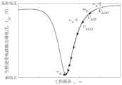
图5为发射端全桥逆变电路114经电压采集电路115检测到的


本实施例中,请参见图5和图6,基于梯度下降扫频寻优算法的频率自调谐实现包括以下步骤:In this embodiment, please refer to FIG. 5 and FIG. 6, the frequency self-tuning implementation based on the gradient descent sweep frequency optimization algorithm includes the following steps:
S1、结合图2,所述PWM脉冲发生器1123设定初始ω0的角频率,来驱动全桥逆变电路114工作,同时电压采集电路115检测当前全桥逆变电路114输出端电压作为ULC0;S1, in conjunction with Fig. 2, described
S2、首先计算ω0处的近似斜率,MCU控制器112根据设定的谐振频率角频率调节量Δω,检测ω0-Δω处全桥逆变电路114输出端电压作为ULC1;S2, first calculate the approximate slope at ω0 , the
S3、再检测ω0+Δω全桥逆变电路114输出端电压作为ULC2;此时ω0处的近似斜率设定为(ULC2-ULC1)/2Δω,梯度下降扫频寻优算法扫描步长设定为S=η(ULC2-ULC1)/2Δω,其中η表示学习率代表扫描迭代的快慢;S3. Then detect the voltage at the output terminal of ω0 +Δω full-
S4、基于以上扫描步长,可以分别得到一个较小的工作角频率ω1=ω0-S,和一个较大的工作角频率ω2=ω0+S,此时对应的全桥逆变电路114输出端电压分别为ULCS1和ULCS2,设定比较器1122的分辨率为ΔU,通过比较器1122比较ULCS1、ULC1、ULCS2的大小,MCU控制器112将其中最小值记为下一次ULC0暂存,S4. Based on the above scanning steps, a smaller operating angular frequency ω1 =ω0 -S and a larger operating angular frequency ω2 =ω0 +S can be obtained respectively. At this time, the corresponding full-bridge inverter The voltages at the output terminals of the
S5、经过多次调节,当ULCS1、ULC1、ULCS2之间的最大差距小于比较器1122分辨率ΔU时,此时停止扫频,最终使全桥逆变电路114输出电压最小,系统达到谐振状态,实现无线输电系统的谐振状态的闭环控制。S5. After multiple adjustments, when the maximum difference between ULCS1 , ULC1 , and ULCS2 is smaller than the resolution ΔU of the
梯度下降扫频优化算法模块1121根据比较器1122结果来控制频率输出,PWM脉冲发生器1123根据梯度下降扫频优化算法模块1121的输出频率产生PWM脉冲来控制全桥逆变电路114中的MOSFET管Q1-Q4的导通,如图3所示。The gradient descent frequency sweep
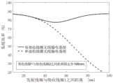
本实施例中,请参见图7,所述滑坡监测用频率自调谐的双接收端无线输电和通信装置中,双接收线圈组中稳定的接收线圈221和接收线圈222之间的距离固定在100mm,通过图7中双接收线圈无线输电系统与单接收线圈无线输电系统效率曲线可知,双接收线圈无线输电系统相较于单接收线圈无线输电系统具有更好的传输稳定性和效率。In this embodiment, please refer to Fig. 7, in the wireless power transmission and communication device with dual receiving terminals for frequency self-tuning of the landslide monitoring, the distance between the
需要说明的是,在本文中,术语“包括”、“包含”或者其任何其他变体意在涵盖非排他性的包含,从而使得包括一系列要素的过程、方法、物品或者系统不仅包括那些要素,而且还包括没有明确列出的其他要素,或者是还包括为这种过程、方法、物品或者系统所固有的要素。在没有更多限制的情况下,由语句“包括一个……”限定的要素,并不排除在包括该要素的过程、方法、物品或者系统中还存在另外的相同要素。It should be noted that, as used herein, the term "comprises", "comprises" or any other variation thereof is intended to cover a non-exclusive inclusion such that a process, method, article or system comprising a set of elements includes not only those elements, It also includes other elements not expressly listed, or elements inherent in the process, method, article, or system. Without further limitations, an element defined by the phrase "comprising a..." does not preclude the presence of additional identical elements in the process, method, article or system comprising that element.
上述本发明实施例序号仅仅为了描述,不代表实施例的优劣。在列举了若干装置的单元权利要求中,这些装置中的若干个可以是通过同一个硬件项来具体体现。词语第一、第二、以及第三等的使用不表示任何顺序,可将这些词语解释为标识。The serial numbers of the above embodiments of the present invention are for description only, and do not represent the advantages and disadvantages of the embodiments. In a unit claim enumerating several means, several of these means can be embodied by one and the same item of hardware. The use of the words first, second, and third etc. does not indicate any order and these words may be construed as designations.
以上仅为本发明的优选实施例,并非因此限制本发明的专利范围,凡是利用本发明说明书及附图内容所作的等效结构或等效流程变换,或直接或间接运用在其他相关的技术领域,均同理包括在本发明的专利保护范围内。The above are only preferred embodiments of the present invention, and are not intended to limit the patent scope of the present invention. Any equivalent structure or equivalent process conversion made by using the description of the present invention and the contents of the accompanying drawings, or directly or indirectly used in other related technical fields , are all included in the scope of patent protection of the present invention in the same way.
Claims (3)
Translated fromChinesePriority Applications (1)
| Application Number | Priority Date | Filing Date | Title |
|---|---|---|---|
| CN202110952029.XACN113809838B (en) | 2021-08-19 | 2021-08-19 | Frequency self-tuning dual-receiver wireless power transmission and communication device for landslide monitoring |
Applications Claiming Priority (1)
| Application Number | Priority Date | Filing Date | Title |
|---|---|---|---|
| CN202110952029.XACN113809838B (en) | 2021-08-19 | 2021-08-19 | Frequency self-tuning dual-receiver wireless power transmission and communication device for landslide monitoring |
Publications (2)
| Publication Number | Publication Date |
|---|---|
| CN113809838A CN113809838A (en) | 2021-12-17 |
| CN113809838Btrue CN113809838B (en) | 2023-06-02 |
Family
ID=78941546
Family Applications (1)
| Application Number | Title | Priority Date | Filing Date |
|---|---|---|---|
| CN202110952029.XAActiveCN113809838B (en) | 2021-08-19 | 2021-08-19 | Frequency self-tuning dual-receiver wireless power transmission and communication device for landslide monitoring |
Country Status (1)
| Country | Link |
|---|---|
| CN (1) | CN113809838B (en) |
Families Citing this family (1)
| Publication number | Priority date | Publication date | Assignee | Title |
|---|---|---|---|---|
| CN120511830A (en)* | 2025-07-22 | 2025-08-19 | 西安理工大学 | Underwater vehicle battery status monitoring system and power supply system based on wireless communication |
Citations (2)
| Publication number | Priority date | Publication date | Assignee | Title |
|---|---|---|---|---|
| CN107069990A (en)* | 2017-03-27 | 2017-08-18 | 华北电力大学(保定) | A kind of two-band magnet coupled resonant type wireless electric energy and signal synchronous transmission system |
| CN111610308A (en)* | 2020-04-27 | 2020-09-01 | 杭州电子科技大学 | A double-layer landslide monitoring system and method based on RTK technology |
Family Cites Families (12)
| Publication number | Priority date | Publication date | Assignee | Title |
|---|---|---|---|---|
| CN102163363B (en)* | 2011-04-07 | 2013-01-30 | 北京航空航天大学 | Landslide real-time monitoring and early warning system |
| US9683441B2 (en)* | 2011-11-03 | 2017-06-20 | Fastcap Systems Corporation | Power supply for wired pipe with rechargeable energy storage |
| EP3168995B1 (en)* | 2014-07-09 | 2020-09-09 | Hitachi, Ltd. | Large-scale sensor network system |
| US20180003851A1 (en)* | 2016-06-30 | 2018-01-04 | Trustees Of Boston University | Wireless fluidic readout platform for sensors |
| CN111486827A (en)* | 2019-01-29 | 2020-08-04 | 瑞典爱立信有限公司 | Wireless sensor for detecting geological changes and system comprising same |
| CN109862533A (en)* | 2019-03-29 | 2019-06-07 | 蓝蛛科技(杭州)有限公司 | A landslide monitoring and early warning system based on wireless sensor network |
| CN111262349B (en)* | 2019-09-04 | 2021-12-07 | 西南交通大学 | Design method of magnetic coupling mechanism of double-pickup-coil wireless energy transfer device |
| CN110608691B (en)* | 2019-09-05 | 2021-03-09 | 三峡大学 | Real-time monitoring system and method of landslide deep displacement based on sound source localization |
| CN110736498B (en)* | 2019-09-12 | 2020-09-29 | 中国地质大学(武汉) | System and method for monitoring multiple parameters outside deep hole of sliding body |
| US11681063B2 (en)* | 2019-09-13 | 2023-06-20 | Sercel | Multi-function acquisition device and operating method |
| CN113175912B (en)* | 2021-03-30 | 2022-05-24 | 中国地质大学(武汉) | Unmanned Landslide Lateral Deformation Monitoring System and Method Based on Inertial Measurement Technology |
| CN113137985B (en)* | 2021-05-14 | 2022-02-18 | 中国地质大学(武汉) | Equipment and method for laying multi-integrated sensors in deep part of landslide |
- 2021
- 2021-08-19CNCN202110952029.XApatent/CN113809838B/enactiveActive
Patent Citations (2)
| Publication number | Priority date | Publication date | Assignee | Title |
|---|---|---|---|---|
| CN107069990A (en)* | 2017-03-27 | 2017-08-18 | 华北电力大学(保定) | A kind of two-band magnet coupled resonant type wireless electric energy and signal synchronous transmission system |
| CN111610308A (en)* | 2020-04-27 | 2020-09-01 | 杭州电子科技大学 | A double-layer landslide monitoring system and method based on RTK technology |
Non-Patent Citations (1)
| Title |
|---|
| 梯度下降算法在时间同步中的优化;刘云;肖雪;;西北大学学报(自然科学版)(第05期);659-664* |
Also Published As
| Publication number | Publication date |
|---|---|
| CN113809838A (en) | 2021-12-17 |
Similar Documents
| Publication | Publication Date | Title |
|---|---|---|
| US9091144B2 (en) | Environmentally powered transmitter for location identification of wellbores | |
| US10163564B2 (en) | Wireless power transmitter and method of controlling power thereof | |
| KR101262615B1 (en) | Apparatus for transmitting wireless power, apparatus for receiving wireless power, system for transmitting wireless power and method for transmitting wireless power | |
| CN107124046B (en) | Wireless charging system with living body detection function and wireless charging method | |
| KR101543059B1 (en) | Wireless power receiving device and power control method thereof | |
| US20130051083A1 (en) | Magnetic coupling and contactless power transmission apparatus | |
| US20130154373A1 (en) | Primary unit control of resonant inductive power transfer system for optimum efficiency | |
| GB2599283A (en) | Systems and methods for wireless power transmission in a well | |
| CN108879869B (en) | Primary-side control method and implementation system of wireless charging system based on load characteristics | |
| CN110554236B (en) | Frequency online detection method for constant voltage or constant current output of wireless power transmission | |
| CN113809838B (en) | Frequency self-tuning dual-receiver wireless power transmission and communication device for landslide monitoring | |
| CN104216021B (en) | Underground nuclear magnetic resonance exploration method based on step-by-step transmission | |
| CN111740508A (en) | Control method and system of wireless charging system | |
| Yao et al. | Design of intelligent vehicle based on dynamic wireless charging | |
| CN112510851B (en) | High-voltage power taking circuit, device, control method and high-voltage power taking device | |
| Hata et al. | Dynamic wireless power transfer system for electric vehicle to simplify ground facilities-power control based on vehicle-side information | |
| CN103944280A (en) | Device and method for dynamic tuning of sending end of wireless power transmission device | |
| KR101822213B1 (en) | Apparatus for transmitting wireless power, apparatus for receiving wireless power, system for transmitting wireless power and method for transmitting wireless power | |
| CN106886052B (en) | A high-power nuclear magnetic resonance water detection device and its field use method | |
| WO2012073472A1 (en) | Electrical power transmission system | |
| KR101428162B1 (en) | Apparatus for supplying power and apparatus for transmitting wireless power and method for detecting resonance frequency | |
| KR101360744B1 (en) | Apparatus for transmitting wireless power, apparatus for receiving wireless power, system for transmitting wireless power and method for transmitting wireless power | |
| CN206671580U (en) | Nuclear magnetic resonance based on array inversion charging visits water emitter | |
| KR101905882B1 (en) | Apparatus for transmitting wireless power, apparatus for receiving wireless power, system for transmitting wireless power and method for transmitting wireless power | |
| CN102291012A (en) | Energy storage and power conversion device for underground directional probe |
Legal Events
| Date | Code | Title | Description |
|---|---|---|---|
| PB01 | Publication | ||
| PB01 | Publication | ||
| SE01 | Entry into force of request for substantive examination | ||
| SE01 | Entry into force of request for substantive examination | ||
| GR01 | Patent grant | ||
| GR01 | Patent grant |