CN113805268B - Dot structure, striker structure and striker process of a light guide plate - Google Patents
Dot structure, striker structure and striker process of a light guide plateDownload PDFInfo
- Publication number
- CN113805268B CN113805268BCN202111164079.8ACN202111164079ACN113805268BCN 113805268 BCN113805268 BCN 113805268BCN 202111164079 ACN202111164079 ACN 202111164079ACN 113805268 BCN113805268 BCN 113805268B
- Authority
- CN
- China
- Prior art keywords
- light
- receiving surface
- guide plate
- light receiving
- light guide
- Prior art date
- Legal status (The legal status is an assumption and is not a legal conclusion. Google has not performed a legal analysis and makes no representation as to the accuracy of the status listed.)
- Active
Links
- 238000000034methodMethods0.000titleclaimsabstractdescription18
- 230000001154acute effectEffects0.000claimsabstractdescription10
- 239000002184metalSubstances0.000claimsdescription20
- 238000001746injection mouldingMethods0.000claimsdescription3
- 238000010304firingMethods0.000claims3
- 238000000465mouldingMethods0.000claims1
- 230000009286beneficial effectEffects0.000description28
- 238000010586diagramMethods0.000description17
- 239000000243solutionSubstances0.000description14
- 230000003287optical effectEffects0.000description5
- 230000000694effectsEffects0.000description4
- 238000009792diffusion processMethods0.000description3
- 238000007731hot pressingMethods0.000description3
- 239000000463materialSubstances0.000description3
- 230000005540biological transmissionEffects0.000description1
- 238000005516engineering processMethods0.000description1
- 230000002708enhancing effectEffects0.000description1
- 230000002349favourable effectEffects0.000description1
- 238000002347injectionMethods0.000description1
- 239000007924injectionSubstances0.000description1
- 239000004973liquid crystal related substanceSubstances0.000description1
- 108091008695photoreceptorsProteins0.000description1
- 238000005498polishingMethods0.000description1
- 229920003229poly(methyl methacrylate)Polymers0.000description1
- 239000004926polymethyl methacrylateSubstances0.000description1
Images


Classifications
- G—PHYSICS
- G02—OPTICS
- G02B—OPTICAL ELEMENTS, SYSTEMS OR APPARATUS
- G02B6/00—Light guides; Structural details of arrangements comprising light guides and other optical elements, e.g. couplings
- G02B6/0001—Light guides; Structural details of arrangements comprising light guides and other optical elements, e.g. couplings specially adapted for lighting devices or systems
- G02B6/0011—Light guides; Structural details of arrangements comprising light guides and other optical elements, e.g. couplings specially adapted for lighting devices or systems the light guides being planar or of plate-like form
- G02B6/0033—Means for improving the coupling-out of light from the light guide
- G02B6/0035—Means for improving the coupling-out of light from the light guide provided on the surface of the light guide or in the bulk of it
- G02B6/004—Scattering dots or dot-like elements, e.g. microbeads, scattering particles, nanoparticles
- G02B6/0043—Scattering dots or dot-like elements, e.g. microbeads, scattering particles, nanoparticles provided on the surface of the light guide
- G—PHYSICS
- G02—OPTICS
- G02B—OPTICAL ELEMENTS, SYSTEMS OR APPARATUS
- G02B6/00—Light guides; Structural details of arrangements comprising light guides and other optical elements, e.g. couplings
- G02B6/0001—Light guides; Structural details of arrangements comprising light guides and other optical elements, e.g. couplings specially adapted for lighting devices or systems
- G02B6/0011—Light guides; Structural details of arrangements comprising light guides and other optical elements, e.g. couplings specially adapted for lighting devices or systems the light guides being planar or of plate-like form
- G02B6/0065—Manufacturing aspects; Material aspects
Landscapes
- Physics & Mathematics (AREA)
- General Physics & Mathematics (AREA)
- Optics & Photonics (AREA)
- Engineering & Computer Science (AREA)
- Manufacturing & Machinery (AREA)
- Planar Illumination Modules (AREA)
Abstract
Translated fromChinese
Description
Translated fromChinese技术领域technical field
本申请涉及导光结构技术领域,尤其是涉及一种导光板的网点结构、撞针结构以及撞点工艺。The present application relates to the technical field of light guide structures, and in particular, to a dot structure, a striker structure and a strike point process of a light guide plate.
背景技术Background technique
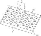
导光板一般应用于液晶显示器中,参见图1,导光板包括导光板本体1。导光板本体1设置有入光侧、出光侧、网点面102和出光面101,导光板本体1靠近光源11的一侧为入光侧,导光板本体1靠近光源11的一侧为出光侧,导光板本体1的出光面101位于入光侧和出光侧之间,且网点面102位于出光面101的相对面。光源11发出的光线从导光板本体1的入光侧进入导光板本体1,经反射和扩散后从导光板本体1的出光面101出射,以形成面光源11提供给显示面板。A light guide plate is generally used in a liquid crystal display. Referring to FIG. 1 , the light guide plate includes a light
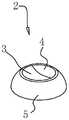
目前,一般在导光板本体1的网点面102上设置呈凸起设置的网点结构2,这些网点结构2的作用就是改变光线的传播方向。导光板的网点结构2的正投影通常呈圆形,网点结构2主要是由热压、激光或射出工艺制备成型。At present, the
针对上述技术,发明人认为,利用该网点结构2对光线进行漫反射时,由于受光面的面积较小,漫反射散射光线漏失严重,会导致导光板的出光亮度较低。In view of the above technology, the inventor believes that when the
发明内容SUMMARY OF THE INVENTION
第一方面,为了有利于提高导光板的出光亮度,本申请提供一种导光板的网点结构。In the first aspect, in order to help improve the light-emitting brightness of the light guide plate, the present application provides a dot structure of the light guide plate.
本申请提供的一种导光板的网点结构,采用如下的技术方案:The dot structure of a light guide plate provided by the application adopts the following technical solutions:
一种导光板的网点结构,用于安装于导光板本体的网点面上,所述网点结构包括第一受光面、第二受光面以及若干第一连接面,所述第一受光面与所述第二受光面相互连接,所述第一受光面背离所述第二受光面的一侧与所述导光板本体的网点面连接,所述第二受光面远离所述第一受光面的一侧与所述导光板本体的网点面连接;所述第一受光面与所述第二受光面的另外两侧边分别通过所述第一连接面与所述网点面连接,所述第一受光面与所述网点面的夹角为锐角,且所述第一受光面与所述第二受光面之间的夹角的角度范围为60°-170°。A dot structure of a light guide plate is used to be installed on a dot surface of a light guide plate body, the dot structure includes a first light receiving surface, a second light receiving surface and a plurality of first connecting surfaces, the first light receiving surface and the The second light-receiving surfaces are connected to each other, the side of the first light-receiving surface facing away from the second light-receiving surface is connected to the dot surface of the light guide plate body, and the second light-receiving surface is far from the first light-receiving surface. connected with the dot surface of the light guide plate body; the other two sides of the first light-receiving surface and the second light-receiving surface are respectively connected to the dot surface through the first connection surface, and the first light-receiving surface The included angle with the dot surface is an acute angle, and the included angle between the first light-receiving surface and the second light-receiving surface ranges from 60° to 170°.
通过采用上述技术方案,网点结构设置在导光板的网点面上,以用于将入射光线反射至出光面,网点结构中的第一受光面和第二受光面相互连接,第一受光面与网点面的夹角为锐角,使得更多的光线能射至第一受光面上,有利于增大光线的扩散范围;基于第一受光面与网点面的夹角为锐角的情况下,将第一受光面与第二受光面的夹角的角度范围为60°-170°,一方面使得第二受光面能够对直接射向出光侧处的光线起到指向性引导的作用,有利于使得更多的光线能反射至出光面,因此有利于提高导光板的出光亮度,另一方面,第二受光面使得光线能够反射至出光面靠近出光侧的位置,有利于将反射的光线能均匀分布在出光面上;第一受光面与第二受光面的另外两侧边分别通过第一连接面与网点面连接,第一连接面的设置有利于将入射的光线进行收拢,使得更多的光线能够射至第一受光面以及第二受光面处,第一受光面以及第二受光面配合增大了网点结构的受光面积,有利于进一步提高导光板的出光亮度。By adopting the above technical solution, the dot structure is arranged on the dot surface of the light guide plate to reflect the incident light to the light emitting surface, the first light receiving surface and the second light receiving surface in the dot structure are connected to each other, and the first light receiving surface and the dots The angle between the surfaces is an acute angle, so that more light can reach the first light-receiving surface, which is beneficial to increase the diffusion range of light; based on the case where the angle between the first light-receiving surface and the dot surface is an acute angle, The angle between the light-receiving surface and the second light-receiving surface ranges from 60° to 170°. On the one hand, the second light-receiving surface can play a directional guiding role for the light directly emitted to the light-emitting side, which is conducive to making more The light can be reflected to the light-emitting surface, so it is beneficial to improve the light-emitting brightness of the light guide plate. On the other hand, the second light-receiving surface enables the light to be reflected to the position of the light-emitting surface close to the light-emitting side, which is beneficial to distribute the reflected light evenly on the light-emitting surface. The other two sides of the first light-receiving surface and the second light-receiving surface are respectively connected with the dot surface through the first connecting surface, and the setting of the first connecting surface is conducive to collecting the incident light, so that more light can be emitted To the first light-receiving surface and the second light-receiving surface, the cooperation of the first light-receiving surface and the second light-receiving surface increases the light-receiving area of the dot structure, which is beneficial to further improve the light-emitting brightness of the light guide plate.
优选的,所述第一受光面包括相互连接的第一受光子面以及第二受光子面,所述第二受光面包括相互连接的第三受光子面以及第四受光子面,所述第一受光子面的侧边与所述第三受光子面的侧边相连接并形成夹角,所述第二受光子面的侧边与所述第四受光子面的侧边相连接并形成夹角;所述第一受光子面、所述第二受光子面、所述第三受光子面以及所述第四受光子面分别通过第一连接面与所述网点面连接并形成夹角。Preferably, the first light-receiving surface includes a first light-receiving surface and a second light-receiving surface that are connected to each other, the second light-receiving surface includes a third light-receiving surface and a fourth light-receiving surface that are connected to each other, and the first light-receiving surface The side of a photo-receiving surface is connected with the side of the third photo-receiving surface and forms an included angle, and the side of the second photo-receiving surface is connected with the side of the fourth photo-receiving surface and forms an included angle. Included angle; the first photoreceiving surface, the second photoreceiving surface, the third photoreceiving surface and the fourth photoreceiving surface are respectively connected with the dot surface through the first connection surface to form an included angle .
通过采用上述方案,第一受光子面与第二受光子面连接并形成夹角,第三受光子面与第四受光子面连接并形成夹角,使得第一受光子面、第二受光子面、第三受光子面以及第四受光子面组合形成具有收拢光线的结构,以降低入射的光线直接从导光板的出光侧穿出的可能性,使得更多的光线能够反射至导光板的出光面上。By adopting the above scheme, the first photon-receiving surface is connected to the second photon-receiving surface and forms an included angle, and the third photon-receiving surface is connected to the fourth photon-receiving surface and forms an included angle, so that the first photon-receiving surface and the second photon-receiving surface are connected to form an included angle. The light-receiving surface, the third photon-receiving surface and the fourth photon-receiving surface are combined to form a structure that condenses light to reduce the possibility of incident light passing directly from the light-emitting side of the light guide plate, so that more light can be reflected to the light guide plate. on the surface of the light.
优选的,所述第一受光子面设有第一侧边,所述第二受光子面设有第二侧边,所述第三受光子面设置有第三侧边,所述第四受光子面设置有第四侧边,所述第一侧边、所述第二侧边、所述第三侧边以及所述第四侧边组合形成第三受光面,所述第三受光面正投影于所述网点面的形状为正方形。Preferably, the first light-receiving surface is provided with a first side, the second light-receiving surface is provided with a second side, the third light-receiving surface is provided with a third side, and the fourth light-receiving surface is provided with a third side. The photon surface is provided with a fourth side, the first side, the second side, the third side and the fourth side are combined to form a third light-receiving surface, and the third light-receiving surface is positive The shape projected on the dot plane is a square.
通过采用上述方案,第三受光面的设置有利于增大网点结构的受光面积,使得更多的入射光线射至第三受光面后也能够反射至导光板的出光面,由此有利于提高导光板的出光面的亮度。By adopting the above solution, the arrangement of the third light-receiving surface is beneficial to increase the light-receiving area of the dot structure, so that more incident light can be reflected to the light-exiting surface of the light guide plate after hitting the third light-receiving surface, which is beneficial to improve the light-guiding surface. The brightness of the light-emitting surface of the light plate.
优选的,所述第一连接面、所述第一受光面、所述第二受光面以及所述第三受光面均为平面。Preferably, the first connection surface, the first light-receiving surface, the second light-receiving surface and the third light-receiving surface are all flat surfaces.
通过采用上述方案,第一连接面、第一受光面、第二受光面以及第三受光面均呈平面设置,一方面有利于有效对朝向出光侧的方向射出的入射光线起到指向性引导的作用,另一方面有利于扩大光线反射后落在导光板的出光面的范围,因此有利于实现入射光能够更加均匀地分布于导光板的出光面上。By adopting the above solution, the first connection surface, the first light-receiving surface, the second light-receiving surface and the third light-receiving surface are all arranged in a plane, which is beneficial to effectively guide the incident light in the direction of the light-emitting side. On the other hand, it is beneficial to expand the range of the light emitting surface of the light guide plate after reflection, so it is beneficial to realize that the incident light can be more uniformly distributed on the light emitting surface of the light guide plate.
优选的,所述第一连接面、所述第一受光面以及所述第二受光面均为曲面,且所述第一受光面与所述第二受光面连接形成朝向所述出光面的方向凸出的曲面。Preferably, the first connection surface, the first light-receiving surface and the second light-receiving surface are all curved surfaces, and the first light-receiving surface and the second light-receiving surface are connected to form a direction toward the light-emitting surface convex surface.
通过采用上述方案,第一连接面、第一受光面以及第二受光面均为曲面,在保证对朝向出光侧射出的入射光起到指向性引导作用的条件下,一方面有利于使得第一受光面以及第二受光面接受到的入射光能更多地反射至导光板的出光面,另一方面,第一受光面与所述第二受光面连接形成朝向所述出光面的方向凸出的曲面,使得入射光经过该曲面的反射后能够从不同的方向射至导光板的出光面上,由此能够使得导光板的出光面上的光线更柔和。By adopting the above solution, the first connecting surface, the first light-receiving surface and the second light-receiving surface are all curved surfaces. On the condition that the incident light emitted toward the light-emitting side can be directionally guided, on the one hand, it is beneficial to make the first connection surface, the first light-receiving surface and the second light-receiving surface all curved The incident light received by the light-receiving surface and the second light-receiving surface can be more reflected to the light-emitting surface of the light guide plate. The curved surface enables incident light to strike the light emitting surface of the light guide plate from different directions after being reflected by the curved surface, thereby making the light on the light emitting surface of the light guide plate softer.
优选的,所述第一连接面为曲面,所述第一受光面以及所述第二受光面均为平面,且所述第一受光面与所述第二受光面连接处朝向所述出光面的方向突出并形成夹角,且所述夹角的角度范围为60°-170°。Preferably, the first connection surface is a curved surface, the first light-receiving surface and the second light-receiving surface are both flat surfaces, and the connection between the first light-receiving surface and the second light-receiving surface faces the light-emitting surface The direction protrudes and forms an included angle, and the angle range of the included angle is 60°-170°.
通过采用上述方案,第一连接面为曲面,实现对朝向出光侧射出的入射光起到指向性引导作用,有利于提高入射光的利用率;基于第一连接面为曲面的条件下,第一受光面以及所述第二受光面均为平面,且第一受光面与第二受光面连接处朝向所述出光面的方向突出并形成角度范围为60°-170°的夹角,能够实现接收更多的入射光,同时能够使得第二受光面将更多的光线扩散至导光板的出光面上,从而使得入射光能更均匀地分布在导光板的出光面。By adopting the above solution, the first connecting surface is a curved surface, so as to play a directional guiding role for the incident light emitted toward the light-emitting side, which is beneficial to improve the utilization rate of the incident light; based on the condition that the first connecting surface is a curved surface, the first connecting surface is a curved surface. The light-receiving surface and the second light-receiving surface are both flat surfaces, and the connection between the first light-receiving surface and the second light-receiving surface protrudes toward the light-emitting surface and forms an included angle with an angle range of 60°-170°, which can realize receiving With more incident light, the second light receiving surface can diffuse more light to the light emitting surface of the light guide plate, so that the incident light can be more evenly distributed on the light emitting surface of the light guide plate.
优选的,所述导光板本体的出光面上开设有多个切槽。Preferably, a plurality of cut grooves are formed on the light emitting surface of the light guide plate body.
通过采用上述方案,导光板本体的出光面上设有多个切槽,有利于增大导光板的出光面的面积,从而有利于使得导光板出光面的出光更均匀。By adopting the above solution, the light emitting surface of the light guide plate body is provided with a plurality of notches, which is beneficial to increase the area of the light emitting surface of the light guide plate, thereby making the light emitting surface of the light guide plate more uniform.
第二方面,为了加工得到上述方案中的导光板,本申请提供一种用于加工导光板的撞针结构。In the second aspect, in order to process the light guide plate in the above solution, the present application provides a striker structure for processing the light guide plate.
本申请提供的一种用于加工导光板的网点结构的撞针结构,采用如下的技术方案:A striker structure for processing the dot structure of the light guide plate provided by the application adopts the following technical solutions:
一种用于加工导光板的网点结构的撞针结构,包括针杆和撞点头,所述针杆用于可拆卸安装于撞点机,所述撞点头包括连接部以及凸起部,所述连接部的一端与所述针杆的一端固定连接,所述凸起部包括第一面、第二面以及若干第二连接面,所述第一面与所述第二面相互连接,所述第一面背离所述第二面的侧边与所述连接部侧面的侧边相连接,所述第二面远离所述第一面的侧边与所述连接部另一侧面的侧边相连接;所述第一面与所述第二面的另外两侧边分别通过所述第二连接面与所述连接部连接,所述第一面与所述连接部的侧面夹角为锐角,且所述第一面与所述第二面之间的夹角的角度范围为60°-170°。A striker structure for processing a dot structure of a light guide plate, comprising a needle bar and a striker head, wherein the needle bar is used to be detachably installed on a striker, the striker head comprises a connection part and a raised part, the connection part One end of the needle bar is fixedly connected to one end of the needle bar, the raised portion includes a first surface, a second surface and a plurality of second connecting surfaces, the first surface and the second surface are connected to each other, and the first surface and the second surface are connected to each other. The side of the face away from the second face is connected with the side of the side of the connecting portion, and the side of the second face away from the first face is connected with the side of the other side of the connecting portion; The other two sides of the first surface and the second surface are respectively connected to the connecting portion through the second connecting surface, and the included angle between the side surfaces of the first surface and the connecting portion is an acute angle, and the The angle range of the included angle between the first surface and the second surface is 60°-170°.
通过采用上述方案,针杆可拆卸安装于撞点机,以便于工作人员更换撞针;连接部与针杆固定连接,凸起部通过连接部与针杆固定连接,使得撞针的撞点头能更有效地用于加工导光板;而且,凸起部由第一面、第二面以及若干第二连接面连接而成,使得凸起部的形状与需要在导光板加工形成的网点结构的形状相适配,有利于导光板上的网点结构一次成型。By adopting the above solution, the needle bar can be detachably installed on the striker, so that the staff can replace the striker; the connecting part is fixedly connected with the needle bar, and the raised part is fixedly connected with the needle bar through the connecting part, so that the striker of the striker can be more effectively It is used to process the light guide plate; moreover, the raised part is formed by connecting the first surface, the second surface and several second connecting surfaces, so that the shape of the raised part matches the shape of the dot structure that needs to be processed on the light guide plate , which is conducive to the one-time forming of the dot structure on the light guide plate.
优选的,所述第一面包括相互连接的第一子面以及第二子面,所述第二面包括相互连接的第三子面以及第四子面,所述第一子面的侧边与所述第三子面的侧边相连接并形成夹角,所述第二子面的侧边与所述第四子面的侧边相连接并形成夹角;所述第一子面、所述第二子面、所述第三子面以及所述第四子面分别通过第二连接面与所述网点面连接。Preferably, the first surface includes a first subsurface and a second subsurface that are connected to each other, the second surface includes a third subsurface and a fourth subsurface that are connected to each other, and the side edges of the first subsurface is connected with the side of the third sub-surface and forms an included angle, the side of the second sub-surface is connected with the side of the fourth sub-surface and forms an included angle; the first sub-surface, The second sub-surface, the third sub-surface and the fourth sub-surface are respectively connected to the dot surface through a second connection surface.
通过采用上述方案,第一子面与第二子面连接并形成夹角,第三子面与第四子面连接并形成,使得第一子面、第二子面、第三子面以及第四子面组合形成网点结构,有利于提高撞针结构能更加准确地加工得到导光板处的网点结构。By adopting the above solution, the first sub-surface is connected with the second sub-surface and forms an included angle, and the third sub-surface is connected and formed with the fourth sub-surface, so that the first sub-surface, the second sub-surface, the third sub-surface and the The combination of the four sub-surfaces forms a dot structure, which is beneficial to improve the striker structure and can more accurately process the dot structure at the light guide plate.
优选的,所述第二连接面、所述第一面以及所述第二面均为曲面,且所述第一面与所述第二面连接形成朝向所述连接部的方向凸出的曲面。Preferably, the second connecting surface, the first surface and the second surface are all curved surfaces, and the first surface and the second surface are connected to form a curved surface that protrudes toward the connecting portion .
通过采用上述方案,第二连接面为曲面,一方面能够实现配合加工对应的网点结构,另一方面有利于节省对网点结构进行二次抛光打磨的工序,有利于提高导光板网点结构的加工效率。By adopting the above scheme, the second connecting surface is a curved surface, on the one hand, the corresponding mesh structure can be realized, and on the other hand, it is beneficial to save the process of secondary polishing and grinding of the mesh structure, which is beneficial to improve the processing efficiency of the mesh structure of the light guide plate. .
第三方面,为了加工得到上述方案中的导光板,本申请提供一种用于加工导光板的网点结构的撞点工艺。In the third aspect, in order to process the light guide plate in the above solution, the present application provides a collision point process for processing the dot structure of the light guide plate.
本申请提供的一种用于加工导光板的网点结构的撞点工艺,采用如下的技术方案:A kind of collision point process for processing the dot structure of the light guide plate provided by the application adopts the following technical scheme:
一种用于加工上述方案中任一项所述的导光板的网点结构的撞点工艺,包括:A hit point process for processing the dot structure of the light guide plate according to any one of the above solutions, comprising:
采用上述方案中任一项的撞针结构通过机械撞击在金属模芯上形成多个凸状网点,以得到带有凸状网点的金属模芯;Adopt the striker structure of any one of the above solutions to form a plurality of convex mesh points on the metal mold core by mechanical impact, so as to obtain a metal mold core with convex mesh points;
采用所述金属模芯通过注塑成型或热压成型以将金属模芯上的凸状网点转写至导光板的网点面,制得具有网点结构的导光板。The metal mold core is used to transfer the convex mesh points on the metal mold core to the mesh point surface of the light guide plate by injection molding or hot pressing, so as to prepare a light guide plate with a mesh point structure.
通过采用上述方案,先采用上述方案中的撞针结构来制得金属模芯,使得金属模芯具有凸状网点,再采用金属模芯将凸状网点转写至导光板上,使得导光板的网点面上形成多个网点结构,实现加工形成带有网点结构的导光板。By adopting the above scheme, the striker structure in the above scheme is used to prepare the metal mold core, so that the metal mold core has convex mesh points, and then the metal mold core is used to transfer the convex mesh points to the light guide plate, so that the mesh points of the light guide plate are A plurality of dot structures are formed on the surface to realize processing to form a light guide plate with dot structures.
综上所述,本申请包括以下至少一种有益技术效果:To sum up, the present application includes at least one of the following beneficial technical effects:
1. 网点结构中的第一受光面和第二受光面相互连接,第一受光面与所述网点面的夹角为锐角,使得更多的光线能射至第一受光面上,有利于增大光线的扩散范围;基于第一受光面与网点面的夹角为锐角的情况下,将第一受光面与第二受光面的夹角的角度范围设为60°-170°,一方面使得第二受光面能够对直接射向出光侧处的光线起到指向性引导的作用,有利于使得更多的光线能反射至出光面,因此有利于提高亮度,另一方面,第二受光面使得光线能够反射至出光面靠近出光侧的位置,有利于将反射的光线能均匀分布在出光面上;第一受光面与第二受光面的另外两侧边分别通过第一连接面与网点面连接,第一连接面的设置有利于将入射的光线进行收拢,使得更多的光线能够射至第一受光面以及第二受光面处,第一受光面以及第二受光面配合增大了网点结构的受光面积,有利于进一步提高导光板的出光亮度。1. The first light-receiving surface and the second light-receiving surface in the dot structure are connected to each other, and the angle between the first light-receiving surface and the dot surface is an acute angle, so that more light can be emitted to the first light-receiving surface, which is conducive to increasing the Large light diffusion range; based on the fact that the angle between the first light-receiving surface and the dot surface is an acute angle, the angle range of the angle between the first light-receiving surface and the second light-receiving surface is set to 60°-170°. The second light-receiving surface can play a directional guiding role for the light directly emitted to the light-emitting side, which is beneficial to make more light reflect to the light-emitting surface, so it is beneficial to improve the brightness. On the other hand, the second light-receiving surface makes The light can be reflected to the position of the light-emitting surface close to the light-emitting side, which is conducive to evenly distributing the reflected light on the light-emitting surface; the other two sides of the first light-receiving surface and the second light-receiving surface are respectively connected with the dot surface through the first connecting surface The arrangement of the first connecting surface is conducive to collecting the incident light, so that more light can be emitted to the first light-receiving surface and the second light-receiving surface. The cooperation of the first light-receiving surface and the second light-receiving surface increases the dot structure. It is beneficial to further improve the light-emitting brightness of the light guide plate.
2. 第一连接面、第一受光面、第二受光面以及第三受光面均呈平面设置,一方面有利于有效对朝向出光侧的方向射出的入射光线起到指向性引导的作用,另一方面有利于扩大光线反射后落在导光板的出光面的范围,因此有利于实现入射光能够更加均匀地分布于导光板的出光面上。2. The first connecting surface, the first light-receiving surface, the second light-receiving surface and the third light-receiving surface are all arranged in a plane. On the one hand, it is beneficial to expand the range of the reflected light falling on the light exit surface of the light guide plate, so it is beneficial to realize that the incident light can be more uniformly distributed on the light exit surface of the light guide plate.
3. 第一受光子面与第二受光子面连接并形成夹角的角度范围为60°-170°,第三受光子面与第四受光子面连接并形成夹角的角度范围为60°-170°,使得第一受光子面、第二受光子面、第三受光子面以及第四受光子面组合形成具有收拢光线的结构,有利于进一步将入射的光线收拢,以降低入射的光线直接从导光板的出光侧穿出的可能性,使得更多的光线能够反射至导光板的出光面上,有利于降低光损、提高光能利用率,同时有利于提高导光板的出光亮度。3. The angle range between the first photoreceiving surface and the second photoreceiving surface is 60°-170°, and the angle where the third photoreceiving surface is connected to the fourth photoreceptor surface is 60° -170°, so that the first photon-receiving surface, the second photon-receiving surface, the third photon-receiving surface and the fourth photon-receiving surface are combined to form a structure with a light-receiving structure, which is conducive to further condensing the incident light and reducing the incident light. The possibility of directly exiting from the light-emitting side of the light guide plate allows more light to be reflected on the light-emitting surface of the light guide plate, which is conducive to reducing light loss, improving the utilization rate of light energy, and improving the light output brightness of the light guide plate.
附图说明Description of drawings
图1是相关技术中具有网点结构的导光板的结构示意图。FIG. 1 is a schematic structural diagram of a light guide plate with a dot structure in the related art.
图2是本申请实施例1中导光板的结构示意图。FIG. 2 is a schematic structural diagram of a light guide plate in
图3是本申请实施例1中导光板的正投影图。FIG. 3 is an orthographic view of the light guide plate in
图4是本申请实施例1中导光板的光路原理图。FIG. 4 is a schematic diagram of the light path of the light guide plate in
图5是本申请实施例2一种实施方式中导光板的结构示意图。FIG. 5 is a schematic structural diagram of a light guide plate in an implementation manner of Example 2 of the present application.
图6是本申请实施例2一种实施方式中导光板的正投影图。FIG. 6 is an orthographic view of a light guide plate in an implementation manner of Example 2 of the present application.
图7是本申请实施例2中网点结构呈简略显示时,导光板的光路原理图。FIG. 7 is a schematic diagram of the light path of the light guide plate when the dot structure in
图8是本申请实施例2中另一种实施方式中导光板的结构示意图。FIG. 8 is a schematic structural diagram of a light guide plate in another implementation manner in Example 2 of the present application.
图9是本申请实施例2中另一种实施方式中导光板的正投影图。FIG. 9 is an orthographic view of a light guide plate in another implementation manner in Example 2 of the present application.
图10是本申请实施例2另一种实施方式中网点结构呈简略显示时,导光板的光路原理图。FIG. 10 is a schematic diagram of the light path of the light guide plate in another implementation manner of the second embodiment of the present application when the dot structure is shown briefly.
图11是本申请实施例2其他实施方式中导光板的正投影图。FIG. 11 is an orthographic view of a light guide plate in another implementation manner of Example 2 of the present application.
图12是本申请实施例2其他实施方式中导光板的光路原理图。FIG. 12 is a schematic diagram of an optical path of a light guide plate in another implementation manner of Example 2 of the present application.
图13是本申请实施例3一种实施方式中导光板的结构图。FIG. 13 is a structural diagram of a light guide plate in an implementation manner of Example 3 of the present application.
图14是本申请实施例3一种实施方式中导光板的正投影图。FIG. 14 is an orthographic view of a light guide plate in an embodiment of Example 3 of the present application.
图15是本申请实施例3一种实施方式中导光板的光路原理图。FIG. 15 is a schematic diagram of an optical path of a light guide plate in an implementation manner of Example 3 of the present application.
图16是本申请实施例3另一种实施方式中网点结构的结构示意图。FIG. 16 is a schematic structural diagram of a dot structure in another implementation manner of
图17是本申请实施例3另一种实施方式中导光板的正投影图。FIG. 17 is an orthographic view of a light guide plate in another implementation manner of Example 3 of the present application.
图18是本申请实施例3另一种实施方式中导光板的光路原理图。FIG. 18 is a schematic diagram of an optical path of a light guide plate in another implementation manner of Example 3 of the present application.
图19是本申请实施例中撞针的结构示意图。FIG. 19 is a schematic structural diagram of a striker in an embodiment of the present application.
图20是本申请实施例中撞针的仰视图。FIG. 20 is a bottom view of the striker in the embodiment of the present application.
图21是本申请一实施方式中撞针的结构示意图。FIG. 21 is a schematic structural diagram of a striker in an embodiment of the present application.
图22是本申请一实施方式中撞点头的结构示意图。FIG. 22 is a schematic structural diagram of a bump head in an embodiment of the present application.
图23是本申请一实施方式中撞点头的仰视图。FIG. 23 is a bottom view of the bump head in an embodiment of the present application.
图24是本申请另一实施方式中撞点头的仰视图。FIG. 24 is a bottom view of the bump head in another embodiment of the present application.
图25是本申请一实施方式中撞点头的结构剖视图。FIG. 25 is a cross-sectional view of the structure of an impact head according to an embodiment of the present application.
图26是本申请另一实施方式中撞点头的结构剖视图。FIG. 26 is a cross-sectional view of the structure of an impact head in another embodiment of the present application.
附图标记说明:Description of reference numbers:
1、导光板本体;101、出光面;1011、切槽;102、网点面;2、网点结构;3、第一受光面;31、第一受光子面;311、第一侧边;32、第二受光子面;321、第二侧边;4、第二受光面;41、第三受光子面;411、第三侧边;42、第四受光子面;421、第四侧边;5、第一连接面;6、第三受光面;7、针杆;8、撞点头;9、凸起部;91、第一面;911、第一子面;9111、第一边;912、第二子面;9121、第二边;92、第二面;921、第三子面;9211、第三边;922、第四子面;9221、第四边;93、第二连接面;94、第三面;10、连接部;11、光源。1. Light guide plate body; 101. Light-emitting surface; 1011. Grooving; 102. Dot surface; 2. Dot structure; 3. The first light-receiving surface; 31. The first light-receiving surface; 311, The first side edge; 32, The second light-receiving surface; 321, the second side; 4, the second light-receiving surface; 41, the third light-receiving surface; 411, the third side; 42, the fourth light-receiving surface; 421, the fourth side; 5. The first connecting surface; 6. The third light-receiving surface; 7. The needle bar; 8. The bump head; 9. The convex part; , second subsurface; 9121, second edge; 92, second surface; 921, third subsurface; 9211, third edge; 922, fourth subsurface; 9221, fourth edge; 93, second connecting surface ; 94, the third surface; 10, the connecting part; 11, the light source.
具体实施方式Detailed ways
以下结合附图1-26对本申请作进一步详细说明。The present application will be further described in detail below in conjunction with accompanying drawings 1-26.
图1所示的是相关技术中带有网点结构的导光板结构,导光板包括导光板本体1。使用导光板时,一般在导光板本体1的一侧设置光源11,导光板本体1靠近光源11的一侧为入光侧,导光板本体1靠近光源11的一侧为出光侧,导光板本体1的出光面101位于入光侧和出光侧之间,且网点面102位于出光面101的相对面,导光板本体1的网点面102上设置有若干网点结构2,该网点结构2基本呈半球状,因此会导致光线主要集中在导光板本体1的出光面101靠近入光侧的一侧,而导光板本体1的出光面101靠近出光侧的一侧亮度较小,由此导致光线难以均匀分布在导光板本体1的出光面101上,同时由于呈半球状的网点结构2的受光面较小,导致光源11大部分的光线从导光板的出光侧射出,由此导致导光板的光损较大,从而导致导光板的出光亮度较低。FIG. 1 shows a structure of a light guide plate with a dot structure in the related art. The light guide plate includes a light
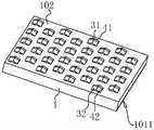
基于上述相关技术的情况,为了减少导光板的光损,使得光线能够均匀分布于导光板的出光面101,并且提高导光板的出光亮度,本申请公开一种导光板的网点结构。参见图2,导光板本体1由PMMA材料制得,也可以由PC材料或PS材料制得。导光板本体1的网点面102上设置有若干网点结构2,若干网点结构2随机排布于导光板的网点面102上,该网点结构2为异形结构。Based on the above-mentioned related art, in order to reduce the light loss of the light guide plate, make the light evenly distributed on the
实施例1:Example 1:
参见图2和图3,导光板的网点结构2包括第一受光面3、第二受光面4以及若干第一连接面5。第一受光面3、第二受光面4以及第一连接面5均为平面,且第一受光面3、第二受光面4均为长方形。第一受光面3的一侧边与第二受光面4的一侧边相互连接并形成夹角,第一受光面3背离第二受光面4的侧边与导光板的网点面102连接并形成夹角,第二受光面4远离第一受光面3的侧边与导光板本体1的网点面102连接并形成夹角。第一受光面3与第二受光面4的另外两侧边分别通过第一连接面5与网点面102连接。在一种实施方式中,第一受光面3和第二受光面4的面积相等,在其他实施方式,第二受光面4的面积也可设置为大于第一受光面3的面积,以使得第二受光面4能接收更多的入射光线并将更多的入射光线反射至导光板本体1的出光面101上,由此提高导光板的出光亮度。Referring to FIGS. 2 and 3 , the
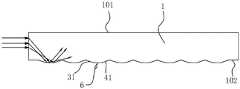
参见图4,第一受光面3的一侧自网点面102沿朝向第二受光面4的方向呈倾斜设置。为了进一步提高导光板的出光亮度,第一受光面3与网点面102的夹角为锐角。为方便理解,将第一受光面3与网点面102的夹角设置为a1,夹角a1的范围可进一步优选为10°-60°,这样设置有利于提高反射光线的扩散范围。将第一受光面3与第二受光面4的夹角设置为b1,夹角b1的范围为60°-170°。将第二受光面4与网点面102的夹角设置为a2,夹角a2范围可进一步优选为10°-60°。在本实施例中,夹角a1优选为30°,夹角b1优选为140°,这样设置一方面使得第二受光面4能够对直接射向出光侧处的光线起到指向性引导的作用,有利于使得更多的光线能反射至出光面101,因此有利于提高亮度,另一方面,第二受光面4使得入射光线能够反射至出光面101靠近出光侧的位置,有利于将反射的光线能均匀分布在出光面101上。Referring to FIG. 4 , one side of the first light-receiving
在一种实施方式中,如图4所示,为方便理解,在网点面102与第一受光面3的连接处设置有分割线L1,分割线L1将夹角a1划分为两个子角,当两个子角的角度大小相等时,夹角a1对称式夹角;当两个子角的角度大小不相等时,夹角a1非对称式夹角,同理可得,夹角a2可以为对称式夹角或非对称式夹角。In one embodiment, as shown in FIG. 4 , for the convenience of understanding, a dividing line L1 is set at the connection between the
在一实施方式中,如图4所示,为方便理解,在第二受光面4与第一受光面3的连接处设置有分割线L2,分割线L2将夹角b1划分为两个子角,当两个子角的角度大小相等时,以使得夹角b1对称式夹角;当两个子角的角度大小不相等时,夹角b1非对称式夹角。In one embodiment, as shown in FIG. 4 , for the convenience of understanding, a dividing line L2 is provided at the connection between the second light-receiving
在一种实施方式中,导光板本体1的出光面101上开设有多个切槽1011,切槽1011为V形切槽1011,经过网点结构2反射后的光线反射至出光面101的V形切槽1011处,V形切槽1011在此改变反射光的传导方向,使得导光板出光更均匀。In one embodiment, the light-emitting
在另一种实施方式中,导光板的出光面101上的切槽1011为半弧形切槽1011,经过网点结构2反射后的光线反射至出光面101的半弧形切槽1011的槽壁处,使得反射光沿着半弧形槽的弧度方向出射,使得导光板出光更柔和。In another embodiment, the
实施例2:Example 2:
本实施例与实施例1的区别在于:参见图5和图6,第一受光面3包括相互连接的第一受光子面31以及第二受光子面32,第一受光子面31以及第二受光子面32的设置有利于增大光线的反射角度的范围。第二受光面4包括相互连接的第三受光子面41以及第四受光子面42,一方面从多个角度对从导光板的出光侧射出的光线起到指向性引导的作用,以减少光线直接从导光板的出光侧射出,从而降低导光板的光损,另一方面有利于使得入射光线能够更均匀地反射到导光板的出光面101处。第一受光子面31的侧边与第三受光子面41的侧边相连接,第二受光子面32的侧边与第四受光子面42的侧边相连接。第一受光子面31的侧边、第二受光子面32的侧边、第三受光子面41的侧边以及第四受光子面42的侧边分别通过第一连接面5与网点面102连接。The difference between this embodiment and
第一受光子面31与第二受光子面32之间的夹角范围为60°-170°,第一受光子面31与第二受光子面32的夹角优选为140°;第三受光子面41与第四受光子面42之间的夹角范围为60°-170°,第三受光子面41与第四受光子面42之间的夹角优选为140°,第一受光子面31与第三受光子面41之间的夹角优选为140°,第二受光子面32与第四受光子面42之间的夹角优选为140°。The included angle between the first light-receiving
如图6和图7,图7是网点结构2做了简略显示处理时所示的光路图,第一受光子面31与第二受光子面32连接并形成范围为60°-170°的夹角,第三受光子面41与第四受光子面42连接并形成范围为60°-170°的夹角,使得第一受光子面31、第二受光子面32、第三受光子面41以及第四受光子面42组合形成具有收拢光线的结构,有利于进一步将入射的光线收拢,以降低入射的光线直接从导光板的出光侧穿出的可能性。Figure 6 and Figure 7, Figure 7 is the light path diagram shown when the
参见图8和图9,为了进一步增大网点结构2的受光面积,第一受光子面31设有第一侧边311,第二受光子面32设有第二侧边321,第三受光子面41设置有第三侧边411,第四受光子面42设置有第四侧边421,第一侧边311、第二侧边321、第三侧边411以及第四侧边421组合形成第三受光面6,第三受光面6正投影于网点面102的形状为正方形。第三受光面6为平面。8 and 9, in order to further increase the light-receiving area of the
图10(网点结构2做了简略显示处理)显示的是含有第三受光面6时网点结构2的光路,第三受光面6与第二受光面4配合将更多的入射光进行反射,有利于进一步提升导光板的出光亮度。Figure 10 (the
在其他实施方式中,参见图11和图12,第一受光子面31、第二受光子面32、第三受光子面41以及第四受光子面42的形状也可以为三角形,这样设置能够同样达到进一步提升导光板的出光亮度的效果。In other embodiments, referring to FIG. 11 and FIG. 12 , the shapes of the
实施例3:Example 3:
本实施例与实施例1的区别在于:参见图13和图14,第一连接面5、第一受光面3以及第二受光面4均为曲面,在保证对朝向出光侧射出的入射光起到指向性引导作用的条件下,这样设置有利于使得第一受光面3以及第二受光面4接受到的入射光,因此能使更多的光线反射至导光板的出光面101。The difference between this embodiment and
图15显示的是本实施例中网点结构2的光路图,第一受光面3与第二受光面4连接形成朝向出光面101的方向凸出的曲面,由于第一受光面3与第二受光面4配合朝向出光面101的方向凸出,因此达到将更多的入射光均匀地反射至导光板的出光面101上,光线有效利用在有效视区以内,还能够使得入射光经过该曲面的反射后能够从不同的方向射至导光板的出光面101上,由此能够使得导光板的出光面101上的光线更柔和。FIG. 15 shows the optical path diagram of the
在另一种实施方式中,参见图16和图17,基于第一连接面5设置为曲面的结构下,将第一受光面3以及第二受光面4均设置为平面。参见图18,第一受光面3与第二受光面4连接处朝向出光面101的方向凸出并形成夹角c1,在本实施方式中,夹角c1的角度范围为60°-170°,夹角c1可选为60°、70°、80°、90°、100°、110°、120°、130°、135°、140°、145°、150°、155°、160°或170°等,夹角c1大小的改变能够改变光线反射至导光板出光面101的位置,而将夹角c1设置在上述范围内,有利于使得更多的光线能更均匀地反射至导光板出光面101。In another embodiment, referring to FIGS. 16 and 17 , based on the structure in which the first connecting
第一受光面3与第二受光面4连接处朝向出光面101的方向凸出,能够实现接收更多的入射光,同时能够将更多的入射光扩散至导光板的出光面101上,以提高导光板的出光亮度,同时也有利于使得光线能更均匀地分布在导光板的出光面101。The connection between the first light-receiving
本申请实施例还公开一种用于加工上述实施例中的导光板的网点结构的撞针结构,应用于撞点机上,撞点机通过撞针结构通过机械撞击在金属模芯上形成多个凸状网点,以得到带有凸状网点的金属模芯,以便后续能够直接加工出导光板的网点结构2。参见图19,撞针结构包括针杆7和撞点头8,针杆7可拆卸安装于撞点机,以便工作人员加工不同形状的网点结构2。撞点头8包括连接部10以及凸起部9。连接部10的一端与针杆7的一端固定连接,连接部10的另一端用于与凸起部9相连接。撞点头8的最大厚度范围为0.2-0.8mm,撞点头8的最大厚度优选为0.4mm,在有效制作网点结构2的条件下,保证撞点头8的结构强度。凸起部9的厚度范围为0.01-0.02mm,在本实施例中,凸起部9的厚度为0.015mm。凸起部9用于加工网点结构2的部位形状与导光板所需要的网点结构2的形状一一对应。The embodiment of the present application also discloses a striker structure for processing the dot structure of the light guide plate in the above-mentioned embodiments, which is applied to a striker. In order to obtain a metal mold core with convex mesh points, the
在一种实施方式中,参见图19和图20,凸起部9包括第一面91、第二面92以及若干第二连接面93,第一面91、第二面92以及若干第二连接面93均为平面。第一面91的一侧边与第二面92的一侧边相互连接,第一面91背离第二面92的侧边与连接部10侧面的侧边相连接,第二面92远离第一面91的侧边与连接部10另一侧面的侧边相连接;第一面91与第二面92的另外两侧边分别通过第二连接面93与连接部10连接,第一面91与连接部10的侧面夹角为锐角并优选为30°,且第一面91与第二面92之间的夹角的角度范围为60°-170°,且第一面91与第二面92之间的夹角的角度优选为140°。这样设置能够直接加工出对应的网点结构2的形状,节省二次加工步骤,有利于提升导光板的网点结构2的加工效率。In one embodiment, referring to FIGS. 19 and 20 , the raised portion 9 includes a
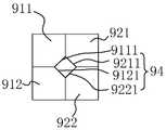
具体的,第一面91包括相互连接的第一子面911以及第二子面912,第二面92包括相互连接的第三子面921以及第四子面922,第一子面911的侧边与第三子面921的侧边相连接,第二子面912的侧边与第四子面922的侧边相连接;第一子面911、第二子面912、第三子面921以及第四子面922分别通过第二连接面93与网点面102连接。Specifically, the
第一子面911与第二子面912之间的夹角的角度范围为60°-170°,第一子面911与第二子面912之间的夹角角度优选为140°。第三子面921与第四子面922之间的夹角的角度范围为60°-170°,第三子面921与第四子面922之间的夹角的角度优选为140°。第一子面911与第三子面921之间的夹角的角度范围为60°-170°并优选为140°,第二子面912与第四子面922之间的夹角的角度范围为60°-170°并优选为140°。The angle range of the included angle between the
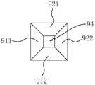
在另一种实施方式中,参见图21和图22,第一子面911设有第一边9111,第二子面912设有第二边9121,第三子面921设置有第三边9211,第四子面922设置有第四边9221,第一边9111、第二边9121、第三边9211以及第四边9221组合形成第三面94,第三面94为平面。In another embodiment, referring to FIGS. 21 and 22 , the
参见图23,第三面94正投影于连接部10的形状为正方形。第一子面911、第二子面912、第三子面921、第四子面922以及第三面94配合形成凸起部9,使得该凸起部9与上述其中一种网点结构2的形状一一对应,在后续撞点加工中,能够对金属模芯一次撞点成型。Referring to FIG. 23 , the shape of the orthographic projection of the
在另一种实施方式中,参见图24,第一子面911、第二子面912、第三子面921以及第四子面922的形状也可以为三角形,这样设置能够同样达到进一步提升导光板的出光亮度的效果。In another embodiment, referring to FIG. 24 , the shapes of the
在另一种实施方式中,参见图25,第二连接面93为曲面,第一面91以及第二面92均为平面,且第一面91与第二面92连接处朝向连接部10的方向突出并形成夹角d1,且夹角d1的角度范围为60°-170°。In another embodiment, referring to FIG. 25 , the
在另一种实施方式中,参见图26,第二连接面93、第一面91以及第二面92均为曲面,且第一面91与第二面92连接形成朝向连接部10的方向凸出的曲面,这样设置一方面能够实现配合加工对应的网点结构2,另一方面有利于节省对网点结构2进行二次抛光打磨的工序,有利于提高导光板网点结构2的加工效率。In another embodiment, referring to FIG. 26 , the second connecting
本申请实施例还公开一种用于加工上述任一项实施例中的导光板网点结构的撞点工艺,通过撞点机或其他能够实现撞点功能的设备来实现加工导光板的网点结构2,网点结构2与撞针结构中的凸起部9一一对应。撞点工艺包括:The embodiment of the present application also discloses a dot-strike process for processing the dot structure of the light guide plate in any of the above-mentioned embodiments. The dot-
S1、采用上述任一项实施方式中的撞针结构通过机械撞击在金属模芯上形成多个凸状网点,以得到带有凸状网点的金属模芯。S1. Using the striker structure in any of the above embodiments, a plurality of convex mesh points are formed on the metal mold core by mechanical impact, so as to obtain a metal mold core with convex mesh points.
S2、采用金属模芯通过注塑成型或热压成型以将金属模芯上的凸状网点转写至导光板本体1的网点面102,制得具有网点结构2的导光板。S2. Using a metal mold core to transfer the convex mesh points on the metal mold core to the
先采用上述实施例中的撞针结构来制得金属模芯,使得金属模芯具有凸状网点,再采用金属模芯将凸状网点转写至导光板本体1上,使得导光板本体1的网点面102上形成多个网点结构2,实现加工形成带有网点结构2的导光板。First, the striker structure in the above embodiment is used to prepare the metal mold core, so that the metal mold core has convex mesh points, and then the metal mold core is used to transfer the convex mesh points to the light
以上均为本申请的较佳实施例,并非依此限制本申请的保护范围,故:凡依本申请的结构、形状、原理所做的等效变化,均应涵盖于本申请的保护范围之内。The above are all preferred embodiments of the present application, and are not intended to limit the protection scope of the present application. Therefore: all equivalent changes made according to the structure, shape and principle of the present application should be covered within the scope of the present application. Inside.
Claims (8)
Priority Applications (1)
| Application Number | Priority Date | Filing Date | Title |
|---|---|---|---|
| CN202111164079.8ACN113805268B (en) | 2021-09-30 | 2021-09-30 | Dot structure, striker structure and striker process of a light guide plate |
Applications Claiming Priority (1)
| Application Number | Priority Date | Filing Date | Title |
|---|---|---|---|
| CN202111164079.8ACN113805268B (en) | 2021-09-30 | 2021-09-30 | Dot structure, striker structure and striker process of a light guide plate |
Publications (2)
| Publication Number | Publication Date |
|---|---|
| CN113805268A CN113805268A (en) | 2021-12-17 |
| CN113805268Btrue CN113805268B (en) | 2022-10-18 |
Family
ID=78897281
Family Applications (1)
| Application Number | Title | Priority Date | Filing Date |
|---|---|---|---|
| CN202111164079.8AActiveCN113805268B (en) | 2021-09-30 | 2021-09-30 | Dot structure, striker structure and striker process of a light guide plate |
Country Status (1)
| Country | Link |
|---|---|
| CN (1) | CN113805268B (en) |
Citations (2)
| Publication number | Priority date | Publication date | Assignee | Title |
|---|---|---|---|---|
| CN101059580A (en)* | 2006-04-20 | 2007-10-24 | 胜华科技股份有限公司 | Arrangement structure of light guide plate, light guide unit and surface light source device |
| CN112799169A (en)* | 2021-02-04 | 2021-05-14 | 东莞市元立电子科技有限公司 | A new type of light guide plate with high brightness and high concealment |
Family Cites Families (9)
| Publication number | Priority date | Publication date | Assignee | Title |
|---|---|---|---|---|
| US6712481B2 (en)* | 1995-06-27 | 2004-03-30 | Solid State Opto Limited | Light emitting panel assemblies |
| CN104375236B (en)* | 2014-11-26 | 2017-10-24 | 深圳市华星光电技术有限公司 | Light guide plate, backlight module and display |
| CN106054310A (en)* | 2016-08-16 | 2016-10-26 | 京东方科技集团股份有限公司 | Light guide plate, backlight module group, display device, RBI machine, and control method for RBI machine |
| CN206096531U (en)* | 2016-08-16 | 2017-04-12 | 京东方科技集团股份有限公司 | Light guide plate, backlight unit , display device and hit some machines |
| CN207882482U (en)* | 2018-03-07 | 2018-09-18 | 瑞仪光电(苏州)有限公司 | Leaded light component, backlight module and display equipment |
| CN111413760A (en)* | 2019-01-07 | 2020-07-14 | 杨宏 | Light guide body mesh point structure, light guide body, mold, backlight structure and display device |
| CN209821424U (en)* | 2019-06-28 | 2019-12-20 | 东莞市钰晟电子科技有限公司 | Novel light guide plate with lattice point structure |
| CN211348691U (en)* | 2019-09-30 | 2020-08-25 | 苏州天禄光科技股份有限公司 | Light guide plate mesh point and light guide plate |
| CN212808683U (en)* | 2020-06-17 | 2021-03-26 | 深圳市隆利科技股份有限公司 | Special-shaped screen point for improving brightness |
- 2021
- 2021-09-30CNCN202111164079.8Apatent/CN113805268B/enactiveActive
Patent Citations (2)
| Publication number | Priority date | Publication date | Assignee | Title |
|---|---|---|---|---|
| CN101059580A (en)* | 2006-04-20 | 2007-10-24 | 胜华科技股份有限公司 | Arrangement structure of light guide plate, light guide unit and surface light source device |
| CN112799169A (en)* | 2021-02-04 | 2021-05-14 | 东莞市元立电子科技有限公司 | A new type of light guide plate with high brightness and high concealment |
Also Published As
| Publication number | Publication date |
|---|---|
| CN113805268A (en) | 2021-12-17 |
Similar Documents
| Publication | Publication Date | Title |
|---|---|---|
| TWI296694B (en) | ||
| CN103375741B (en) | Light guide plate and backlight module using same | |
| CN112799169B (en) | High-brightness high-concealing light guide plate | |
| JP2005071610A (en) | Light guide plate and plane light source device | |
| TW201000974A (en) | Light guide plate, surface illumination device, liquid crystal display device, and manufacturing method for the light guide plate | |
| JP2002197908A (en) | Light control sheet, surface light source device, and liquid crystal display | |
| KR20130117645A (en) | Light-guide panel, planar light-source device, and display device | |
| US8333497B2 (en) | Light guide plate having micro structures arranged in geometric and stripe patterns | |
| JP2021532530A (en) | Light guide plate, backlight module and display device | |
| JP2013187059A (en) | Light guide plate, and planar light source device | |
| CN104620041A (en) | Planar light source device and display device using same | |
| JP2004006326A (en) | Surface light source device and light guide used therein | |
| JP4172008B2 (en) | Surface light source device | |
| US8870434B2 (en) | Asymmetric serrated edge light guide film having circular base segments | |
| CN104765095A (en) | Light guide plate and light source module | |
| TW200530632A (en) | Grid structure of light guide plate | |
| CN113805268B (en) | Dot structure, striker structure and striker process of a light guide plate | |
| CN112965161B (en) | Light guide plate and dot arrangement method thereof | |
| CN207946553U (en) | Light guide plate and backlight module | |
| JPH11329039A (en) | Surface light source device | |
| CN214174666U (en) | Novel high-brightness high-concealing light guide plate | |
| CN215575757U (en) | A light guide plate and striker structure | |
| CN114217374B (en) | A light guide plate with improved brightness | |
| CN215895017U (en) | Light guide plate with brightness improvement | |
| CN110333569A (en) | Light guide plate and manufacturing method thereof |
Legal Events
| Date | Code | Title | Description |
|---|---|---|---|
| PB01 | Publication | ||
| PB01 | Publication | ||
| SE01 | Entry into force of request for substantive examination | ||
| SE01 | Entry into force of request for substantive examination | ||
| GR01 | Patent grant | ||
| GR01 | Patent grant | ||
| CP03 | Change of name, title or address | ||
| CP03 | Change of name, title or address | Address after:523000, No. 682 Xiecao Road, Xiegang Town, Dongguan City, Guangdong Province Patentee after:Dongguan Yuanli Optoelectronics Co.,Ltd. Country or region after:China Address before:523900 No.1, Xingye North Road, shanghuan, Shuanggang community, Houjie Town, Dongguan City, Guangdong Province Patentee before:DONGGUAN YUANLI ELECTRONIC TECHNOLOGY Co.,Ltd. Country or region before:China |