CN113790492B - Trombe wall with partially covered photovoltaic and thermocatalytic combination - Google Patents
Trombe wall with partially covered photovoltaic and thermocatalytic combinationDownload PDFInfo
- Publication number
- CN113790492B CN113790492BCN202111117985.2ACN202111117985ACN113790492BCN 113790492 BCN113790492 BCN 113790492BCN 202111117985 ACN202111117985 ACN 202111117985ACN 113790492 BCN113790492 BCN 113790492B
- Authority
- CN
- China
- Prior art keywords
- wall
- heat
- glass plate
- metal heat
- trombe
- Prior art date
- Legal status (The legal status is an assumption and is not a legal conclusion. Google has not performed a legal analysis and makes no representation as to the accuracy of the status listed.)
- Active
Links
- 229910052751metalInorganic materials0.000claimsabstractdescription39
- 239000002184metalSubstances0.000claimsabstractdescription39
- 239000011521glassSubstances0.000claimsabstractdescription36
- 239000003054catalystSubstances0.000claimsabstractdescription28
- 239000011248coating agentSubstances0.000claimsabstractdescription27
- 238000000576coating methodMethods0.000claimsabstractdescription27
- XLYOFNOQVPJJNP-UHFFFAOYSA-NwaterSubstancesOXLYOFNOQVPJJNP-UHFFFAOYSA-N0.000claimsabstractdescription27
- 238000009423ventilationMethods0.000claimsabstractdescription18
- 238000009413insulationMethods0.000claimsabstractdescription13
- 238000006555catalytic reactionMethods0.000claimsabstractdescription7
- 239000000463materialSubstances0.000claimsdescription6
- 229910000314transition metal oxideInorganic materials0.000claimsdescription3
- 239000000853adhesiveSubstances0.000claims1
- 230000001070adhesive effectEffects0.000claims1
- 238000010438heat treatmentMethods0.000abstractdescription16
- 238000010248power generationMethods0.000abstractdescription8
- 238000004887air purificationMethods0.000abstractdescription4
- 230000005540biological transmissionEffects0.000abstractdescription3
- 238000010521absorption reactionMethods0.000abstractdescription2
- 230000009286beneficial effectEffects0.000abstractdescription2
- 238000007254oxidation reactionMethods0.000description9
- 230000003197catalytic effectEffects0.000description8
- 230000000694effectsEffects0.000description7
- 238000005516engineering processMethods0.000description6
- 238000005265energy consumptionMethods0.000description5
- CURLTUGMZLYLDI-UHFFFAOYSA-NCarbon dioxideChemical compoundO=C=OCURLTUGMZLYLDI-UHFFFAOYSA-N0.000description4
- 238000000034methodMethods0.000description4
- 230000005855radiationEffects0.000description4
- OKTJSMMVPCPJKN-UHFFFAOYSA-NCarbonChemical compound[C]OKTJSMMVPCPJKN-UHFFFAOYSA-N0.000description3
- QVGXLLKOCUKJST-UHFFFAOYSA-Natomic oxygenChemical compound[O]QVGXLLKOCUKJST-UHFFFAOYSA-N0.000description3
- 229910052799carbonInorganic materials0.000description3
- 230000003760hair shineEffects0.000description3
- 239000011810insulating materialSubstances0.000description3
- 230000003647oxidationEffects0.000description3
- 230000001590oxidative effectEffects0.000description3
- 229910052760oxygenInorganic materials0.000description3
- 239000001301oxygenSubstances0.000description3
- 239000002957persistent organic pollutantSubstances0.000description3
- 238000000746purificationMethods0.000description3
- 238000002834transmittanceMethods0.000description3
- 239000001569carbon dioxideSubstances0.000description2
- 229910002092carbon dioxideInorganic materials0.000description2
- 238000010276constructionMethods0.000description2
- 238000001816coolingMethods0.000description2
- 238000013461designMethods0.000description2
- 230000009467reductionEffects0.000description2
- 230000009471actionEffects0.000description1
- 238000004378air conditioningMethods0.000description1
- 238000011161developmentMethods0.000description1
- 238000010586diagramMethods0.000description1
- 230000005611electricityEffects0.000description1
- 239000003344environmental pollutantSubstances0.000description1
- 239000003292glueSubstances0.000description1
- 230000006872improvementEffects0.000description1
- 239000012774insulation materialSubstances0.000description1
- 230000010354integrationEffects0.000description1
- 230000007774longtermEffects0.000description1
- 238000012423maintenanceMethods0.000description1
- 238000004519manufacturing processMethods0.000description1
- 238000012986modificationMethods0.000description1
- 230000004048modificationEffects0.000description1
- 239000005416organic matterSubstances0.000description1
- 231100000719pollutantToxicity0.000description1
- 230000008569processEffects0.000description1
- 230000000750progressive effectEffects0.000description1
- 238000005728strengtheningMethods0.000description1
- 238000012546transferMethods0.000description1
Images

Classifications
- F—MECHANICAL ENGINEERING; LIGHTING; HEATING; WEAPONS; BLASTING
- F24—HEATING; RANGES; VENTILATING
- F24F—AIR-CONDITIONING; AIR-HUMIDIFICATION; VENTILATION; USE OF AIR CURRENTS FOR SCREENING
- F24F7/00—Ventilation
- F24F7/003—Ventilation in combination with air cleaning
- B—PERFORMING OPERATIONS; TRANSPORTING
- B01—PHYSICAL OR CHEMICAL PROCESSES OR APPARATUS IN GENERAL
- B01D—SEPARATION
- B01D53/00—Separation of gases or vapours; Recovering vapours of volatile solvents from gases; Chemical or biological purification of waste gases, e.g. engine exhaust gases, smoke, fumes, flue gases, aerosols
- B01D53/34—Chemical or biological purification of waste gases
- B01D53/74—General processes for purification of waste gases; Apparatus or devices specially adapted therefor
- B01D53/86—Catalytic processes
- B01D53/8668—Removing organic compounds not provided for in B01D53/8603 - B01D53/8665
- F—MECHANICAL ENGINEERING; LIGHTING; HEATING; WEAPONS; BLASTING
- F24—HEATING; RANGES; VENTILATING
- F24D—DOMESTIC- OR SPACE-HEATING SYSTEMS, e.g. CENTRAL HEATING SYSTEMS; DOMESTIC HOT-WATER SUPPLY SYSTEMS; ELEMENTS OR COMPONENTS THEREFOR
- F24D15/00—Other domestic- or space-heating systems
- F24D15/02—Other domestic- or space-heating systems consisting of self-contained heating units, e.g. storage heaters
- F—MECHANICAL ENGINEERING; LIGHTING; HEATING; WEAPONS; BLASTING
- F24—HEATING; RANGES; VENTILATING
- F24F—AIR-CONDITIONING; AIR-HUMIDIFICATION; VENTILATION; USE OF AIR CURRENTS FOR SCREENING
- F24F7/00—Ventilation
- F24F7/007—Ventilation with forced flow
- F—MECHANICAL ENGINEERING; LIGHTING; HEATING; WEAPONS; BLASTING
- F24—HEATING; RANGES; VENTILATING
- F24F—AIR-CONDITIONING; AIR-HUMIDIFICATION; VENTILATION; USE OF AIR CURRENTS FOR SCREENING
- F24F8/00—Treatment, e.g. purification, of air supplied to human living or working spaces otherwise than by heating, cooling, humidifying or drying
- F24F8/10—Treatment, e.g. purification, of air supplied to human living or working spaces otherwise than by heating, cooling, humidifying or drying by separation, e.g. by filtering
- F24F8/15—Treatment, e.g. purification, of air supplied to human living or working spaces otherwise than by heating, cooling, humidifying or drying by separation, e.g. by filtering by chemical means
- F24F8/167—Treatment, e.g. purification, of air supplied to human living or working spaces otherwise than by heating, cooling, humidifying or drying by separation, e.g. by filtering by chemical means using catalytic reactions
- F—MECHANICAL ENGINEERING; LIGHTING; HEATING; WEAPONS; BLASTING
- F24—HEATING; RANGES; VENTILATING
- F24V—COLLECTION, PRODUCTION OR USE OF HEAT NOT OTHERWISE PROVIDED FOR
- F24V30/00—Apparatus or devices using heat produced by exothermal chemical reactions other than combustion
- B—PERFORMING OPERATIONS; TRANSPORTING
- B01—PHYSICAL OR CHEMICAL PROCESSES OR APPARATUS IN GENERAL
- B01D—SEPARATION
- B01D2257/00—Components to be removed
- B01D2257/70—Organic compounds not provided for in groups B01D2257/00 - B01D2257/602
- B—PERFORMING OPERATIONS; TRANSPORTING
- B01—PHYSICAL OR CHEMICAL PROCESSES OR APPARATUS IN GENERAL
- B01D—SEPARATION
- B01D2258/00—Sources of waste gases
- B01D2258/06—Polluted air
- Y—GENERAL TAGGING OF NEW TECHNOLOGICAL DEVELOPMENTS; GENERAL TAGGING OF CROSS-SECTIONAL TECHNOLOGIES SPANNING OVER SEVERAL SECTIONS OF THE IPC; TECHNICAL SUBJECTS COVERED BY FORMER USPC CROSS-REFERENCE ART COLLECTIONS [XRACs] AND DIGESTS
- Y02—TECHNOLOGIES OR APPLICATIONS FOR MITIGATION OR ADAPTATION AGAINST CLIMATE CHANGE
- Y02B—CLIMATE CHANGE MITIGATION TECHNOLOGIES RELATED TO BUILDINGS, e.g. HOUSING, HOUSE APPLIANCES OR RELATED END-USER APPLICATIONS
- Y02B10/00—Integration of renewable energy sources in buildings
- Y02B10/10—Photovoltaic [PV]
- Y—GENERAL TAGGING OF NEW TECHNOLOGICAL DEVELOPMENTS; GENERAL TAGGING OF CROSS-SECTIONAL TECHNOLOGIES SPANNING OVER SEVERAL SECTIONS OF THE IPC; TECHNICAL SUBJECTS COVERED BY FORMER USPC CROSS-REFERENCE ART COLLECTIONS [XRACs] AND DIGESTS
- Y02—TECHNOLOGIES OR APPLICATIONS FOR MITIGATION OR ADAPTATION AGAINST CLIMATE CHANGE
- Y02B—CLIMATE CHANGE MITIGATION TECHNOLOGIES RELATED TO BUILDINGS, e.g. HOUSING, HOUSE APPLIANCES OR RELATED END-USER APPLICATIONS
- Y02B10/00—Integration of renewable energy sources in buildings
- Y02B10/20—Solar thermal
Landscapes
- Engineering & Computer Science (AREA)
- Chemical & Material Sciences (AREA)
- Combustion & Propulsion (AREA)
- Mechanical Engineering (AREA)
- General Engineering & Computer Science (AREA)
- Chemical Kinetics & Catalysis (AREA)
- General Chemical & Material Sciences (AREA)
- Physics & Mathematics (AREA)
- Thermal Sciences (AREA)
- Environmental & Geological Engineering (AREA)
- Health & Medical Sciences (AREA)
- Biomedical Technology (AREA)
- Analytical Chemistry (AREA)
- Oil, Petroleum & Natural Gas (AREA)
- Catalysts (AREA)
Abstract
Translated fromChinese
Description
Translated fromChinese技术领域technical field
本发明涉及太阳能建筑一体化技术领域,具体涉及一种部分覆盖式光伏与热催化结合的Trombe墙。The invention relates to the technical field of solar building integration, in particular to a partially covered Trombe wall combining photovoltaic and thermal catalysis.
背景技术Background technique
2020年9月,中国在联合国大会上宣布,将力争于2030年前达到二氧化碳排放峰值,努力争取2060年前实现碳中和,这是中国在巴黎协定之后第一个长期的气候目标,也是第一次提到碳中和。为实现这一目标,需要在节能和减少污染排放等方面继续不懈努力。建筑能耗在中国的能源消耗和碳排放中占据了很大的份额,从建筑物开始建造到结束再到停止使用都会消耗巨大的能量,并且排放出大量的二氧化碳和污染物。另外,近年来人们对居住环境的要求越来越高,室内空调、采暖、通风等实现高质量居住环境的能耗越来越高。而我国土地辽阔,太阳能资源十分丰富,其利用前景十分可观,可以有效地解决人们面对的能源匮乏问题。目前,太阳能建筑一体化技术具有结构简单、成本较低、维护简单等优点,成为建筑行业关注的热点,具有很大的发展潜力。In September 2020, China announced at the United Nations General Assembly that it will strive to reach the peak of carbon dioxide emissions by 2030 and strive to achieve carbon neutrality by 2060. This is China's first long-term climate goal after the Paris Agreement and the first One mention of carbon neutrality. In order to achieve this goal, it is necessary to continue to make unremitting efforts in energy saving and pollution reduction. Building energy consumption accounts for a large share of China's energy consumption and carbon emissions. From the beginning of construction to the end of the building and then to the end of use, a huge amount of energy will be consumed, and a large amount of carbon dioxide and pollutants will be emitted. In addition, in recent years, people have higher and higher requirements on the living environment, and the energy consumption of indoor air conditioning, heating, ventilation, etc. to achieve a high-quality living environment is getting higher and higher. However, my country has a vast land and abundant solar energy resources, and its utilization prospects are very promising, which can effectively solve the energy shortage problem faced by people. At present, building-integrated solar technology has the advantages of simple structure, low cost, and simple maintenance. It has become a hot spot in the construction industry and has great development potential.
Trombe墙是一种被动式太阳能采暖结构,这种功能性的墙体结构可以将太阳能转换为热能,从而实现室内的供暖和通风,提升室内舒适性。除此之外,Trombe的输入能量除了太阳能以外没有其它能量输入,因此将Trombe墙应用在建筑上可以有效地降低室内采暖和通风所需的能耗。但是,传统型Trombe墙仅将太阳能转化为热能并且仅用于采暖,太阳能的利用效率相对较低且功能单一。为此有人提出了在Trombe墙内直接外置、中置、内置太阳能光伏电池板,即集光伏发电和采暖通风为一体的Trombe墙结构,从而实现Trombe墙的多功能化,但这些Trombe墙的功能和太阳能利用效果仍有很大的提升潜力,特别是在夏季运行模式时,存在运行经济性较差的问题。The Trombe wall is a passive solar heating structure. This functional wall structure can convert solar energy into heat energy, thereby realizing indoor heating and ventilation, and improving indoor comfort. In addition, Trombe's input energy has no other energy input except solar energy, so applying Trombe walls to buildings can effectively reduce the energy consumption required for indoor heating and ventilation. However, the traditional Trombe wall only converts solar energy into thermal energy and is only used for heating, and the utilization efficiency of solar energy is relatively low and its function is single. For this reason, someone proposed to directly install external, central, and built-in solar photovoltaic panels in the Trombe wall, that is, a Trombe wall structure integrating photovoltaic power generation and heating and ventilation, so as to realize the multifunctionality of the Trombe wall, but these Trombe walls There is still great potential for improvement in terms of functions and solar energy utilization effects, especially in the summer operation mode, which has the problem of poor operating economy.
热催化氧化技术通过在太阳光的照射下,热催化剂表面产生的晶格氧具有较强的氧化性,可以有效降解室内的有机污染物,达到净化室内空气的目的。在净化室内空气技术领域方面热催化氧化技术具有较好的应用前景。将太阳能作为驱动热催化氧化反应的能量可以避免额外的能源消耗,降低了空气净化的成本,符合节能减排的要求。Thermal catalytic oxidation technology can effectively degrade indoor organic pollutants and achieve the purpose of purifying indoor air through the lattice oxygen generated on the surface of the thermal catalyst under the irradiation of sunlight, which has strong oxidizing properties. In the field of indoor air purification technology, thermal catalytic oxidation technology has a good application prospect. Using solar energy as the energy to drive the thermal catalytic oxidation reaction can avoid additional energy consumption, reduce the cost of air purification, and meet the requirements of energy saving and emission reduction.
因此,如何提供一种绿色、高效、多级利用太阳能的基于光伏发电技术和热催化氧化技术的多功能太阳能集热墙是本领域技术人员亟需解决的问题。Therefore, how to provide a multi-functional solar heat collecting wall based on photovoltaic power generation technology and thermal catalytic oxidation technology, which is green, efficient, and multi-level utilization of solar energy, is an urgent problem to be solved by those skilled in the art.
发明内容Contents of the invention
本发明的目的在于,针对现有技术的不足,提供一种能量利用率高,且夏季时可回收多余热量的部分覆盖式光伏与热催化结合的Trombe墙。The object of the present invention is to provide a partially covered photovoltaic and thermal catalysis Trombe wall with high energy utilization rate and the ability to recover excess heat in summer.
本发明采用的技术方案为:一种部分覆盖式光伏与热催化结合的Trombe墙,所述Trombe墙设置在朝南的墙体内,且与屋顶和地板之间留有间隙;所述Trombe墙包括高透光玻璃板、外侧面附着有热催化剂涂层A的金属吸热板、蛇形管和绝热墙体;所述高透光玻璃板倾斜布置,其上端向室内方向倾斜;所述高透光玻璃板的顶部与屋顶之间的空间形成室外顶部通风口,高透光玻璃板的底部与地板之间的空间形成室外底部通风口;所述高透光玻璃板内嵌有若干太阳能光伏电池模块,太阳能光伏电池模块的内侧面负载热催化剂涂层C;所述金属吸热板和绝热墙体竖直且相邻布置,所述金属吸热板的外侧面与高透光玻璃板的内侧面之间形成空气流道,金属吸热板的内侧面与安装在绝热墙体内蛇形管紧贴;所述绝热墙体的顶面与屋顶之间的空间形成室内顶部通风口,绝热墙体的底面与地板之间的空间形成室内底部通风口,各通风口均分别与空气流道连通。The technical solution adopted in the present invention is: a partially covered Trombe wall combined with photovoltaic and thermal catalysis, the Trombe wall is arranged in the wall facing south, and there is a gap between the roof and the floor; the Trombe wall It includes a high-transmittance glass plate, a metal heat-absorbing plate with a thermal catalyst coating A attached to the outer surface, a serpentine tube, and a heat-insulating wall; the high-transparency glass plate is arranged obliquely, and its upper end is inclined toward the indoor direction; the high The space between the top of the light-transmitting glass plate and the roof forms an outdoor top vent, and the space between the bottom of the high-transparency glass plate and the floor forms an outdoor bottom vent; the high-transparency glass plate is embedded with a number of solar photovoltaic The battery module, the inner side of the solar photovoltaic cell module is loaded with a thermal catalyst coating C; the metal heat absorbing plate and the heat insulating wall are vertically and adjacently arranged, and the outer side of the metal heat absorbing plate is connected to the high light transmittance glass plate An air flow channel is formed between the inner surfaces, and the inner surface of the metal heat-absorbing plate is closely attached to the serpentine pipe installed in the heat-insulating wall; the space between the top surface of the heat-insulating wall and the roof forms an indoor top vent, and the heat-insulating The space between the bottom surface of the wall body and the floor forms indoor bottom ventilation openings, and each ventilation opening is respectively communicated with the air flow channel.
按上述方案,所述绝热墙体的顶面和底面均为截面呈二次贝塞尔曲线状的曲面,绝热墙体的顶面向屋顶方向凸起,绝热墙体的底面向地板方向凸起。According to the above solution, the top surface and the bottom surface of the heat insulating wall body are curved surfaces with a quadratic Bezier curve in section, the top face of the heat insulating wall body protrudes toward the roof, and the bottom face of the heat insulating wall body protrudes toward the floor direction.
按上述方案,所述高透光玻璃板与竖直方向的夹角为4°~6°。According to the above scheme, the included angle between the high light-transmitting glass plate and the vertical direction is 4°-6°.
按上述方案,所述金属吸热板的外侧面设有竖直肋片,竖直肋片的上下两端均与金属吸热板平齐,且竖直肋片的制作材料和金属吸热板的制作材料相同;所述竖直肋片的外侧面负载有热催化剂涂层B。According to the above scheme, the outer surface of the metal heat-absorbing plate is provided with vertical fins, the upper and lower ends of the vertical fins are flush with the metal heat-absorbing plate, and the material of the vertical fins and the metal heat-absorbing plate The materials used are the same; the outer side of the vertical fins is loaded with a thermal catalyst coating B.
按上述方案,所述蛇形管的侧部通过导热胶与金属吸热板连接以减小接触热阻;蛇形管的上下层之间采用绝热材料填充;蛇形管的进水口位于蛇形管的下端,蛇形管的出水口位于蛇形管的上端。According to the above scheme, the side of the serpentine pipe is connected with the metal heat absorbing plate through thermal conductive glue to reduce the contact thermal resistance; the upper and lower layers of the serpentine pipe are filled with heat insulating material; the water inlet of the serpentine pipe is located in the The lower end of the pipe, the water outlet of the serpentine pipe is located at the upper end of the serpentine pipe.
按上述方案,所述太阳能光伏电池模块阵列布置,太阳能光伏电池模块在高透光玻璃板上的覆盖率为0.5~0.7。According to the above proposal, the solar photovoltaic cell modules are arranged in an array, and the coverage ratio of the solar photovoltaic cell modules on the high light-transmitting glass plate is 0.5-0.7.
按上述方案,在所述室外顶部通风口的上方设有室外顶部挡板,室外顶部挡板活动连接在屋顶端部;在所述室外底部通风口的下放设有室外顶部挡板,室外底部挡板活动连接在地板上;在所述绝热墙体的顶部内侧活动连接有室内顶部挡板;在所述绝热墙体的底部内侧连接有室内底部挡板;各挡板可翻转,其上下翻转时可打开或关闭对应的通风口。According to the above scheme, an outdoor top baffle is provided above the outdoor top vent, and the outdoor top baffle is movably connected to the end of the roof; an outdoor top baffle is arranged below the outdoor bottom vent, and the outdoor bottom baffle The board is movably connected on the floor; an indoor top baffle is movably connected to the top inner side of the heat insulating wall; an indoor bottom baffle is connected to the bottom inner side of the heat insulating wall; each baffle can be turned over, and when it is turned up and down The corresponding vent can be opened or closed.
按上述方案,各热催化剂涂层均为过渡金属氧化物MnOx-CeO2热催化剂涂层,且厚度均为5μm~20μm。According to the above scheme, each thermal catalyst coating is a transition metal oxide MnOx -CeO2 thermal catalyst coating, and the thickness is 5 μm to 20 μm.
本发明的有益效果为:本发明所述Trombe墙具有采暖、通风、空气净化、发电以及热水供应等多种功能,并且多种功能之间可相互切换,与传统的太阳能集热墙相比,实现高效、多级利用太阳能的目的。具体如下:The beneficial effects of the present invention are: the Trombe wall of the present invention has multiple functions such as heating, ventilation, air purification, power generation and hot water supply, and can switch between multiple functions, compared with traditional solar heat collecting walls , to achieve the purpose of efficient and multi-level utilization of solar energy. details as follows:
1、本发明将太阳能光伏电池模块阵列嵌入高透光玻璃板中,一部分太阳光直接照射在太阳能光伏电池模块上获得电能,太阳能光伏电池模块温度升高,可以加热太阳能光伏电池模块背面的热催化剂涂层,降解空气中的有机物,净化空气;同时部分热能加热空气流道中的空气。1. In the present invention, the array of solar photovoltaic cell modules is embedded in a high-transparency glass plate, and a part of sunlight is directly irradiated on the solar photovoltaic cell module to obtain electric energy. The temperature of the solar photovoltaic cell module rises, which can heat the thermal catalyst on the back of the solar photovoltaic cell module The coating degrades the organic matter in the air and purifies the air; at the same time, part of the heat energy heats the air in the air passage.
2、本发明在空气流道内侧的竖直肋片和金属吸热板表面均负载了热催化剂涂层,在太阳光的照射下,热催化剂涂层达到启动温度后开始降解空气中的有机污染物,从而达到净化室内空气的目的,提高居住环境的舒适性,且竖直肋片的存在可以提高空气热能和净化的效果。2. In the present invention, the thermal catalyst coating is loaded on the vertical fins inside the air flow channel and the surface of the metal heat-absorbing plate. Under the irradiation of sunlight, the thermal catalyst coating starts to degrade the organic pollution in the air after reaching the start-up temperature objects, so as to achieve the purpose of purifying the indoor air and improve the comfort of the living environment, and the existence of the vertical ribs can improve the effect of air heat and purification.
3、本发明在金属吸热板上连接有竖直肋片,金属吸热板背面紧贴蛇形管,蛇形管的周围用绝热材料填充,可提高不同季节下的太阳能综合利用效率。从高透光玻璃板上透过的太阳光照射在竖直肋片和金属吸热板上,竖直肋片和金属吸热板吸热,一部分热量用于热催化氧化反应,一部分热量用来加热空气流道中的空气,剩余部分热量用来加热蛇形管中的循环水,并且附着在金属吸热板上的竖直肋片可以提升热催化反应效果和加热空气流道内空气的效果。3. In the present invention, vertical fins are connected to the metal heat-absorbing plate, the back of the metal heat-absorbing plate is close to the serpentine tube, and the surrounding of the serpentine tube is filled with heat-insulating materials, which can improve the comprehensive utilization efficiency of solar energy in different seasons. The sunlight passing through the high-transmittance glass plate shines on the vertical fins and the metal heat absorbing plate, and the vertical fins and the metal heat absorbing plate absorb heat, part of the heat is used for thermal catalytic oxidation reaction, and part of the heat The air in the air channel is heated, and the remaining part of the heat is used to heat the circulating water in the serpentine tube, and the vertical fins attached to the metal heat absorbing plate can improve the thermal catalytic reaction effect and the effect of heating the air in the air channel.
4、本发明分为夏季运行模式和冬季运行模式。冬季运行模式时,关闭所述室外顶部通风口和所述室外底部通风口,开启所述室内顶部通风口和所述室内底部通风口,关闭蛇形管的进出口,蛇形管内循环水不流动,竖直肋片和金属吸热板吸收的热量主要用来热催化氧化反应和加热空气流道里的空气,加强室内采暖和通风功能,另一部分热量传递给蛇形管内的循环水,在夜晚时蛇形管内的循环水释放热量加热空气流道内的空气实现日夜交替室内供暖,从而实现冬季采暖、通风、净化和发电的功能。夏季运行模式时,开启所述室内底部通风口、所述室内顶部通风口和所述室外顶部通风口,关闭所述室外底部通风口,开启蛇形管的进出口,蛇形管内循环水流动,回收多余的热量,从而实现夏季通风、换气、净化、发电和产生热水的功能,同时通过调整室外顶部挡板和室内顶部挡板的开度可以调节室内通风量的大小和换气次数。4. The present invention is divided into summer operation mode and winter operation mode. In winter operation mode, close the outdoor top vent and the outdoor bottom vent, open the indoor top vent and the indoor bottom vent, close the inlet and outlet of the serpentine pipe, and the circulating water in the serpentine pipe does not flow , the heat absorbed by the vertical fins and the metal heat-absorbing plate is mainly used for thermal catalytic oxidation reaction and heating the air in the air flow channel to enhance the indoor heating and ventilation function, and the other part of the heat is transferred to the circulating water in the serpentine tube, which can be used at night. The circulating water in the serpentine pipe releases heat to heat the air in the air passage to realize the indoor heating alternately day and night, thereby realizing the functions of heating, ventilation, purification and power generation in winter. In the summer operation mode, the indoor bottom vent, the indoor top vent and the outdoor top vent are opened, the outdoor bottom vent is closed, the inlet and outlet of the serpentine pipe are opened, and the circulating water in the serpentine pipe flows, The excess heat is recovered to realize the functions of ventilation, ventilation, purification, power generation and hot water production in summer. At the same time, the size of indoor ventilation and the number of air changes can be adjusted by adjusting the opening of the outdoor top baffle and the indoor top baffle.
5、本发明中的高透光玻璃板倾斜布置,使得整个空气流道呈上窄下宽的直角梯形形状,一方面改善空气流道内空气的流动状况,增加空气的抽吸力和通风量,另一方面使得空气沿流动方向的流速逐渐增加,增强太阳能光伏电池模块背面的冷却效果,进一步使得上下不同位置处的太阳能光伏电池模块温度均匀;同时,绝热墙体顶面和绝热墙体底面为截面呈二次贝塞尔曲线状的曲面,这一设计与高透光玻璃板倾斜布置结合,可有效减小空气流道进口和出口处拐角的回流漩涡,减小了空气流动阻力,改善了整个空气流道内空气的流动状况,提高了整个系统的性能。5. The high light-transmitting glass plates in the present invention are arranged obliquely, so that the entire air flow channel is in the shape of a right-angled trapezoid with a narrow top and a wide bottom. On the other hand, the flow velocity of the air along the flow direction is gradually increased, the cooling effect on the back of the solar photovoltaic cell module is enhanced, and the temperature of the solar photovoltaic cell module at different positions up and down is further made uniform; at the same time, the top surface of the thermal insulation wall and the bottom surface of the thermal insulation wall are The cross-section is a quadratic Bezier curved surface. This design combined with the inclined arrangement of high light-transmitting glass plates can effectively reduce the return vortex at the corners of the inlet and outlet of the air flow channel, reduce the air flow resistance, and improve the The flow of air in the entire air channel improves the performance of the entire system.
附图说明Description of drawings
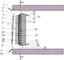
图1为本发明一个具体实施例的结构示意图。Fig. 1 is a structural schematic diagram of a specific embodiment of the present invention.
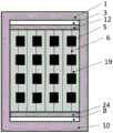
图2为本实施例的左视图。Fig. 2 is the left side view of this embodiment.
图3为图1的A-A剖视图。Fig. 3 is a sectional view along line A-A of Fig. 1 .
其中:1—屋顶;2—室外顶部挡板;3—室外顶部通风口;4—高透光玻璃板;5—太阳能光伏电池模块;6—竖直肋片;7—空气流道;8—室外底部通风口;9—室外底部挡板;10—地板;11—室内顶部通风口;12—绝热墙体顶面;13—室内顶部挡板;14—出水口;15—蛇形管;16—绝热材料;17—绝热墙体;18—热催化剂涂层A;19—金属吸热板;20—热催化剂涂层B;21—热催化剂涂层C;22—进水口;23—室内底部挡板;24—绝热墙体底面;25—室内底部通风口。Among them: 1—roof; 2—outdoor top baffle; 3—outdoor top vent; 4—high light transmission glass plate; 5—solar photovoltaic cell module; 6—vertical fin; 7—air flow channel; 8— Outdoor bottom vent; 9—outdoor bottom baffle; 10—floor; 11—indoor top vent; 12—top surface of thermal insulation wall; 13—indoor top baffle; 14—water outlet; 15—serpentine pipe; 16 —insulation material; 17—insulation wall; 18—thermal catalyst coating A; 19—metal heat absorbing plate; 20—thermal catalyst coating B; 21—thermal catalyst coating C; 22—water inlet; 23—indoor bottom Baffle plate; 24—the bottom surface of the heat-insulating wall; 25—ventilation opening at the bottom of the room.
具体实施方式Detailed ways
下面将结合本发明实例中的附图,对本发明实施例中的技术方案进行清楚、完整地描述,显然,所描述的实施例仅仅是本发明一部分实施例,而不是全部的实施例。基于本发明中的实施例,本领域普通技术人员在没有做出创造性劳动前提下所获得的所有其他实施例,都属于本发明保护的范围。The technical solutions in the embodiments of the present invention will be clearly and completely described below in conjunction with the accompanying drawings in the examples of the present invention. Obviously, the described embodiments are only some of the embodiments of the present invention, not all of them. Based on the embodiments of the present invention, all other embodiments obtained by persons of ordinary skill in the art without making creative efforts belong to the protection scope of the present invention.
如图1所示的一种部分覆盖式光伏与热催化结合的Trombe墙,所述Trombe墙设置在朝南的墙体内,且与屋顶1和地板10之间留有间隙;所述Trombe墙包括高透光玻璃板4、外侧面附着有热催化剂涂层A18的金属吸热板19、蛇形管15和绝热墙体17;所述高透光玻璃板4倾斜布置,其上端向室内方向倾斜;所述高透光玻璃板4的顶部与屋顶1之间的空间形成室外顶部通风口3,高透光玻璃板4的底部与地板10之间的空间形成室外底部通风口8;所述高透光玻璃板4内嵌有若干太阳能光伏电池模块5,太阳能光伏电池模块5的内侧面负载热催化剂涂层C21;所述金属吸热板19和绝热墙体17竖直且相邻布置,所述金属吸热板19的外侧面与高透光玻璃板4的内侧面之间形成空气流道7,金属吸热板19的内侧面与安装在绝热墙体17内蛇形管15紧贴;所述绝热墙体17的顶面12与屋顶1之间的空间形成室内顶部通风口11,绝热墙体17的底面24与地板10之间的空间形成室内底部通风口25,各通风口均分别与空气流道7连通。As shown in Figure 1, a partially covered photovoltaic and thermal catalysis combined Trombe wall, the Trombe wall is arranged in the wall facing south, and there is a gap between the
优选地,所述绝热墙体17的顶面12和底面24均为截面呈二次贝塞尔曲线状的曲面,其中,绝热墙体17的顶面12向屋顶1方向凸起,绝热墙体17的底面24向地板10方向凸起,这一设计减小了空气流道7进口和出口处拐角的回流漩涡,改善了整个空气流道7内空气的流动状况。Preferably, both the
优选地,所述高透光玻璃板4与竖直方向的夹角为4°~6°。高透光玻璃板4倾斜布置,整个空气流道7呈上窄下宽的直角梯形形状,一方面改善了空气流道7内空气的流动状况,增强了空气的抽吸力和通风量,另一方面使得空气沿流动方向的流速逐渐增加,提高了太阳能光伏电池模块5背面的冷却效果,进一步使得上下不同位置处的太阳能光伏电池模块5温度均匀。Preferably, the included angle between the high light-transmitting
优选地,如图2所示,所述太阳能光伏电池模块5阵列布置,太阳能光伏电池模块5在高透光玻璃板4上的覆盖率为0.5~0.7。太阳能光伏电池模块5的寿命和发电效率与太阳能光伏电池模块5的温度有关,温度越高效率越低;本发明中,太阳能光伏电池模块5背面的热催化剂涂层C21利用太阳能光伏电池模块5产生的热能进行催化反应,并将产生的热能加热空气流道7中的空气,从而使得太阳能光伏电池模块5的温度降低,可提高太阳能光伏电池模块5的发电效率,延长了太阳能光伏电池模块5的使用寿命。Preferably, as shown in FIG. 2 , the solar
优选地,所述金属吸热板19的外侧面设有竖直肋片6,竖直肋片6的上下两端均与金属吸热板19平齐,且竖直肋片6的制作材料和金属吸热板19的制作材料相同;所述竖直肋片6的外侧面负载有热催化剂涂层B20。Preferably, the outer surface of the metal
优选地,所述蛇形管15位于金属吸热板19侧的绝热墙体17内,如图3所示,蛇形管15的侧部通过导热胶与金属吸热板19连接以减小接触热阻;蛇形管15的上下层之间采用绝热材料16填充;蛇形管15的进水口22(也即冷水进口)位于蛇形管15的下端,蛇形管15的出水口14(也即热水出口)位于蛇形管15的上端。Preferably, the
优选地,在所述室外顶部通风口3的上方设有室外顶部挡板2,室外顶部挡板2活动连接在屋顶1端部;在所述室外底部通风口8的下放设有室外顶部挡板2,室外底部挡板9活动连接在地板10上;在所述绝热墙体17的顶部内侧活动连接有室内顶部挡板13;在所述绝热墙体17的底部内侧连接有室内底部挡板23;各挡板可翻转,其上下翻转时可打开或关闭对应的通风口。Preferably, an outdoor
本发明中,各热催化剂涂层均为过渡金属氧化物MnOx-CeO2热催化剂涂层,且厚度均为5μm~20μm。在太阳光的照射下,MnOx-CeO2热催化剂涂层表面产生的晶格氧具有比较强的氧化性,可以用于降解室内的有机污染物,达到净化室内空气的目的。In the present invention, each thermal catalyst coating is a transition metal oxide MnOx -CeO2 thermal catalyst coating, and the thickness is 5 μm to 20 μm. Under the irradiation of sunlight, the lattice oxygen generated on the surface of MnOx -CeO2 thermal catalyst coating has relatively strong oxidizing property, which can be used to degrade indoor organic pollutants and achieve the purpose of purifying indoor air.
本发明中,所述Trombe墙朝南布置,太阳照射时间长。本发明的工作原理如下:In the present invention, the Trombe wall is arranged facing south, and the sun shines for a long time. The working principle of the present invention is as follows:
1、当太阳光照射在高透光玻璃板4上时,一部分太阳光照射在高透光玻璃板4内的太阳能光伏电池模块5上,太阳能光伏电池模块5吸收太阳光后,将小部分太阳辐射能转换为电能,未转换为电能的大部分太阳辐射则转换为热能,使得太阳能光伏电池模块5的温度上升,太阳能光伏电池模块5背面负载的热催化剂涂层C21升温,达到热催化氧化反应的启动温度后,表面会产生具有氧化性的晶格氧,将空气中的有机污染物氧化分解;此外,热催化剂涂层C21升温后多余的热量加热空气流道7中的空气,促进空气流动,达到室内通风的效果;来自外界太阳辐射的另一部分太阳光透过高透光玻璃板4直接照射在表面涂覆有高吸收率的热催化剂涂层的竖直肋片6和金属吸热板19上,竖直肋片6和金属吸热板19以及表面涂覆的热催化剂涂层升温,进行热催化氧化反应,剩余热量一部分用于加热空气流道7中的空气,进一步促进空气流动,另一部分热量则传递给蛇形管15内的循环水。1. When sunlight shines on the high-
2、冬季采暖季节,室外顶部挡板2向下翻转关闭室外顶部通风口3,室外底部挡板9向上翻转关闭室外底部通风口8,室内顶部挡板13向下翻转打开室内顶部通风口11,室内底部挡板23向上翻转打开室内底部通风口25,蛇形管15内通入循环水后关闭其冷源进口和冷源出口,循环水不流动,室内空气从室内底部通风口25进入空气流道7,经过加热、净化过后,由室内顶部通风口11进入室内,为室内进行供暖的同时可以净化室内的空气,还能产生电能,夜晚蛇形管15内的循环水还可以释放热量,实现日夜交替长时间供暖。2. During the winter heating season, the outdoor
3、夏季通风季节,室外底部挡板9向上翻转关闭室外底部通风口8,翻转对应的挡板打开室内底部通风口25、室内顶部通风口11和室外顶部通风口3,并打开蛇形管15的进水口22和出水口14,使蛇形管15内的循环水流动;在太阳辐射的作用下,空气流道7中的空气流动,使得室内空气通过室内底部通风口25进入空气流道7,空气流道7中的空气完成传热过程和热催化氧化反应后,一部分空气从室外顶部通风口3排出,另一部分由室内顶部通风口11进入室内,且两部分空气量分别由室外顶部挡板2和室内底部挡板23的开度进行调整,从而达到强化室内通风、调节室内温度的目的。由于蛇形管15内循环水的存在,可以吸收来自金属吸热板19的热量,从而进一步回收空气流道7中空气的热量,实现热水供应。3. In the summer ventilation season, the
本说明书中各个实施例采用递进的方式描述,每个实施例重点说明的都是与其他实施例的不同之处,各个实施例之间相同相似的部分互相参见即刻。对于实施例公开的装置而言,由于其与实施例公开的方法相对应,所以描述的比较简单,相关之处参见方法部分说明即可。对所公开的实施例的上述说明,使本领域专业技术人员能够实现或使用本发明。对这些实施例的多种修改对本领域的专业技术人员来说将是显而易见的,本文中所定义的一般原理可以在不脱离本发明的精神或范围的情况下,在其它实施例中实现。因此,本发明将不会被限制于本文所示的这些实施例,而是要符合与本文所公开的原理和新颖特点相一致的最宽的范围。Each embodiment in this specification is described in a progressive manner, each embodiment focuses on the differences from other embodiments, and the same and similar parts of each embodiment are referred to immediately. As for the device disclosed in the embodiment, since it corresponds to the method disclosed in the embodiment, the description is relatively simple, and for the related information, please refer to the description of the method part. The above description of the disclosed embodiments is provided to enable any person skilled in the art to make or use the invention. Various modifications to these embodiments will be readily apparent to those skilled in the art, and the general principles defined herein may be implemented in other embodiments without departing from the spirit or scope of the invention. Therefore, the present invention will not be limited to the embodiments shown herein, but is to be accorded the widest scope consistent with the principles and novel features disclosed herein.
Claims (6)
Translated fromChinesePriority Applications (1)
| Application Number | Priority Date | Filing Date | Title |
|---|---|---|---|
| CN202111117985.2ACN113790492B (en) | 2021-09-22 | 2021-09-22 | Trombe wall with partially covered photovoltaic and thermocatalytic combination |
Applications Claiming Priority (1)
| Application Number | Priority Date | Filing Date | Title |
|---|---|---|---|
| CN202111117985.2ACN113790492B (en) | 2021-09-22 | 2021-09-22 | Trombe wall with partially covered photovoltaic and thermocatalytic combination |
Publications (2)
| Publication Number | Publication Date |
|---|---|
| CN113790492A CN113790492A (en) | 2021-12-14 |
| CN113790492Btrue CN113790492B (en) | 2023-04-07 |
Family
ID=79184251
Family Applications (1)
| Application Number | Title | Priority Date | Filing Date |
|---|---|---|---|
| CN202111117985.2AActiveCN113790492B (en) | 2021-09-22 | 2021-09-22 | Trombe wall with partially covered photovoltaic and thermocatalytic combination |
Country Status (1)
| Country | Link |
|---|---|
| CN (1) | CN113790492B (en) |
Families Citing this family (1)
| Publication number | Priority date | Publication date | Assignee | Title |
|---|---|---|---|---|
| CN115627864A (en)* | 2022-09-26 | 2023-01-20 | 北京科技大学 | Metal plate Trombe curtain wall |
Family Cites Families (5)
| Publication number | Priority date | Publication date | Assignee | Title |
|---|---|---|---|---|
| JP4091857B2 (en)* | 2003-02-24 | 2008-05-28 | 有限会社チリウヒーター | Thrombe wall panels |
| CN100547184C (en)* | 2006-11-09 | 2009-10-07 | 中国科学技术大学 | Photovoltaic passive wall heating |
| CN205840051U (en)* | 2016-07-26 | 2016-12-28 | 四川建科智慧节能科技有限公司 | Assembled solar heating combined wall board |
| CN109594677A (en)* | 2018-11-28 | 2019-04-09 | 重庆大学 | A kind of multifunctional solar energy heat collecting wall based on photocatalysis oxidation technique |
| CN112049280A (en)* | 2020-09-11 | 2020-12-08 | 中国科学技术大学 | A catalytic purification - sterilization and disinfection type multifunctional photovoltaic passive ventilation wall |
- 2021
- 2021-09-22CNCN202111117985.2Apatent/CN113790492B/enactiveActive
Also Published As
| Publication number | Publication date |
|---|---|
| CN113790492A (en) | 2021-12-14 |
Similar Documents
| Publication | Publication Date | Title |
|---|---|---|
| CN201129040Y (en) | Energy-saving and environmentally friendly buildings | |
| CN109594677A (en) | A kind of multifunctional solar energy heat collecting wall based on photocatalysis oxidation technique | |
| CN204574540U (en) | A kind of active solar air heat collection system combined with passive type | |
| CN104617863A (en) | Photovoltaic-photocatalytic combination system based on lens condensation principle | |
| CN204494579U (en) | The solar heating integrated with building roof and ventilation energy composite energy system | |
| CN113790492B (en) | Trombe wall with partially covered photovoltaic and thermocatalytic combination | |
| CN211774865U (en) | Energy-conserving photovoltaic curtain system | |
| CN102080431B (en) | Photovoltaic photo-thermal combined hollow glass | |
| CN104935239A (en) | A new type of solar photovoltaic photothermal integrated device | |
| CN207487156U (en) | A kind of solar air heating unit for underground space air circulation | |
| CN201069272Y (en) | A novel solar heat collection plate | |
| CN102353155A (en) | Solar air heat collection device with fluctuant strip fins | |
| CN208075225U (en) | It is a kind of to day thermal-arrest intensified ventilation device | |
| CN201180470Y (en) | Natural Ventilation Solar Photovoltaic Window | |
| CN103196239A (en) | Solar heat collector with ventilation and lighting functions | |
| CN116614082A (en) | Multifunctional solar building integrated component | |
| CN101867320A (en) | Photoelectric-light-thermal combined vacuum straight-through collector tube for trough concentrating system | |
| CN201539024U (en) | A house ventilation system | |
| CN107883431A (en) | A kind of thermoelectricity driving high-efficiency radiator being combined with collecting plate | |
| CN101382325B (en) | Building-integrated solar energy comprehensive heat utilization system | |
| CN205980441U (en) | A photovoltaic curtain wall and waste heat heat pump utilization system based on building envelope | |
| CN209822665U (en) | Photovoltaic and photo-thermal combined plate | |
| CN210772824U (en) | Wave type solar heating device | |
| CN219033681U (en) | A metal sheet Trombe curtain wall | |
| CN202024492U (en) | Solar photovoltaic cogeneration application system |
Legal Events
| Date | Code | Title | Description |
|---|---|---|---|
| PB01 | Publication | ||
| PB01 | Publication | ||
| SE01 | Entry into force of request for substantive examination | ||
| SE01 | Entry into force of request for substantive examination | ||
| GR01 | Patent grant | ||
| GR01 | Patent grant |