CN113790135B - High-power five-cylinder drilling pump set, solid control system and drilling machine - Google Patents
High-power five-cylinder drilling pump set, solid control system and drilling machineDownload PDFInfo
- Publication number
- CN113790135B CN113790135BCN202110726364.8ACN202110726364ACN113790135BCN 113790135 BCN113790135 BCN 113790135BCN 202110726364 ACN202110726364 ACN 202110726364ACN 113790135 BCN113790135 BCN 113790135B
- Authority
- CN
- China
- Prior art keywords
- cylinder
- assembly
- drilling pump
- power
- oil
- Prior art date
- Legal status (The legal status is an assumption and is not a legal conclusion. Google has not performed a legal analysis and makes no representation as to the accuracy of the status listed.)
- Active
Links
Images


Classifications
- F—MECHANICAL ENGINEERING; LIGHTING; HEATING; WEAPONS; BLASTING
- F04—POSITIVE - DISPLACEMENT MACHINES FOR LIQUIDS; PUMPS FOR LIQUIDS OR ELASTIC FLUIDS
- F04B—POSITIVE-DISPLACEMENT MACHINES FOR LIQUIDS; PUMPS
- F04B1/00—Multi-cylinder machines or pumps characterised by number or arrangement of cylinders
- E—FIXED CONSTRUCTIONS
- E21—EARTH OR ROCK DRILLING; MINING
- E21B—EARTH OR ROCK DRILLING; OBTAINING OIL, GAS, WATER, SOLUBLE OR MELTABLE MATERIALS OR A SLURRY OF MINERALS FROM WELLS
- E21B7/00—Special methods or apparatus for drilling
- F—MECHANICAL ENGINEERING; LIGHTING; HEATING; WEAPONS; BLASTING
- F04—POSITIVE - DISPLACEMENT MACHINES FOR LIQUIDS; PUMPS FOR LIQUIDS OR ELASTIC FLUIDS
- F04B—POSITIVE-DISPLACEMENT MACHINES FOR LIQUIDS; PUMPS
- F04B1/00—Multi-cylinder machines or pumps characterised by number or arrangement of cylinders
- F04B1/04—Multi-cylinder machines or pumps characterised by number or arrangement of cylinders having cylinders in star- or fan-arrangement
- F04B1/0404—Details or component parts
- F04B1/0439—Supporting or guiding means for the pistons
- F—MECHANICAL ENGINEERING; LIGHTING; HEATING; WEAPONS; BLASTING
- F04—POSITIVE - DISPLACEMENT MACHINES FOR LIQUIDS; PUMPS FOR LIQUIDS OR ELASTIC FLUIDS
- F04B—POSITIVE-DISPLACEMENT MACHINES FOR LIQUIDS; PUMPS
- F04B1/00—Multi-cylinder machines or pumps characterised by number or arrangement of cylinders
- F04B1/04—Multi-cylinder machines or pumps characterised by number or arrangement of cylinders having cylinders in star- or fan-arrangement
- F04B1/053—Multi-cylinder machines or pumps characterised by number or arrangement of cylinders having cylinders in star- or fan-arrangement with actuating or actuated elements at the inner ends of the cylinders
- F—MECHANICAL ENGINEERING; LIGHTING; HEATING; WEAPONS; BLASTING
- F04—POSITIVE - DISPLACEMENT MACHINES FOR LIQUIDS; PUMPS FOR LIQUIDS OR ELASTIC FLUIDS
- F04B—POSITIVE-DISPLACEMENT MACHINES FOR LIQUIDS; PUMPS
- F04B13/00—Pumps specially modified to deliver fixed or variable measured quantities
- F—MECHANICAL ENGINEERING; LIGHTING; HEATING; WEAPONS; BLASTING
- F04—POSITIVE - DISPLACEMENT MACHINES FOR LIQUIDS; PUMPS FOR LIQUIDS OR ELASTIC FLUIDS
- F04B—POSITIVE-DISPLACEMENT MACHINES FOR LIQUIDS; PUMPS
- F04B17/00—Pumps characterised by combination with, or adaptation to, specific driving engines or motors
- F04B17/03—Pumps characterised by combination with, or adaptation to, specific driving engines or motors driven by electric motors
- F—MECHANICAL ENGINEERING; LIGHTING; HEATING; WEAPONS; BLASTING
- F04—POSITIVE - DISPLACEMENT MACHINES FOR LIQUIDS; PUMPS FOR LIQUIDS OR ELASTIC FLUIDS
- F04B—POSITIVE-DISPLACEMENT MACHINES FOR LIQUIDS; PUMPS
- F04B53/00—Component parts, details or accessories not provided for in, or of interest apart from, groups F04B1/00 - F04B23/00 or F04B39/00 - F04B47/00
- F04B53/08—Cooling; Heating; Preventing freezing
- F—MECHANICAL ENGINEERING; LIGHTING; HEATING; WEAPONS; BLASTING
- F04—POSITIVE - DISPLACEMENT MACHINES FOR LIQUIDS; PUMPS FOR LIQUIDS OR ELASTIC FLUIDS
- F04B—POSITIVE-DISPLACEMENT MACHINES FOR LIQUIDS; PUMPS
- F04B53/00—Component parts, details or accessories not provided for in, or of interest apart from, groups F04B1/00 - F04B23/00 or F04B39/00 - F04B47/00
- F04B53/10—Valves; Arrangement of valves
- F—MECHANICAL ENGINEERING; LIGHTING; HEATING; WEAPONS; BLASTING
- F04—POSITIVE - DISPLACEMENT MACHINES FOR LIQUIDS; PUMPS FOR LIQUIDS OR ELASTIC FLUIDS
- F04B—POSITIVE-DISPLACEMENT MACHINES FOR LIQUIDS; PUMPS
- F04B53/00—Component parts, details or accessories not provided for in, or of interest apart from, groups F04B1/00 - F04B23/00 or F04B39/00 - F04B47/00
- F04B53/16—Casings; Cylinders; Cylinder liners or heads; Fluid connections
- F04B53/162—Adaptations of cylinders
- F—MECHANICAL ENGINEERING; LIGHTING; HEATING; WEAPONS; BLASTING
- F04—POSITIVE - DISPLACEMENT MACHINES FOR LIQUIDS; PUMPS FOR LIQUIDS OR ELASTIC FLUIDS
- F04B—POSITIVE-DISPLACEMENT MACHINES FOR LIQUIDS; PUMPS
- F04B53/00—Component parts, details or accessories not provided for in, or of interest apart from, groups F04B1/00 - F04B23/00 or F04B39/00 - F04B47/00
- F04B53/18—Lubricating
- E—FIXED CONSTRUCTIONS
- E21—EARTH OR ROCK DRILLING; MINING
- E21B—EARTH OR ROCK DRILLING; OBTAINING OIL, GAS, WATER, SOLUBLE OR MELTABLE MATERIALS OR A SLURRY OF MINERALS FROM WELLS
- E21B21/00—Methods or apparatus for flushing boreholes, e.g. by use of exhaust air from motor
- Y—GENERAL TAGGING OF NEW TECHNOLOGICAL DEVELOPMENTS; GENERAL TAGGING OF CROSS-SECTIONAL TECHNOLOGIES SPANNING OVER SEVERAL SECTIONS OF THE IPC; TECHNICAL SUBJECTS COVERED BY FORMER USPC CROSS-REFERENCE ART COLLECTIONS [XRACs] AND DIGESTS
- Y02—TECHNOLOGIES OR APPLICATIONS FOR MITIGATION OR ADAPTATION AGAINST CLIMATE CHANGE
- Y02P—CLIMATE CHANGE MITIGATION TECHNOLOGIES IN THE PRODUCTION OR PROCESSING OF GOODS
- Y02P70/00—Climate change mitigation technologies in the production process for final industrial or consumer products
- Y02P70/10—Greenhouse gas [GHG] capture, material saving, heat recovery or other energy efficient measures, e.g. motor control, characterised by manufacturing processes, e.g. for rolling metal or metal working
Landscapes
- Engineering & Computer Science (AREA)
- Mechanical Engineering (AREA)
- General Engineering & Computer Science (AREA)
- Mining & Mineral Resources (AREA)
- Life Sciences & Earth Sciences (AREA)
- Geology (AREA)
- Fluid Mechanics (AREA)
- Environmental & Geological Engineering (AREA)
- Physics & Mathematics (AREA)
- General Life Sciences & Earth Sciences (AREA)
- Geochemistry & Mineralogy (AREA)
- Details Of Reciprocating Pumps (AREA)
- General Details Of Gearings (AREA)
Abstract
Translated fromChinese
Description
Translated fromChinese技术领域technical field
本发明涉及一种大功率五缸钻井泵组、固控系统及钻机,属于石油钻井装置技术领域。The invention relates to a high-power five-cylinder drilling pump group, a solid control system and a drilling rig, and belongs to the technical field of petroleum drilling devices.
背景技术Background technique
随着当今深井/超深井、高压喷射钻井、大位移水平井、丛式井、海洋平台等新型钻井工艺技术的发展,要求钻井泵往大功率、大排量、高泵压、高可靠性、高效率和轻量化方向发展。目前,在钻井泵本体和驱动电机之间普遍都采用传统的带传动、链传动或齿轮传动等多级传动方式,主要存在以下几方面的缺陷:一是在传动过程中必然存更多在机械损耗,降低了传动效率和工作的可靠性;二是运行维护工作量大,使用成本高;三是体积和重量大,不便于快速运输转场。难以适应越来越高的钻井工艺技术要求。针对这种施工状况,油服企业希望设计制造出一种占地面积小、重量轻、效率高、功率大的钻井泵组,来解决这一生产难题。With the development of new drilling technologies such as deep wells/ultra-deep wells, high-pressure jet drilling, extended-reach horizontal wells, cluster wells, and offshore platforms, drilling pumps are required to have high power, large displacement, high pump pressure, high reliability, Development in the direction of high efficiency and lightweight. At present, traditional multi-stage transmission methods such as belt transmission, chain transmission or gear transmission are generally used between the drilling pump body and the drive motor, and there are mainly defects in the following aspects: First, there must be more machinery in the transmission process. The wear and tear reduces the transmission efficiency and the reliability of work; the second is that the operation and maintenance workload is large, and the use cost is high; the third is that the volume and weight are large, and it is not convenient for rapid transportation and transition. It is difficult to adapt to the increasingly high technical requirements of drilling technology. In response to this construction situation, oil service companies hope to design and manufacture a drilling pump set with a small footprint, light weight, high efficiency, and high power to solve this production problem.
发明内容Contents of the invention
本发明的发明目的在于:针对上述存在的问题,提供一种大功率五缸钻井泵组,该钻井泵组具备结构简单,相对于传统结构其更加紧凑的优势,同时,其也有效的提高了工作效率。The purpose of the present invention is to provide a high-power five-cylinder drilling pump set in view of the above-mentioned problems. work efficiency.
本发明采用的技术方案如下:The technical scheme that the present invention adopts is as follows:
一种大功率五缸钻井泵组,包括底座,所述底座上设置有钻井泵和润滑系统,所述钻井泵包括传动总成、动力端总成以及液力端总成,所述润滑系统包括用于传动总成及动力端总成润滑和冷却的动力端润滑系统,用于液力端总成润滑和冷却的液力端润滑系统;A high-power five-cylinder drilling pump set includes a base on which a drilling pump and a lubrication system are arranged. The drilling pump includes a transmission assembly, a power end assembly and a fluid end assembly. The lubrication system includes Power end lubrication system for lubrication and cooling of transmission assembly and power end assembly, fluid end lubrication system for lubrication and cooling of fluid end assembly;
所述动力端润滑系统包括撬座,所述撬座上设置有润滑油泵,以及用于润滑油过滤的并与润滑油泵连通的过滤器,所述过滤器连通钻井泵,以及连通有用于润滑油冷却的冷却器,所述过滤器设置有温控开关,通过所述温控开关控制润滑油从所述过滤器出来后进入钻井泵进行润滑冷却或者进入冷却器中进行冷却。The power end lubrication system includes a skid, on which a lubricating oil pump is arranged, and a filter used for filtering lubricating oil and communicated with the lubricating oil pump, the filter communicates with the drilling pump, and communicates with a filter for lubricating oil Cooling cooler, the filter is provided with a temperature control switch, through which the lubricating oil is controlled to come out of the filter and then enter the drilling pump for lubrication and cooling or enter the cooler for cooling.
进一步的,所述动力端润滑系统采用风冷或水冷。Further, the power end lubrication system adopts air cooling or water cooling.
进一步的,所述动力端润滑系统包括润滑油的吸入管口和排油管口,所述润滑油泵设置有油泵进油口和油泵出油口,所述吸入管口连通油泵进油口,所述排油管口连通钻井泵;Further, the lubricating system at the power end includes a lubricating oil suction nozzle and an oil discharge nozzle, the lubricating oil pump is provided with an oil pump inlet and an oil pump outlet, the suction nozzle communicates with the oil pump inlet, the The oil discharge pipe port is connected to the drilling pump;
所述过滤器设置有过滤器进油口,所述过滤器进油口连通油泵出油口,所述过滤器还设置有过滤器排油口一和过滤器排油口二,所述过滤器排油口一连通冷却器以用于润滑油冷却,所述过滤器排油口二连通排油管口以用于将润滑油送入到钻井泵当中。The filter is provided with a filter oil inlet, and the filter oil inlet is connected to the oil pump outlet, and the filter is also provided with a filter
进一步的,所述冷却器设置有冷却器进油口和冷却器出油口,所述冷却器进油口连通过滤器排油口一,所述冷却器出油口连通排油管口以实现冷却后的润滑液进入钻井泵。Further, the cooler is provided with a cooler oil inlet and a cooler oil outlet, the cooler oil inlet is connected to the filter oil outlet one, and the cooler oil outlet is connected to the oil outlet pipe to realize cooling The final lubricating fluid enters the drilling pump.
进一步的,所述动力端润滑系统还设置有溢油管路,所述溢油管路通过溢流安全阀组连通系统油路管路,通过溢流安全阀组检测油压以控制润滑油的溢流。Further, the lubrication system at the power end is also provided with an oil overflow pipeline, and the oil overflow pipeline is connected to the oil pipeline of the system through the overflow safety valve group, and the oil pressure is detected through the overflow safety valve group to control the flow of lubricating oil. overflow.
进一步的,所述冷却器包括动力模块、热交换模块和水帘模块,所述动力模块采用空气吸入的方式实现冷却,所述动力模块包括电机以及设置于电机转子上的散热扇叶。Further, the cooler includes a power module, a heat exchange module and a water curtain module, and the power module adopts air suction to achieve cooling, and the power module includes a motor and cooling fan blades arranged on the rotor of the motor.
进一步的,水帘模块包括壳体、散热水帘墙、入水分水管、出水口和积水池,所述壳体设置有冷却水入口,并通过入水分水管接通水源,还包括分水装置,通过分水装置将水均匀的进入散热水帘墙上部。Further, the water curtain module includes a housing, a heat dissipation water curtain wall, a water inlet pipe, a water outlet and a pool, the housing is provided with a cooling water inlet, and is connected to a water source through the water inlet pipe, and also includes a water diversion device , through the water distribution device to evenly enter the water into the upper part of the cooling water curtain wall.
进一步的,所述传动总成包括电机模块、传动机构以及曲柄连杆机构,所述电机模块通过传动机构连接装配曲柄连杆机构,通过电机模块以实现曲柄连杆机构的运动;Further, the transmission assembly includes a motor module, a transmission mechanism and a crank linkage mechanism, the motor module is connected to and assembled with the crank linkage mechanism through the transmission mechanism, and the movement of the crank linkage mechanism is realized through the motor module;
所述动力端总成包括多个动力单元,每个所述动力单元装配连接于曲柄连杆机构,另一端部分别独立装配一个所述液力端总成的活塞机构,通过所述动力端总成以实现对所述液力端总成的驱动。The power end assembly includes a plurality of power units, each of which is assembled and connected to the crank linkage mechanism, and the other end is independently equipped with a piston mechanism of the liquid end assembly, through which the power end assembly In order to realize the driving of the liquid end assembly.
进一步的,所述传动总成包括机架,所述机架上设置有电机模块,所述传动机构包括设置于电机模块上的主动轮,以及用于驱动曲柄连杆机构的从动轮,所述曲柄机构包括曲轴,所述曲轴设置有从动轮,所述曲轴上装配有多个支撑轴承和多根连杆。Further, the transmission assembly includes a frame on which a motor module is arranged, the transmission mechanism includes a driving wheel arranged on the motor module, and a driven wheel for driving the crank linkage mechanism, the The crank mechanism includes a crankshaft provided with a driven wheel, on which a plurality of supporting bearings and a plurality of connecting rods are assembled.
进一步的,所述机架的两侧设置有主动轮,所述曲轴的两端部设置有从动轮,所述电机模块控制2个主动轮同步转动,所述主动轮与从动轮配合以实现曲轴的转动。Further, the two sides of the frame are provided with driving wheels, and the two ends of the crankshaft are provided with driven wheels, and the motor module controls two driving wheels to rotate synchronously, and the driving wheels cooperate with the driven wheels to realize crankshaft rotation.
进一步的,所述电机模块两侧设置有转动轴,所述转动轴的两端固定装配有主动轮,所述主动轮固定装配于所述转动轴上,以实现所述主动轮与所述转动轴同步转动。Further, the two sides of the motor module are provided with rotating shafts, and the two ends of the rotating shaft are fixedly equipped with driving wheels, and the driving wheels are fixedly assembled on the rotating shaft, so as to realize the rotation between the driving wheel and the rotating shaft. Shafts rotate synchronously.
进一步的,所述主动轮通过过盈配合的方式装配于转动轴上;Further, the driving wheel is assembled on the rotating shaft through an interference fit;
所述主动轮具有锥形内孔,转动轴的端部为锥形柱,并通过过盈配合实现锥形内孔和锥形柱的装配,以便于主动轮的拆卸;或者,所述主动轮具有柱形内孔,转动轴的端部为圆形柱,并通过过盈配合实现柱形内孔和圆形柱的装配。The driving wheel has a tapered inner hole, and the end of the rotating shaft is a tapered column, and the assembly of the tapered inner hole and the tapered column is realized through interference fit, so as to facilitate the disassembly of the driving wheel; or, the driving wheel It has a cylindrical inner hole, and the end of the rotating shaft is a circular column, and the assembly of the cylindrical inner hole and the circular column is realized through interference fit.
进一步的,所述转动轴为整体式结构,或者,转动轴为分体式结构,且在电机模块的作用下实现同步转动。Further, the rotating shaft is an integral structure, or the rotating shaft is a split structure, and realizes synchronous rotation under the action of the motor module.
进一步的,所述曲轴上具有多个曲拐,所述曲轴通过多个支撑轴承固定装配于机架上,所述曲拐位于相邻两个支撑轴承之间,并在曲拐上装配连接连杆。Further, the crankshaft has a plurality of crankshafts, the crankshaft is fixedly mounted on the frame through a plurality of support bearings, the crankshafts are located between two adjacent support bearings, and the crankshafts are assembled with connecting links. pole.
进一步的,所述支撑轴承具有6个,所述曲拐具有5个。Further, there are 6 support bearings, and 5 crank throws.
进一步的,所述主动轮与从动轮之间采用斜齿啮合或者直齿啮合的方式实现传动;所述主动轮的直径小于从动轮的直径以实现减速效果。Further, the driving wheel and the driven wheel adopt helical or straight tooth meshing to realize the transmission; the diameter of the driving wheel is smaller than that of the driven wheel to achieve the deceleration effect.
进一步的,所述电机模块为顶置式,所述电机模块为永磁一体电机或三相鼠笼式异步电动机。Further, the motor module is a top-mounted type, and the motor module is a permanent magnet integrated motor or a three-phase squirrel-cage asynchronous motor.
进一步的,所述动力端总成包括十字头箱体,所述十字头箱体设置有多个用于装配十字头结构的十字头腔室,所述曲柄连杆机构上设置有多个连杆,每个连杆与对应的十字头结构连接装配,在连杆的作用力下,所述十字头结构可实现直线往复式运动。Further, the power end assembly includes a crosshead box, the crosshead box is provided with a plurality of crosshead chambers for assembling the crosshead structure, and the crank linkage mechanism is provided with a plurality of connecting rods , each connecting rod is connected and assembled with the corresponding crosshead structure, and under the force of the connecting rod, the crosshead structure can realize linear reciprocating motion.
进一步的,所述十字头箱体还设置有箱体盖板以用于覆盖十字头腔室;Further, the crosshead box is also provided with a box cover for covering the crosshead chamber;
所述箱体盖板为一体结构;或者,所述箱体盖板为分体式结构,所述箱体盖板包括多个盖板单元,每个所述十字头腔室上均设置有一个盖板单元,以此提高设备维护的效率。The box cover plate is an integral structure; or, the box cover plate is a split structure, the box cover plate includes a plurality of cover plate units, each of the crosshead chambers is provided with a cover Board unit, so as to improve the efficiency of equipment maintenance.
进一步的,所述十字头箱体的前端设置有用于装配曲柄连杆机构的曲轴箱,所述曲轴箱上方设置有电机座,电机座的两侧设置有用于装配电机转轴的轴承座,所述十字头箱体用于装配液力端总成的端部设置有缸腔室,所述缸腔室的端部设置有前墙板以用于连接液力端总成。Further, the front end of the crosshead box is provided with a crankcase for assembling the crank linkage mechanism, a motor seat is provided above the crankcase, and bearing seats for assembling the motor shaft are provided on both sides of the motor seat. The end of the crosshead box for assembling the fluid end assembly is provided with a cylinder chamber, and the end of the cylinder chamber is provided with a front wall plate for connecting the fluid end assembly.
进一步的,所述液力端总成包括液体吸入模块、液体排出模块以及连接动力端总成的活塞机构,通过活塞机构的运动以控制液体的吸入和排出;Further, the liquid end assembly includes a liquid suction module, a liquid discharge module, and a piston mechanism connected to the power end assembly, and the movement of the piston mechanism controls the suction and discharge of liquid;
在活塞机构收缩的状态下,液体吸入模块吸入液体;In the state where the piston mechanism is contracted, the liquid suction module sucks liquid;
在活塞机构推进的状态下,液体排出模块排出液体。In a state where the piston mechanism is advanced, the liquid discharge module discharges liquid.
进一步的,所述液力端总成包括液力端机架,所述活塞机构包括装配于液力端机架上的活塞缸,以及位于活塞缸内部的活塞杆和设置于活塞杆端部的活塞头,所述活塞杆的另一端与动力端总成装配以实现活塞机构的运行。Further, the liquid end assembly includes a liquid end frame, and the piston mechanism includes a piston cylinder assembled on the liquid end frame, a piston rod located inside the piston cylinder, and a piston rod disposed at the end of the piston rod. The piston head, the other end of the piston rod is assembled with the power end assembly to realize the operation of the piston mechanism.
进一步的,所述动力端总成用于装配液力端总成的端部设置有缸腔室,所述缸腔室的端部设置有前墙板以用于连接液力端总成;所述活塞机构可装配于缸腔室内以便于活塞机构与动力端总成的装配;所述液力端机架通过螺栓与所述前墙板装配以实现整体装置的装配。Further, the end of the power end assembly for assembling the fluid end assembly is provided with a cylinder chamber, and the end of the cylinder chamber is provided with a front wall plate for connecting the fluid end assembly; The piston mechanism can be assembled in the cylinder chamber to facilitate the assembly of the piston mechanism and the power end assembly; the liquid end frame is assembled with the front wall plate through bolts to realize the assembly of the overall device.
进一步的,所述活塞缸通过多个缸套螺栓装配于液力端机架上,所述活塞缸上还设置有压板,缸套螺栓通过穿过压板并把合在液力端机架上。Further, the piston cylinder is assembled on the liquid end frame through a plurality of cylinder liner bolts, and a pressure plate is also arranged on the piston cylinder, and the cylinder liner bolts pass through the pressure plate and are connected to the liquid end frame.
进一步的,所述压板的前端设置有压盖锁紧盘,所述压盖锁紧盘通过缸套螺母实现定位,在所述压盖锁紧盘的后端设置有缸套螺母用于与压板贴合以实现定位,在压盖锁紧盘的前端设置有缸套螺母以实现压盖锁紧盘位于两个缸套螺母之间。Further, the front end of the pressure plate is provided with a gland locking disc, and the gland locking disc is positioned through a cylinder nut, and a cylinder nut is provided at the rear end of the gland locking disc for contact with the pressure plate. Fitting to achieve positioning, a cylinder nut is provided at the front end of the gland shrink disk to realize that the gland shrink disk is located between the two cylinder nuts.
进一步的,所述压板的后端设置有缸套退盘机构,所述缸套退盘机构包括固定在活塞缸外侧的定位销轴,以及缸套退盘,所述缸套退盘可沿缸套螺栓轴向移动,在所述缸套退盘的端部还设置有缸套螺母,所述活塞缸上设置有限位块,所述缸套螺母的前端与限位块贴合装配,所述缸套退盘与定位销轴固定连接装配;Further, the rear end of the pressure plate is provided with a cylinder liner withdrawing mechanism, the cylinder liner withdrawing mechanism includes a positioning pin fixed on the outside of the piston cylinder, and a cylinder liner withdrawing mechanism, the cylinder liner withdrawing can move along the cylinder The sleeve bolt moves axially, and a cylinder nut is also provided at the end of the cylinder liner, and a limit block is arranged on the piston cylinder, and the front end of the cylinder liner nut is fitted with the limit block. Cylinder liner back plate is fixedly connected and assembled with positioning pin shaft;
在拆卸缸套时,使压板前端的缸套螺母退出一定的距离或者拆卸下来后,通过拧缸套退盘后端的缸套螺母以实现活塞缸的退出。When disassembling the cylinder liner, the cylinder liner nut at the front end of the pressure plate is withdrawn for a certain distance or after being disassembled, the cylinder liner nut at the rear end of the cylinder liner is withdrawn to realize the withdrawal of the piston cylinder.
进一步的,所述液体吸入模块包括吸入管口、阀总成以及吸入腔体,在活塞机构的作用下,控制阀总成的开启/闭合控制吸入管口的液体进入;Further, the liquid suction module includes a suction nozzle, a valve assembly and a suction cavity, and under the action of the piston mechanism, the opening/closing of the control valve assembly controls the liquid entering the suction nozzle;
所述液体排出模块包括排出管口、阀总成以及排出腔体,所述吸入腔体连通排出腔体,在活塞机构的作用下,控制排出模块的阀总成的开启/闭合控制排出管口的液体排出。The liquid discharge module includes a discharge nozzle, a valve assembly, and a discharge cavity. The suction cavity communicates with the discharge cavity. Under the action of the piston mechanism, the opening/closing of the valve assembly of the discharge module is controlled to control the discharge nozzle. liquid discharge.
进一步的,所述底座上还设置有吊装架机构,所述吊装机架上还设置有小滑车,所述小滑车可在吊装机架上滑动。Further, the base is also provided with a hoisting frame mechanism, and the hoisting frame is also provided with a small block, and the small block can slide on the hoisting frame.
一种固控系统,包括上述的一种大功率五缸钻井泵组。A solids control system includes the above-mentioned high-power five-cylinder drilling pump set.
一种钻机,包括上述的一种大功率五缸钻井泵组。A drilling rig includes the above-mentioned high-power five-cylinder drilling pump set.
综上所述,由于采用了上述技术方案,本发明的有益效果是:In summary, owing to adopting above-mentioned technical scheme, the beneficial effect of the present invention is:
1、本发明的一种大功率五缸钻井泵组、固控系统及钻机在整个结构的设计上实现了模块化设计,在结构的空间布局上能够有效的解决传统钻井泵或者钻井泵组结构较大的问题,借助传统的结构设计基础上,以本申请解决了带传动、链传动等中间机械变速传动机构所带来的结构复杂的问题,有效的实现了整个结构的优化效果。1. A high-power five-cylinder drilling pump set, solid control system and drilling rig of the present invention have realized a modular design in the design of the entire structure, and can effectively solve the structure of the traditional drilling pump or drilling pump set in terms of the spatial layout of the structure. For larger problems, on the basis of traditional structural design, this application solves the problem of complex structure caused by intermediate mechanical variable speed transmission mechanisms such as belt drive and chain drive, and effectively realizes the optimization effect of the entire structure.
2、基于电机的设计,在结构上采用单电机顶置直驱的结构,电机在机架上方,小齿轮通过锥面直接热装在电机轴两侧,使钻井泵的结构简单,减少宽度方向的尺寸,满足运输要求。2. Based on the design of the motor, the structure adopts a single-motor top-mounted direct-drive structure. The motor is above the frame, and the pinion is directly heat-packed on both sides of the motor shaft through the tapered surface, so that the structure of the drilling pump is simple and the width direction is reduced. The size meets the transportation requirements.
3、本发明所采用的五缸设计,排出流量和压力波动相比三缸钻井泵减少16.5%,高压下压力波动仅有2%-3%。3. With the five-cylinder design adopted in the present invention, the discharge flow rate and pressure fluctuation are reduced by 16.5% compared with the three-cylinder drilling pump, and the pressure fluctuation under high pressure is only 2%-3%.
4、在冷却系统的设计上,润滑冷却系统采用特殊设计的水帘式风冷却器,当环境温度较高(大于35℃)时,水帘模块通过水分的快速蒸发,可以使进入冷却器的空气温度降低大约8-10℃,可以有效提高高温环境时冷却器的换热效率,保证高温环境时动力端润滑系统有效控制系统润滑油温度,从而保证润滑系统可靠性工作。4. In the design of the cooling system, the lubricating cooling system adopts a specially designed water curtain air cooler. When the ambient temperature is high (greater than 35°C), the water curtain module can quickly evaporate water to make the water entering the cooler The air temperature is lowered by about 8-10°C, which can effectively improve the heat transfer efficiency of the cooler in high-temperature environments, and ensure that the power-end lubrication system can effectively control the lubricating oil temperature in high-temperature environments, thereby ensuring the reliability of the lubrication system.
附图说明Description of drawings
本发明将通过例子并参照附图的方式说明,其中:The invention will be illustrated by way of example with reference to the accompanying drawings, in which:
图1是本发明的结构示意图。Fig. 1 is a structural schematic diagram of the present invention.
图2是本发明俯视图的结构示意图。Fig. 2 is a structural schematic diagram of the top view of the present invention.
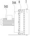
图3是本发明动力端润滑系统结构示意图。Fig. 3 is a schematic structural diagram of the power end lubrication system of the present invention.
图4是本发明动力端润滑系统俯视图。Fig. 4 is a top view of the power end lubrication system of the present invention.
图5是本发明动力端润滑系统侧视图。Fig. 5 is a side view of the power end lubrication system of the present invention.
图6是本发明水帘式冷却器结构组成示意图。Fig. 6 is a schematic diagram of the structure and composition of the water curtain cooler of the present invention.
图7是本发明水帘式冷却器水帘模块结构组成示意图。Fig. 7 is a schematic diagram of the structure and composition of the water curtain module of the water curtain cooler of the present invention.
图8是本发明交流变频钻井泵的结构示意。Fig. 8 is a structural representation of the AC variable frequency drilling pump of the present invention.
图9是本发明交流变频钻井泵正视图的结构示意。Fig. 9 is a structural representation of the front view of the AC variable frequency drilling pump of the present invention.
图10是本发明交流变频钻井泵俯视图的结构示意图。Fig. 10 is a structural schematic diagram of the top view of the AC variable frequency drilling pump of the present invention.
图11是本发明交流变频钻井泵传动总成的结构示意图。Fig. 11 is a structural schematic diagram of the transmission assembly of the AC variable frequency drilling pump of the present invention.
图12是本发明交流变频钻井泵主动轮装配的结构示意图。Fig. 12 is a structural schematic diagram of the drive wheel assembly of the AC variable frequency drilling pump of the present invention.
图13是图12中B处的放大结构示意图。FIG. 13 is a schematic diagram of an enlarged structure at B in FIG. 12 .
图14是本发明永磁变频钻井泵正视图的结构示意图。Fig. 14 is a structural schematic diagram of the front view of the permanent magnet variable frequency drilling pump of the present invention.
图15是本发明永磁变频钻井泵俯视图的结构示意图。Fig. 15 is a structural schematic diagram of a top view of the permanent magnet variable frequency drilling pump of the present invention.
图16是本发明永磁变频钻井泵传动总成的结构示意图。Fig. 16 is a schematic structural view of the transmission assembly of the permanent magnet variable frequency drilling pump of the present invention.
图17是本发明永磁变频钻井泵主动轮装配的结构示意图。Fig. 17 is a structural schematic diagram of the drive wheel assembly of the permanent magnet variable frequency drilling pump of the present invention.
图18是图17中A处的放大结构示意图。FIG. 18 is a schematic diagram of the enlarged structure at A in FIG. 17 .
图19是本发明箱体的结构示意图。Fig. 19 is a schematic structural view of the box body of the present invention.
图20是本发明动力端总成的结构示意图。Fig. 20 is a schematic structural view of the power end assembly of the present invention.
图21是本发明十字头结构的装配示意图。Fig. 21 is a schematic diagram of the assembly of the crosshead structure of the present invention.
图22是本发明液力端总成的结构示意图Figure 22 is a schematic structural view of the liquid end assembly of the present invention
图中标记:1-传动总成、11-电机模块、12-主动轮、13-从动轮、14-曲轴、15-支撑轴承、16-连杆、17-转动轴、18-机架、19-轴承座、110-曲拐、111-曲轴箱、112-电机座、2-动力端总成、21-十字头箱体、22-十字头结构、221-滑道壳体、223-伸缩杆、222-十字铰、23-十字头腔室、24-箱体盖板、25-缸腔室、26-前墙板、3-液力端总成、31-液力端机架、32-活塞缸、33-活塞杆、34-活塞头、35-螺栓、36-缸套螺栓、37-压板、38-压盖锁紧盘、39-缸套螺母、310-定位销轴、311-缸套退盘、312-吸入管口、313-阀总成、314-吸入腔体、315-排出管口、316-排出腔体、317-端部法兰耐、318-限位块、319-耐磨盘、4-底座、5-动力端润滑系统、51-撬座、52-润滑油泵、521-油泵进油口、522-油泵出油口、53-过滤器、531-过滤器进油口、532-过滤器排油口一、533-过滤器排油口二、54-冷却器、541-冷却器进油口、542-冷却器出油口、543-电机、544-散热叶片、55-温控开关、56-吸入管口、57-排油管口、58-溢油管路、6-液力端润滑系统、7-水帘模块、71-壳体、711-冷却水入口、72-散热水帘墙、73-入水分水管、74-出水口、75-积水池、8-热交换模块、9-吊装架机构、10-小滑车。Marks in the figure: 1-transmission assembly, 11-motor module, 12-driving wheel, 13-driven wheel, 14-crankshaft, 15-support bearing, 16-connecting rod, 17-rotating shaft, 18-frame, 19 -Bearing seat, 110-Crank, 111-Crankcase, 112-Motor base, 2-Power end assembly, 21-Crosshead box, 22-Crosshead structure, 221-Slide housing, 223-Telescopic rod , 222-cross hinge, 23-crosshead chamber, 24-box cover, 25-cylinder chamber, 26-front wall, 3-fluid end assembly, 31-fluid end frame, 32- Piston cylinder, 33-piston rod, 34-piston head, 35-bolt, 36-liner bolt, 37-pressure plate, 38-gland locking disc, 39-liner nut, 310-locating pin, 311-cylinder Set back plate, 312-suction nozzle, 313-valve assembly, 314-suction cavity, 315-discharge nozzle, 316-discharge cavity, 317-end flange resistance, 318-limit block, 319- Wear-resistant plate, 4-base, 5-power end lubrication system, 51-skid seat, 52-lubricating oil pump, 521-oil pump inlet, 522-oil pump outlet, 53-filter, 531-filter oil inlet Port, 532-filter oil outlet one, 533-filter oil outlet two, 54-cooler, 541-cooler oil inlet, 542-cooler oil outlet, 543-motor, 544-radiating blade, 55-temperature control switch, 56-suction nozzle, 57-oil discharge nozzle, 58-oil overflow pipeline, 6-fluid end lubrication system, 7-water curtain module, 71-housing, 711-cooling water inlet, 72-radiation water curtain wall, 73-water inlet pipe, 74-water outlet, 75-reservoir pool, 8-heat exchange module, 9-hanging frame mechanism, 10-small block.
具体实施方式Detailed ways
本说明书中公开的所有特征,或公开的所有方法或过程中的步骤,除了互相排斥的特征和/或步骤以外,均可以以任何方式组合。All features disclosed in this specification, or steps in all methods or processes disclosed, may be combined in any manner, except for mutually exclusive features and/or steps.
本说明书中公开的任一特征,除非特别叙述,均可被其他等效或具有类似目的的替代特征加以替换。即,除非特别叙述,每个特征只是一系列等效或类似特征中的一个例子而已。1Any feature disclosed in this specification, unless specifically stated, can be replaced by other alternative features that are equivalent or have similar purposes. That is, unless expressly stated otherwise, each feature is one example only of a series of equivalent or similar features. 1
实施例1Example 1
一种大功率五缸钻井泵组,如图1至图22所示,包括底座4,所述底座上设置有钻井泵和润滑系统,所述钻井泵包括传动总成1、动力端总成2以及液力端总成3,所述润滑系统包括用于传动总成1及动力端总成2润滑和冷却的动力端润滑系统5,用于液力端总成3润滑和冷却的液力端润滑系统6;A high-power five-cylinder drilling pump set, as shown in Figures 1 to 22, includes a
所述动力端润滑系统5包括撬座51,所述撬座上设置有润滑油泵52,以及用于润滑油过滤的并与润滑油泵52连通的过滤器53,所述过滤器53连通钻井泵,以及连通有用于润滑油冷却的冷却器54,所述过滤器53设置有温控开关55,通过所述温控开关55控制润滑油从所述过滤器53出来后进入钻井泵进行润滑冷却或者进入冷却器54中进行冷却。The power
在本实施例中,基于钻井泵的设计基础上,针对整个钻井泵组进行了冷却系统的结构设计,在本设计中,以每个单元作为独立分开的进行设计能够有效的实现整个结构的紧凑,简化结构的效果,作为具体的效果描述,在现场应用中,其结构的更为简单,占地空间更小,得到的优势相对于传统结构更加明显。In this embodiment, based on the design of the drilling pump, the structural design of the cooling system is carried out for the entire drilling pump group. In this design, each unit is designed as an independent and separate design, which can effectively realize the compactness of the entire structure , the effect of simplifying the structure is described as a specific effect. In the field application, the structure is simpler, the floor space is smaller, and the advantages obtained are more obvious than the traditional structure.
基于上述具体结构的设计基础上,作为更加具体的设计,所述动力端润滑系统5采用风冷或水冷。Based on the design of the above specific structure, as a more specific design, the power
作为润滑系统更加具体的设计,在具体的实施方式中,作为更加具体的设计,所述动力端润滑系统5包括吸入管口56和排油管口57,所述润滑油泵52设置有油泵进油口521和油泵出油口522,所述吸入管口56连通油泵进油口521,所述排油管口57连通钻井泵;As a more specific design of the lubrication system, in a specific embodiment, as a more specific design, the power
所述过滤器53设置有过滤器进油口531,所述过滤器进油口531连通油泵出油口522,所述过滤器53还设置有过滤器排油口一532和过滤器排油口二533,所述过滤器排油口一532连通冷却器54以用于润滑油冷却,所述过滤器排油口二533连通排油管口57以用于将润滑油送入到钻井泵当中。The
在此结构的设计中,其主要的设计目的是为了有效的实现润滑油的冷却效果,在具体的应用当中,润滑油在未满足冷却后的温度,其结构是为了使润滑油继续冷却,最主要的功能不仅仅是需要保持其润滑效果,同时还需要供应器具体的冷却效果。In the design of this structure, its main design purpose is to effectively realize the cooling effect of the lubricating oil. In specific applications, the lubricating oil does not meet the temperature after cooling, and its structure is to keep the lubricating oil cooling. The main function is not only to maintain its lubricating effect, but also the specific cooling effect of the supplier.
作为上述具体结构的设计基础上,针对冷却器进行进一步的优化设计,所述冷却器54设置有冷却器进油口541和冷却器出油口542,所述冷却器进油口541连通过滤器排油口一532,所述冷却器出油口542连通排油管口57以实现冷却后的润滑液进入钻井泵。此设计的主要目的是为了将冷却后的润滑油直接应用于钻井泵的润滑和冷却。On the basis of the design of the above-mentioned specific structure, a further optimization design is carried out for the cooler, the cooler 54 is provided with a
作为更加具体的设计,所述动力端润滑系统5还设置有溢油管路58,所述溢油管路58通过溢流安全阀组连通系统油路管路,通过溢流安全阀组检测油压以控制润滑油的溢流。As a more specific design, the power
基于上述具体结构的设计基础上,作为更加具体的描述,动力端润滑系统与各摩擦副之间通过管路系统连接,管路系统内有压力、温度等传感器,通过电控系统智能检测油温、油压等运行参数。Based on the design of the above specific structure, as a more specific description, the power end lubrication system and each friction pair are connected through a pipeline system. There are pressure, temperature and other sensors in the pipeline system, and the oil temperature is intelligently detected through the electronic control system. , oil pressure and other operating parameters.
综上,动力端润滑系统为动力端轴承、齿轮、十字头等摩擦副提供一定压力的润滑油,起润滑、冷却作用,可通过润滑油带走摩擦副产生的热量。To sum up, the power end lubrication system provides lubricating oil at a certain pressure for friction pairs such as power end bearings, gears, and crossheads, which plays a role in lubrication and cooling, and can take away the heat generated by the friction pairs through the lubricating oil.
作为更加具体的设计,所述液力端润滑新系统6采用水冷进行冷却和润滑。As a more specific design, the new liquid end lubrication system 6 adopts water cooling for cooling and lubrication.
基于上述具体的结构设计基础上,作为更加具体的设计,所述底座4上还设置有吊装架机构9,所述吊装机架上还设置有小滑车10,所述小滑车可在吊装机架上滑动。在下述实施例当中会涉及到液力端总成3中设计的活塞缸32,将其装配至缸腔室25中时需要改结构实现吊装。Based on the above-mentioned specific structural design basis, as a more specific design, the
实施例2Example 2
在实施例1的设计基础上,作为具体的描述,如图6和图7所示,在上述具体的结构设计基础上,作为更加具体的设计,所述冷却器54包括动力模块、热交换模块8和水帘模块7,所述动力模块采用空气吸入的方式实现冷却,所述动力模块包括电机543以及设置于电机转子上的散热扇叶544。On the basis of the design of
在本实施例中,其热交换模块8采用成熟的设计,内有带散热翅片的冷却盘管,增大散热面积。而动力模块主要是提供抽风的动力,实现空气能够通过水帘模块后经过热交换模块8,从而实现润滑油的冷却。In this embodiment, the
作为更加具体的设计,在上述具体结构的设计基础上,针对水帘模块进一步设计,水帘模块7包括壳体71、散热水帘墙72、入水分水管73、出水口74和积水池75,所述壳体71设置有冷却水入口711,并通过入水分水管73接通水源,还包括分水装置,通过分水装置将水均匀的进入散热水帘墙上部。As a more specific design, on the basis of the design of the above-mentioned specific structure, the water curtain module is further designed. The
本实施例中,其工作原理为:电机543启动后,空气从散热水帘墙72进入,然后通过换热模块8的换热管,带走热量。当散热水帘墙72接通水源后,水帘墙各表面都被浸湿,并在外表面形成水膜。外界的热空气通过水帘时,可以使得水帘墙表面的水分快速蒸发吸热,对入口空气进行冷却。使得进入换热模块8的空气温度大大降低,与待冷却液体温差加大,从而提高冷却器的换热效率和冷却效果。散热水帘墙72保持湿润即可,蒸发和供水保持平衡,因此需要的水流量很小,当环境温度较高(大于35℃)时,水帘模块7通过水分的快速蒸发,可以使进入冷却器5的空气温度降低大约8-10℃,可以有效提高高温环境时冷却器的换热效率,保证高温环境时动力端润滑系统有效控制系统润滑油温度,从而保证润滑系统可靠性工作,同时水帘模块只在环境温度较高(大于35℃)润滑油温度不能有效控制在较低范围内时使用,并不需要长期提供水源工作,不会使用大量水资源,可以经济有效的解决润滑系统在较高温度时的工作可靠性。In this embodiment, its working principle is: after the
实施例3Example 3
在实施例1和实施例2的设计基础上,体现出钻井泵的设计结构,作为具体的设计,如图8至图22所示,所述传动总成1包括电机模块11、传动机构以及曲柄连杆机构,所述电机模块11通过传动机构连接装配曲柄连杆机构,通过电机模块11以实现曲柄连杆机构的运动;On the basis of the design of
所述动力端总成2包括多个动力单元,每个所述动力单元装配连接于曲柄连杆机构,另一端部分别独立装配一个所述液力端总成3的活塞机构,通过所述动力端总成2以实现对所述液力端总成3的驱动。The
在本实施例中,本设计将钻井泵作为模块式设计,针对传动总成1、动力端总成2以及液力端总成3采用模块化的设计,有效的可实现简化整个结构,使得整个结构具备更好的空间简化的效果。同时,在整个设备的维护上,此结构设计更具有便于维护的优势,在工作效率上也更加具备更好的效果。In this embodiment, this design uses the drilling pump as a modular design, and adopts a modular design for the
基于上述具体结构的设计基础上,作为进一步的设计,针对传动总成进行具体的优化以及设计,在另一具体实施方式中,所述传动总成1包括机架18,所述机架18上设置有电机模块11,所述传动机构包括设置于电机模块11上的主动轮12,以及用于驱动曲柄连杆机构的从动轮13,所述曲柄机构包括曲轴14,所述曲轴设置有从动轮13,所述曲轴14上装配有多个支撑轴承15和多根连杆16。在本设计中,通过电机模块通过传动机构驱动曲柄连杆机构作为整个设备的动力输出部分。Based on the design of the above-mentioned specific structure, as a further design, specific optimization and design are carried out for the transmission assembly. In another specific embodiment, the
作为更加具体的设计,在上述具体结构的设计基础上,作为更加具体的设计,所述电机模块11的两侧设置有主动轮12,所述曲轴的两端部设置有从动轮13,所述电机模块11控制2个主动轮12同步转动,所述主动轮12与从动轮13配合以实现曲轴14的转动。在此设计中,通过主动轮12直接驱动从动轮的结构设计能够有效的解决带传动、链传动所带来的结构复杂的问题。作为更加具体的描述,通过该结构的设计有效的实现了整个传动总成实现模块化的设计,并且可以实现整个部分集成化,不仅便于安装也便于运输,减少零部件。As a more specific design, on the basis of the design of the above specific structure, as a more specific design, the two sides of the
在上述具体结构的设计基础上,作为具体的描述,针对机架18进行具体的设计,所述机架18包括曲轴箱111,所述曲轴箱111装配设置有电机座112,电机座112的两侧设置有用于装配电机转轴的轴承座19。在本结构设计中,电机座112用于电机模块的设计,同时,在装配位上,还设置有用于防倾斜的连接块,电机装配好后并与连接块固定装配。而曲轴箱111的结构是应用于装配曲轴连接结构。On the basis of the design of the above-mentioned specific structure, as a specific description, a specific design is carried out for the
在上述具体结构的设计基础上,作为更加具体的设计,所述电机模块11两侧设置有转动轴17,所述转动轴17的两端固定装配有主动轮12。On the basis of the design of the above specific structure, as a more specific design, a rotating
针对主动轮12装配于转动轴17上,作为具体的描述,在本实施例中,所述主动轮12固定装配于所述转动轴17上,以实现所述主动轮12与所述转动轴17同步转动,采用更为较优的设计,所述主动轮12通过过盈配合的方式装配于转动轴17上。For the assembly of the
而在过盈配合中,其具体实施方式具有不同的方式,作为更加优选的结构的,所述主动轮12具有锥形内孔,转动轴17的端部为锥形柱,并通过过盈配合实现锥形内孔和锥形柱的装配,以便于主动轮12的拆卸。该结构的设计更具备维护的便捷,在拆卸时一旦具有松动则可有效的实现主动轮12的拆卸。In the interference fit, its specific implementation method has different modes. As a more preferred structure, the
在上述具体结构的设计基础上,以及作为转动轴的具体设计,作为具体的,所述转动轴17为整体式结构,或者,转动轴为分体式结构,且在电机模块的作用下实现同步转动。在本结构的设计中,以作为更加优选的方式,所述转动轴17为整体式结构。即:主动轮12是同轴设置的。特别说明,为了保证曲轴14的转动,即使在为分体式结构设计,即主动轮12分别连接一根转动轴,但是具体的要求是:2个主动轮12的转动为同步转动。On the basis of the design of the above-mentioned specific structure, as well as the specific design of the rotating shaft, specifically, the rotating
在上述具体结构的设计基础上,针对曲柄连杆机构进行深入的设计,作为更加具体的,所述曲轴14上具有多个曲拐110,所述曲轴14通过多个支撑轴承15固定装配于机架18上,所述曲拐110位于相邻两个支撑轴承15之间,并在曲拐上装配连接连杆16。在发动机的领域中,通过曲拐110处装配大小头连杆以实现驱动的效果,而其连杆16的大头装配在曲拐上,另一端部则是连接被驱动部件上。On the basis of the design of the above-mentioned specific structure, an in-depth design is carried out for the crank linkage mechanism. More specifically, the
作为更加具体的设计,所述支撑轴承15具有6个,所述曲拐110具有5个。在本设计中,所设计的结构为5缸式结构。传统结构多为3缸式,而其所具备的差异还是基于整个结构,在本结构更具有简单,结构更模块化,而传统结构相对设备较大,结构复杂,而在缸体的设计也就产生了实质性差异。As a more specific design, there are six
针对曲轴箱111以及具体的曲柄连杆结构进行具体的设计,曲轴14由合金钢锻造而成。所述曲轴14由六个轴颈和五个曲拐110组成,6个支撑轴承安装固定在六个支撑轴承座上。6个支撑轴承座采用整体式曲轴轴承座,其中一侧(优选最左侧)一个轴承座采用定位止口设计,曲轴14先热装轴承内圈和保持架后,整体从选择的一侧吊入支撑轴承座,安装精度高,可靠性强。五缸钻井泵的曲轴支撑结构采用6点支撑梁结构,相比常规钻井泵的两点支撑简支梁结构,主轴承受力更小,使用寿命更长,有效减少客户的维护成本。Specifically designed for the
在上述具体结构的设计基础上,针对主动轮12以及从动轮13进行具体的装配设计,其结构具体方式具有如下方式:On the basis of the design of the above-mentioned specific structure, a specific assembly design is carried out for the
1、所述主动轮12与从动轮13之间采用斜齿啮合的方式实现传动;1. The
2、所述主动轮12与从动轮13之间采用直齿啮合的方式实现传动。2. The
作为具体的描述,在啮合方式的设计上,作为更加优选的为第一种方式,即采用斜齿啮合的方式。该结构的设计更具备稳定性,尤其是传动效果上,其使用寿命也具有较好的改善。As a specific description, in terms of the design of the meshing method, the first method is more preferred, that is, the method of helical tooth meshing is adopted. The design of this structure is more stable, especially in terms of transmission effect, and its service life is also better improved.
作为更加具体的设计,在齿轮啮合的基础上,作为其具体作用效果,所述主动轮12的直径小于从动轮13的直径以实现减速效果。As a more specific design, on the basis of gear meshing, as its specific effect, the diameter of the
在上述具体结构的设计基础上,作为更加具体的描述,所述电机模块11为顶置式。结构上采用单电机顶置直驱的结构,电机在机架上方,主动轮12通过锥面直接热装在电机轴两侧,使钻井泵的结构简单,减少宽度方向的尺寸,满足运输要求。Based on the design of the above specific structure, as a more specific description, the
在本实施例中,作为更加具体的设计,如图7至图11所示,所述电机模块11为永磁一体电机。In this embodiment, as a more specific design, as shown in FIGS. 7 to 11 , the
将电机与变频器一体化集成设计,取消了VFD房的设置,永磁电机直接驱动,具有高效节能、制造成本及运输成本低的特点。功率因数从0.83左右提高到0.95及以上;额定效率由0.91左右提高到0.968左右。永磁电机电流更小,铜耗更小,同等功率下额定电流减小350A左右。其结构灵活,体积小,可靠性高。永磁机依靠永磁铁,转子不发热,只需对定子进行水冷。与变频异步电动机相比,节能10%以上,大大降低客户的运营成本。The integrated design of the motor and the frequency converter cancels the setting of the VFD room, and the permanent magnet motor is directly driven, which has the characteristics of high efficiency, energy saving, low manufacturing cost and transportation cost. The power factor is increased from about 0.83 to 0.95 and above; the rated efficiency is increased from about 0.91 to about 0.968. The current of the permanent magnet motor is smaller, the copper consumption is smaller, and the rated current is reduced by about 350A under the same power. It has flexible structure, small size and high reliability. The permanent magnet machine relies on permanent magnets, the rotor does not heat up, and only the stator needs to be water-cooled. Compared with the variable frequency asynchronous motor, it can save energy by more than 10%, which greatly reduces the operating cost of customers.
实施例4Example 4
在实施例1的设计基础上,在电机的设计上,与实施例1不同的是,如图1至图6所示,所述电机模块11为交流变频电机。作为更加优选的,所述电机模块为三相鼠笼式异步电动机。On the basis of the design of
在本实施例中,交流变频电机直接驱动,相对于传统结构传动效率提高3%-5%左右;交流变频电机的性能参数匹配以满足钻井泵的使用要求为目的,按机电融合设计进行制造,使电机具有长寿命、高可靠性和高稳定性,现场维护方便快捷。电机充分利用恒功段,实现超大排量输出。直驱钻井泵最大排量是同级别钻井泵排量的1.2-1.5倍In this embodiment, the AC variable frequency motor is directly driven, and the transmission efficiency is increased by about 3%-5% compared with the traditional structure; the performance parameters of the AC variable frequency motor are matched to meet the requirements of the drilling pump, and it is manufactured according to the electromechanical fusion design. The motor has long life, high reliability and high stability, and the on-site maintenance is convenient and quick. The motor makes full use of the constant power section to achieve super large displacement output. The maximum displacement of the direct drive drilling pump is 1.2-1.5 times that of the same level drilling pump
实施例5Example 5
在实施例1的设计基础上,作为主动轮12与转动轴17之间的装配不同,本实施例不采用过盈配合的方式,具体的,所述主动轮12通过键连接固定装配于转动轴17上。On the basis of the design of
作为具体的描述,在本实施例中其结构也能够实现拆卸的效果的,但是在转子转动的过程中,其作为受到扭矩力的部件为键,虽然效果能够达到,但是其使用寿命是不能够有效的实现锥形面过盈配合的效果。As a specific description, in this embodiment, its structure can also achieve the effect of disassembly, but during the rotation of the rotor, it is a key as a component subjected to torque force. Although the effect can be achieved, its service life cannot be achieved. Effectively realize the effect of interference fit of the tapered surface.
实施例6Example 6
在实施例1的设计基础上,主动轮12和转动轴17之间同样采用过盈配合的设计方式,不同的是,具体的,所述主动轮12具有柱形内孔,转动轴17的端部为圆形柱,并通过过盈配合实现柱形内孔和圆形柱的装配。On the basis of the design of
在本实施例中,采用的常规轴孔与轴的过盈配合效果,其在具体的效果中能够有效的实现作用力较为均衡的功能,但是在拆卸过程中会造成转动轴或者主动轮的损坏,同时也延长了拆卸的时间,不利于维护的效率。In this embodiment, the interference fit effect of the conventional shaft hole and the shaft is used, which can effectively realize the function of relatively balanced force in the specific effect, but it will cause damage to the rotating shaft or the driving wheel during the disassembly process , At the same time, it also prolongs the disassembly time, which is not conducive to the efficiency of maintenance.
实施例7Example 7
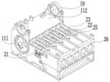
在上述实施例的基础上,针对动力端总成进行更加具体的设计,如图12至图14所示,所述动力端总成2包括十字头箱体21,所述十字头箱体21设置有多个用于装配十字头结构22的十字头腔室23,所述曲柄连杆机构上设置有多个连杆16,每个连杆16与对应的十字头结构22连接装配,在连杆16的作用力下,所述十字头结构22可实现直线往复式运动。On the basis of the above embodiments, a more specific design is carried out for the power end assembly, as shown in Figures 12 to 14, the
在本实施例中,作为具体的描述,为了更好的实现整个结构的设计,十字头结构22在与连杆16装配连接后,由于连杆16是往复式运动,采用十字头结构22后可实现其运动为直线往复式运动,从而有效的实现了驱动的效果。In this embodiment, as a specific description, in order to better realize the design of the entire structure, after the
基于上述具体结构的设计基础上,作为更加具体的设计,所述十字头箱体21还设置有箱体盖板24以用于覆盖十字头腔室23。Based on the design of the above specific structure, as a more specific design, the
在上述具体结构的设计基础上,基于其使用环境所考虑,在具体的结构当中,所述十字头箱体21还设置有箱体盖板24以用于覆盖十字头腔室23。Based on the design of the above-mentioned specific structure and consideration of its use environment, in the specific structure, the
在本实施例中,作为常规的应用,以箱体盖板24作为具体的描述,所述箱体盖板24为一体结构。In this embodiment, as a conventional application, the
在连接结构的设计基础上,作为更加具体的描述以及细节的描述,所述十字头箱体21的前端设置有用于装配曲柄连杆机构的曲轴箱111,所述曲轴箱111上方设置有电机座112,电机座112的两侧设置有用于装配电机转轴的轴承座19,所述十字头箱体21用于装配液力端总成3的端部设置有缸腔室25,所述缸腔室25的端部设置有前墙板26以用于连接液力端总成3。作为具体的,在整个结构的设计中,其结构是将整个动力端总成2形成了个整体式模块,在模块与模块之间的固定装配后,其有效实现了整个结构的紧凑化,并使钻井泵得以更好的减小体积。On the basis of the design of the connection structure, as a more specific description and detailed description, the front end of the
实施例8Example 8
在实施例5的设计基础上,作为更加具体的设计,与实施例5的设计不同的是箱体盖板的结构设计,作为具体的描述,所述箱体盖板24为分体式结构,所述箱体盖板包括多个盖板单元,每个所述十字头腔室上均设置有一个盖板单元,以此提高设备维护的效率。On the basis of the design of
在本实施例中,常规钻井泵是整体式盖板结构,拆卸十字头结构22只能从侧面开口进行拆卸,如果拆卸中间缸的十字头结构22,必须拆卸掉两侧缸的十字头结构22。在装配车间进行对比试验发现,同样拆卸和安装一个中间缸十字头结构22,常规钻井泵3个师傅需要10小时,而本设计中,五缸钻井泵2个师傅需要3小时。这种独立上开口式的十字头箱体大大缩短了客户的维护保养时间。作为更加具体的结构设计,所述十字头结构22包括形成滑道的滑道壳体221,所述滑道壳体221内部设置有伸缩杆223,所述伸缩杆223用于连接连杆16的端部与连杆16通过十字铰222进行铰接,以实现运动方向的改变。In this embodiment, the conventional drilling pump has an integral cover plate structure, and the
实施例9Example 9
在上述实施例的设计基础上,针对液力端总成的设计进行具体的设计,如图15所示,所述液力端总成3包括液体吸入模块、液体排出模块以及连接动力端总成的活塞机构,通过活塞机构的运动以控制液体的吸入和排出;On the basis of the design of the above embodiments, a specific design is made for the design of the fluid end assembly, as shown in Figure 15, the
在活塞机构收缩的状态下,液体吸入模块吸入液体;In the state where the piston mechanism is contracted, the liquid suction module sucks liquid;
在活塞机构推进的状态下,液体排出模块排出液体。In a state where the piston mechanism is advanced, the liquid discharge module discharges liquid.
在结构的设计中,作为液力端总成的设计上,通过活塞机构的往复式运动,在基于吸入模块和排出模块的设计,能够有效的实现液体的进入和排出,作为特别的说明,该结构能够有效的完成整个结构的钻井液的循环。同时整个结构也需要进行模块化的结构设计。In the design of the structure, as the design of the liquid end assembly, through the reciprocating movement of the piston mechanism, the design based on the suction module and the discharge module can effectively realize the entry and discharge of liquid. As a special illustration, the The structure can effectively complete the circulation of drilling fluid throughout the structure. At the same time, the entire structure also needs to be modularized.
具体的,在上述具体结构的设计基础上,在其中一具体实施方式中,所述液力端总成3包括液力端机架31,所述活塞机构包括装配于液力端机架上的活塞缸32,以及位于活塞缸32内部的活塞杆33和设置于活塞杆端部的活塞头34,所述活塞杆33的另一端与动力端总成2装配以实现活塞机构的运行。在本结构的设计中,其结构不经需要考虑到与前端装置的装配,也需要考虑到本身结构的装配,尤其是在将结构实现模块化设计,当然,其主要目的也是为了更好的实现结构简单化以及紧凑化。作为更加具体的设计,所述活塞杆33通过卡箍连接十字头结构。Specifically, on the basis of the design of the above-mentioned specific structure, in one specific embodiment, the
作为更加具体的设计,基于上述具体实施方式的设计基础上,所述动力端总成2用于装配液力端总成的端部设置有缸腔室25,所述缸腔室25的端部设置有前墙板26以用于连接液力端总成3。As a more specific design, based on the design of the above specific embodiment, the end of the
作为更加具体的结构设计,所述活塞机构可装配于缸腔室25内以便于活塞机构与动力端总成2的装配。As a more specific structural design, the piston mechanism can be assembled in the
基于上述具体结构的设计基础上,所述液力端机架31通过螺栓35与所述前墙板装配以实现整体装置的装配。在该结构的设计中,所述螺栓35为双头螺栓。两端通过螺母进行把合拉紧。Based on the design of the above specific structure, the
在结构的设计上,为了实现活塞缸装配在液力端机架的端部,作为具体的描述,所述活塞缸32通过多个缸套螺栓36装配于液力端机架31上,所述活塞缸32上还设置有压板37,缸套螺栓36通过穿过压板37并把合在液力端机架31上。在动作过程中,在活塞缸32的端部设置有端部法兰317,所述缸套螺栓36为双头螺栓,所述活塞缸32上设置有限位块318,所述压板37装配于限位块318处并与限位块318贴合装配,所述缸套螺栓36穿过压板37、限位块318后通过螺纹穿过端部法兰317装配在液力端机架31上。在压板37的前端部通过缸套螺母39进行把合。In terms of structural design, in order to realize that the piston cylinder is assembled on the end of the liquid end frame, as a specific description, the
基于上述具体结构的设计基础上,为了保证装配效果,具体的,所述压板37的前端设置有压盖锁紧盘38,所述压盖锁紧盘38通过缸套螺母39实现定位,在所述压盖锁紧盘38的后端设置有缸套螺母39用于与压板37贴合以实现定位,在压盖锁紧盘38的前端设置有缸套螺母39以实现压盖锁紧盘38位于两个缸套螺母39之间。通过该方式能够进一步的保证整个装置的装配效果。Based on the design of the above-mentioned specific structure, in order to ensure the assembly effect, specifically, the front end of the
作为更加具体的设计,为了便于拆装,所述压板37的后端设置有缸套退盘机构,所述缸套退盘机构包括固定在活塞缸32外侧的定位销轴310,以及缸套退盘311,所述缸套退盘311可沿缸套螺栓36轴向移动,在所述缸套退盘311的端部还设置有缸套螺母39,所述活塞缸32上设置有限位块318,所述缸套螺母39的前端与限位块318贴合装配,所述缸套退盘311与定位销轴310固定连接装配;As a more specific design, in order to facilitate disassembly, the rear end of the
在拆卸缸套时,使压板37前端的缸套螺母39退出一定的距离或者拆卸下来后,通过拧缸套退盘311后端的缸套螺母39以实现活塞缸32的退出。When dismounting the cylinder liner, make the
在该结构中,先拆卸位于前端的缸套螺母,压板37前端的缸套螺母39退出后,在拧动所述缸套退盘311后端的缸套螺母39可推动缸套退盘带动定位销轴310并带动活塞缸向外退,从而实现快速拆卸的效果。In this structure, the cylinder liner nut at the front end is disassembled first, and after the
作为更加具体的设计,在所述活塞缸32与液力端机架31装配端面之间还设置有耐磨盘319,以提高整个装置的使用寿命。As a more specific design, a wear-
在上述具体的结构设计上,针对液力端总成3的吸入模块和排出模块进行设计,具体的:In the specific structural design above, the suction module and discharge module of the
所述液体吸入模块包括吸入管口312、阀总成313以及吸入腔体314,在活塞机构的作用下,控制阀总成的开启/闭合控制吸入管口的液体进入。The liquid suction module includes a
所述液体排出模块包括排出管口315、阀总成313以及排出腔体316,所述吸入腔体316连通排出腔体314,在活塞机构的作用下,控制排出模块的阀总成313的开启/闭合控制排出管口的液体排出。The liquid discharge module includes a
在上述具体的结构设计中,作为动作的具体描述,在阀总成313的设计上,可以看到,在阀杆的设计处是具有弹性件的,为更好的说明情况,在活塞退出时,吸入模块的阀总成在吸力的作用下向上开启,并通入液体,此时,排出模块的阀总成收到向下的力,保持关闭的状态;而在活塞向前运动时,由于内部的压力,使吸入模块的阀总成收到向下的推力,吸入模块保持关闭状态,而此时排出模块的阀总成受到向上的推力,促使排出模块的阀总成开启,从而实现液体的排出。In the specific structural design above, as a specific description of the action, in the design of the
结合上述实施例的基础上,为了便于整个钻井泵的吊装,具体的结构上,还包括用于吊装的吊耳。具体的,直驱钻井泵体积小、重量轻,适合安装在陆地泵房、海洋钻井平台、运输拖挂车,并且可用于直升机吊装。Based on the above embodiments, in order to facilitate the hoisting of the entire drilling pump, the specific structure also includes lifting lugs for hoisting. Specifically, the direct-drive drilling pump is small in size and light in weight, and is suitable for installation in land pump rooms, offshore drilling platforms, transport trailers, and can be used for hoisting by helicopters.
实施例10Example 10
一种固控系统,包括实施例1至实施例9任意单一或者组合实施例所述的一种大功率五缸钻井泵组。A solids control system, including a high-power five-cylinder drilling pump set described in any single or combined embodiment of
实施例11Example 11
一种钻机,包括实施例1至实施例9任意单一或者组合实施例所述的一种大功率五缸钻井泵组。A drilling rig, including a high-power five-cylinder drilling pump set described in any single or combined embodiment of
综上所述:In summary:
1、本发明的一种大功率五缸钻井泵组在整个结构的设计上实现了模块化设计,在结构的空间布局上能够有效的解决传统钻井泵或者钻井泵组结构较大的问题,借助传统的结构设计基础上,以本申请解决了带传动、链传动等中间机械变速传动机构所带来的结构复杂的问题,有效的实现了整个结构的优化效果。1. A high-power five-cylinder drilling pump set of the present invention realizes a modular design in the design of the entire structure, and can effectively solve the problem of a larger structure of the traditional drilling pump or the drilling pump set in terms of the spatial layout of the structure. On the basis of traditional structural design, this application solves the problem of complex structure caused by intermediate mechanical transmission mechanisms such as belt transmission and chain transmission, and effectively realizes the optimization effect of the entire structure.
2、基于电机的设计,在结构上采用单电机顶置直驱的结构,电机在机架上方,小齿轮通过锥面直接热装在电机轴两侧,使钻井泵的结构简单,减少宽度方向的尺寸,满足运输要求。2. Based on the design of the motor, the structure adopts a single-motor top-mounted direct-drive structure. The motor is above the frame, and the pinion is directly heat-packed on both sides of the motor shaft through the tapered surface, so that the structure of the drilling pump is simple and the width direction is reduced. The size meets the transportation requirements.
3、本发明所采用的五缸设计,排出流量和压力波动相比三缸钻井泵减少16.5%,高压下压力波动仅有2%-3%。3. With the five-cylinder design adopted in the present invention, the discharge flow rate and pressure fluctuation are reduced by 16.5% compared with the three-cylinder drilling pump, and the pressure fluctuation under high pressure is only 2%-3%.
4、在冷却系统的设计上,润滑冷却系统采用特殊设计的水帘式风冷却器,当环境温度较高(大于35℃)时,水帘模块通过水分的快速蒸发,可以使进入冷却器的空气温度降低大约8-10℃,可以有效提高高温环境时冷却器的换热效率,保证高温环境时动力端润滑系统有效控制系统润滑油温度,从而保证润滑系统可靠性工作。4. In the design of the cooling system, the lubricating cooling system adopts a specially designed water curtain air cooler. When the ambient temperature is high (greater than 35°C), the water curtain module can quickly evaporate water to make the water entering the cooler The air temperature is lowered by about 8-10°C, which can effectively improve the heat transfer efficiency of the cooler in high-temperature environments, and ensure that the power-end lubrication system can effectively control the lubricating oil temperature in high-temperature environments, thereby ensuring the reliability of the lubrication system.
本发明并不局限于前述的具体实施方式。本发明扩展到任何在本说明书中披露的新特征或任何新的组合,以及披露的任一新的方法或过程的步骤或任何新的组合。The present invention is not limited to the foregoing specific embodiments. The present invention extends to any new feature or any new combination disclosed in this specification, and any new method or process step or any new combination disclosed.
Claims (21)
Priority Applications (4)
| Application Number | Priority Date | Filing Date | Title |
|---|---|---|---|
| CN202110726364.8ACN113790135B (en) | 2021-06-29 | 2021-06-29 | High-power five-cylinder drilling pump set, solid control system and drilling machine |
| PCT/CN2022/073706WO2023273330A1 (en) | 2021-06-29 | 2022-01-25 | High-power five-cylinder drilling pump set, solid control system, and drilling rig |
| US18/278,810US20240125320A1 (en) | 2021-06-29 | 2022-01-25 | High-power five-cylinder drilling pump set, solid control system and drilling rig |
| SA523442375ASA523442375B1 (en) | 2021-06-29 | 2023-01-30 | High-power five-cylinder drilling pump set, solid control system, and drilling rig |
Applications Claiming Priority (1)
| Application Number | Priority Date | Filing Date | Title |
|---|---|---|---|
| CN202110726364.8ACN113790135B (en) | 2021-06-29 | 2021-06-29 | High-power five-cylinder drilling pump set, solid control system and drilling machine |
Publications (2)
| Publication Number | Publication Date |
|---|---|
| CN113790135A CN113790135A (en) | 2021-12-14 |
| CN113790135Btrue CN113790135B (en) | 2023-06-09 |
Family
ID=78876988
Family Applications (1)
| Application Number | Title | Priority Date | Filing Date |
|---|---|---|---|
| CN202110726364.8AActiveCN113790135B (en) | 2021-06-29 | 2021-06-29 | High-power five-cylinder drilling pump set, solid control system and drilling machine |
Country Status (4)
| Country | Link |
|---|---|
| US (1) | US20240125320A1 (en) |
| CN (1) | CN113790135B (en) |
| SA (1) | SA523442375B1 (en) |
| WO (1) | WO2023273330A1 (en) |
Families Citing this family (3)
| Publication number | Priority date | Publication date | Assignee | Title |
|---|---|---|---|---|
| CN113790135B (en)* | 2021-06-29 | 2023-06-09 | 四川宏华石油设备有限公司 | High-power five-cylinder drilling pump set, solid control system and drilling machine |
| CN114776551A (en)* | 2022-03-29 | 2022-07-22 | 兰州兰石石油装备工程股份有限公司 | Multi-cylinder large-flow high-pressure mud pump |
| CN119844363B (en)* | 2024-12-20 | 2025-09-30 | 启东市永跃金属铸造有限公司 | Automatic oil discharging device of steering oil pump |
Family Cites Families (15)
| Publication number | Priority date | Publication date | Assignee | Title |
|---|---|---|---|---|
| DE10124031B4 (en)* | 2001-05-16 | 2009-08-20 | Daimler Ag | Reciprocating engine with a driver |
| US7811064B2 (en)* | 2005-08-18 | 2010-10-12 | Serva Corporation | Variable displacement reciprocating pump |
| CN102536792B (en)* | 2012-03-30 | 2015-06-10 | 四川宏华石油设备有限公司 | Lubricating device for drill pump |
| CN103541880B (en)* | 2013-10-23 | 2016-02-10 | 四川宏华石油设备有限公司 | The drilling well helical gear installation method of five cylinder pumps and five cylinder pumps thereof |
| CN104196715A (en)* | 2014-08-21 | 2014-12-10 | 天津市通洁高压泵制造有限公司 | Power end lubricating oil circulation cooling system with overflow function |
| US11209124B2 (en)* | 2016-06-23 | 2021-12-28 | Spm Oil & Gas Inc. | Power frame and lubrication system for a reciprocating pump assembly |
| CN106089617B (en)* | 2016-08-02 | 2018-09-28 | 山东科瑞泵业有限公司 | A kind of drilling mud shaking pump |
| CN106351826A (en)* | 2016-10-26 | 2017-01-25 | 四川宏华石油设备有限公司 | Novel drilling pump cooler |
| CN106368942B (en)* | 2016-11-08 | 2018-04-17 | 四川宏华石油设备有限公司 | A kind of reciprocal pump liner pressing device |
| CN208605915U (en)* | 2018-06-19 | 2019-03-15 | 常州市新创智能科技有限公司 | A kind of oil circuit cooling device |
| CN110617187A (en)* | 2019-10-29 | 2019-12-27 | 烟台杰瑞石油装备技术有限公司 | High-power five-cylinder plunger pump |
| CN211144459U (en)* | 2019-11-20 | 2020-07-31 | 华中科技大学鄂州工业技术研究院 | Multifunctional fracturing equipment |
| CN113464392B (en)* | 2021-06-29 | 2023-06-16 | 四川宏华石油设备有限公司 | High-power five-cylinder drilling pump, drilling pump set, solid control system and drilling machine |
| CN113464391B (en)* | 2021-06-29 | 2023-06-13 | 四川宏华石油设备有限公司 | A high-power five-cylinder drilling pump system, solids control system and drilling rig |
| CN113790135B (en)* | 2021-06-29 | 2023-06-09 | 四川宏华石油设备有限公司 | High-power five-cylinder drilling pump set, solid control system and drilling machine |
- 2021
- 2021-06-29CNCN202110726364.8Apatent/CN113790135B/enactiveActive
- 2022
- 2022-01-25USUS18/278,810patent/US20240125320A1/enactivePending
- 2022-01-25WOPCT/CN2022/073706patent/WO2023273330A1/ennot_activeCeased
- 2023
- 2023-01-30SASA523442375Apatent/SA523442375B1/enunknown
Also Published As
| Publication number | Publication date |
|---|---|
| US20240125320A1 (en) | 2024-04-18 |
| SA523442375B1 (en) | 2024-05-14 |
| CN113790135A (en) | 2021-12-14 |
| WO2023273330A1 (en) | 2023-01-05 |
Similar Documents
| Publication | Publication Date | Title |
|---|---|---|
| CN113790135B (en) | High-power five-cylinder drilling pump set, solid control system and drilling machine | |
| CN113464391B (en) | A high-power five-cylinder drilling pump system, solids control system and drilling rig | |
| CN110617318B (en) | A five-cylinder plunger pump with an integral power end structure | |
| US20200332788A1 (en) | Super-power five-cylinder plunger pump | |
| US20210087943A1 (en) | Five cylinder plunger pump | |
| CN110617188B (en) | Multi-point supported five-cylinder plunger pump | |
| US20210123425A1 (en) | High power quintuplex plunger pump | |
| CN113464392B (en) | High-power five-cylinder drilling pump, drilling pump set, solid control system and drilling machine | |
| CN210769169U (en) | High-power five-cylinder plunger pump | |
| US20200332784A1 (en) | Double-motor double-pump electric drive fracturing semi-trailer | |
| WO2020211086A1 (en) | Dual-motor dual-pump electric drive fracturing semi-trailer | |
| WO2020211083A1 (en) | Super-power five-cylinder piston pump | |
| RU2511985C2 (en) | Vertical wind power generator | |
| CN2898367Y (en) | Five-plunger three-support forced lubrication emulsion pump | |
| CN101943170A (en) | Sea water circulating pump for nuclear power station | |
| CN115773354A (en) | Special parallel gear box of full-electric large-torque injection molding machine | |
| CN111156159B (en) | A full-load parallel reciprocating piston compressor stepless air volume regulating mechanism | |
| WO2020253471A1 (en) | Reciprocating sealing-ring-free piston hydraulic braking device | |
| CN210218020U (en) | Direct-connected oil medium-pressure compressor using gasoline engine as power source | |
| CN109519383B (en) | Vertical oil cooling integrated screw compressor and oil cooling method thereof | |
| CN113898681A (en) | Shafting lubricating structure of parallel hydraulic retarder | |
| CN220979674U (en) | Integrated bearing platform for V-shaped six-cylinder diesel engine | |
| CN206770323U (en) | A kind of close-coupled pump hydraulic pumping plant | |
| WO2021081752A1 (en) | Five-cylinder plunger pump having integrated-type power end structure | |
| CN109915340A (en) | Long wheelbase three-row three-cylinder vertical compressor |
Legal Events
| Date | Code | Title | Description |
|---|---|---|---|
| PB01 | Publication | ||
| PB01 | Publication | ||
| SE01 | Entry into force of request for substantive examination | ||
| SE01 | Entry into force of request for substantive examination | ||
| GR01 | Patent grant | ||
| GR01 | Patent grant |