CN113777785B - Diffraction optical waveguide AR system, AR glasses and configuration method of the system - Google Patents
Diffraction optical waveguide AR system, AR glasses and configuration method of the systemDownload PDFInfo
- Publication number
- CN113777785B CN113777785BCN202111019613.6ACN202111019613ACN113777785BCN 113777785 BCN113777785 BCN 113777785BCN 202111019613 ACN202111019613 ACN 202111019613ACN 113777785 BCN113777785 BCN 113777785B
- Authority
- CN
- China
- Prior art keywords
- grating
- coupling
- light
- height
- width
- Prior art date
- Legal status (The legal status is an assumption and is not a legal conclusion. Google has not performed a legal analysis and makes no representation as to the accuracy of the status listed.)
- Active
Links
Images


Classifications
- G—PHYSICS
- G02—OPTICS
- G02B—OPTICAL ELEMENTS, SYSTEMS OR APPARATUS
- G02B27/00—Optical systems or apparatus not provided for by any of the groups G02B1/00 - G02B26/00, G02B30/00
- G02B27/01—Head-up displays
- G02B27/017—Head mounted
- G02B27/0172—Head mounted characterised by optical features
- G—PHYSICS
- G02—OPTICS
- G02B—OPTICAL ELEMENTS, SYSTEMS OR APPARATUS
- G02B27/00—Optical systems or apparatus not provided for by any of the groups G02B1/00 - G02B26/00, G02B30/00
- G02B27/01—Head-up displays
- G02B27/0101—Head-up displays characterised by optical features
- G02B2027/0123—Head-up displays characterised by optical features comprising devices increasing the field of view
Landscapes
- Physics & Mathematics (AREA)
- General Physics & Mathematics (AREA)
- Optics & Photonics (AREA)
Abstract
Translated fromChinese
Description
Translated fromChinese技术领域technical field
本公开涉及光学领域,特别涉及一种衍射光波导AR系统、AR眼镜及其系统的配置方法。The present disclosure relates to the field of optics, and in particular to a diffractive optical waveguide AR system, AR glasses and a system configuration method thereof.
背景技术Background technique
现有衍射光波导AR系统包括微显示屏幕、准直透镜组、耦入光栅、光波导板、耦出光栅。微显示屏幕用于输出与虚拟图像对应的光束;透镜用于光束准直;耦入光栅用于将平行光耦入至波导中进行全反射;耦出光栅用于将全反射光线出射至人眼。The existing diffractive optical waveguide AR system includes a micro-display screen, a collimating lens group, an in-coupling grating, an optical waveguide plate, and an out-coupling grating. The micro-display screen is used to output the beam corresponding to the virtual image; the lens is used to collimate the beam; the in-coupling grating is used to couple the parallel light into the waveguide for total reflection; the out-coupling grating is used to output the total reflection light to the human eye .
目前现有的衍射光波导AR眼镜中,为了保证微显示屏幕产生的图像垂直进入光波导片,采用准直透镜必须正对着耦入光栅的方案。AR眼镜的镜腿位置固定,人眼观看时,瞳孔需正对着耦出光栅的中间位置,但由于光机(微显示屏幕和准直透镜组)的尺寸相对较大,为了避免光机与人脸发生干涉,耦入光栅和耦出光栅之间间隔的距离会很大,导致视场区域(FOV)及眼动范围(Eyebox)非常小,系统性能较低。In the existing diffractive optical waveguide AR glasses, in order to ensure that the image generated by the micro-display screen enters the optical waveguide sheet vertically, the collimating lens must face the coupling grating directly. The position of the temple legs of AR glasses is fixed. When viewing with human eyes, the pupil needs to face the middle position of the outcoupling grating. When the human face interferes, the distance between the in-coupling grating and the out-coupling grating will be very large, resulting in a very small field of view (FOV) and eye movement range (Eyebox), and low system performance.
发明内容Contents of the invention
有鉴于此,本公开实施例提出了一种衍射光波导AR系统、AR眼镜及其系统的配置方法,用以解决现有技术的如下问题:现有光机的尺寸相对较大,为了避免光机与人脸发生干涉,耦入光栅和耦出光栅之间间隔的距离会很大,导致视场区域及眼动范围非常小,系统性能较低。In view of this, the embodiment of the present disclosure proposes a diffractive optical waveguide AR system, AR glasses and a configuration method of the system to solve the following problems in the prior art: the size of the existing optical machine is relatively large, in order to avoid optical If there is interference between the machine and the human face, the distance between the in-coupling grating and the out-coupling grating will be very large, resulting in a very small field of view area and eye movement range, and low system performance.
一方面,本公开实施例提出了一种衍射光波导AR系统,包括:显示单元、准直透镜组、反射镜、耦入光栅、光波导板、耦出光栅;其中,准直透镜组,用于将显示单元射出的光进行光束准直处理,并将处理后的平行光传输至反光镜上;所述反射镜,用于将入射的平行光反射至耦入光栅;耦入光栅,用于将入射的平行光耦入至光波导板中进行全反射;耦出光栅,用于接收来自光波导板的全反射光,并射出全反射光。On the one hand, an embodiment of the present disclosure proposes a diffractive optical waveguide AR system, including: a display unit, a collimating lens group, a mirror, an in-coupling grating, an optical waveguide plate, and an out-coupling grating; wherein, the collimating lens group uses The light emitted by the display unit is collimated, and the processed parallel light is transmitted to the mirror; the mirror is used to reflect the incident parallel light to the coupling grating; the coupling grating is used to The incident parallel light is coupled into the optical waveguide plate for total reflection; the outcoupling grating is used to receive the total reflection light from the optical waveguide plate and emit the total reflection light.
在一些实施例中,所述反射镜为全反射镜。In some embodiments, the reflecting mirror is a total reflecting mirror.
在一些实施例中,所述全反射镜至少包括以下之一:平面反射镜、二次反射棱镜、梯形棱镜。In some embodiments, the total reflection mirror includes at least one of the following: a plane reflection mirror, a secondary reflection prism, and a trapezoidal prism.
在一些实施例中,所述耦出光栅在人眼平视视场下的宽度和高度根据目标参数确定,其中,所述目标参数至少包括:眼动范围、瞳距、视场区域。In some embodiments, the width and height of the outcoupling grating under the visual field of the human eye are determined according to target parameters, wherein the target parameters at least include: eye movement range, interpupillary distance, and visual field area.
在一些实施例中,所述耦出光栅在人眼平视视场下的宽度Wout和高度Hout满足以下公式:In some embodiments, the width Wout and height Hout of the outcoupling grating under the visual field of the human eye satisfy the following formula:
Wout=EyeboxW+2ERF×tan(FOVW/2);Wout = EyeboxW +2ERF×tan(FOVW /2);
Hout=EyeboxH+2ERF×tan(FOVH/2);Hout = EyeboxH +2ERF×tan(FOVH /2);
其中,EyeboxW为眼动范围宽度,EyeboxH为眼动范围高度,ERF为瞳距,FOVW为视场区域宽度,FOVH为视场区域高度。Among them, EyeboxW is the width of the eye movement range, EyeboxH is the height of the eye movement range, ERF is the interpupillary distance, FOVW is the width of the field of view, and FOVH is the height of the field of view.
在一些实施例中,所述耦入光栅的宽度和高度根据所述耦入光栅的出射光的出射方位角、所述耦入光栅和所述耦出光栅之间的预定间距、所述耦出光栅的宽度和高度确定。In some embodiments, the width and height of the incoupling grating are based on the exit azimuth angle of the outgoing light from the incoupling grating, the predetermined distance between the incoupling grating and the outcoupling grating, the outcoupling grating The width and height of the raster are determined.
在一些实施例中,所述耦入光栅的宽度Win和高度Win满足以下公式:In some embodiments, the width Win and height Win of the coupling-in grating satisfy the following formula:


其中,
在一些实施例中,

其中,θ为耦入光栅的入射光的衍射角,
另一方面,本公开实施例提出了一种AR眼镜,包括:本公开任一实施例所述的衍射光波导AR系统。On the other hand, an embodiment of the present disclosure provides AR glasses, including: the diffractive optical waveguide AR system described in any embodiment of the present disclosure.
另一方面,本公开实施例提出了一种衍射光波导AR系统的配置方法,用于本公开任一实施例所述的衍射光波导AR系统,包括:确定目标参数,其中,目标参数至少包括:眼动范围、瞳距、视场区域;根据目标参数确定耦出光栅在人眼平视时的宽度和高度;根据耦入光栅的入射光的入射方位角和入射衍射角、耦入光栅的周期、所述入射光的波长确定耦入光栅的出射光的出射方位角;根据耦出光栅的宽度和高度、所述出射方位角、耦入光栅和耦出光栅之间的预定间距,确定耦入光栅的宽度和高度。On the other hand, an embodiment of the present disclosure proposes a configuration method of a diffractive optical waveguide AR system, which is used for the diffractive optical waveguide AR system described in any embodiment of the present disclosure, including: determining target parameters, wherein the target parameters include at least : Eye movement range, interpupillary distance, field of view area; Determine the width and height of the outcoupling grating when the human eye is looking at it according to the target parameters; , the wavelength of the incident light determines the outgoing azimuth of the outgoing light coupled into the grating; according to the width and height of the outgoing grating, the outgoing azimuth, the predetermined spacing between the incoming grating and the outgoing grating, determine the coupling Raster width and height.
本公开实施例在AR系统中加入了反射镜,通过反射镜改变原有光路路径,改变了将现有必须垂直放置的光机的位置,其位置可以任意调节,反射镜的数量也可以任意设置,只要能够满足耦入光栅的入射光为准直的平行光即可;本公开实施例将准直透镜组出射的平行光光路折转,最终使光线垂直入射到光波导的耦入光栅区域,放置在其它位置的光机不会与人脸产生过多干涉,进而可以减小耦入光栅与耦出光栅之间的距离,增大耦出光栅的面积,以增大FOV及Eyebox的大小,增强视觉效果。In the embodiment of the present disclosure, a reflector is added to the AR system. The original optical path is changed through the reflector, and the position of the existing optical machine that must be placed vertically is changed. The position can be adjusted arbitrarily, and the number of reflectors can also be set arbitrarily. , as long as the incident light coupled into the grating is collimated parallel light; the embodiment of the present disclosure deflects the optical path of the parallel light emitted by the collimator lens group, and finally makes the light vertically incident on the coupling grating area of the optical waveguide, The optical machine placed in other positions will not interfere with the human face too much, thereby reducing the distance between the in-coupling grating and the out-coupling grating, and increasing the area of the out-coupling grating to increase the size of the FOV and Eyebox. Enhanced visual effects.
附图说明Description of drawings
为了更清楚地说明本公开实施例或现有技术中的技术方案,下面将对实施例或现有技术描述中所需要使用的附图作简单地介绍,显而易见地,下面描述中的附图仅仅是本公开中记载的一些实施例,对于本领域普通技术人员来讲,在不付出创造性劳动性的前提下,还可以根据这些附图获得其他的附图。In order to more clearly illustrate the technical solutions in the embodiments of the present disclosure or the prior art, the following will briefly introduce the drawings that need to be used in the description of the embodiments or the prior art. Obviously, the drawings in the following description are only These are some embodiments described in the present disclosure. Those skilled in the art can also obtain other drawings based on these drawings without any creative effort.
图1为现有技术的衍射光波导AR系统示意图;FIG. 1 is a schematic diagram of a diffractive optical waveguide AR system in the prior art;
图2为本公开实施例提供的衍射光波导AR系统的示意图;FIG. 2 is a schematic diagram of a diffractive optical waveguide AR system provided by an embodiment of the present disclosure;
图3为本公开实施例提供的衍射光栅的结构及入射光的波矢图;FIG. 3 is a structure of a diffraction grating provided by an embodiment of the present disclosure and a wave vector diagram of incident light;
图4为本公开实施例提供的耦入光栅与耦出光栅的关系示意图。FIG. 4 is a schematic diagram of a relationship between an in-coupling grating and an out-coupling grating provided by an embodiment of the present disclosure.
附图标记:Reference signs:
1-显示单元,2-准直透镜组,3-反射镜,4-耦入光栅,5-光波导板,6-耦出光栅。1-display unit, 2-collimator lens group, 3-mirror, 4-in-coupling grating, 5-optical waveguide plate, 6-out-coupling grating.
具体实施方式Detailed ways
为了使得本公开实施例的目的、技术方案和优点更加清楚,下面将结合本公开实施例的附图,对本公开实施例的技术方案进行清楚、完整地描述。显然,所描述的实施例是本公开的一部分实施例,而不是全部的实施例。基于所描述的本公开的实施例,本领域普通技术人员在无需创造性劳动的前提下所获得的所有其他实施例,都属于本公开保护的范围。In order to make the purpose, technical solutions and advantages of the embodiments of the present disclosure clearer, the technical solutions of the embodiments of the present disclosure will be clearly and completely described below in conjunction with the drawings of the embodiments of the present disclosure. Apparently, the described embodiments are some of the embodiments of the present disclosure, not all of them. Based on the described embodiments of the present disclosure, all other embodiments obtained by persons of ordinary skill in the art without creative effort fall within the protection scope of the present disclosure.
除非另外定义,本公开使用的技术术语或者科学术语应当为本公开所属领域内具有一般技能的人士所理解的通常意义。本公开中使用的“第一”、“第二”以及类似的词语并不表示任何顺序、数量或者重要性,而只是用来区分不同的组成部分。“包括”或者“包含”等类似的词语意指出现该词前面的元件或者物件涵盖出现在该词后面列举的元件或者物件及其等同,而不排除其他元件或者物件。“连接”或者“相连”等类似的词语并非限定于物理的或者机械的连接,而是可以包括电性的连接,不管是直接的还是间接的。“上”、“下”、“左”、“右”等仅用于表示相对位置关系,当被描述对象的绝对位置改变后,则该相对位置关系也可能相应地改变。Unless otherwise defined, the technical terms or scientific terms used in the present disclosure shall have the usual meanings understood by those skilled in the art to which the present disclosure belongs. "First", "second" and similar words used in the present disclosure do not indicate any order, quantity or importance, but are only used to distinguish different components. "Comprising" or "comprising" and similar words mean that the elements or items appearing before the word include the elements or items listed after the word and their equivalents, without excluding other elements or items. Words such as "connected" or "connected" are not limited to physical or mechanical connections, but may include electrical connections, whether direct or indirect. "Up", "Down", "Left", "Right" and so on are only used to indicate the relative positional relationship. When the absolute position of the described object changes, the relative positional relationship may also change accordingly.
为了保持本公开实施例的以下说明清楚且简明,本公开省略了已知功能和已知部件的详细说明。To keep the following description of the embodiments of the present disclosure clear and concise, detailed descriptions of known functions and known components are omitted from the present disclosure.
图1为现有技术的衍射光波导AR系统,由图1可以看出,准直透镜正对着耦入光栅,为了避免与人脸发生干涉,耦入光栅和耦出光栅之间间隔的距离D很大,则耦出光栅必然面积较小,进而使得FOV及Eyebox非常小。Figure 1 is a diffractive optical waveguide AR system in the prior art. It can be seen from Figure 1 that the collimator lens is facing the in-coupling grating. In order to avoid interference with the human face, the distance between the in-coupling grating and the out-coupling grating If D is large, the area of the outcoupling grating must be small, which makes the FOV and Eyebox very small.
为了解决现有问题,本公开第一实施例提供了一种衍射光波导AR系统,其结构示意如图2所示,包括:In order to solve the existing problems, the first embodiment of the present disclosure provides a diffractive optical waveguide AR system, the structure of which is shown in Figure 2, including:
显示单元1、准直透镜组2、反射镜3、耦入光栅4、光波导板5、耦出光栅6;其中,准直透镜组2,用于将显示单元1射出的光进行光束准直处理,并将处理后的平行光传输至反光镜3上;所述反射镜3,用于将入射的平行光反射至耦入光栅4;耦入光栅4,用于将入射的平行光耦入至光波导板5中进行全反射;耦出光栅6,用于接收来自光波导板5的全反射光,并射出全反射光。
本公开实施例在AR系统中加入了反射镜,通过反射镜改变原有光路路径,改变了将现有必须垂直放置的光机的位置,其位置可以任意调节,反射镜的数量也可以任意设置,只要能够满足耦入光栅的入射光为准直的平行光即可;本公开实施例将准直透镜组出射的平行光光路折转,最终使光线垂直入射到光波导的耦入光栅区域,放置在其它位置的光机不会与人脸产生过多干涉,进而可以减小耦入光栅与耦出光栅之间的距离,增大耦出光栅的面积,以增大FOV及Eyebox的大小,增强视觉效果。In the embodiment of the present disclosure, a reflector is added to the AR system. The original optical path is changed through the reflector, and the position of the existing optical machine that must be placed vertically is changed. The position can be adjusted arbitrarily, and the number of reflectors can also be set arbitrarily. , as long as the incident light coupled into the grating is collimated parallel light; the embodiment of the present disclosure deflects the optical path of the parallel light emitted by the collimator lens group, and finally makes the light vertically incident on the coupling grating area of the optical waveguide, The optical machine placed in other positions will not interfere with the human face too much, thereby reducing the distance between the in-coupling grating and the out-coupling grating, and increasing the area of the out-coupling grating to increase the size of the FOV and Eyebox. Enhanced visual effects.
具体实现时,图2仅为一种示例,通过调整反射镜的数量和位置,可以将显示单元和准直透镜组组成的光机位置进行任意设置;为了保证反射效果最好,所述反射镜优选为全反射镜,例如,平面反射镜、二次反射棱镜、梯形棱镜等。During the specific implementation, Fig. 2 is only an example, by adjusting the quantity and position of the reflector, the optical-mechanical position of the display unit and the collimating lens group can be set arbitrarily; in order to ensure the best reflection effect, the reflector It is preferably a total reflection mirror, for example, a plane reflection mirror, a secondary reflection prism, a trapezoidal prism, and the like.
由于耦入光栅和耦出光栅之间的预定间距只要满足不发生干涉即可,因此,可以将耦出光栅设置的较大,具体的,所述耦出光栅在人眼平视视场下的宽度和高度根据目标参数确定,其中,所述目标参数至少包括:眼动范围Eye Box、瞳距ERF、视场区域FOV。Since the predetermined distance between the in-coupling grating and the out-coupling grating is sufficient as long as no interference occurs, the out-coupling grating can be set larger, specifically, the width of the out-coupling grating in the human eye-level view field The height and height are determined according to target parameters, wherein the target parameters at least include: Eye Box, pupillary distance ERF, and field of view FOV.
实现时,所述耦出光栅在人眼平视视场下的宽度Wout和高度Hout满足以下公式:When implemented, the width Wout and height Hout of the outcoupling grating under the visual field of the human eye satisfy the following formula:
Wout=EyeboxW+2ERF×tan(FOVW/2);Wout = EyeboxW +2ERF×tan(FOVW /2);
Hout=EyeboxH+2ERF×tan(FOVH/2);Hout = EyeboxH +2ERF×tan(FOVH /2);
其中,EyeboxW为眼动范围宽度,EyeboxH为眼动范围高度,ERF为瞳距,FOVW为视场区域宽度,FOVH为视场区域高度。Among them, EyeboxW is the width of the eye movement range, EyeboxH is the height of the eye movement range, ERF is the interpupillary distance, FOVW is the width of the field of view, and FOVH is the height of the field of view.
对于耦入光栅,其宽度和高度根据耦入光栅的出射光的出射方位角、耦入光栅和耦出光栅之间的预定间距、耦出光栅的宽度和高度确定。实现时,耦入光栅的宽度Win和高度Win满足以下公式:For the in-coupling grating, its width and height are determined according to the outgoing azimuth of the out-coupling grating, the predetermined distance between the in-coupling grating and the out-coupling grating, and the width and height of the out-coupling grating. When implemented, the width Win and height Win of the coupled-in grating satisfy the following formula:


其中,
对于

其中,θ为耦入光栅的入射光的衍射角,
下面,结合附图对上述实施例的配置进行进一步说明。In the following, the configurations of the above-mentioned embodiments will be further described in conjunction with the accompanying drawings.
Eyebox、FOV、ERF、耦入光栅和耦出光栅之间的预定间距D都是预先可以确定的,其通常是根据用户需求而确定的;耦出光栅的横向及竖向尺寸的计算公式如下,Eyebox, FOV, ERF, the predetermined distance D between the coupling grating and the coupling-out grating can be determined in advance, which is usually determined according to the needs of users; the calculation formula of the horizontal and vertical dimensions of the coupling-out grating is as follows,
Wout=EyeboxW+2ERF×tan(FOVW/2);Wout = EyeboxW +2ERF×tan(FOVW /2);
Hout=EyeboxH+2ERF×tan(FOVH/2);Hout = EyeboxH +2ERF×tan(FOVH /2);
公式中,EyeboxW为眼动范围宽度,EyeboxH为眼动范围高度,ERF为瞳距,FOVW为视场区域宽度,FOVH为视场区域高度。In the formula, EyeboxW is the width of the eye movement range, EyeboxH is the height of the eye movement range, ERF is the interpupillary distance, FOVW is the width of the field of view, and FOVH is the height of the field of view.
光线经过耦入光栅衍射后,在光波导中发生全反射,衍射角θj及方位角
衍射光栅的结构及入射光的波矢图如图3所示,入射光的波矢公式为:The structure of the diffraction grating and the wave vector diagram of the incident light are shown in Figure 3. The wave vector formula of the incident light is:


其中,θ为入射光的入射衍射角,
入射光经过耦入光栅后,xy方向的波矢公式如下:After the incident light is coupled into the grating, the wave vector formula in the xy direction is as follows:

kyj=ky;kyj = ky ;
经过推导,得出出射光的出射衍射角及出射方位角的计算公式如下:After derivation, the calculation formulas of the exit diffraction angle and exit azimuth angle of the exit light are as follows:


其中,为虚数,Λ为耦入光栅的周期,λ为入射光的波长,n2为光波导板的折射率。Wherein, is an imaginary number, Λ is the period of the coupled grating, λ is the wavelength of the incident light, n2 is the refractive index of the optical waveguide plate.
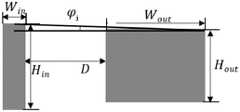
根据以上目标参数及耦入光栅与耦出光栅之间的预定间距D可以确定横向及竖向耦入光栅的尺寸大小,其示意如图4所示,公式如下:According to the above target parameters and the predetermined spacing D between the coupling-in grating and the coupling-out grating, the size of the horizontal and vertical coupling-in gratings can be determined, as shown in Figure 4, and the formula is as follows:


由以上公式可以看出,由于准直透镜组的出瞳口径大小已经确定横向及竖向耦入光栅的尺寸确定;ERF出瞳距一般按照人眼的正常观看距离确定,18mm左右;耦入光栅与耦出光栅之间的距离D值与FOV或Eyebox大小成反比,D值越大,FOV或Eyebox值越小。It can be seen from the above formula that since the exit pupil diameter of the collimating lens group has been determined, the size of the horizontal and vertical coupling grating is determined; the ERF exit pupil distance is generally determined according to the normal viewing distance of the human eye, about 18mm; the coupling grating The distance D between the outcoupling grating is inversely proportional to the FOV or Eyebox size, the larger the D value, the smaller the FOV or Eyebox value.
因此,本方案中采用减小D的方案,在准直透镜组与耦入光栅之间加入全反射镜,将光路折转,在不影响像质的前提下,既可以满足人体工程学设计,又可以增大FOV及Eyebox大小,增强视觉体验。Therefore, in this scheme, the scheme of reducing D is adopted, and a total reflection mirror is added between the collimating lens group and the coupling grating to deflect the optical path, which can meet the ergonomic design without affecting the image quality. It can also increase the FOV and Eyebox size to enhance the visual experience.
本公开实施例还提供了一种AR眼镜,其至少包括本公开上述实施例中的衍射光波导AR系统。当然,其不仅限于AR眼镜,也可以是AR头戴设备等。Embodiments of the present disclosure also provide AR glasses, which at least include the diffractive optical waveguide AR system in the foregoing embodiments of the present disclosure. Of course, it is not limited to AR glasses, but can also be AR headsets and the like.
本公开实施例还提供了一种衍射光波导AR系统的配置方法,用于上述的衍射光波导AR系统,其可以包括如下过程:An embodiment of the present disclosure also provides a configuration method of a diffractive optical waveguide AR system, which is used for the above-mentioned diffractive optical waveguide AR system, which may include the following process:
(1)确定目标参数,其中,目标参数至少包括:眼动范围Eye Box、瞳距ERF、视场区域FOV;(1) Determine the target parameters, wherein the target parameters include at least: Eye Box, pupillary distance ERF, field of view FOV;
(2)根据目标参数确定耦出光栅在人眼平视时的宽度和高度;(2) Determine the width and height of the outcoupling grating when the human eye is looking at the eye level according to the target parameters;
(3)根据耦入光栅的入射光的入射方位角和入射衍射角、耦入光栅的周期、所述入射光的波长确定耦入光栅的出射光的出射方位角;(3) determine the exit azimuth angle of the outgoing light coupled into the grating according to the incident azimuth and incident diffraction angle of the incident light coupled into the grating, the period of the coupled grating, and the wavelength of the incident light;
(4)根据耦出光栅的宽度和高度、所述出射方位角、耦入光栅和耦出光栅之间的预定间距,确定耦入光栅的宽度和高度。(4) Determine the width and height of the incoupling grating according to the width and height of the outcoupling grating, the outgoing azimuth angle, and the predetermined distance between the incoupling grating and the outcoupling grating.
实现时,根据目标参数确定耦出光栅在人眼平视时的宽度和高度时,按照如下公式确定宽度Wout和高度Hout:During implementation, when determining the width and height of the outcoupling grating at human eye level according to the target parameters, the width Wout and height Hout are determined according to the following formula:
Wout=EyeboxW+2ERF×tan(FOVW/2);Wout = EyeboxW +2ERF×tan(FOVW /2);
Hout=EyeboxH+2ERF×tan(FOVH/2);Hout = EyeboxH +2ERF×tan(FOVH /2);
其中,EyeboxW为眼动范围宽度,EyeboxH为眼动范围高度,ERF为瞳距,FOVW为视场区域宽度,FOVH为视场区域高度。Among them, EyeboxW is the width of the eye movement range, EyeboxH is the height of the eye movement range, ERF is the interpupillary distance, FOVW is the width of the field of view, and FOVH is the height of the field of view.
实现时,根据耦入光栅的入射光的入射方位角和入射衍射角、耦入光栅的周期、所述入射光的波长确定耦入光栅的出射光的出射方位角时,根据耦入光栅的结构及入射光的波矢图确定出入射光的波矢公式,根据入射光的波矢公式和光波导板的折射率确定入射光经过耦入光栅后的出射光的波矢公式,根据出射光的波矢公式确定出射方位角,当然,还可以确定出射衍射角。公式如下:When implementing, according to the incident azimuth angle and incident diffraction angle of the incident light coupled into the grating, the period of the coupled grating, and the wavelength of the incident light to determine the exit azimuth angle of the outgoing light coupled into the grating, according to the structure of the coupled grating and the wave vector diagram of the incident light to determine the wave vector formula of the incident light, according to the wave vector formula of the incident light and the refractive index of the optical waveguide plate to determine the wave vector formula of the outgoing light after the incident light is coupled into the grating, according to the wave vector of the outgoing light The formula determines the outgoing azimuth angle, and of course, the outgoing diffraction angle can also be determined. The formula is as follows:


其中,根据耦出光栅的宽度和高度、衍射角和方位角、预定间距和目标参数,确定耦入光栅的宽度和高度时,可以按照如下公式确定耦入光栅的宽度Win和高度Hin:Wherein, when determining the width and height of the coupled-in grating according to the width and height of the coupled-out grating, diffraction angle and azimuth, predetermined spacing and target parameters, the width Win and the height Hin of the coupled-in grating can be determined according to the following formula:


此外,尽管已经在本文中描述了示例性实施例,其范围包括任何和所有基于本公开的具有等同元件、修改、省略、组合(例如,各种实施例交叉的方案)、改编或改变的实施例。权利要求书中的元件将被基于权利要求中采用的语言宽泛地解释,并不限于在本说明书中或本申请的实施期间所描述的示例,其示例将被解释为非排他性的。因此,本说明书和示例旨在仅被认为是示例,真正的范围和精神由以下权利要求以及其等同物的全部范围所指示。Furthermore, while exemplary embodiments have been described herein, the scope includes any and all implementations having equivalent elements, modifications, omissions, combinations (eg, cross-cutting aspects of various embodiments), adaptations, or changes based on this disclosure. example. Elements in the claims are to be interpreted broadly based on the language employed in the claims and are not limited to examples described in this specification or during the practice of the application, which examples are to be construed as non-exclusive. It is therefore intended that the specification and examples be considered as illustrations only, with a true scope and spirit being indicated by the following claims, along with their full scope of equivalents.
以上描述旨在是说明性的而不是限制性的。例如,上述示例(或其一个或更多方案)可以彼此组合使用。例如本领域普通技术人员在阅读上述描述时可以使用其它实施例。另外,在上述具体实施方式中,各种特征可以被分组在一起以简单化本公开。这不应解释为一种不要求保护的公开的特征对于任一权利要求是必要的意图。相反,本公开的主题可以少于特定的公开的实施例的全部特征。从而,以下权利要求书作为示例或实施例在此并入具体实施方式中,其中每个权利要求独立地作为单独的实施例,并且考虑这些实施例可以以各种组合或排列彼此组合。本公开的范围应参照所附权利要求以及这些权利要求赋权的等同形式的全部范围来确定。The above description is intended to be illustrative rather than restrictive. For example, the above examples (or one or more aspects thereof) may be used in combination with each other. For example, other embodiments may be used by those of ordinary skill in the art upon reading the above description. Additionally, in the above Detailed Description, various features may be grouped together in order to simplify the disclosure. This is not to be interpreted as intending that an unclaimed disclosed feature is essential to any claim. Rather, disclosed subject matter may lie in less than all features of a particular disclosed embodiment. Thus, the following claims are hereby incorporated into the detailed description as examples or embodiments, where each claim stands on its own as a separate embodiment, and it is contemplated that these embodiments may be combined with each other in various combinations or permutations. The scope of the disclosure should be determined with reference to the appended claims, along with the full scope of equivalents to which such claims are entitled.
以上对本公开多个实施例进行了详细说明,但本公开不限于这些具体的实施例,本领域技术人员在本公开构思的基础上,能够做出多种变型和修改实施例,这些变型和修改都应落入本公开所要求保护的范围之内。Multiple embodiments of the present disclosure have been described in detail above, but the present disclosure is not limited to these specific embodiments. Those skilled in the art can make various variations and modifications on the basis of the concept of the disclosure. These variations and modifications All should fall within the scope of protection claimed by the present disclosure.
Claims (7)


Priority Applications (1)
| Application Number | Priority Date | Filing Date | Title |
|---|---|---|---|
| CN202111019613.6ACN113777785B (en) | 2021-09-01 | 2021-09-01 | Diffraction optical waveguide AR system, AR glasses and configuration method of the system |
Applications Claiming Priority (1)
| Application Number | Priority Date | Filing Date | Title |
|---|---|---|---|
| CN202111019613.6ACN113777785B (en) | 2021-09-01 | 2021-09-01 | Diffraction optical waveguide AR system, AR glasses and configuration method of the system |
Publications (2)
| Publication Number | Publication Date |
|---|---|
| CN113777785A CN113777785A (en) | 2021-12-10 |
| CN113777785Btrue CN113777785B (en) | 2022-11-22 |
Family
ID=78840528
Family Applications (1)
| Application Number | Title | Priority Date | Filing Date |
|---|---|---|---|
| CN202111019613.6AActiveCN113777785B (en) | 2021-09-01 | 2021-09-01 | Diffraction optical waveguide AR system, AR glasses and configuration method of the system |
Country Status (1)
| Country | Link |
|---|---|
| CN (1) | CN113777785B (en) |
Families Citing this family (6)
| Publication number | Priority date | Publication date | Assignee | Title |
|---|---|---|---|---|
| CN114779396A (en)* | 2022-04-27 | 2022-07-22 | 歌尔股份有限公司 | Optical waveguide systems and augmented reality devices |
| CN114815024B (en)* | 2022-05-19 | 2023-08-08 | 南京工业职业技术大学 | Exposure area calculation method for batch preparation of holographic diffraction waveguides and application thereof |
| CN117148593B (en)* | 2023-10-31 | 2024-02-20 | 深圳市光舟半导体技术有限公司 | AR device |
| CN119376108A (en)* | 2024-02-01 | 2025-01-28 | 迈特创新私人有限公司 | Glasses image position calibration system, method, device and AR glasses |
| CN117760705B (en)* | 2024-02-22 | 2024-05-14 | 武汉精立电子技术有限公司 | AR product eyebox measurement method and system |
| CN117930424B (en)* | 2024-03-22 | 2024-06-11 | 宁波舜宇光电信息有限公司 | AR diffraction waveguide sheet, design method and AR device |
Family Cites Families (3)
| Publication number | Priority date | Publication date | Assignee | Title |
|---|---|---|---|---|
| US7418170B2 (en)* | 2004-03-29 | 2008-08-26 | Sony Corporation | Optical device and virtual image display device |
| US20160231567A1 (en)* | 2015-02-09 | 2016-08-11 | Pasi Saarikko | Display System |
| CN106842397B (en)* | 2017-01-05 | 2020-07-17 | 苏州苏大维格光电科技股份有限公司 | A resin holographic waveguide lens, a preparation method thereof, and a three-dimensional display device |
- 2021
- 2021-09-01CNCN202111019613.6Apatent/CN113777785B/enactiveActive
Also Published As
| Publication number | Publication date |
|---|---|
| CN113777785A (en) | 2021-12-10 |
Similar Documents
| Publication | Publication Date | Title |
|---|---|---|
| CN113777785B (en) | Diffraction optical waveguide AR system, AR glasses and configuration method of the system | |
| KR102850187B1 (en) | Optical array for display | |
| US10955676B2 (en) | Head mounted imaging apparatus with optical coupling | |
| JP2024020240A (en) | Compact head-mounted display system that displays uniform images | |
| KR102266506B1 (en) | Spectacle lens for a display device which can be placed on the head of a user and which generates an image, and display device with such a spectacle lens | |
| FI128407B (en) | Projection lens and waveguide display device | |
| JP6720315B2 (en) | Imaging light guide with reflective conversion array | |
| US20240411142A1 (en) | Pupil relay system | |
| WO2015154643A1 (en) | Transmissive glasses display | |
| US11422371B2 (en) | Augmented reality (AR) display | |
| CN113574442B (en) | Optical system for generating virtual image and intelligent glasses | |
| US12249141B2 (en) | Method and system for pupil separation in a diffractive eyepiece waveguide display | |
| JP2018054672A (en) | Head-mounted display device | |
| CN219349182U (en) | Optical waveguide and near-to-eye display device | |
| JP2025502162A (en) | Apparatus and method for directing light to multiple in-coupler waveguides - Patents.com | |
| US20230011557A1 (en) | Display device | |
| CN116209941A (en) | Compensated diffractive waveguides for off-axis in-coupling and observation | |
| CN219609272U (en) | Optical waveguide and near-to-eye display device | |
| WO2023220133A1 (en) | Dual index waveguide stack | |
| CN115857177A (en) | Augmented reality display device | |
| CN117148594B (en) | Display assembly and AR equipment | |
| JP2025090917A (en) | Optical system and display device | |
| JP2025134135A (en) | Light guide member, optical system and display device | |
| CN113050275A (en) | Near-to-eye display device | |
| JP2001209002A (en) | Virtural image viewing optical system |
Legal Events
| Date | Code | Title | Description |
|---|---|---|---|
| PB01 | Publication | ||
| PB01 | Publication | ||
| SE01 | Entry into force of request for substantive examination | ||
| SE01 | Entry into force of request for substantive examination | ||
| GR01 | Patent grant | ||
| GR01 | Patent grant |