CN113776457A - Method and device for correction of profile measurement error of curved rail based on combination of virtual and real - Google Patents
Method and device for correction of profile measurement error of curved rail based on combination of virtual and realDownload PDFInfo
- Publication number
- CN113776457A CN113776457ACN202111011667.8ACN202111011667ACN113776457ACN 113776457 ACN113776457 ACN 113776457ACN 202111011667 ACN202111011667 ACN 202111011667ACN 113776457 ACN113776457 ACN 113776457A
- Authority
- CN
- China
- Prior art keywords
- rail
- coordinate system
- plane
- virtual
- image
- Prior art date
- Legal status (The legal status is an assumption and is not a legal conclusion. Google has not performed a legal analysis and makes no representation as to the accuracy of the status listed.)
- Granted
Links
- 238000005259measurementMethods0.000titleclaimsabstractdescription70
- 238000000034methodMethods0.000titleclaimsabstractdescription66
- 238000012937correctionMethods0.000titleclaimsabstractdescription21
- 238000005457optimizationMethods0.000claimsabstractdescription34
- 230000006870functionEffects0.000claimsdescription37
- 239000011159matrix materialSubstances0.000claimsdescription28
- 230000004927fusionEffects0.000claimsdescription19
- 238000013519translationMethods0.000claimsdescription18
- 238000004590computer programMethods0.000claimsdescription17
- 239000000284extractSubstances0.000claimsdescription9
- 238000003860storageMethods0.000claimsdescription9
- 230000005484gravityEffects0.000claimsdescription2
- 238000010586diagramMethods0.000description30
- 230000033001locomotionEffects0.000description30
- 230000008569processEffects0.000description12
- 238000004891communicationMethods0.000description5
- 238000012545processingMethods0.000description4
- 238000005096rolling processMethods0.000description4
- 238000005516engineering processMethods0.000description3
- 238000004088simulationMethods0.000description3
- 230000008859changeEffects0.000description2
- 238000012986modificationMethods0.000description2
- 230000004048modificationEffects0.000description2
- 238000005070samplingMethods0.000description2
- 238000005452bendingMethods0.000description1
- 230000009286beneficial effectEffects0.000description1
- 238000004364calculation methodMethods0.000description1
- 238000001514detection methodMethods0.000description1
- 238000011156evaluationMethods0.000description1
- 238000000605extractionMethods0.000description1
- 230000004886head movementEffects0.000description1
- 238000005286illuminationMethods0.000description1
- 238000003384imaging methodMethods0.000description1
- 230000006872improvementEffects0.000description1
- 238000004519manufacturing processMethods0.000description1
- 230000003287optical effectEffects0.000description1
- 238000011160researchMethods0.000description1
- 230000002194synthesizing effectEffects0.000description1
- 238000012546transferMethods0.000description1
Images


Classifications
- G—PHYSICS
- G01—MEASURING; TESTING
- G01B—MEASURING LENGTH, THICKNESS OR SIMILAR LINEAR DIMENSIONS; MEASURING ANGLES; MEASURING AREAS; MEASURING IRREGULARITIES OF SURFACES OR CONTOURS
- G01B11/00—Measuring arrangements characterised by the use of optical techniques
- G01B11/24—Measuring arrangements characterised by the use of optical techniques for measuring contours or curvatures
- G01B11/2433—Measuring arrangements characterised by the use of optical techniques for measuring contours or curvatures for measuring outlines by shadow casting
- Y—GENERAL TAGGING OF NEW TECHNOLOGICAL DEVELOPMENTS; GENERAL TAGGING OF CROSS-SECTIONAL TECHNOLOGIES SPANNING OVER SEVERAL SECTIONS OF THE IPC; TECHNICAL SUBJECTS COVERED BY FORMER USPC CROSS-REFERENCE ART COLLECTIONS [XRACs] AND DIGESTS
- Y02—TECHNOLOGIES OR APPLICATIONS FOR MITIGATION OR ADAPTATION AGAINST CLIMATE CHANGE
- Y02T—CLIMATE CHANGE MITIGATION TECHNOLOGIES RELATED TO TRANSPORTATION
- Y02T10/00—Road transport of goods or passengers
- Y02T10/10—Internal combustion engine [ICE] based vehicles
- Y02T10/40—Engine management systems
Landscapes
- Physics & Mathematics (AREA)
- General Physics & Mathematics (AREA)
- Length Measuring Devices By Optical Means (AREA)
Abstract
Translated fromChinese
Description
Translated fromChinese技术领域technical field
本发明属于铁路轨道检测技术领域,涉及一种基于虚实结合的曲线段钢轨轮廓测量误差修正方法和装置。The invention belongs to the technical field of railway track detection, and relates to a method and a device for correcting the measurement error of a curved section rail profile based on the combination of virtual and real.
背景技术Background technique
钢轨轮廓测量组件一般安装在车体下方或转向架上,与车体或者转向架刚性连接。一般情况下,车辆经过直线路段时,钢轨轮廓测量组件的激光平面垂直于钢轨的局部纵向,此时,测量结果是钢轨的横断面轮廓。而车辆经过曲线路段时,由于轮轨冲角的增大,钢轨轮廓测量组件的激光平面与钢轨纵向不再满足垂直的关系,此时,测量结果是钢轨的斜断面轮廓数据,而非横断面轮廓数据,造成测量轮廓存在一定程度的畸变,使测量轮廓中垂直磨耗点和侧面磨耗点的定位产生了一定的偏差,降低了钢轨磨耗测量精度。The rail profile measuring component is generally installed under the car body or on the bogie, and is rigidly connected to the car body or the bogie. Under normal circumstances, when the vehicle passes through a straight section, the laser plane of the rail profile measuring component is perpendicular to the local longitudinal direction of the rail, and at this time, the measurement result is the cross-sectional profile of the rail. When the vehicle passes through the curved road section, due to the increase of the wheel-rail attack angle, the laser plane of the rail profile measuring component and the longitudinal direction of the rail no longer satisfy the vertical relationship. At this time, the measurement result is the profile data of the inclined section of the rail, not the cross section. The profile data causes a certain degree of distortion in the measurement profile, which causes a certain deviation in the positioning of the vertical wear point and the side wear point in the measurement profile, which reduces the measurement accuracy of rail wear.
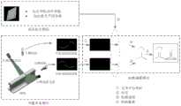
在现有技术中,线结构光轮廓测量技术基于三角测量原理,可以实时获取被测物的轮廓信息,具有高速、高精度和非接触的特点,是钢轨廓形动态检测的主流方式。图1为现有技术中线结构光钢轨轮廓测量原理图,在钢轨左右两侧各有一套由相机、镜头和线激光器组成的激光摄像组件,两套组件的激光平面共面安装,分别用于获取钢轨左右半断面轮廓数据,由标定参数将半断面轮廓进行拼接,从而得到钢轨全断面轮廓。配合扫描运动,即可实现对整个钢轨的轮廓测量。In the prior art, the linear structured light profile measurement technology is based on the principle of triangulation, and can obtain the profile information of the measured object in real time. Fig. 1 is the schematic diagram of the profile measurement of the centerline structured light rail in the prior art, on the left and right sides of the rail there is a set of laser imaging components consisting of a camera, a lens and a line laser, and the laser planes of the two sets of components are installed coplanarly, respectively for obtaining The profile data of the left and right half-sections of the rail are spliced by the calibration parameters to obtain the full-section profile of the rail. With the scanning motion, the profile measurement of the entire rail can be realized.
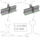
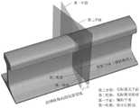
在上述方法中,车辆经过曲线路段时,轮对和车体要沿着线路弯曲的方向调整行进方向,如图2所示,图2为线结构光轮廓测量技术中曲线路段车体与钢轨局部纵向的关系的示意图,此时,由于轮轨冲角的增大,车体方向与钢轨局部纵向的夹角也增大,受此影响,激光平面与钢轨局部纵向不再满足垂直的关系。由图2可以看出,钢轨轮廓测量组件安装在车体上,尤其是车体端部时,受到的影响更大。In the above method, when the vehicle passes through the curved road section, the wheelset and the vehicle body should adjust the traveling direction along the direction of the line bending, as shown in Figure 2, which is the part of the vehicle body and the rail on the curved road section in the line structured light profile measurement technology A schematic diagram of the longitudinal relationship. At this time, due to the increase of the wheel-rail attack angle, the angle between the direction of the car body and the local longitudinal direction of the rail also increases. Affected by this, the laser plane and the local longitudinal direction of the rail no longer satisfy the vertical relationship. It can be seen from Figure 2 that when the rail profile measuring component is installed on the car body, especially the end of the car body, it is more affected.
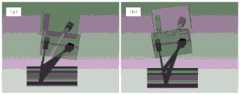
另外,激光平面相对于钢轨存在点头运动,摇头运动、侧滚运动以及绕三个轴的平移,其中,侧滚运动以及绕三个轴的平移不改变激光平面与钢轨纵向的垂直关系,因此,钢轨轮廓测量结果不存在畸变,相反,激光平面相对于钢轨的点头运动和摇头运动改变了激光平面与钢轨纵向的垂直关系,如图3所示为行车过程中激光平面相对钢轨的运动示意图,图3中的(a)为点头运动,图3中的(b)为摇头运动,这种条件下,测量结果是钢轨的斜断面轮廓,相比于正常轮廓存在一定的畸变,即沿某个方向出现了拉伸放大。对于激光平面的点头运动,相当于将正常钢轨轮廓沿Y轴进行了拉伸,对于激光平面的摇头运动,相当于将正常钢轨轮廓沿X轴进行了拉伸。In addition, the laser plane has nodding motion, shaking motion, rolling motion and translation around three axes relative to the rail, wherein the rolling motion and translation around the three axes do not change the vertical relationship between the laser plane and the longitudinal direction of the rail, therefore, There is no distortion in the measurement results of the rail profile. On the contrary, the nodding and shaking movements of the laser plane relative to the rail change the vertical relationship between the laser plane and the longitudinal direction of the rail. Figure 3 is a schematic diagram of the movement of the laser plane relative to the rail during driving. 3 (a) is the nodding motion, and (b) in Figure 3 is the shaking motion. Under this condition, the measurement result is the profile of the inclined section of the rail, which has a certain distortion compared with the normal profile, that is, along a certain direction. Stretch magnification occurs. For the nodding motion of the laser plane, it is equivalent to stretching the normal rail profile along the Y axis, and for the shaking motion of the laser plane, it is equivalent to stretching the normal rail profile along the X axis.
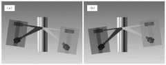
为了定量分析激光平面的点头运动和摇头运动对钢轨轮廓测量结果的影响,利用钢轨轮廓全断面测量系统仿真模型模拟行车过程中激光平面的点头运动和摇头运动,如图4所示为模拟行车过程中激光平面与钢轨纵向垂直的示意图,模拟测量标准60kg/m钢轨,得到标准钢轨的垂直磨耗和侧面磨耗测量结果。建立如图4中的(a)所示的激光平面坐标系,图4中的(a)为俯视图,图4中的(b)为左视图,其中,XOY平面位于激光平面上,X轴与轨距方向相同,Y轴垂直钢轨纵向。激光平面绕X轴旋转记为RX,通过绕X轴旋转模拟点头运动,如图5所示为模拟行车过程中激光平面点头运动的示意图,图5中的(a)RX=-5°,图5中的(b)RX=5°。绕Y轴旋转记为RY,通过绕Y轴旋转模拟摇头运动,如图6所示为模拟行车过程中激光平面摇头运动的示意图。模拟过程中,设置点头角度从RX=-5°(图6中的(a))到RX=5°(图6中的(b)),步长1°,摇头运动的采样间隔与点头运动相同。In order to quantitatively analyze the influence of the nodding and shaking motions of the laser plane on the measurement results of the rail profile, the full-section measurement system simulation model of the rail profile is used to simulate the nodding and shaking motions of the laser plane during the driving process, as shown in Figure 4 for the simulated driving process. The schematic diagram of the laser plane perpendicular to the longitudinal direction of the rail, simulates the measurement of a standard 60kg/m rail, and obtains the measurement results of vertical wear and side wear of the standard rail. Establish a laser plane coordinate system as shown in (a) in Figure 4, (a) in Figure 4 is a top view, and (b) in Figure 4 is a left view, where the XOY plane is located on the laser plane, and the X axis and the The gauge direction is the same, and the Y axis is vertical to the longitudinal direction of the rail. The rotation of the laser plane around the X-axis is recorded as RX, and the nodding motion is simulated by rotating around the X-axis. Figure 5 is a schematic diagram of the nodding motion of the laser plane during the simulation of the driving process. (a) RX=-5° in Figure 5, Figure (b) RX = 5° in 5. The rotation around the Y axis is recorded as RY, and the shaking movement is simulated by rotating around the Y axis. Figure 6 is a schematic diagram of simulating the shaking movement of the laser plane during driving. During the simulation, set the nodding angle from RX=-5° ((a) in Fig. 6) to RX=5° ((b) in Fig. 6), the step size is 1°, the sampling interval of the shaking head movement and the nodding movement same.
图7所示为钢轨激光断面图像和轮廓测量结果,即点头角-5°(图7中的(a))和摇头角-5°(图7中的(b))时钢轨激光断面图像和钢轨轮廓测量结果,其中横断面轮廓指的是激光平面与钢轨纵向垂直时的测量钢轨轮廓,可以看出,激光平面的点头运动造成测量轮廓沿垂向进行了拉伸,激光平面的摇头运动造成测量轮廓沿横向进行了拉伸。Figure 7 shows the rail laser cross-section image and profile measurement results, that is, the rail laser cross-section image when the nod angle is -5° ((a) in Figure 7) and the yaw angle is -5° (Figure 7 (b)). The measurement results of the rail profile, in which the cross-sectional profile refers to the profile of the measured rail when the laser plane is perpendicular to the longitudinal direction of the rail. It can be seen that the nodding motion of the laser plane causes the measurement profile to stretch in the vertical direction, and the shaking motion of the laser plane causes The measurement profile is stretched in the transverse direction.
图8为不同运动姿态下的标准钢轨磨耗测量结果,可以看出,激光平面点头运动和摇头运动均造成了钢轨的磨耗测量误差,其中,钢轨垂直磨耗测量误差对激光平面的点头运动较为敏感,随着点头角度的增大而迅速增大,而钢轨的侧面磨耗测量误差对激光平面的摇头运动较为敏感,随着摇头角度的增大而迅速增大。因此,必须采取相应的误差修正措施来保证曲线路段的钢轨轮廓测量精度。Figure 8 shows the measurement results of the standard rail wear under different motion attitudes. It can be seen that both the nodding motion and the shaking motion of the laser plane cause the wear measurement error of the rail. Among them, the vertical wear measurement error of the rail is more sensitive to the nodding motion of the laser plane. It increases rapidly with the increase of the nodding angle, and the measurement error of the lateral wear of the rail is more sensitive to the shaking motion of the laser plane, and increases rapidly with the increase of the shaking angle. Therefore, corresponding error correction measures must be taken to ensure the measurement accuracy of the rail profile of the curved road section.
发明内容SUMMARY OF THE INVENTION
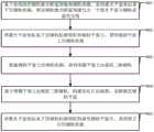
本发明实施例提出一种基于虚实结合的曲线段钢轨轮廓测量误差修正方法,用以对曲线段钢轨轮廓测量误差进行修正,修正精度高,该方法包括:The embodiment of the present invention proposes a method for correcting the profile measurement error of the curved section rail based on the combination of virtual and real, which is used to correct the profile measurement error of the curved section rail, and the correction accuracy is high. The method includes:
基于曲线段的钢轨激光断面图像和钢轨图像,获得激光平面坐标系下的钢轨轮廓,所述钢轨激光断面图像包含一个激光平面与钢轨表面的交线;Obtain the rail profile in the laser plane coordinate system based on the rail laser cross-section image and the rail image of the curved segment, and the rail laser cross-section image includes an intersection line between the laser plane and the rail surface;
将激光平面坐标系下的钢轨轮廓投影到辅助平面上,获得辅助平面上的钢轨轮廓;Project the rail profile in the laser plane coordinate system onto the auxiliary plane to obtain the rail profile on the auxiliary plane;
根据辅助平面上的钢轨轮廓,获得图像平面上的虚拟三维钢轨;According to the rail profile on the auxiliary plane, obtain the virtual 3D rail on the image plane;
基于图像平面上的虚拟三维钢轨,构建优化目标函数,求解最优辅助平面;Based on the virtual 3D rail on the image plane, construct the optimization objective function and solve the optimal auxiliary plane;
将激光平面坐标系下的钢轨轮廓投影到最优辅助平面内,获得修正后的钢轨轮廓。The rail profile in the laser plane coordinate system is projected into the optimal auxiliary plane to obtain the corrected rail profile.
本发明实施例提出一种基于虚实结合的曲线段钢轨轮廓测量误差修正装置,用以对曲线段钢轨轮廓测量误差进行修正,修正精度高,该装置包括:The embodiment of the present invention proposes a correction device for the profile measurement error of a curved section rail based on the combination of virtual and real, which is used to correct the profile measurement error of the curved section rail with high correction accuracy. The device includes:
第一钢轨轮廓获得模块,用于基于曲线段的钢轨激光断面图像和钢轨图像,获得激光平面坐标系下的钢轨轮廓,所述钢轨激光断面图像包含一个激光平面与钢轨表面的交线;The first rail profile obtaining module is used to obtain the rail profile in the laser plane coordinate system based on the rail laser cross-section image and the rail image of the curved segment, and the rail laser cross-section image includes an intersection line between the laser plane and the rail surface;
第二钢轨轮廓获得模块,用于将激光平面坐标系下的钢轨轮廓投影到辅助平面上,获得辅助平面上的钢轨轮廓;The second rail profile obtaining module is used to project the rail profile in the laser plane coordinate system onto the auxiliary plane to obtain the rail profile on the auxiliary plane;
虚拟三维钢轨获得模块,用于根据辅助平面上的钢轨轮廓,获得图像平面上的虚拟三维钢轨;The virtual 3D rail acquisition module is used to obtain the virtual 3D rail on the image plane according to the rail profile on the auxiliary plane;
最优辅助平面求解模块,用于基于图像平面上的虚拟三维钢轨,构建优化目标函数,求解最优辅助平面;The optimal auxiliary plane solving module is used to construct the optimization objective function based on the virtual three-dimensional rail on the image plane, and solve the optimal auxiliary plane;
修正模块,用于将激光平面坐标系下的钢轨轮廓投影到最优辅助平面内,获得修正后的钢轨轮廓。The correction module is used to project the rail profile in the laser plane coordinate system into the optimal auxiliary plane to obtain the corrected rail profile.
本发明实施例还提出了一种计算机设备,包括存储器、处理器及存储在存储器上并可在处理器上运行的计算机程序,所述处理器执行所述计算机程序时实现上述基于虚实结合的曲线段钢轨轮廓测量误差修正。An embodiment of the present invention also provides a computer device, including a memory, a processor, and a computer program stored in the memory and running on the processor, where the processor implements the above-mentioned virtual-real combination-based curve when executing the computer program Section rail profile measurement error correction.
本发明实施例还提出了一种计算机可读存储介质,所述计算机可读存储介质存储有执行上述基于虚实结合的曲线段钢轨轮廓测量误差修正方法的计算机程序。An embodiment of the present invention further provides a computer-readable storage medium, where the computer-readable storage medium stores a computer program for executing the above-mentioned method for correcting the measurement error of a rail profile of a curved section based on the combination of virtual and real.
在本发明实施例中,基于曲线段的钢轨激光断面图像和钢轨图像,获得激光平面坐标系下的钢轨轮廓,所述钢轨激光断面图像包含一个激光平面与钢轨表面的交线;将激光平面坐标系下的钢轨轮廓投影到辅助平面上,获得辅助平面上的钢轨轮廓;根据辅助平面上的钢轨轮廓,获得图像平面上的虚拟三维钢轨;基于图像平面上的虚拟三维钢轨,构建优化目标函数,求解最优辅助平面;将激光平面坐标系下的钢轨轮廓投影到最优辅助平面内,获得修正后的钢轨轮廓。在上述过程中,通过优先构建虚拟三维钢轨,进而构建优化目标函数,求解最优辅助平面;将激光平面坐标系下的钢轨轮廓投影到最优辅助平面内,获得修正后的钢轨轮廓,可得到精度非常高的钢轨轮廓。In the embodiment of the present invention, the rail profile in the laser plane coordinate system is obtained based on the rail laser cross-section image and the rail image of the curved segment, and the rail laser cross-section image includes an intersection line between the laser plane and the rail surface; the laser plane coordinates The rail profile under the system is projected onto the auxiliary plane to obtain the rail profile on the auxiliary plane; according to the rail profile on the auxiliary plane, the virtual 3D rail on the image plane is obtained; based on the virtual 3D rail on the image plane, the optimization objective function is constructed, Solve the optimal auxiliary plane; project the rail profile in the laser plane coordinate system into the optimal auxiliary plane to obtain the corrected rail profile. In the above process, by first constructing a virtual three-dimensional rail, and then constructing an optimization objective function, the optimal auxiliary plane is solved; the rail profile in the laser plane coordinate system is projected into the optimal auxiliary plane to obtain the revised rail profile, which can be obtained Very precise rail profile.
附图说明Description of drawings
为了更清楚地说明本发明实施例或现有技术中的技术方案,下面将对实施例或现有技术描述中所需要使用的附图作简单地介绍,显而易见地,下面描述中的附图仅仅是本发明的一些实施例,对于本领域普通技术人员来讲,在不付出创造性劳动的前提下,还可以根据这些附图获得其他的附图。在附图中:In order to explain the embodiments of the present invention or the technical solutions in the prior art more clearly, the following briefly introduces the accompanying drawings that need to be used in the description of the embodiments or the prior art. Obviously, the accompanying drawings in the following description are only These are some embodiments of the present invention. For those of ordinary skill in the art, other drawings can also be obtained according to these drawings without creative efforts. In the attached image:
图1为现有技术中线结构光钢轨轮廓测量原理图;Fig. 1 is a schematic diagram of the measurement principle of the profile of a central line structured light rail in the prior art;
图2为线结构光轮廓测量技术中曲线路段车体与钢轨局部纵向的关系的示意图图;FIG. 2 is a schematic diagram of the relationship between the car body of the curved road section and the local longitudinal direction of the rail in the line structured light profile measurement technology;
图3为行车过程中激光平面相对钢轨的运动示意图;Figure 3 is a schematic diagram of the movement of the laser plane relative to the rail during the driving process;
图4为模拟行车过程中激光平面与钢轨纵向垂直的示意图;Fig. 4 is the schematic diagram that the laser plane is perpendicular to the longitudinal direction of the rail in the simulated driving process;
图5为模拟行车过程中激光平面点头运动的示意图;Fig. 5 is a schematic diagram of simulating laser plane nodding motion during driving;
图6为模拟行车过程中激光平面摇头运动的示意图;Fig. 6 is the schematic diagram of the laser plane shaking his head during the simulated driving process;
图7为钢轨激光断面图像和轮廓测量结果;Fig. 7 is the laser cross-section image and profile measurement results of the rail;
图8为不同运动姿态下的标准钢轨磨耗测量结果;Figure 8 shows the measurement results of standard rail wear under different motion attitudes;
图9为本发明实施例中基于虚实结合的曲线段钢轨轮廓测量误差修正方法的流程图;9 is a flow chart of a method for correcting the measurement error of the profile measurement of a curved section rail based on the combination of virtual and real in an embodiment of the present invention;
图10为本发明实施例中曲线段实际激光平面与辅助激光平面的示意图;10 is a schematic diagram of the actual laser plane and the auxiliary laser plane of the curved segment in the embodiment of the present invention;
图11为本发明实施例中钢轨激光断面图像和钢轨图像融合示意图;11 is a schematic diagram of fusion of a rail laser cross-sectional image and a rail image in an embodiment of the present invention;
图12为本发明实施例中钢轨特征线的示意图;12 is a schematic diagram of a rail characteristic line in an embodiment of the present invention;
图13为本发明实施例中虚拟三维钢轨的边缘特征线与实际钢轨的钢轨特征线的重合度的评估方法示意图;13 is a schematic diagram of a method for evaluating the coincidence degree of the edge feature line of the virtual three-dimensional rail and the rail feature line of the actual rail in an embodiment of the present invention;
图14为本发明实施例中基于虚实结合的曲线段钢轨轮廓测量误差修正方法的详细流程图;14 is a detailed flowchart of a method for correcting the profile measurement error of a curved section rail based on a combination of virtual and real in an embodiment of the present invention;
图15为本发明实施例中基于虚实结合的曲线段钢轨轮廓测量误差修正装置的示意图;15 is a schematic diagram of a device for correcting the profile measurement error of a curved section rail based on the combination of virtual and real in an embodiment of the present invention;
图16为本发明实施例中计算机设备的示意图。FIG. 16 is a schematic diagram of a computer device in an embodiment of the present invention.
具体实施方式Detailed ways
为使本发明实施例的目的、技术方案和优点更加清楚明白,下面结合附图对本发明实施例做进一步详细说明。在此,本发明的示意性实施例及其说明用于解释本发明,但并不作为对本发明的限定。In order to make the purposes, technical solutions and advantages of the embodiments of the present invention more clearly understood, the embodiments of the present invention will be further described in detail below with reference to the accompanying drawings. Here, the exemplary embodiments of the present invention and their descriptions are used to explain the present invention, but not to limit the present invention.
在本说明书的描述中,所使用的“包含”、“包括”、“具有”、“含有”等,均为开放性的用语,即意指包含但不限于。参考术语“一个实施例”、“一个具体实施例”、“一些实施例”、“例如”等的描述意指结合该实施例或示例描述的具体特征、结构或者特点包含于本发明的至少一个实施例或示例中。在本说明书中,对上述术语的示意性表述不一定指的是相同的实施例或示例。而且,描述的具体特征、结构或者特点可以在任何的一个或多个实施例或示例中以合适的方式结合。各实施例中涉及的步骤顺序用于示意性说明本发明的实施,其中的步骤顺序不作限定,可根据需要作适当调整。In the description of this specification, the use of "comprising", "including", "having", "containing" and the like are all open-ended terms, that is, meaning including but not limited to. Descriptions with reference to the terms "one embodiment," "one specific embodiment," "some embodiments," "for example," etc. mean that a particular feature, structure, or characteristic described in connection with the embodiment or example is included in at least one of the present invention examples or examples. In this specification, schematic representations of the above terms do not necessarily refer to the same embodiment or example. Furthermore, the particular features, structures or characteristics described may be combined in any suitable manner in any one or more embodiments or examples. The sequence of steps involved in each embodiment is used to schematically illustrate the implementation of the present invention, and the sequence of steps therein is not limited, and can be appropriately adjusted as required.
图9为本发明实施例中基于虚实结合的曲线段钢轨轮廓测量误差修正方法的流程图,如图9所示,该方法包括:FIG. 9 is a flowchart of a method for correcting the profile measurement error of a curved section rail based on the combination of virtual and real in an embodiment of the present invention. As shown in FIG. 9 , the method includes:
步骤901,基于曲线段的钢轨激光断面图像和钢轨图像,获得激光平面坐标系下的钢轨轮廓,所述钢轨激光断面图像包含一个激光平面与钢轨表面的交线;
步骤902,将激光平面坐标系下的钢轨轮廓投影到辅助平面上,获得辅助平面上的钢轨轮廓;
步骤903,根据辅助平面上的钢轨轮廓,获得图像平面上的虚拟三维钢轨;
步骤904,基于图像平面上的虚拟三维钢轨,构建优化目标函数,求解最优辅助平面;
步骤905,将激光平面坐标系下的钢轨轮廓投影到最优辅助平面内,获得修正后的钢轨轮廓。Step 905: Project the rail profile in the laser plane coordinate system into the optimal auxiliary plane to obtain the corrected rail profile.
首先,介绍一下本发明实施例提出的方法的原理。First, the principle of the method proposed in the embodiment of the present invention is introduced.
在曲线段,由于激光平面与钢轨纵向不再垂直,系统得到了钢轨的斜断面轮廓数据,造成钢轨轮廓测量误差。由于激光平面旋转角度较小,在钢轨纵向局部邻域内的横断面轮廓形状接近。因此,若将钢轨的斜断面轮廓数据投影到与钢轨纵向垂直的辅助平面上,如图10所示为本发明实施例中曲线段实际激光平面与辅助激光平面的示意图,通过投影,实际激光平面上畸变的钢轨轮廓数据在辅助平面上被拉伸到正常情况,则辅助平面上的轮廓就是钢轨的横断面轮廓,从而实现曲线段由于激光平面与钢轨纵向不垂直导致的钢轨轮廓测量误差。In the curve section, since the laser plane is no longer perpendicular to the longitudinal direction of the rail, the system obtains the profile data of the inclined section of the rail, resulting in an error in the profile measurement of the rail. Due to the small rotation angle of the laser plane, the shape of the cross-sectional profile in the longitudinal local neighborhood of the rail is similar. Therefore, if the profile data of the oblique section of the rail is projected onto the auxiliary plane perpendicular to the longitudinal direction of the rail, Figure 10 is a schematic diagram of the actual laser plane and the auxiliary laser plane of the curve segment in the embodiment of the present invention. Through projection, the actual laser plane The upper distorted rail profile data is stretched to the normal condition on the auxiliary plane, then the profile on the auxiliary plane is the cross-sectional profile of the rail, so as to realize the rail profile measurement error caused by the non-perpendicular laser plane and the rail longitudinal direction in the curve segment.
在车辆行进过程中,如何获取钢轨纵向是修正此类轮廓测量误差的关键,为此,本发明实施例提出了基于虚实结合的曲线段钢轨轮廓测量误差修正方法,以钢轨半断面轮廓测量作为研究对象,钢轨全断面轮廓测量修正方法与此类似。根据钢轨实际测量轮廓数据以及激光平面坐标系在相机坐标系下的旋转矩阵


不同的辅助平面对应不同的虚拟钢轨,因此,以实际激光平面坐标系到辅助平面坐标系的旋转矩阵


当然,创建辅助平面坐标系时,可以将其原点与实际激光平面坐标系的原点重合,则Of course, when creating the auxiliary plane coordinate system, its origin can be coincident with the origin of the actual laser plane coordinate system, then

此外,激光平面相对钢轨的侧滚运动不影响两者的垂直关系,因此,实际激光平面坐标系到辅助平面坐标系的旋转矩阵

其中,in,


所述第一变量为绕激光平面坐标系的X轴的旋转量,所述第二变量为绕激光平面坐标系的X轴旋转后得到临时坐标系,再绕临时坐标系的Y轴的旋转量。因此,只需要求解两个变量α和β的值即可确定最优辅助平面。The first variable is the rotation amount around the X axis of the laser plane coordinate system, and the second variable is the rotation amount around the Y axis of the temporary coordinate system to obtain a temporary coordinate system after rotating around the X axis of the laser plane coordinate system. . Therefore, it is only necessary to solve for the values of the two variables α and β to determine the optimal auxiliary plane.
基于上述原理,下面给出进行修正的详细过程。Based on the above-mentioned principle, the detailed process of the correction is given below.
在一实施例中,基于曲线段的钢轨激光断面图像和钢轨图像,获得激光平面坐标系下的钢轨轮廓,包括:In one embodiment, based on the rail laser cross-section image and the rail image of the curved segment, the rail profile in the laser plane coordinate system is obtained, including:
将钢轨激光断面图像和钢轨图像融合,获得融合图像;Fusion of the rail laser cross-section image and rail image to obtain a fusion image;
从融合图像中提取钢轨激光断面图像的光条中心;Extract the center of the light bar of the rail laser cross-section image from the fusion image;
将光条中心像素坐标系下的光条中心变换至激光平面坐标系下,获得激光平面坐标系下的钢轨轮廓。Transform the center of the light bar in the pixel coordinate system of the center of the light bar to the laser plane coordinate system to obtain the rail profile in the laser plane coordinate system.
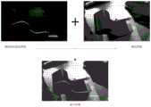
在上述实施例中,对于低速的应用情况,可以利用面阵相机通过短曝光获取钢轨激光断面图像,然后利用脉冲信号关闭激光器并通过较长曝光获取钢轨图像。对于高速的应用情况,可以采用与激光器波长不同的光源辅助照明,然后通过两个面阵相机分别获取钢轨激光断面图像和钢轨图像,并通过相机关联标定,将钢轨激光断面图像融合到钢轨图像中,形成融合图像。图11为本发明实施例中钢轨激光断面图像和钢轨图像融合示意图,采用如下方法的其中一种或任意组合,提取钢轨激光断面图像的光条中心:极值法,灰度重心法,模板匹配法,Steger法。记光条中心上任意一点Pi的像素坐标为In the above embodiment, for low-speed applications, an area scan camera can be used to obtain a rail laser cross-section image through short exposure, and then a pulse signal is used to turn off the laser and a longer exposure can be used to obtain the rail image. For high-speed applications, a light source with a different wavelength from the laser can be used to assist illumination, and then two area scan cameras are used to obtain the rail laser cross-section image and the rail image respectively, and through the camera correlation calibration, the rail laser cross-section image is merged into the rail image. , forming a fusion image. 11 is a schematic diagram of fusion of the rail laser cross-sectional image and the rail image in the embodiment of the present invention. One or any combination of the following methods is used to extract the center of the light bar of the rail laser cross-section image: extreme value method, gray center of gravity method, template matching method, Steger method. Note the pixel coordinates of any pointPi on the center of the light bar as
Pi=(ui,vi)T,i=1,2,3...n1 (5)Pi =(ui ,vi )T ,i =1,2,3...n1 (5)
其中,n1为钢轨轮廓点的数量。Among them, n1 is the number of rail profile points.
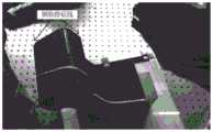
另外,还可以从融合图像中提取钢轨特征线,该钢轨特征线将在后续用到,钢轨特征线指的是钢轨图像中钢轨的左右边缘,图12为本发明实施例中钢轨特征线的示意图,左右边缘用于后续计算虚拟三维钢轨与实际钢轨轮廓的重合度。钢轨左右两侧边缘可通过常用的边缘提取方法得到,采用如下算子的其中一种或任意组合,提取钢轨图像的钢轨特征线:Sobel算子,Roberts算子,Laplacian算子,Canny算子。记通过Canny算子得到的钢轨特征线上任意一点Gi的像素坐标为In addition, the rail feature line can also be extracted from the fusion image, and the rail feature line will be used later. The rail feature line refers to the left and right edges of the rail in the rail image. FIG. 12 is a schematic diagram of the rail feature line in the embodiment of the present invention. , the left and right edges are used for subsequent calculation of the coincidence of the virtual 3D rail and the actual rail profile. The edges of the left and right sides of the rail can be obtained by common edge extraction methods. One or any combination of the following operators is used to extract the rail feature lines of the rail image: Sobel operator, Roberts operator, Laplacian operator, Canny operator. The pixel coordinates of any point Gi on the rail characteristic line obtained by the Canny operator are written as
Gi=(ui,vi)T,i=1,2,3...n2 (6)Gi =(ui ,vi )T ,i =1,2,3...n2 (6)
其中,n2为钢轨特征线上点的数量。Among them, n2 is the number of points on the rail characteristic line.
利用系统标定参数将光条中心像素坐标系下的光条中心变换至激光平面坐标系下,获得激光平面坐标系下的钢轨轮廓,所述钢轨轮廓上的任意一点

在一实施例中,将激光平面坐标系下的钢轨轮廓投影到辅助平面上,获得辅助平面上的钢轨轮廓,包括:In one embodiment, the rail profile in the laser plane coordinate system is projected onto the auxiliary plane to obtain the rail profile on the auxiliary plane, including:
根据激光平面坐标系到辅助平面坐标系的旋转矩阵,将激光平面坐标系下的钢轨轮廓变换到辅助平面坐标系下,得到辅助平面坐标系下的钢轨轮廓;According to the rotation matrix from the laser plane coordinate system to the auxiliary plane coordinate system, the rail profile in the laser plane coordinate system is transformed into the auxiliary plane coordinate system, and the rail profile in the auxiliary plane coordinate system is obtained;
将辅助平面坐标系下的钢轨轮廓投影到辅助平面内,获得辅助平面上的钢轨轮廓。Project the rail profile in the auxiliary plane coordinate system into the auxiliary plane to obtain the rail profile on the auxiliary plane.
首先,由激光平面坐标系lcs创建辅助平面坐标系acs,其中,acs的XOY平面就是辅助平面,Z轴与辅助平面垂直。由于acs的原点与lcs的重合,且激光平面侧滚运动不影响钢轨与激光平面的垂直度,因此,lcs到acs的旋转矩阵

然后,通过式(8)将


之后将辅助平面坐标系下的钢轨轮廓投影到辅助平面(辅助平面坐标系的XOY平面)内,令

在一实施例中,根据辅助平面上的钢轨轮廓,获得图像平面上的虚拟三维钢轨,包括:In one embodiment, obtaining a virtual three-dimensional rail on the image plane according to the rail profile on the auxiliary plane, including:
以辅助平面上的钢轨轮廓,沿辅助平面坐标系的Z轴方向创建等间距的虚拟轮廓,构建虚拟三维钢轨;Using the rail profile on the auxiliary plane, create equidistant virtual profiles along the Z-axis direction of the auxiliary plane coordinate system to construct a virtual three-dimensional rail;
计算相机坐标系到辅助平面坐标系的旋转矩阵和平移向量;Calculate the rotation matrix and translation vector from the camera coordinate system to the auxiliary plane coordinate system;
基于相机坐标系到辅助平面坐标系的旋转矩阵和平移向量,将虚拟三维钢轨变换到相机坐标系下,获得相机坐标系下的虚拟三维钢轨;Based on the rotation matrix and translation vector from the camera coordinate system to the auxiliary plane coordinate system, transform the virtual 3D rail into the camera coordinate system to obtain the virtual 3D rail in the camera coordinate system;
利用相机内参矩阵,将相机坐标系下的虚拟三维钢轨投影到图像平面上,获得图像平面上的虚拟三维钢轨。Using the camera internal parameter matrix, the virtual 3D rail in the camera coordinate system is projected onto the image plane to obtain the virtual 3D rail on the image plane.
在上述实施例中,以辅助平面上的钢轨轮廓为初始数据,沿辅助平面坐标系的Z轴方向创建等间距的虚拟轮廓,构建虚拟三维钢轨,记辅助平面内的轮廓点为虚拟三维钢轨的第0个轮廓,假设生成的虚拟钢轨的长度为l mm(l一般可取100mm),采样间隔为smm(s一般可取1mm),则虚拟三维钢轨轮廓的数量n3可表示为In the above-mentioned embodiment, the rail profile on the auxiliary plane is used as the initial data, and the equidistant virtual profiles are created along the Z-axis direction of the auxiliary plane coordinate system to construct a virtual three-dimensional rail, and the outline points in the auxiliary plane are recorded as the virtual three-dimensional rail. For the 0th contour, assuming that the length of the generated virtual rail is l mm (l can generally be 100mm), and the sampling interval is smm (s can generally take 1mm), then the number of virtual three-dimensional rail contours n3 can be expressed as
n3=l/s (10)n3 =l/s (10)
第j个虚拟三维钢轨轮廓上任意一点

其中,
通过式(12)计算相机坐标系ccs到辅助平面坐标系acs的旋转矩阵


其中,

通过式(13)将虚拟三维钢轨上的任意一点


最后,利用相机内参矩阵A,通过式(14)将相机坐标系下的虚拟三维钢轨上的任意一点

在一实施例中,基于图像平面上的虚拟三维钢轨,构建优化目标函数,求解最优辅助平面,包括:In one embodiment, based on the virtual three-dimensional rail on the image plane, an optimization objective function is constructed to solve the optimal auxiliary plane, including:
从融合图像中提取钢轨特征线;Extract rail feature lines from fused images;
获得图像平面上的虚拟三维钢轨的边缘轮廓线在图像平面上的投影直线;Obtain the projected line of the edge contour line of the virtual three-dimensional rail on the image plane on the image plane;
计算钢轨特征线上所有点到所述投影直线上的距离平均值;Calculate the average distance from all points on the rail characteristic line to the projected straight line;
基于所述距离平均值,构建优化目标函数;Based on the distance average, construct an optimization objective function;
基于优化目标函数,寻找使得优化目标函数值最小的第一变量和第二变量,所述第一变量为绕第一激光平面坐标系的X轴的旋转量,所述第二变量为绕第一激光平面坐标系的X轴旋转后得到临时坐标系,再绕临时坐标系的Y轴的旋转量;Based on the optimization objective function, find a first variable and a second variable that minimize the value of the optimization objective function, where the first variable is the rotation amount around the X-axis of the first laser plane coordinate system, and the second variable is around the After the X axis of the laser plane coordinate system is rotated, the temporary coordinate system is obtained, and then the rotation amount around the Y axis of the temporary coordinate system;
根据寻找到的第一变量和第二变量,获得最优辅助平面。According to the found first variable and second variable, the optimal auxiliary plane is obtained.
具体实施时,在前述,已经给出提取钢轨特征线的方法,钢轨特征线上第i个点为Gi。In the specific implementation, in the foregoing, the method for extracting the rail characteristic line has been given, and the i-th point on the rail characteristic line is Gi .
记图像平面上的虚拟三维钢轨的边缘轮廓线在图像平面上的投影直线为line,则line可表示为:Denote the projected line of the edge contour line of the virtual three-dimensional rail on the image plane on the image plane as line, then the line can be expressed as:
au+bv+c=0 (15)au+bv+c=0 (15)
其中,u,v为直线line上任意一点的像素坐标,a,b,c可通过虚拟三维钢轨的边缘轮廓线的投影得到,即投影直线line为虚拟三维钢轨的边缘特征线。Among them, u, v are the pixel coordinates of any point on the line, a, b, c can be obtained by the projection of the edge contour of the virtual 3D rail, that is, the projected line line is the edge feature line of the virtual 3D rail.
在图像平面上,若由辅助平面创建的虚拟三维钢轨与实际钢轨出现最高的重合度,则此时的辅助平面称为最优辅助平面。图13为本发明实施例中虚拟三维钢轨的边缘特征线与实际钢轨的钢轨特征线的重合度的评估方法示意图,首先通过式(16)计算实际钢轨的钢轨特征线上第i个点Gi到虚拟三维钢轨的边缘特征线line上的距离di,On the image plane, if the virtual three-dimensional rail created by the auxiliary plane has the highest degree of coincidence with the actual rail, the auxiliary plane at this time is called the optimal auxiliary plane. 13 is a schematic diagram of an evaluation method for the degree of coincidence between the edge characteristic line of the virtual three-dimensional rail and the rail characteristic line of the actual rail in the embodiment of the present invention. First, the i-th point Gi on the rail characteristic line of the actual rail is calculated by formula (16). the distance di to the edge characteristic line of the virtual 3D rail,

然后以实际钢轨的钢轨特征线上所有点到虚拟三维钢轨的边缘特征线上的距离的平均值评估虚拟三维钢轨与实际钢轨的重合度,该距离平均值可表示为Then, the degree of coincidence between the virtual three-dimensional rail and the actual rail is evaluated by the average value of the distances from all points on the rail characteristic line of the actual rail to the edge characteristic line of the virtual three-dimensional rail, and the average value of the distance can be expressed as

若该距离平均值


所述优化目标函数非线性优化目标函数,寻找使f取得最小值的两个变量α和β,即绕激光平面坐标系lcs的X轴的旋转量α和绕激光平面坐标系lcs的Y轴的旋转量β,从而可以确定最优的辅助平面。The optimization objective function nonlinear optimization objective function is to find two variables α and β that make f obtain the minimum value, namely the rotation amount α around the X axis of the laser plane coordinate system lcs and the rotation amount α around the Y axis of the laser plane coordinate system lcs. Rotation amount β, so that the optimal auxiliary plane can be determined.
最后,将激光平面坐标系下的钢轨轮廓投影到最优辅助平面内,获得修正后的钢轨轮廓,完成修正。Finally, the rail profile in the laser plane coordinate system is projected into the optimal auxiliary plane to obtain the corrected rail profile, and the correction is completed.
综合上述实施例,下面给出基于虚实结合的曲线段钢轨轮廓测量误差修正方法的详细流程图,图14为本发明实施例中基于虚实结合的曲线段钢轨轮廓测量误差修正方法的详细流程图,包括:Synthesizing the above-mentioned embodiments, the detailed flow chart of the method for correcting the profile measurement error of the curved section rail based on the combination of virtual and real is given below, and FIG. include:
步骤1401,将钢轨激光断面图像和钢轨图像融合,获得融合图像;
步骤1402,从融合图像中提取钢轨激光断面图像的光条中心和钢轨特征线;
步骤1403,将光条中心像素坐标系下的光条中心变换至激光平面坐标系下,获得激光平面坐标系下的钢轨轮廓;
步骤1404,根据激光平面坐标系到辅助平面坐标系的旋转矩阵,将激光平面坐标系下的钢轨轮廓变换到辅助平面坐标系下,得到辅助平面坐标系下的钢轨轮廓;
步骤1405,将辅助平面坐标系下的钢轨轮廓投影到辅助平面内,获得辅助平面上的钢轨轮廓;Step 1405: Project the rail profile in the auxiliary plane coordinate system into the auxiliary plane to obtain the rail profile on the auxiliary plane;
步骤1406,以辅助平面上的钢轨轮廓,沿辅助平面坐标系的Z轴方向创建等间距的虚拟轮廓,构建虚拟三维钢轨;
步骤1407,计算相机坐标系到辅助平面坐标系的旋转矩阵和平移向量;
步骤1408,基于相机坐标系到辅助平面坐标系的旋转矩阵和平移向量,将虚拟三维钢轨变换到相机坐标系下,获得相机坐标系下的虚拟三维钢轨;
步骤1409,利用相机内参矩阵,将相机坐标系下的虚拟三维钢轨投影到图像平面上,获得图像平面上的虚拟三维钢轨;
步骤1410,获得图像平面上的虚拟三维钢轨的边缘轮廓线在图像平面上的投影直线;
步骤1411,计算钢轨特征线上所有点到所述投影直线上的距离平均值;Step 1411: Calculate the average distance from all points on the rail characteristic line to the projected straight line;
步骤1412,基于所述距离平均值,构建优化目标函数;
步骤1413,基于优化目标函数,寻找使得优化目标函数值最小的第一变量和第二变量;
步骤1414,根据寻找到的第一变量和第二变量,获得最优辅助平面;
步骤1415,将激光平面坐标系下的钢轨轮廓投影到最优辅助平面内,获得修正后的钢轨轮廓。Step 1415: Project the rail profile in the laser plane coordinate system into the optimal auxiliary plane to obtain the corrected rail profile.
当然,可以理解的是,还可以有其他变化的步骤,相关变化例均应落入本发明的保护范围内。Of course, it can be understood that there may also be other modified steps, and relevant modifications should all fall within the protection scope of the present invention.
综上所示,在本发明实施例提出的方法中,基于曲线段的钢轨激光断面图像和钢轨图像,获得激光平面坐标系下的钢轨轮廓;将激光平面坐标系下的钢轨轮廓投影到辅助平面上,获得辅助平面上的钢轨轮廓;根据辅助平面上的钢轨轮廓,获得图像平面上的虚拟三维钢轨;基于图像平面上的虚拟三维钢轨,构建优化目标函数,求解最优辅助平面;将激光平面坐标系下的钢轨轮廓投影到最优辅助平面内,获得修正后的钢轨轮廓。在上述过程中,通过优先构建虚拟三维钢轨,进而构建优化目标函数,求解最优辅助平面;将激光平面坐标系下的钢轨轮廓投影到最优辅助平面内,获得修正后的钢轨轮廓,可得到精度非常高的钢轨轮廓。To sum up, in the method proposed in the embodiment of the present invention, the rail profile in the laser plane coordinate system is obtained based on the rail laser cross-section image and rail image of the curved segment; the rail profile in the laser plane coordinate system is projected onto the auxiliary plane , obtain the rail profile on the auxiliary plane; obtain the virtual 3D rail on the image plane according to the rail profile on the auxiliary plane; build the optimization objective function based on the virtual 3D rail on the image plane, and solve the optimal auxiliary plane; The rail profile in the coordinate system is projected into the optimal auxiliary plane to obtain the corrected rail profile. In the above process, by first constructing a virtual three-dimensional rail, and then constructing an optimization objective function, the optimal auxiliary plane is solved; the rail profile in the laser plane coordinate system is projected into the optimal auxiliary plane to obtain the revised rail profile, which can be obtained Very precise rail profile.
本发明实施例还提出一种基于虚实结合的曲线段钢轨轮廓测量误差修正装置,其原理与基于虚实结合的曲线段钢轨轮廓测量误差修正方法类似,这里不再赘述。The embodiment of the present invention also proposes a device for correcting the profile measurement error of a curved section rail based on the combination of virtual and real, the principle of which is similar to the method for correcting the profile measurement error of a curved section rail based on the combination of virtual and real, and will not be repeated here.
图15为本发明实施例中基于虚实结合的曲线段钢轨轮廓测量误差修正装置的示意图,如图15所示,该装置包括:Fig. 15 is a schematic diagram of a device for correcting the profile measurement error of a curved section rail based on the combination of virtual and real in an embodiment of the present invention. As shown in Fig. 15 , the device includes:
第一钢轨轮廓获得模块1501,用于基于曲线段的钢轨激光断面图像和钢轨图像,获得激光平面坐标系下的钢轨轮廓,所述钢轨激光断面图像包含一个激光平面与钢轨表面的交线;The first rail
第二钢轨轮廓获得模块1502,用于将激光平面坐标系下的钢轨轮廓投影到辅助平面上,获得辅助平面上的钢轨轮廓;The second rail
虚拟三维钢轨获得模块1503,用于根据辅助平面上的钢轨轮廓,获得图像平面上的虚拟三维钢轨;The virtual three-dimensional
最优辅助平面求解模块1504,用于基于图像平面上的虚拟三维钢轨,构建优化目标函数,求解最优辅助平面;The optimal auxiliary plane solving module 1504 is used for constructing an optimization objective function based on the virtual three-dimensional rail on the image plane, and solving the optimal auxiliary plane;
修正模块1505,用于将激光平面坐标系下的钢轨轮廓投影到最优辅助平面内,获得修正后的钢轨轮廓。The
在一实施例中,第一钢轨轮廓获得模块具体用于:In one embodiment, the first rail profile obtaining module is specifically used for:
将钢轨激光断面图像和钢轨图像融合,获得融合图像;Fusion of the rail laser cross-section image and rail image to obtain a fusion image;
从融合图像中提取钢轨激光断面图像的光条中心;Extract the center of the light bar of the rail laser cross-section image from the fusion image;
将光条中心像素坐标系下的光条中心变换至激光平面坐标系下,获得激光平面坐标系下的钢轨轮廓。Transform the center of the light bar in the pixel coordinate system of the center of the light bar to the laser plane coordinate system to obtain the rail profile in the laser plane coordinate system.
在一实施例中,第二钢轨轮廓获得模块具体用于:In one embodiment, the second rail profile obtaining module is specifically used for:
根据激光平面坐标系到辅助平面坐标系的旋转矩阵,将激光平面坐标系下的钢轨轮廓变换到辅助平面坐标系下,得到辅助平面坐标系下的钢轨轮廓;According to the rotation matrix from the laser plane coordinate system to the auxiliary plane coordinate system, the rail profile in the laser plane coordinate system is transformed into the auxiliary plane coordinate system, and the rail profile in the auxiliary plane coordinate system is obtained;
将辅助平面坐标系下的钢轨轮廓投影到辅助平面内,获得辅助平面上的钢轨轮廓。Project the rail profile in the auxiliary plane coordinate system into the auxiliary plane to obtain the rail profile on the auxiliary plane.
在一实施例中,虚拟三维钢轨获得模块具体用于:In one embodiment, the virtual three-dimensional rail acquisition module is specifically used for:
以辅助平面上的钢轨轮廓,沿辅助平面坐标系的Z轴方向创建等间距的虚拟轮廓,构建虚拟三维钢轨;Using the rail profile on the auxiliary plane, create virtual contours with equal spacing along the Z-axis direction of the auxiliary plane coordinate system to construct a virtual three-dimensional rail;
计算相机坐标系到辅助平面坐标系的旋转矩阵和平移向量;Calculate the rotation matrix and translation vector from the camera coordinate system to the auxiliary plane coordinate system;
基于相机坐标系到辅助平面坐标系的旋转矩阵和平移向量,将虚拟三维钢轨变换到相机坐标系下,获得相机坐标系下的虚拟三维钢轨;Based on the rotation matrix and translation vector from the camera coordinate system to the auxiliary plane coordinate system, transform the virtual 3D rail into the camera coordinate system to obtain the virtual 3D rail in the camera coordinate system;
利用相机内参矩阵,将相机坐标系下的虚拟三维钢轨投影到图像平面上,获得图像平面上的虚拟三维钢轨。Using the camera internal parameter matrix, the virtual 3D rail in the camera coordinate system is projected onto the image plane to obtain the virtual 3D rail on the image plane.
在一实施例中,最优辅助平面求解模块具体用于:In one embodiment, the optimal auxiliary plane solving module is specifically used for:
从融合图像中提取钢轨特征线;Extract rail feature lines from fused images;
获得图像平面上的虚拟三维钢轨的边缘轮廓线在图像平面上的投影直线;Obtain the projected line of the edge contour line of the virtual three-dimensional rail on the image plane on the image plane;
计算钢轨特征线上所有点到所述投影直线上的距离平均值;Calculate the average distance from all points on the rail characteristic line to the projected straight line;
基于所述距离平均值,构建优化目标函数;Based on the distance average, construct an optimization objective function;
基于优化目标函数,寻找使得优化目标函数值最小的第一变量和第二变量,所述第一变量为绕激光平面坐标系的X轴的旋转量,所述第二变量为绕激光平面坐标系的Y轴的旋转量;Based on the optimization objective function, find the first variable and the second variable that minimize the value of the optimization objective function, where the first variable is the rotation amount around the X-axis of the laser plane coordinate system, and the second variable is the rotation amount around the laser plane coordinate system The rotation amount of the Y-axis;
根据寻找到的第一变量和第二变量,获得最优辅助平面。According to the found first variable and second variable, the optimal auxiliary plane is obtained.
在一实施例中,第一钢轨轮廓获得模块具体用于:In one embodiment, the first rail profile obtaining module is specifically used for:
采用如下方法的其中一种或任意组合,提取钢轨激光断面图像的光条中心:极值法,灰度重心法,模板匹配法,Steger法;One or any combination of the following methods is used to extract the center of the light bar of the rail laser cross-section image: extreme value method, gray barycenter method, template matching method, Steger method;
采用如下算子的其中一种或任意组合,提取钢轨图像的钢轨特征线:Sobel算子,Roberts算子,Laplacian算子,Canny算子。One or any combination of the following operators is used to extract the rail characteristic line of the rail image: Sobel operator, Roberts operator, Laplacian operator, and Canny operator.
综上所述,在本发明实施例提出的装置中,基于曲线段的钢轨激光断面图像和钢轨图像,获得激光平面坐标系下的钢轨轮廓;将激光平面坐标系下的钢轨轮廓投影到辅助平面上,获得辅助平面上的钢轨轮廓;根据辅助平面上的钢轨轮廓,获得图像平面上的虚拟三维钢轨;基于图像平面上的虚拟三维钢轨,构建优化目标函数,求解最优辅助平面;将激光平面坐标系下的钢轨轮廓投影到最优辅助平面内,获得修正后的钢轨轮廓。在上述过程中,通过优先构建虚拟三维钢轨,进而构建优化目标函数,求解最优辅助平面;将激光平面坐标系下的钢轨轮廓投影到最优辅助平面内,获得修正后的钢轨轮廓,可得到精度非常高的钢轨轮廓。To sum up, in the device proposed in the embodiment of the present invention, the rail profile in the laser plane coordinate system is obtained based on the rail laser cross-section image and rail image of the curved segment; the rail profile in the laser plane coordinate system is projected onto the auxiliary plane , obtain the rail profile on the auxiliary plane; obtain the virtual 3D rail on the image plane according to the rail profile on the auxiliary plane; build the optimization objective function based on the virtual 3D rail on the image plane, and solve the optimal auxiliary plane; The rail profile in the coordinate system is projected into the optimal auxiliary plane to obtain the corrected rail profile. In the above process, by first constructing a virtual three-dimensional rail, and then constructing an optimization objective function, the optimal auxiliary plane is solved; the rail profile in the laser plane coordinate system is projected into the optimal auxiliary plane to obtain the revised rail profile, which can be obtained Very precise rail profile.
本发明的实施例还提供一种计算机设备,图16为本发明实施例中计算机设备的示意图,该计算机设备能够实现上述实施例中的基于虚实结合的曲线段钢轨轮廓测量误差修正方法中全部步骤,所述计算机设备具体包括如下内容:An embodiment of the present invention also provides a computer device, and FIG. 16 is a schematic diagram of the computer device in the embodiment of the present invention. The computer device can implement all steps in the method for correcting the profile measurement error of a curved section rail based on the combination of virtual and real in the above-mentioned embodiment. , the computer equipment specifically includes the following contents:
处理器(processor)1601、存储器(memory)1602、通信接口(CommunicationsInterface)1603和通信总线1604;a processor (processor) 1601, a memory (memory) 1602, a communication interface (CommunicationsInterface) 1603 and a
其中,所述处理器1601、存储器1602、通信接口1603通过所述通信总线1604完成相互间的通信;所述通信接口1603用于实现服务器端设备、检测设备以及用户端设备等相关设备之间的信息传输;Wherein, the
所述处理器1601用于调用所述存储器1602中的计算机程序,所述处理器执行所述计算机程序时实现上述实施例中的基于虚实结合的曲线段钢轨轮廓测量误差修正方法中的全部步骤。The
本发明的实施例还提供一种计算机可读存储介质,能够实现上述实施例中的基于虚实结合的曲线段钢轨轮廓测量误差修正方法中全部步骤,所述计算机可读存储介质上存储有计算机程序,该计算机程序被处理器执行时实现上述实施例中的基于虚实结合的曲线段钢轨轮廓测量误差修正方法的全部步骤。An embodiment of the present invention further provides a computer-readable storage medium capable of implementing all steps in the method for correcting the profile measurement error of a curved section rail based on the combination of virtual and real in the above-mentioned embodiments, and a computer program is stored on the computer-readable storage medium , when the computer program is executed by the processor, it realizes all the steps of the method for correcting the profile measurement error of the curved section of the rail based on the combination of virtual and real in the above embodiment.
本领域内的技术人员应明白,本发明的实施例可提供为方法、系统、或计算机程序产品。因此,本发明可采用完全硬件实施例、完全软件实施例、或结合软件和硬件方面的实施例的形式。而且,本发明可采用在一个或多个其中包含有计算机可用程序代码的计算机可用存储介质(包括但不限于磁盘存储器、CD-ROM、光学存储器等)上实施的计算机程序产品的形式。As will be appreciated by one skilled in the art, embodiments of the present invention may be provided as a method, system, or computer program product. Accordingly, the present invention may take the form of an entirely hardware embodiment, an entirely software embodiment, or an embodiment combining software and hardware aspects. Furthermore, the present invention may take the form of a computer program product embodied on one or more computer-usable storage media (including, but not limited to, disk storage, CD-ROM, optical storage, etc.) having computer-usable program code embodied therein.
本发明是参照根据本发明实施例的方法、设备(系统)、和计算机程序产品的流程图和/或方框图来描述的。应理解可由计算机程序指令实现流程图和/或方框图中的每一流程和/或方框、以及流程图和/或方框图中的流程和/或方框的结合。可提供这些计算机程序指令到通用计算机、专用计算机、嵌入式处理机或其他可编程数据处理设备的处理器以产生一个机器,使得通过计算机或其他可编程数据处理设备的处理器执行的指令产生用于实现在流程图一个流程或多个流程和/或方框图一个方框或多个方框中指定的功能的装置。The present invention is described with reference to flowchart illustrations and/or block diagrams of methods, apparatus (systems), and computer program products according to embodiments of the invention. It will be understood that each flow and/or block in the flowchart illustrations and/or block diagrams, and combinations of flows and/or blocks in the flowchart illustrations and/or block diagrams, can be implemented by computer program instructions. These computer program instructions may be provided to the processor of a general purpose computer, special purpose computer, embedded processor or other programmable data processing device to produce a machine such that the instructions executed by the processor of the computer or other programmable data processing device produce Means for implementing the functions specified in a flow or flow of a flowchart and/or a block or blocks of a block diagram.
这些计算机程序指令也可存储在能引导计算机或其他可编程数据处理设备以特定方式工作的计算机可读存储器中,使得存储在该计算机可读存储器中的指令产生包括指令装置的制造品,该指令装置实现在流程图一个流程或多个流程和/或方框图一个方框或多个方框中指定的功能。These computer program instructions may also be stored in a computer-readable memory capable of directing a computer or other programmable data processing apparatus to function in a particular manner, such that the instructions stored in the computer-readable memory result in an article of manufacture comprising instruction means, the instructions The apparatus implements the functions specified in the flow or flow of the flowcharts and/or the block or blocks of the block diagrams.
这些计算机程序指令也可装载到计算机或其他可编程数据处理设备上,使得在计算机或其他可编程设备上执行一系列操作步骤以产生计算机实现的处理,从而在计算机或其他可编程设备上执行的指令提供用于实现在流程图一个流程或多个流程和/或方框图一个方框或多个方框中指定的功能的步骤。These computer program instructions can also be loaded on a computer or other programmable data processing device to cause a series of operational steps to be performed on the computer or other programmable device to produce a computer-implemented process such that The instructions provide steps for implementing the functions specified in the flow or blocks of the flowcharts and/or the block or blocks of the block diagrams.
以上所述的具体实施例,对本发明的目的、技术方案和有益效果进行了进一步详细说明,所应理解的是,以上所述仅为本发明的具体实施例而已,并不用于限定本发明的保护范围,凡在本发明的精神和原则之内,所做的任何修改、等同替换、改进等,均应包含在本发明的保护范围之内。The specific embodiments described above further describe the purpose, technical solutions and beneficial effects of the present invention in detail. It should be understood that the above-mentioned specific embodiments are only specific embodiments of the present invention, and are not intended to limit the scope of the present invention. Any modification, equivalent replacement, improvement, etc. made within the spirit and principle of the present invention shall be included within the protection scope of the present invention.
Claims (14)
Translated fromChinesePriority Applications (1)
| Application Number | Priority Date | Filing Date | Title |
|---|---|---|---|
| CN202111011667.8ACN113776457B (en) | 2021-08-31 | 2021-08-31 | Curve section steel rail contour measurement error correction method and device based on virtual-actual combination |
Applications Claiming Priority (1)
| Application Number | Priority Date | Filing Date | Title |
|---|---|---|---|
| CN202111011667.8ACN113776457B (en) | 2021-08-31 | 2021-08-31 | Curve section steel rail contour measurement error correction method and device based on virtual-actual combination |
Publications (2)
| Publication Number | Publication Date |
|---|---|
| CN113776457Atrue CN113776457A (en) | 2021-12-10 |
| CN113776457B CN113776457B (en) | 2023-08-08 |
Family
ID=78840400
Family Applications (1)
| Application Number | Title | Priority Date | Filing Date |
|---|---|---|---|
| CN202111011667.8AActiveCN113776457B (en) | 2021-08-31 | 2021-08-31 | Curve section steel rail contour measurement error correction method and device based on virtual-actual combination |
Country Status (1)
| Country | Link |
|---|---|
| CN (1) | CN113776457B (en) |
Cited By (1)
| Publication number | Priority date | Publication date | Assignee | Title |
|---|---|---|---|---|
| CN114240916A (en)* | 2021-12-22 | 2022-03-25 | 中国铁道科学研究院集团有限公司 | Method and device for multi-polarization point cloud data fusion of rail appearance state |
Citations (12)
| Publication number | Priority date | Publication date | Assignee | Title |
|---|---|---|---|---|
| JP2005043083A (en)* | 2003-07-23 | 2005-02-17 | Dainippon Printing Co Ltd | Imaging error reduction system, imaging error reduction method, program, and recording medium |
| US20090112487A1 (en)* | 2007-10-26 | 2009-04-30 | Beihang University | Vehicle dynamic measurement device and method for comprehensive parameters of rail wear |
| CN102749061A (en)* | 2012-07-26 | 2012-10-24 | 上海工程技术大学 | Steel rail abrasion measuring method based on dynamic template |
| CN105783779A (en)* | 2016-04-28 | 2016-07-20 | 湖南大学 | Steel rail contour real-time form identification and distortion calibration method based on three-layer matching |
| CN106225710A (en)* | 2016-07-26 | 2016-12-14 | 广州地铁集团有限公司 | Train Wheel tread three-D profile automatic measurement method and system based on error correction |
| EP3141449A1 (en)* | 2015-04-20 | 2017-03-15 | VolkerRail Nederland BV | Rail profile monitoring, e.g. geometry of the frogs |
| CN109470170A (en)* | 2018-12-25 | 2019-03-15 | 山东大学 | High-precision measurement method and system of stereo vision space circular pose based on optimal projection plane |
| CN110634110A (en)* | 2019-09-17 | 2019-12-31 | 南华大学 | Rail section profile detection method, device, equipment, system and medium |
| CN111369484A (en)* | 2020-03-05 | 2020-07-03 | 中国铁道科学研究院集团有限公司基础设施检测研究所 | Rail profile detection method and device |
| CN112683195A (en)* | 2020-12-07 | 2021-04-20 | 中国铁道科学研究院集团有限公司基础设施检测研究所 | Steel rail longitudinal calibration method and device |
| CN112683196A (en)* | 2020-12-07 | 2021-04-20 | 中国铁道科学研究院集团有限公司基础设施检测研究所 | Method and device for measuring steel rail profile |
| DE102021100979A1 (en)* | 2020-01-22 | 2021-07-22 | Mitutoyo Corporation | Measuring device for three-dimensional geometries and measuring methods for three-dimensional geometries |
- 2021
- 2021-08-31CNCN202111011667.8Apatent/CN113776457B/enactiveActive
Patent Citations (12)
| Publication number | Priority date | Publication date | Assignee | Title |
|---|---|---|---|---|
| JP2005043083A (en)* | 2003-07-23 | 2005-02-17 | Dainippon Printing Co Ltd | Imaging error reduction system, imaging error reduction method, program, and recording medium |
| US20090112487A1 (en)* | 2007-10-26 | 2009-04-30 | Beihang University | Vehicle dynamic measurement device and method for comprehensive parameters of rail wear |
| CN102749061A (en)* | 2012-07-26 | 2012-10-24 | 上海工程技术大学 | Steel rail abrasion measuring method based on dynamic template |
| EP3141449A1 (en)* | 2015-04-20 | 2017-03-15 | VolkerRail Nederland BV | Rail profile monitoring, e.g. geometry of the frogs |
| CN105783779A (en)* | 2016-04-28 | 2016-07-20 | 湖南大学 | Steel rail contour real-time form identification and distortion calibration method based on three-layer matching |
| CN106225710A (en)* | 2016-07-26 | 2016-12-14 | 广州地铁集团有限公司 | Train Wheel tread three-D profile automatic measurement method and system based on error correction |
| CN109470170A (en)* | 2018-12-25 | 2019-03-15 | 山东大学 | High-precision measurement method and system of stereo vision space circular pose based on optimal projection plane |
| CN110634110A (en)* | 2019-09-17 | 2019-12-31 | 南华大学 | Rail section profile detection method, device, equipment, system and medium |
| DE102021100979A1 (en)* | 2020-01-22 | 2021-07-22 | Mitutoyo Corporation | Measuring device for three-dimensional geometries and measuring methods for three-dimensional geometries |
| CN111369484A (en)* | 2020-03-05 | 2020-07-03 | 中国铁道科学研究院集团有限公司基础设施检测研究所 | Rail profile detection method and device |
| CN112683195A (en)* | 2020-12-07 | 2021-04-20 | 中国铁道科学研究院集团有限公司基础设施检测研究所 | Steel rail longitudinal calibration method and device |
| CN112683196A (en)* | 2020-12-07 | 2021-04-20 | 中国铁道科学研究院集团有限公司基础设施检测研究所 | Method and device for measuring steel rail profile |
Non-Patent Citations (2)
| Title |
|---|
| 占栋;于龙;肖建;陈唐龙;: "钢轨轮廓全断面高精度动态视觉测量方法研究", 铁道学报, no. 09* |
| 李文涛;王培俊;陈亚东;李柏林;胡家盈;: "钢轨全轮廓线结构光双目视觉测量系统标定", 仪器仪表学报, no. 03* |
Cited By (1)
| Publication number | Priority date | Publication date | Assignee | Title |
|---|---|---|---|---|
| CN114240916A (en)* | 2021-12-22 | 2022-03-25 | 中国铁道科学研究院集团有限公司 | Method and device for multi-polarization point cloud data fusion of rail appearance state |
Also Published As
| Publication number | Publication date |
|---|---|
| CN113776457B (en) | 2023-08-08 |
Similar Documents
| Publication | Publication Date | Title |
|---|---|---|
| CN111811420B (en) | Method and system for monitoring the overall absolute deformation of the three-dimensional profile of the tunnel | |
| CN102012217B (en) | Binocular vision-based three-dimensional geometric shape measurement method for large-shape object | |
| CN106643545B (en) | Laser displacement technology measures the calibration method of rail profile | |
| CN102749061B (en) | Steel rail abrasion measuring method based on dynamic template | |
| CN109118574A (en) | A kind of fast reverse modeling method extracted based on three-dimensional feature | |
| CN103499302A (en) | Camshaft diameter online measuring method based on structured light visual imaging system | |
| CN108955576A (en) | Multi-line structured light self-calibrating method and system in profile of steel rail dynamic detection | |
| CN105783779B (en) | The real-time form identification of rail profile and distortion calibration method based on three layers of matching | |
| CN108592797A (en) | A kind of dynamic measurement method and system of vehicle overall dimension and wheelbase | |
| CN104123751A (en) | Combined type measurement and three-dimensional reconstruction method combing Kinect and articulated arm | |
| CN111768417B (en) | Railway freight train over-limit detection method based on monocular vision 3D reconstruction technology | |
| CN113393524B (en) | Target pose estimation method combining deep learning and contour point cloud reconstruction | |
| CN115115604B (en) | Line laser stripe center line three-dimensional coordinate extraction method, device and system | |
| CN107421502A (en) | A kind of railway freight-car gauge automatic measurement method | |
| CN113673011A (en) | Method for intelligently identifying tunnel invasion boundary in operation period based on point cloud data | |
| CN112785654A (en) | Calibration method and device for track geometry detection system | |
| CN114820474A (en) | Train wheel defect detection method based on three-dimensional information | |
| CN106595596A (en) | Photogrammetric method for track alignment detection of railway track | |
| CN113776457B (en) | Curve section steel rail contour measurement error correction method and device based on virtual-actual combination | |
| CN112683195B (en) | Steel rail longitudinal calibration method and device | |
| CN114119957A (en) | Method and device for profile detection of high-speed railway rails | |
| CN106482648A (en) | Based on the absolute monitoring device of thin tail sheep in the long-distance plane of fixed point and method | |
| CN110108271B (en) | A method for compensation of starlight deflection caused by aero-optical effects | |
| CN113776456B (en) | Method and device for correcting curve section steel rail profile measurement error based on double-line laser | |
| CN110827240A (en) | Method and device for positioning rail profile |
Legal Events
| Date | Code | Title | Description |
|---|---|---|---|
| PB01 | Publication | ||
| PB01 | Publication | ||
| SE01 | Entry into force of request for substantive examination | ||
| SE01 | Entry into force of request for substantive examination | ||
| GR01 | Patent grant | ||
| GR01 | Patent grant |