CN113751049B - Preparation method, product and application of titanium carbide/carbon nitride composite photocatalyst - Google Patents
Preparation method, product and application of titanium carbide/carbon nitride composite photocatalystDownload PDFInfo
- Publication number
- CN113751049B CN113751049BCN202111202849.3ACN202111202849ACN113751049BCN 113751049 BCN113751049 BCN 113751049BCN 202111202849 ACN202111202849 ACN 202111202849ACN 113751049 BCN113751049 BCN 113751049B
- Authority
- CN
- China
- Prior art keywords
- carbon nitride
- titanium carbide
- composite photocatalyst
- nitride composite
- protonated
- Prior art date
- Legal status (The legal status is an assumption and is not a legal conclusion. Google has not performed a legal analysis and makes no representation as to the accuracy of the status listed.)
- Active
Links
- MTPVUVINMAGMJL-UHFFFAOYSA-Ntrimethyl(1,1,2,2,2-pentafluoroethyl)silaneChemical compoundC[Si](C)(C)C(F)(F)C(F)(F)FMTPVUVINMAGMJL-UHFFFAOYSA-N0.000titleclaimsabstractdescription104
- JMANVNJQNLATNU-UHFFFAOYSA-NoxalonitrileChemical compoundN#CC#NJMANVNJQNLATNU-UHFFFAOYSA-N0.000titleclaimsabstractdescription78
- 239000002131composite materialSubstances0.000titleclaimsabstractdescription47
- 239000011941photocatalystSubstances0.000titleclaimsabstractdescription42
- 238000002360preparation methodMethods0.000titleclaimsabstractdescription17
- 229910052739hydrogenInorganic materials0.000claimsabstractdescription40
- 239000001257hydrogenSubstances0.000claimsabstractdescription40
- UFHFLCQGNIYNRP-UHFFFAOYSA-NHydrogenChemical compound[H][H]UFHFLCQGNIYNRP-UHFFFAOYSA-N0.000claimsabstractdescription38
- 239000000725suspensionSubstances0.000claimsabstractdescription34
- 238000004519manufacturing processMethods0.000claimsabstractdescription33
- 229910001868waterInorganic materials0.000claimsabstractdescription20
- KRHYYFGTRYWZRS-UHFFFAOYSA-NFluoraneChemical compoundFKRHYYFGTRYWZRS-UHFFFAOYSA-N0.000claimsabstractdescription19
- 230000001699photocatalysisEffects0.000claimsabstractdescription19
- XLYOFNOQVPJJNP-UHFFFAOYSA-NwaterSubstancesOXLYOFNOQVPJJNP-UHFFFAOYSA-N0.000claimsabstractdescription18
- 238000001354calcinationMethods0.000claimsabstractdescription11
- 239000002243precursorSubstances0.000claimsabstractdescription11
- 238000003756stirringMethods0.000claimsabstractdescription10
- UQZIWOQVLUASCR-UHFFFAOYSA-Nalumane;titaniumChemical compound[AlH3].[Ti]UQZIWOQVLUASCR-UHFFFAOYSA-N0.000claimsabstractdescription7
- 238000002156mixingMethods0.000claimsabstractdescription6
- 230000005588protonationEffects0.000claimsabstractdescription6
- 238000001338self-assemblyMethods0.000claimsabstractdescription5
- 238000004140cleaningMethods0.000claimsabstractdescription3
- VEXZGXHMUGYJMC-UHFFFAOYSA-NHydrochloric acidChemical compoundClVEXZGXHMUGYJMC-UHFFFAOYSA-N0.000claimsdescription14
- 238000000034methodMethods0.000claimsdescription12
- 238000005286illuminationMethods0.000claimsdescription9
- KLSJWNVTNUYHDU-UHFFFAOYSA-NAmitroleChemical compoundNC1=NC=NN1KLSJWNVTNUYHDU-UHFFFAOYSA-N0.000claimsdescription6
- ULRPISSMEBPJLN-UHFFFAOYSA-N2h-tetrazol-5-amineChemical compoundNC1=NN=NN1ULRPISSMEBPJLN-UHFFFAOYSA-N0.000claimsdescription2
- HNYOPLTXPVRDBG-UHFFFAOYSA-Nbarbituric acidChemical compoundO=C1CC(=O)NC(=O)N1HNYOPLTXPVRDBG-UHFFFAOYSA-N0.000claimsdescription2
- IXCSERBJSXMMFS-UHFFFAOYSA-Nhydrogen chlorideSubstancesCl.ClIXCSERBJSXMMFS-UHFFFAOYSA-N0.000claimsdescription2
- 229910000041hydrogen chlorideInorganic materials0.000claimsdescription2
- ZFSLODLOARCGLH-UHFFFAOYSA-Nisocyanuric acidChemical compoundOC1=NC(O)=NC(O)=N1ZFSLODLOARCGLH-UHFFFAOYSA-N0.000claimsdescription2
- 230000003197catalytic effectEffects0.000abstractdescription8
- 239000000203mixtureSubstances0.000abstractdescription3
- 239000010936titaniumSubstances0.000description35
- OKTJSMMVPCPJKN-UHFFFAOYSA-NCarbonChemical compound[C]OKTJSMMVPCPJKN-UHFFFAOYSA-N0.000description32
- 230000000052comparative effectEffects0.000description22
- 239000003054catalystSubstances0.000description20
- 229910052799carbonInorganic materials0.000description13
- 229910021389grapheneInorganic materials0.000description11
- 239000002073nanorodSubstances0.000description9
- 238000001228spectrumMethods0.000description9
- 238000004458analytical methodMethods0.000description8
- 238000001179sorption measurementMethods0.000description8
- 238000006243chemical reactionMethods0.000description7
- 239000000843powderSubstances0.000description7
- 229910021642ultra pure waterInorganic materials0.000description7
- 239000012498ultrapure waterSubstances0.000description7
- 238000003775Density Functional TheoryMethods0.000description6
- GWEVSGVZZGPLCZ-UHFFFAOYSA-NTitan oxideChemical compoundO=[Ti]=OGWEVSGVZZGPLCZ-UHFFFAOYSA-N0.000description6
- 238000004833X-ray photoelectron spectroscopyMethods0.000description6
- 238000012512characterization methodMethods0.000description6
- 239000013078crystalSubstances0.000description6
- 238000011065in-situ storageMethods0.000description6
- 239000000126substanceSubstances0.000description6
- 229910010413TiO 2Inorganic materials0.000description5
- GSEJCLTVZPLZKY-UHFFFAOYSA-NTriethanolamineChemical compoundOCCN(CCO)CCOGSEJCLTVZPLZKY-UHFFFAOYSA-N0.000description5
- 238000004364calculation methodMethods0.000description5
- 238000002474experimental methodMethods0.000description5
- 125000004430oxygen atomChemical groupO*0.000description5
- 238000011056performance testMethods0.000description5
- 230000008569processEffects0.000description5
- 239000000243solutionSubstances0.000description5
- 229910003077Ti−OInorganic materials0.000description4
- 238000002441X-ray diffractionMethods0.000description4
- 230000005540biological transmissionEffects0.000description4
- 238000010571fourier transform-infrared absorption spectrumMethods0.000description4
- 239000007789gasSubstances0.000description4
- 238000010438heat treatmentMethods0.000description4
- 230000001965increasing effectEffects0.000description4
- 238000007254oxidation reactionMethods0.000description4
- OKKJLVBELUTLKV-UHFFFAOYSA-NMethanolChemical compoundOCOKKJLVBELUTLKV-UHFFFAOYSA-N0.000description3
- 238000000026X-ray photoelectron spectrumMethods0.000description3
- 238000000862absorption spectrumMethods0.000description3
- 125000003277amino groupChemical group0.000description3
- 239000003795chemical substances by applicationSubstances0.000description3
- 238000010586diagramMethods0.000description3
- 230000000694effectsEffects0.000description3
- 125000002887hydroxy groupChemical group[H]O*0.000description3
- 230000003993interactionEffects0.000description3
- 230000031700light absorptionEffects0.000description3
- QPJSUIGXIBEQAC-UHFFFAOYSA-Nn-(2,4-dichloro-5-propan-2-yloxyphenyl)acetamideChemical compoundCC(C)OC1=CC(NC(C)=O)=C(Cl)C=C1ClQPJSUIGXIBEQAC-UHFFFAOYSA-N0.000description3
- 239000011148porous materialSubstances0.000description3
- 230000001737promoting effectEffects0.000description3
- 239000002096quantum dotSubstances0.000description3
- 229910052719titaniumInorganic materials0.000description3
- 229910052724xenonInorganic materials0.000description3
- FHNFHKCVQCLJFQ-UHFFFAOYSA-Nxenon atomChemical compound[Xe]FHNFHKCVQCLJFQ-UHFFFAOYSA-N0.000description3
- CURLTUGMZLYLDI-UHFFFAOYSA-NCarbon dioxideChemical compoundO=C=OCURLTUGMZLYLDI-UHFFFAOYSA-N0.000description2
- 238000001237Raman spectrumMethods0.000description2
- RTAQQCXQSZGOHL-UHFFFAOYSA-NTitaniumChemical compound[Ti]RTAQQCXQSZGOHL-UHFFFAOYSA-N0.000description2
- 239000007864aqueous solutionSubstances0.000description2
- 125000004429atomChemical group0.000description2
- 230000009286beneficial effectEffects0.000description2
- 230000015572biosynthetic processEffects0.000description2
- 238000010531catalytic reduction reactionMethods0.000description2
- 239000003426co-catalystSubstances0.000description2
- 229910052593corundumInorganic materials0.000description2
- 239000010431corundumSubstances0.000description2
- 230000003247decreasing effectEffects0.000description2
- 230000009881electrostatic interactionEffects0.000description2
- 238000005516engineering processMethods0.000description2
- 230000002708enhancing effectEffects0.000description2
- 239000002803fossil fuelSubstances0.000description2
- 229910002804graphiteInorganic materials0.000description2
- 239000010439graphiteSubstances0.000description2
- 150000002431hydrogenChemical class0.000description2
- 239000011229interlayerSubstances0.000description2
- 239000000463materialSubstances0.000description2
- 238000001000micrographMethods0.000description2
- 239000002105nanoparticleSubstances0.000description2
- 229910052757nitrogenInorganic materials0.000description2
- 125000004433nitrogen atomChemical groupN*0.000description2
- 229910000510noble metalInorganic materials0.000description2
- 230000003287optical effectEffects0.000description2
- 230000003647oxidationEffects0.000description2
- 239000000376reactantSubstances0.000description2
- 230000006798recombinationEffects0.000description2
- 238000005215recombinationMethods0.000description2
- 230000009467reductionEffects0.000description2
- 238000006722reduction reactionMethods0.000description2
- 239000004065semiconductorSubstances0.000description2
- 238000000926separation methodMethods0.000description2
- 239000002356single layerSubstances0.000description2
- GEHJYWRUCIMESM-UHFFFAOYSA-Lsodium sulfiteChemical compound[Na+].[Na+].[O-]S([O-])=OGEHJYWRUCIMESM-UHFFFAOYSA-L0.000description2
- 238000009210therapy by ultrasoundMethods0.000description2
- 230000007704transitionEffects0.000description2
- JYEUMXHLPRZUAT-UHFFFAOYSA-N1,2,3-triazineChemical compoundC1=CN=NN=C1JYEUMXHLPRZUAT-UHFFFAOYSA-N0.000description1
- IJGRMHOSHXDMSA-UHFFFAOYSA-NAtomic nitrogenChemical compoundN#NIJGRMHOSHXDMSA-UHFFFAOYSA-N0.000description1
- 238000001157Fourier transform infrared spectrumMethods0.000description1
- 238000003917TEM imageMethods0.000description1
- 229910009819Ti3C2Inorganic materials0.000description1
- 229910003089Ti–OHInorganic materials0.000description1
- 238000004847absorption spectroscopyMethods0.000description1
- 230000002378acidificating effectEffects0.000description1
- 230000003190augmentative effectEffects0.000description1
- 230000004888barrier functionEffects0.000description1
- 238000005284basis setMethods0.000description1
- 230000008901benefitEffects0.000description1
- 239000013590bulk materialSubstances0.000description1
- 238000004422calculation algorithmMethods0.000description1
- 150000001722carbon compoundsChemical class0.000description1
- 239000001569carbon dioxideSubstances0.000description1
- 229910002092carbon dioxideInorganic materials0.000description1
- 239000000969carrierSubstances0.000description1
- 238000005119centrifugationMethods0.000description1
- 230000008859changeEffects0.000description1
- 238000002485combustion reactionMethods0.000description1
- 238000013329compoundingMethods0.000description1
- 238000001816coolingMethods0.000description1
- 239000000498cooling waterSubstances0.000description1
- 125000004122cyclic groupChemical group0.000description1
- 238000003795desorptionMethods0.000description1
- 238000009792diffusion processMethods0.000description1
- 230000008034disappearanceEffects0.000description1
- 238000010494dissociation reactionMethods0.000description1
- 230000005593dissociationsEffects0.000description1
- 238000009826distributionMethods0.000description1
- 230000005274electronic transitionsEffects0.000description1
- 230000005284excitationEffects0.000description1
- 230000006870functionEffects0.000description1
- 238000003306harvestingMethods0.000description1
- 238000002173high-resolution transmission electron microscopyMethods0.000description1
- LELOWRISYMNNSU-UHFFFAOYSA-Nhydrogen cyanideChemical compoundN#CLELOWRISYMNNSU-UHFFFAOYSA-N0.000description1
- 230000008676importEffects0.000description1
- 238000010952in-situ formationMethods0.000description1
- 238000000707layer-by-layer assemblyMethods0.000description1
- 238000011068loading methodMethods0.000description1
- 238000003760magnetic stirringMethods0.000description1
- 229910052751metalInorganic materials0.000description1
- 239000002184metalSubstances0.000description1
- 239000007769metal materialSubstances0.000description1
- 230000005012migrationEffects0.000description1
- 238000013508migrationMethods0.000description1
- 230000004048modificationEffects0.000description1
- 238000012986modificationMethods0.000description1
- 239000002086nanomaterialSubstances0.000description1
- 238000005457optimizationMethods0.000description1
- 229910052760oxygenInorganic materials0.000description1
- 238000013032photocatalytic reactionMethods0.000description1
- 238000005424photoluminescenceMethods0.000description1
- 238000006303photolysis reactionMethods0.000description1
- 230000015843photosynthesis, light reactionEffects0.000description1
- 238000006116polymerization reactionMethods0.000description1
- 239000000047productSubstances0.000description1
- 239000002994raw materialSubstances0.000description1
- 230000009257reactivityEffects0.000description1
- 238000004064recyclingMethods0.000description1
- 230000001105regulatory effectEffects0.000description1
- 230000000717retained effectEffects0.000description1
- 238000001878scanning electron micrographMethods0.000description1
- 238000004088simulationMethods0.000description1
- 229910052979sodium sulfideInorganic materials0.000description1
- GRVFOGOEDUUMBP-UHFFFAOYSA-Nsodium sulfide (anhydrous)Chemical compound[Na+].[Na+].[S-2]GRVFOGOEDUUMBP-UHFFFAOYSA-N0.000description1
- 235000010265sodium sulphiteNutrition0.000description1
- 238000003860storageMethods0.000description1
- 238000006467substitution reactionMethods0.000description1
- 239000006228supernatantSubstances0.000description1
- 238000012360testing methodMethods0.000description1
- 239000004408titanium dioxideSubstances0.000description1
- OGIDPMRJRNCKJF-UHFFFAOYSA-Ntitanium oxideInorganic materials[Ti]=OOGIDPMRJRNCKJF-UHFFFAOYSA-N0.000description1
- 238000012546transferMethods0.000description1
- 125000001425triazolyl groupChemical group0.000description1
- 230000003313weakening effectEffects0.000description1
Images


Classifications
- B—PERFORMING OPERATIONS; TRANSPORTING
- B01—PHYSICAL OR CHEMICAL PROCESSES OR APPARATUS IN GENERAL
- B01J—CHEMICAL OR PHYSICAL PROCESSES, e.g. CATALYSIS OR COLLOID CHEMISTRY; THEIR RELEVANT APPARATUS
- B01J27/00—Catalysts comprising the elements or compounds of halogens, sulfur, selenium, tellurium, phosphorus or nitrogen; Catalysts comprising carbon compounds
- B01J27/24—Nitrogen compounds
- B—PERFORMING OPERATIONS; TRANSPORTING
- B01—PHYSICAL OR CHEMICAL PROCESSES OR APPARATUS IN GENERAL
- B01J—CHEMICAL OR PHYSICAL PROCESSES, e.g. CATALYSIS OR COLLOID CHEMISTRY; THEIR RELEVANT APPARATUS
- B01J27/00—Catalysts comprising the elements or compounds of halogens, sulfur, selenium, tellurium, phosphorus or nitrogen; Catalysts comprising carbon compounds
- B01J27/20—Carbon compounds
- B01J27/22—Carbides
- B—PERFORMING OPERATIONS; TRANSPORTING
- B01—PHYSICAL OR CHEMICAL PROCESSES OR APPARATUS IN GENERAL
- B01J—CHEMICAL OR PHYSICAL PROCESSES, e.g. CATALYSIS OR COLLOID CHEMISTRY; THEIR RELEVANT APPARATUS
- B01J35/00—Catalysts, in general, characterised by their form or physical properties
- B01J35/20—Catalysts, in general, characterised by their form or physical properties characterised by their non-solid state
- B01J35/23—Catalysts, in general, characterised by their form or physical properties characterised by their non-solid state in a colloidal state
- B—PERFORMING OPERATIONS; TRANSPORTING
- B01—PHYSICAL OR CHEMICAL PROCESSES OR APPARATUS IN GENERAL
- B01J—CHEMICAL OR PHYSICAL PROCESSES, e.g. CATALYSIS OR COLLOID CHEMISTRY; THEIR RELEVANT APPARATUS
- B01J35/00—Catalysts, in general, characterised by their form or physical properties
- B01J35/30—Catalysts, in general, characterised by their form or physical properties characterised by their physical properties
- B01J35/39—Photocatalytic properties
- B—PERFORMING OPERATIONS; TRANSPORTING
- B01—PHYSICAL OR CHEMICAL PROCESSES OR APPARATUS IN GENERAL
- B01J—CHEMICAL OR PHYSICAL PROCESSES, e.g. CATALYSIS OR COLLOID CHEMISTRY; THEIR RELEVANT APPARATUS
- B01J35/00—Catalysts, in general, characterised by their form or physical properties
- B01J35/60—Catalysts, in general, characterised by their form or physical properties characterised by their surface properties or porosity
- B01J35/61—Surface area
- B01J35/612—Surface area less than 10 m2/g
- B—PERFORMING OPERATIONS; TRANSPORTING
- B01—PHYSICAL OR CHEMICAL PROCESSES OR APPARATUS IN GENERAL
- B01J—CHEMICAL OR PHYSICAL PROCESSES, e.g. CATALYSIS OR COLLOID CHEMISTRY; THEIR RELEVANT APPARATUS
- B01J35/00—Catalysts, in general, characterised by their form or physical properties
- B01J35/60—Catalysts, in general, characterised by their form or physical properties characterised by their surface properties or porosity
- B01J35/63—Pore volume
- B01J35/633—Pore volume less than 0.5 ml/g
- C—CHEMISTRY; METALLURGY
- C01—INORGANIC CHEMISTRY
- C01B—NON-METALLIC ELEMENTS; COMPOUNDS THEREOF; METALLOIDS OR COMPOUNDS THEREOF NOT COVERED BY SUBCLASS C01C
- C01B3/00—Hydrogen; Gaseous mixtures containing hydrogen; Separation of hydrogen from mixtures containing it; Purification of hydrogen
- C01B3/02—Production of hydrogen or of gaseous mixtures containing a substantial proportion of hydrogen
- C01B3/04—Production of hydrogen or of gaseous mixtures containing a substantial proportion of hydrogen by decomposition of inorganic compounds, e.g. ammonia
- C01B3/042—Decomposition of water
- Y—GENERAL TAGGING OF NEW TECHNOLOGICAL DEVELOPMENTS; GENERAL TAGGING OF CROSS-SECTIONAL TECHNOLOGIES SPANNING OVER SEVERAL SECTIONS OF THE IPC; TECHNICAL SUBJECTS COVERED BY FORMER USPC CROSS-REFERENCE ART COLLECTIONS [XRACs] AND DIGESTS
- Y02—TECHNOLOGIES OR APPLICATIONS FOR MITIGATION OR ADAPTATION AGAINST CLIMATE CHANGE
- Y02E—REDUCTION OF GREENHOUSE GAS [GHG] EMISSIONS, RELATED TO ENERGY GENERATION, TRANSMISSION OR DISTRIBUTION
- Y02E60/00—Enabling technologies; Technologies with a potential or indirect contribution to GHG emissions mitigation
- Y02E60/30—Hydrogen technology
- Y02E60/36—Hydrogen production from non-carbon containing sources, e.g. by water electrolysis
Landscapes
- Chemical & Material Sciences (AREA)
- Organic Chemistry (AREA)
- Engineering & Computer Science (AREA)
- Materials Engineering (AREA)
- Chemical Kinetics & Catalysis (AREA)
- Health & Medical Sciences (AREA)
- General Health & Medical Sciences (AREA)
- Combustion & Propulsion (AREA)
- Inorganic Chemistry (AREA)
- Catalysts (AREA)
Abstract
Translated fromChineseDescription
Translated fromChinese技术领域technical field
本发明属于催化剂制备技术领域,具体涉及一种碳化钛/氮化碳复合光催化剂的制备方法、产品及应用。The invention belongs to the technical field of catalyst preparation, and in particular relates to a preparation method, product and application of a titanium carbide/carbon nitride composite photocatalyst.
背景技术Background technique
随着城市化进程的不断推进,化石燃料燃烧产生的二氧化碳(CO2)排放急剧增加,导致全球生态和能源危机日益严重。氢气(H2)具有清洁、可持续、可储存和高能量密度的优点,因此其高效获取、存储和利用被认为是替代化石燃料、实现碳中和的重要途径,其中,利用富氢化学品的光催化产氢是最具发展潜力、节能环保的制氢技术之一。但是,传统的光催化剂对太阳能利用率不高、氢气产率相对较低,难以满足实际应用需求;而且,催化剂多为掺杂Pt等贵金属材料,使其成本较高。近年来,石墨相氮化碳(g-C3N4)作为传统贵金属催化剂的替代品在诸多反应中表现活跃,但如何进一步提升其光催化产氢效率仍是许多研究者关注的课题。With the continuous advancement of urbanization, carbon dioxide (CO2 ) emissions from fossil fuel combustion have increased dramatically, leading to increasingly serious global ecological and energy crises. Hydrogen (H2 ) has the advantages of cleanness, sustainability, storability and high energy density, so its efficient acquisition, storage and utilization are considered to be an important way to replace fossil fuels and achieve carbon neutrality. Among them, the use of hydrogen-rich chemicals Photocatalytic hydrogen production is one of the most promising, energy-saving and environmentally friendly hydrogen production technologies. However, traditional photocatalysts do not have a high utilization rate of solar energy and a relatively low hydrogen yield, which is difficult to meet the needs of practical applications; moreover, most of the catalysts are doped with noble metal materials such as Pt, which makes their cost higher. In recent years, graphitic carbon nitride (gC3 N4 ) has been active in many reactions as a substitute for traditional noble metal catalysts, but how to further improve its photocatalytic hydrogen production efficiency is still a topic of concern to many researchers.
C3N5是另一种氮化碳骨架材料,最初由Gillan于2000年制备。相比于g-C3N4,C3N5具有窄带隙(C3N5约为2.0eV,C3N4约为2.6eV)、高负导带电位(C3N5约为-1.46eV,C3N4约为-1.1eV)的特点,同时其结构中含有较多的N,包括边缘部位氨基中的仲氮原子、三唑基共轭单元和有利于反应物分子吸附和电子相互作用的N-N耦合结构。其中,耦合N原子中的孤对电子可能是σ-π通道中激发电子穿梭的活性催化中心,此外它还可以作为吸附中心,通过来自共轭环的电子相互作用吸附H2O和其他反应物。因此,C3N5是替代g-C3N4的理想光催化剂。然而,将单独C3N5应用于光催化水制氢过程中时,催化效果不好,产氢速率较低。C3N5 is another carbon nitride framework material,originally prepared by Gillan in 2000. Compared with gC3 N4 , C3 N5 has narrow band gap (C3 N5 is about 2.0eV, C3 N4 is about 2.6eV), high negative conduction band potential (C3 N5 is about -1.46eV , C3 N4 is about -1.1eV), and its structure contains more N, including the secondary nitrogen atom in the amino group at the edge, the triazolyl conjugated unit, and is conducive to the adsorption of reactant molecules and electron interaction The role of the NN-coupled structure. Among them, the lone pair of electrons in the coupled N atom may be the active catalytic center for excited electron shuttling in the σ-π channel, and it can also serve as an adsorption center to adsorbH2O and other reactants through the electron interaction from the conjugated ring . Therefore, C3 N5 is an ideal photocatalyst to replace gC3 N4 . However, when C3 N5 is applied alone in the process of photocatalytic hydrogen production from water, the catalytic effect is not good and the hydrogen production rate is low.
发明内容Contents of the invention
将C3N5与合适的助催化剂结合,可进一步提高其反应活性,由于其独特的费米能级,金属助催化剂从半导体中捕获光生载流子(e-或h+),削弱载流子的复合率并充当氧化还原反应中心。Combining C3 N5 with a suitable cocatalyst can further enhance its reactivity. Due to its unique Fermi level, metal cocatalysts capture photogenerated carriers (e− or h+ ) from semiconductors, weakening the carrier The recombination rate of the subunits and acts as a redox reaction center.
为解决现有技术中存在的问题,基于上述分析,本发明提供一种碳化钛/氮化碳(C3N5)复合光催化剂的制备方法,该制备方法操作简单,易于实现工业化。In order to solve the problems existing in the prior art, based on the above analysis, the present invention provides a preparation method of titanium carbide/carbon nitride (C3 N5 ) composite photocatalyst, which is simple to operate and easy to realize industrialization.
本发明还提供由上述制备方法制得的碳化钛/氮化碳复合光催化剂,该催化剂在光照时具有较高的产氢速率,使用成本低。The invention also provides the titanium carbide/carbon nitride composite photocatalyst prepared by the above preparation method. The catalyst has a higher hydrogen production rate when illuminated and has low use cost.
本发明还提供一种上述碳化钛/氮化碳复合光催化剂在光催化水制氢中的应用。The present invention also provides an application of the above-mentioned titanium carbide/carbon nitride composite photocatalyst in photocatalytic hydrogen production from water.
一种碳化钛/氮化碳复合光催化剂的制备方法,包括如下步骤:A preparation method of titanium carbide/carbon nitride composite photocatalyst, comprising the steps of:
(1)将钛碳化铝与氢氟酸混合,搅拌,离心、清洗后分散于水中得碳化钛悬浮液;(1) Titanium aluminum carbide is mixed with hydrofluoric acid, stirred, and dispersed in water after centrifugation and cleaning to obtain a titanium carbide suspension;
(2)将氮化碳前驱体煅烧后进行质子化处理,得质子化氮化碳;(2) Protonize the carbon nitride precursor after calcining to obtain protonated carbon nitride;
(3)将上述碳化钛悬浮液与质子化氮化碳混合,搅拌进行自组装,得所述碳化钛/氮化碳复合光催化剂。(3) Mix the above titanium carbide suspension with protonated carbon nitride, and stir for self-assembly to obtain the titanium carbide/carbon nitride composite photocatalyst.
上述步骤(1)中得到的碳化钛悬浮液中,碳化钛可以采用表达式Ti3C2Tx表示,其中,Tx表示末端基团O、OH和(或)F,主要存在于碳化钛边缘处。氮化碳的表达式为C3N5。In the titanium carbide suspension obtained in the above step (1), titanium carbide can be represented by the expression Ti3 C2 Tx , wherein Tx represents the terminal group O, OH and (or) F, mainly present in titanium carbide at the edge. The expression for carbon nitride is C3 N5 .
碳化钛(Ti3C2Tx)是一种典型的二维(2D)层状材料,其特点包括高表面积、出色的电学和光学性能、亲水性、金属特性、高弹性模量和载流子迁移率。但是碳化钛纳米材料稳定性较差,在空气中易被氧化成TiO2而失活。Titanium carbide (Ti3 C2 Tx ) is a typical two-dimensional (2D) layered material, characterized by high surface area, excellent electrical and optical properties, hydrophilicity, metallic properties, high elastic modulus and loading Flow rate. However, titanium carbide nanomaterials have poor stability and are easily oxidized toTiO2 in air and deactivated.
本发明的制备方法中,利用碳化钛表面带有的负电荷,使其通过静电作用与质子化氮化碳进行自组装,形成碳化钛/氮化碳异质结(碳化钛/氮化碳复合光催化剂)。由于电子结构的差异,氮化碳中的电子会流向碳化钛,促使碳化钛表面的末端基团O原子有更多电子进行H2O的还原产氢,使该O原子成为能够吸附H2O并使之还原产氢的活性位点。同时,Ti3C2Tx/C3N5异质结的生成,相比于纯氮化碳(C3N5),碳化钛/氮化碳复合光催化剂的能带结构得以调整,导带负移,带隙变窄,对紫外-可见光-近红外全波段均具有光响应。In the preparation method of the present invention, the negative charge on the surface of titanium carbide is used to self-assemble with protonated carbon nitride through electrostatic interaction to form a titanium carbide/carbon nitride heterojunction (titanium carbide/carbon nitride composite catalyst of light). Due to the difference in electronic structure, the electrons in carbon nitride will flow to titanium carbide, prompting the terminal group O atoms on the surface of titanium carbide to have more electrons for the reduction of H2 O to produce hydrogen, making the O atoms capable of adsorbing H2 O and reduce it to the active site for hydrogen production. At the same time, the generation of Ti3 C2 Tx /C3 N5 heterojunction, compared with pure carbon nitride (C3 N5 ), the energy band structure of titanium carbide/carbon nitride composite photocatalyst can be adjusted, leading to The band is negatively shifted, the band gap is narrowed, and it has photoresponse to the whole range of ultraviolet-visible-near-infrared.
本发明的制备方法,而通过静电自组装制备Ti3C2Tx/C3N5复合结构,一方面可调控C3N5的电子结构,同时Ti3C2Tx原位氧化过程中产生的石墨相碳也将通过提升对水的亲和性而促进光催化产氢活性。The preparation method of the present invention prepares the Ti3 C2 Tx /C3 N5 composite structure through electrostatic self-assembly. On the one hand, the electronic structure of C3 N5 can be regulated, and at the same time, in the in-situ oxidation process of Ti3 C2 Tx The resulting graphitic carbon will also promote the photocatalytic hydrogen production activity by enhancing the affinity for water.
上述技术方案中,步骤(1)中:In the above-mentioned technical scheme, in step (1):
作为优选,所述氢氟酸的浓度为10~50wt%。进一步优选为35~45wt%。更进一步优选为40wt%。Preferably, the concentration of the hydrofluoric acid is 10-50 wt%. More preferably, it is 35 to 45 wt%. More preferably, it is 40 wt%.
作为优选,搅拌时间为2~48h。进一步优选为12~28h。更进一步优选为24h。Preferably, the stirring time is 2-48h. More preferably, it is 12 to 28 hours. Even more preferably 24h.
钛碳化铝(Ti3AlC2)在氢氟酸(HF)中被剥离后得到的碳化钛为层状堆叠的块状材料,为获得更好的催化活性,作为优选,在碳化钛分散于水中后,超声剥离1~5h,得到层状剥离(纳米棒状薄片)的碳化钛悬浮液。作为进一步优选,超声时间为2~4h。更进一步优选为3h。The titanium carbide obtained after the titanium aluminum carbide (Ti3 AlC2 ) is peeled off in hydrofluoric acid (HF) is a layered stacked bulk material. In order to obtain better catalytic activity, as a preference, the titanium carbide is dispersed in water Afterwards, it was ultrasonically peeled for 1-5 hours to obtain a titanium carbide suspension in layered peeling (nano-rod-like flakes). As a further preference, the ultrasonic time is 2-4 hours. Even more preferably it is 3h.
作为优选,钛碳化铝在氢氟酸中的浓度为20~30g/L。进一步优选为25g/L。Preferably, the concentration of titanium aluminum carbide in hydrofluoric acid is 20-30 g/L. More preferably, it is 25 g/L.
作为优选,制备碳化钛悬浮液所用水为超纯水。Preferably, the water used to prepare the titanium carbide suspension is ultrapure water.
上述技术方案中,步骤(2)中:In the above-mentioned technical scheme, in step (2):
作为优选,将氮化碳前驱体置于马弗炉中进行煅烧,并得到氮化碳粉末。Preferably, the carbon nitride precursor is calcined in a muffle furnace to obtain carbon nitride powder.
作为优选,所述氮化碳前驱体选自3-氨基-1,2,4-三氮唑、5-氨基-1H-四唑、三聚氰酸和巴比妥酸中的一种或多种。进一步优选为3-氨基-1,2,4-三氮唑。Preferably, the carbon nitride precursor is selected from one or more of 3-amino-1,2,4-triazole, 5-amino-1H-tetrazole, cyanuric acid and barbituric acid kind. More preferably, it is 3-amino-1,2,4-triazole.
作为优选,所述氮化碳前驱体的煅烧温度为400~600℃,升温速率为3~10℃/min。Preferably, the calcination temperature of the carbon nitride precursor is 400-600° C., and the heating rate is 3-10° C./min.
当煅烧温度过低时,氮化碳聚合度低,难以形成有效的π电子体系;而当煅烧温度过高时,前驱体分解过度,同样难以形成有效的氮化碳结构,作为进一步优选,所述氮化碳前驱体的煅烧温度为500℃,升温速率为5℃/min。When the calcination temperature is too low, the polymerization degree of carbon nitride is low, and it is difficult to form an effective π-electron system; and when the calcination temperature is too high, the precursor is decomposed excessively, and it is also difficult to form an effective carbon nitride structure. As a further preference, the The calcination temperature of the carbon nitride precursor is 500° C., and the heating rate is 5° C./min.
作为优选,煅烧时间为2~4h。进一步优选为3h。Preferably, the calcination time is 2-4 hours. More preferably it is 3h.
为了防止煅烧过程中粉末被气流冲散,作为优选,将氮化碳前驱体置于带盖的坩埚中进行煅烧。In order to prevent the powder from being dispersed by the airflow during the calcination process, preferably, the carbon nitride precursor is placed in a crucible with a cover for calcination.
作为优选,采用盐酸对氮化碳进行质子化处理。由于氮化碳结构中含有游离氨基,因此在酸性条件下可进行质子化反应,使其表面带正电荷。质子化氮化碳与碳化钛悬浮液混合后,能通过静电作用与表面带有负电荷的碳化钛进行自组装,形成稳定的复合结构。Preferably, hydrochloric acid is used to protonate the carbon nitride. Since the carbon nitride structure contains free amino groups, it can undergo protonation reaction under acidic conditions, making its surface positively charged. After the protonated carbon nitride is mixed with the titanium carbide suspension, it can self-assemble with the negatively charged titanium carbide on the surface through electrostatic interaction to form a stable composite structure.
作为进一步优选,以100mg C3N5计,加入的盐酸中氯化氢的摩尔量为10~100mmol。进一步优选为50~70mmol。更进一步优选为60mmol。As a further preference, based on 100 mg of C3 N5 , the molar amount of hydrogen chloride in the added hydrochloric acid is 10-100 mmol. More preferably, it is 50 to 70 mmol. Still more preferably 60 mmol.
作为优选,所述质子化处理的时间为2~6h。进一步优选为3~5h。更进一步优选为4h。Preferably, the time for the protonation treatment is 2 to 6 hours. More preferably, it is 3 to 5 hours. Even more preferably 4h.
上述技术方案中,步骤(3)中:In the above-mentioned technical scheme, in step (3):
作为优选,以100mg质子化C3N5计,碳化钛的加入量以钛碳化铝计为50~200mg。进一步优选为100~150mg。更进一步优选为125mg。Preferably, based on 100 mg of protonated C3 N5 , the amount of titanium carbide added is 50-200 mg in terms of titanium aluminum carbide. More preferably, it is 100 to 150 mg. Still more preferably 125 mg.
作为优选,所述质子化氮化碳以悬浮液的形式与碳化钛悬浮液混合。具体操作为:将质子化氮化碳分散于水中,制备质子化氮化碳悬浮液;随后将质子化氮化碳悬浮液和碳化钛悬浮液混合。Preferably, the protonated carbon nitride is mixed with the titanium carbide suspension in the form of a suspension. The specific operation is: dispersing the protonated carbon nitride in water to prepare a protonated carbon nitride suspension; then mixing the protonated carbon nitride suspension and the titanium carbide suspension.
当然,也可以直接将质子化氮化碳分散于碳化钛悬浮液中进行混合。Of course, the protonated carbon nitride can also be directly dispersed in the titanium carbide suspension for mixing.
作为进一步优选,制备质子化氮化碳悬浮液所用水为超纯水。As a further preference, the water used to prepare the protonated carbon nitride suspension is ultrapure water.
作为进一步优选,将碳化钛悬浮液滴加至质子化氮化碳悬浮液中,使两者充分接触。As a further preference, the titanium carbide suspension is added dropwise to the protonated carbon nitride suspension to make the two fully contact.
作为优选,搅拌自组装的时间为1~4h。进一步优选为3h。Preferably, the stirring self-assembly time is 1-4 hours. More preferably it is 3h.
作为优选,自组装结束后,对反应液进行离心、真空干燥后得所述碳化钛/氮化碳复合光催化剂。Preferably, after the self-assembly is completed, the reaction solution is centrifuged and vacuum-dried to obtain the titanium carbide/carbon nitride composite photocatalyst.
采用本发明的制备方法制备得到的碳化钛/氮化碳复合光催化剂进行产氢时,循环使用后产氢速率会有所提升。其原理在于,光照时,碳化钛边缘处的Ti–C键会发生断裂,原位生成纳米尺寸的石墨相碳和TiO2,并形成石墨烯(C-C)量子点和二氧化钛(TiO2)量子点。由于石墨相碳的π–π*电子跃迁,促使催化剂对光的吸收能力增强。同时,密度泛函理论(DFT)计算结果证明,H2O在石墨烯(002)/C3N5界面上的吸附能为(-1.997eV),比在原有Ti3C2O2(001)/C3N5(-0.518eV)界面上更负,表明原位生成后的石墨烯(002)/C3N5界面更容易吸附H2O,从而促进了H2O的催化还原产氢。When the titanium carbide/carbon nitride composite photocatalyst prepared by the preparation method of the present invention is used for hydrogen production, the hydrogen production rate will be improved after being recycled. The principle is that when illuminated, the Ti–C bond at the edge of titanium carbide will be broken, and nano-sized graphite phase carbon and TiO2 will be generated in situ, and graphene (CC) quantum dots and titanium dioxide (TiO2 ) quantum dots will be formed. . Due to the π–π* electronic transition of graphitic carbon, the catalyst has enhanced light absorption ability. At the same time, the calculation results of density functional theory (DFT) prove that the adsorption energy of H2 O on the graphene (002)/C3 N5 interface is (-1.997eV), which is higher than that of the original Ti3 C2 O2 (001 )/C3 N5 (-0.518eV) interface is more negative, indicating that the in situ generated graphene (002)/C3 N5 interface is more likely to adsorb H2 O, thereby promoting the catalytic reduction of H2 O Hydrogen production.
一种碳化钛/氮化碳复合光催化剂,由上述任一项所述的碳化钛/氮化碳复合光催化剂的制备方法制备得到。该碳化钛/氮化碳复合光催化剂光能利用范围广,应用于光催化产氢中,操作简单,产氢速率高且性能稳定。A titanium carbide/carbon nitride composite photocatalyst, prepared by the preparation method of titanium carbide/carbon nitride composite photocatalyst described in any one of the above. The titanium carbide/carbon nitride composite photocatalyst has a wide range of light energy utilization, is applied to photocatalytic hydrogen production, has simple operation, high hydrogen production rate and stable performance.
一种上述碳化钛/氮化碳复合光催化剂在光催化水制氢中的应用。具体操作为:An application of the above-mentioned titanium carbide/carbon nitride composite photocatalyst in photocatalytic hydrogen production from water. The specific operation is:
使用上述碳化钛/氮化碳复合光催化剂进行光催化产氢时,直接将所述碳化钛/氮化碳复合光催化剂投入牺牲剂水溶液中,进行光照即可产氢。且产氢速率高,光能利用范围广,操作非常简单,具有极大的实用价值。When the titanium carbide/carbon nitride composite photocatalyst is used for photocatalytic hydrogen production, the titanium carbide/carbon nitride composite photocatalyst is directly put into the sacrificial agent aqueous solution, and then the hydrogen can be produced by light irradiation. Moreover, the hydrogen production rate is high, the light energy utilization range is wide, the operation is very simple, and it has great practical value.
作为优选,所述牺牲剂为三乙醇胺、甲醇、硫化钠和亚硫酸钠中的一种或多种。进一步优选为三乙醇胺。牺牲剂水溶液中,所述三乙醇胺的浓度优选为5~20wt%。更进一步优选为10wt%。Preferably, the sacrificial agent is one or more of triethanolamine, methanol, sodium sulfide and sodium sulfite. More preferred is triethanolamine. In the sacrificial agent aqueous solution, the concentration of the triethanolamine is preferably 5-20 wt%. More preferably, it is 10 wt%.
作为优选,所述碳化钛/氮化碳复合光催化剂的添加量为0.25~1g/L。进一步优选为0.5~0.9g/L。更进一步优选为0.75g/L。Preferably, the addition amount of the titanium carbide/carbon nitride composite photocatalyst is 0.25˜1 g/L. More preferably, it is 0.5-0.9 g/L. More preferably, it is 0.75 g/L.
作为优选,光照波长为300~1100nm。Preferably, the illumination wavelength is 300-1100 nm.
光照的光源优选为功率为250~350W的氙灯。进一步优选为光源功率为300W。The light source of illumination is preferably a xenon lamp with a power of 250-350W. More preferably, the power of the light source is 300W.
作为优选,光照光源与光催化反应器的间距为2~10cm。进一步优选为4cm。Preferably, the distance between the light source and the photocatalytic reactor is 2-10 cm. More preferably, it is 4 cm.
另外,为保证碳化钛/氮化碳复合光催化剂均匀分散在光催化反应体系中,反应过程中进行磁力搅拌,并通过循环冷却系统维持反应温度为25℃。In addition, in order to ensure that the titanium carbide/carbon nitride composite photocatalyst is uniformly dispersed in the photocatalytic reaction system, magnetic stirring is carried out during the reaction, and the reaction temperature is maintained at 25 °C by a circulating cooling system.
与现有技术相比,本发明的有益效果为:Compared with prior art, the beneficial effect of the present invention is:
本发明的碳化钛/氮化碳复合光催化剂的制备方法,操作简单,易于实现工业化。采用该制备方法制得的碳化钛/氮化碳复合光催化剂光能利用范围广,催化活性高,将其应用于光催化产氢过程中,能够有效提高产氢速率且性能稳定,操作简单,成本低,具有较高的实用价值。The preparation method of the titanium carbide/carbon nitride composite photocatalyst of the invention is simple in operation and easy to realize industrialization. The titanium carbide/carbon nitride composite photocatalyst prepared by this preparation method has a wide range of light energy utilization and high catalytic activity. It is applied in the photocatalytic hydrogen production process, which can effectively increase the hydrogen production rate and has stable performance, and is easy to operate. Low cost and high practical value.
附图说明Description of drawings
图1中:In Figure 1:
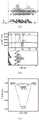
(a)~(c)分别为实施例2中碳化钛纳米棒状薄片在不同放大倍数下的高分率透射电镜图像;(a)~(c) are high-resolution transmission electron microscope images of titanium carbide nanorod-shaped flakes under different magnifications respectively in
(d)~(f)分别为对比例1中纯C3N5的扫描电镜和透射电镜图像;(d) to (f) are the scanning electron microscope and transmission electron microscope images of pureC3N5 in comparative example 1, respectively;
(g)~(i)分别为实施例2中TC/CN-15的扫描电镜和透射电镜图像;(g)~(i) are the SEM and TEM images of TC/CN-15 in Example 2 respectively;
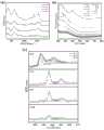
图2中:In Figure 2:
(a)为对比例1中纯C3N5、对比例2中多层堆叠的碳化钛和实施例2中TC/CN-15的X射线衍射图谱(XRD);(a) is the X-ray diffraction pattern (XRD) of pure C3 N5 in Comparative Example 1, titanium carbide stacked in multiple layers in Comparative Example 2, and TC/CN-15 in Example 2;
(b)为对比例1中纯C3N5、对比例2中多层堆叠的碳化钛和实施例2中TC/CN-15的傅里叶红外吸收光谱(FTIR);(b) is the Fourier transform infrared absorption spectrum (FTIR) of pure C3 N5 in Comparative Example 1, the multilayer stacked titanium carbide in Comparative Example 2, and TC/CN-15 in Example 2;
图3为对比例1中纯C3N5、对比例2中多层堆叠的碳化钛和实施例2中TC/CN-15的X射线光电子能谱;Fig. 3 is the X-ray photoelectron spectrum of pure C3 N5 in Comparative Example 1, titanium carbide multilayer stacked in Comparative Example 2 and TC/CN-15 in Example 2;
图4为对比例1中纯C3N5、对比例2中多层堆叠的碳化钛和实施例2中TC/CN-15的X射线光电子能谱;Fig. 4 is the X-ray photoelectron spectrum of pure C3 N5 in Comparative Example 1, the multilayer stacked titanium carbide in Comparative Example 2 and TC/CN-15 in Example 2;
其中:(a)、(b)分别为对比例1中纯C3N5与实施例2中TC/CN-15的C1s和N1s图谱及其解析;Wherein: (a), (b) are respectively the C1s and N1s spectra of pureC3N5 inComparative Example 1 and TC/CN-15 in Example 2 and their analysis;
(c)、(d)分别为对比例2中多层堆叠的碳化钛和实施例2中TC/CN-15的Ti2p和O1s图谱及其解析;(c), (d) are the Ti2p and O1s spectrum of Ti2p and O1s spectrum and analysis thereof of the titanium carbide of multilayer stacking in comparative example 2 and TC/CN-15 in
图5中:In Figure 5:
(a)为TC/CN-10、TC/CN-15、TC/CN-20、纯C3N5和多层堆叠的碳化钛的紫外-可见光-近红外(UV-vis-NIR)吸收光谱;(a) Ultraviolet-visible-near-infrared (UV-vis-NIR) absorption spectra for TC/CN-10, TC/CN-15, TC/CN-20, pureC3N5 andmultilayer stacked TiC ;
(b)为实施例2中TC/CN-15和对比例1中纯C3N5相应(αhν)1/2与hν图;(b) is the corresponding (αhν ) 1/2 and hν diagram of TC/CN-15 in Example 2 and pure C3 N5 in Comparative Example 1;
图6中:In Figure 6:
(a)为通过DFT计算的C3N5/Ti3C2O2/H2O的电荷密度差异图;(a) is the charge density difference diagram of C3 N5 /Ti3 C2 O2 /H2 O calculated by DFT;
(b)为C3N5/Ti3C2O2/H2O沿c轴对应的平面平均电荷密度差异,等值面值为
(c)为C3N5、Ti3C2O2、Ti3C2O2/C3N5界面上析氢反应的自由能图;(c) is the free energy diagram of the hydrogen evolution reaction on the interface of C3 N5 , Ti3 C2 O2 , Ti3 C2 O2 /C3 N5 ;
图7中:In Figure 7:
(a)、(b)分别为碳化钛薄片悬浮液经不同时间光照后的拉曼图谱、紫外-可见吸收光谱;(a) and (b) are the Raman spectrum and UV-visible absorption spectrum of the titanium carbide thin flake suspension after being illuminated for different times;
(c)为实施例2中TC/CN-15经不同光照时间后的X射线光电子能谱;(c) is the X-ray photoelectron spectrum of TC/CN-15 after different illumination time in
图8为实施例2中TC/CN-15经12小时光照后的高分辨率透射电镜,其中:Fig. 8 is the high-resolution transmission electron microscope of TC/CN-15 after 12 hours of illumination in
(a)为原位生成的TiO2(101)晶面;(a) TiO2 (101) crystal face generated in situ;
(b)为原位生成的石墨烯(002)晶面;(b) is a graphene (002) crystal face generated in situ;
图9为在Ti3C2O2(001)/C3N5和石墨烯(002)/C3N5模型上优化后的H2O分子吸附的电荷差异分布。Fig. 9 shows the charge difference distribution of optimized H2 O molecular adsorption on Ti3 C2 O2 (001)/C3 N5 and graphene (002)/C3 N5 models.
具体实施方式Detailed ways
下面将结合实施例对本发明作进一步说明:The present invention will be further described below in conjunction with embodiment:
实施例中采用的原料:The raw material that adopts in the embodiment:
Ti3AlC2(200目,纯度>98%)购于福斯曼科技(北京)有限公司(中国北京),3-氨基-1,2,4-三氮唑(纯度>96%)购于麦克林生化科技有限公司(中国上海),氢氟酸(40wt.%)和盐酸(36-38wt.%)购自国药集团化学试剂有限公司(中国上海)。所有其他化学品均为分析级。实验所用水位超纯水(电阻≥18.2MΩ·cm-1)。Ti3 AlC2 (200 mesh, purity>98%) was purchased from Forsman Technology (Beijing) Co., Ltd. (Beijing, China), and 3-amino-1,2,4-triazole (purity>96%) was purchased from McLean Biochemical Technology Co., Ltd. (Shanghai, China), hydrofluoric acid (40wt.%) and hydrochloric acid (36-38wt.%) were purchased from Sinopharm Chemical Reagent Co., Ltd. (Shanghai, China). All other chemicals were of analytical grade. The water level used in the experiment was ultrapure water (resistance ≥ 18.2MΩ·cm-1 ).
实施例1~3Examples 1-3
将1.0g Ti3AlC2粉末缓慢加入40mL浓HF溶液(40wt%)中,并保持连续搅拌24h,得到多层堆叠的碳化钛(Ti3C2Tx)。将所得多层碳化钛用超纯水洗涤数次,直至黑色悬浮液的pH值达到6-7;将调解pH后的多层碳化钛重新分散在60mL的超纯水中,并持续超声处理3小时,得到含有碳化钛纳米棒状薄片的深绿色上清液,记为碳化钛薄片悬浮液。1.0 g of Ti3 AlC2 powder was slowly added into 40 mL of concentrated HF solution (40 wt%) and kept stirring continuously for 24 h to obtain multilayer stacked titanium carbide (Ti3 C2 Tx ). Wash the obtained multilayer titanium carbide with ultrapure water several times until the pH value of the black suspension reaches 6-7; redisperse the multilayer titanium carbide after adjusting the pH in 60mL of ultrapure water, and continue ultrasonic treatment for 3 Hours, a dark green supernatant containing titanium carbide nanorod flakes was obtained, which was referred to as the titanium carbide flake suspension.
将2.0g 3-氨基-1,2,4-三氮唑放入50mL有盖刚玉坩埚中,在500℃、5℃·min-1的升温速率下煅烧3h,之后,收集残留的棕色C3N5并研磨成细粉。将200mgC3N5粉末分散于50mL、浓度为1.2mol/L的盐酸中进行质子化反应,搅拌4小时,离心分离并洗涤数次,再次重新分散在15mL超纯水中,得质子化C3N5悬浮液。Put 2.0g of 3-amino-1,2,4-triazole into a 50mL corundum crucible with a lid, and calcinate at 500°C for 3h at a heating rate of 5°C·min-1 , after that, collect the residual brown C3 N5 and ground to a fine powder. Disperse 200 mg of C3 N5 powder in 50 mL of hydrochloric acid with a concentration of 1.2 mol/L for protonation reaction, stir for 4 hours, centrifuge and wash several times, and re-disperse in 15 mL of ultrapure water to obtain protonated C3N5 suspension.
然后,按照表1所示,将不同体积的碳化钛薄片悬浮液(即10、15和20mL)分别逐滴缓慢加入上述质子化C3N5悬浮液中,搅拌2.5小时。最后,离心分离Ti3C2Tx/C3N5复合材料,然后在真空烘箱中干燥,直至去除所有水分,得到实施例1~3对应的碳化钛/氮化碳复合光催化剂样品,分别记为TC/CN-X(X=10、15和20)。Then, as shown in Table 1, different volumes of titanium carbide flake suspensions (ie, 10, 15 and 20 mL) were slowly added dropwise to the above-mentioned protonated C3 N5 suspension, and stirred for 2.5 hours. Finally, centrifuge the Ti3 C2 Tx /C3 N5 composite material, and then dry it in a vacuum oven until all moisture is removed to obtain the titanium carbide/carbon nitride composite photocatalyst samples corresponding to Examples 1-3, respectively Recorded as TC/CN-X (X = 10, 15 and 20).
表1实施例1~3中质子化氮化碳悬浮液和碳化钛薄片悬浮液的添加量The amount of protonated carbon nitride suspension and titanium carbide flake suspension in Table 1 Examples 1 to 3

对比例1Comparative example 1
将2.0g 3-氨基-1,2,4-三氮唑放入50mL有盖刚玉坩埚中,在500℃、5℃·min-1的升温速率下煅烧3h,之后,收集残留的棕色样品并研磨成细粉,得到纯C3N5。Put 2.0g of 3-amino-1,2,4-triazole into a 50mL covered corundum crucible, and calcined at 500°C for 3h at a heating rate of 5°C·min-1 , after which the residual brown sample was collected and Grind into a fine powder to obtain pure C3 N5 .
对比例2Comparative example 2
将1.0g Ti3AlC2粉末缓慢加入40mL浓HF溶液(40wt%)中,并保持连续搅拌24h。将所得多层Ti3C2用超纯水洗涤数次,直至黑色悬浮液的pH值达到6-7,然后在真空烘箱中干燥,直至去除所有水分,得到多层堆叠的碳化钛。1.0 g of Ti3 AlC2 powder was slowly added into 40 mL of concentrated HF solution (40 wt%) and kept stirring continuously for 24 h. The obtained multilayerTi3C2 was washed several times with ultrapure water until the pH of the black suspension reached 6–7, and then dried ina vacuum oven until all moisture was removed to obtain multilayer stacked TiC.
催化剂的表征1
碳化钛纳米棒状薄片和质子化后的C3N5(质子化C3N5)的zeta电位分别为-16.2mV和11.0mV,因而两者混合后可因强烈的静电吸附形成稳定的复合物。该复合物(实施例2)的形貌结构由高分辨率透射电镜及扫描电镜进行观察,如图1所示。经过强烈超声处理后,多层堆叠的碳化钛剥离并形成碳化钛纳米棒状薄片(如图1中(a)~(c)所示)。对比例1中制得的纯C3N5具有块状结构(如图1中(d)~(f)所示)。图1中(g)~(i)显示碳化钛纳米棒状薄片和质子化C3N5发生明显的复合,纳米棒状碳化钛薄片被强烈吸引到C3N5表面。The zeta potentials of titanium carbide nanorod flakes and protonated C3 N5 (protonated C3 N5 ) are -16.2mV and 11.0mV respectively, so they can form a stable complex due to strong electrostatic adsorption after mixing . The morphology and structure of the complex (Example 2) were observed by high-resolution transmission electron microscope and scanning electron microscope, as shown in Figure 1. After intense ultrasonic treatment, the multilayer stacked TiC peeled off and formed TiC nanorod flakes (as shown in (a)-(c) in Figure 1). The pure C3 N5 prepared in Comparative Example 1 has a block structure (as shown in (d)-(f) in FIG. 1 ). (g)-(i) in Figure 1 show that titanium carbide nanorod-shaped flakes and protonated C3 N5 are obviously recombined, and nanorod-shaped titanium carbide flakes are strongly attracted to the surface of C3 N5 .
在制备复合光催化剂的过程中C3N5需要进行质子化处理,因此,C3N5层间距由于静电斥力而增大,如表2所示,复合之后经N2等温吸附模型测得的比表面积和孔容明显增大,从而暴露出更多的活性位点,并促进分子的扩散/迁移和H2解吸。In the process of preparing the composite photocatalyst, C3 N5 needs to be protonated. Therefore, the interlayer distance of C3 N5 increases due to electrostatic repulsion, as shown in Table 2. After compounding, the N2 isothermal adsorption model measures The specific surface area and pore volume are significantly increased, thereby exposing more active sites and facilitating the diffusion/migration of molecules andH2 desorption.
表2实施例2中TC/CN-15与对比例1中纯C3N5的比表面积和孔容量对比Table 2 Comparison of specific surface area and pore volume between TC/CN-15 in Example 2 and pure C3 N5 in Comparative Example 1

催化剂的表征2
实施例2中制得的TC/CN-15、对比例1中制得的纯C3N5和对比例2中制得的多层堆叠的碳化钛的化学结构由XRD、FTIR和XPS进行表征。其中,XRD、FTIR表征结果如图2所示,纯C3N5在图2中显示为C3N5,多层堆叠的碳化钛在图2中显示为Ti3C2。如图2中(a)所示,TC/CN-15中保留了较为完整的C3N5特征衍射峰,27.5°处对应于C3N5(002)晶面,由共轭芳族CN片的层间堆叠引起。位于13.0°处的峰与C3N5(100)晶面有关。由于TC/CN-15中碳化钛层状结构被破坏,且含量较低,因此未发现明显的对应碳化钛的衍射峰。在图2中(b)的傅里叶红外谱图中,TC/CN-15和纯C3N5同样显示出相似的特征峰。此外,在TC/CN-15中,3435cm-1处的信号峰属于碳化钛边缘的羟基(–OH),1103cm-1处的峰和1635cm-1处的峰可以分别归因于C–F和C=O键的振动,证明质子化C3N5和碳化钛纳米棒状薄片发生了复合。The chemical structures of the TC/CN-15 prepared in Example 2, the pure C3 N5 prepared in Comparative Example 1 and the multilayer stacked titanium carbide prepared in Comparative Example 2 were characterized by XRD, FTIR and XPS . Among them, XRD and FTIR characterization results are shown in Figure 2, pure C3 N5 is shown as C3 N5 in Figure 2, and multilayer stacked titanium carbide is shown as Ti3 C2 in Figure 2. As shown in (a) of Figure 2, the relatively complete C3 N5 characteristic diffraction peaks are retained in TC/CN-15, and the 27.5° corresponds to the C3 N5 (002) crystal plane. Interlayer stacking of slices is caused. The peak at 13.0° is associated with the C3 N5 (100) crystal plane. Since the layered structure of titanium carbide in TC/CN-15 was destroyed and the content was low, no obvious diffraction peak corresponding to titanium carbide was found. In the FTIR spectrum of Fig. 2(b), TC/CN-15 and pure C3 N5 also show similar characteristic peaks. In addition, in TC/CN-15, the signal peak at 3435cm-1 belongs to the hydroxyl group (–OH) on the edge of titanium carbide, and the peaks at 1103cm-1 and 1635cm-1 can be attributed to C–F and The vibration of the C=O bond proves that protonated C3 N5 and titanium carbide nanorod flakes are recombined.
利用X射线光电子能谱(XPS)光谱对TC/CN-15、纯C3N5和多层堆叠的碳化钛的表面化学结构进行了深入研究,结果如图3和图4所示,纯C3N5在图3、图4中显示为C3N5;多层堆叠的碳化钛在图3、图4中显示为Ti3C2。如图3和4所示,TC/CN-15中同时存在C、N、Ti和O四种元素。其中C1s光谱(图4中(a))可以在281.2、284.8和288.1eV处解卷积为三个峰,对应于TC/CN-15中的C–Ti键、sp2杂化C、C3N5中的三嗪C。在N1s光谱(图4中(b))中位于398.7、400.0、401.0和404.6eV的拟合峰分别为TC/CN-15中的C=N–C、N–(C)3、C–N–H边缘氨基、以及π-π*激发的电荷效应;与C3N5相比,N1s光谱中TC/CN-15的峰位置呈现正位移,表明电子从电子供体C3N5流向电子受体碳化钛助催化剂(碳化钛纳米棒状薄片)。从Ti2p光谱中(图4中(c))可以看出,多层堆叠的碳化钛中没有观察到明显的四价钛峰,而在TC/CN-15样品中,TixOy峰被TiO2峰取代(458.2和463.9eV),这可能是由于边缘部位的弱Ti–O键与羟基之间发生化学氧化反应。O1s光谱(图4中(d))中529.3和529.6eV处的两个峰可归于Ti-O键和吸附的O,而531.6和532.3eV处的峰分别为吸附的羟基Ti–OH和C-OH。XPS分析证明了质子化C3N5和碳化钛纳米棒状薄片界面之间的强电子相互作用。The surface chemical structures of TC/CN-15, pure C3 N5 and multilayer stacked TiC were studied in depth by X-ray photoelectron spectroscopy (XPS), and the results are shown in Fig. 3 and Fig. 4. Pure C3 N5 is shown as C3 N5 in Figure 3 and Figure 4; multilayer stacked titanium carbide is shown as Ti3 C2 in Figure 3 and Figure 4 . As shown in Figures 3 and 4, four elements, C, N, Ti and O, exist simultaneously in TC/CN-15. Among them, the C1s spectrum ((a) in Fig. 4) can be deconvoluted into three peaks at 281.2, 284.8 and 288.1 eV, corresponding to the C–Ti bond, sp2 hybridized C, C3 Triazine C in N5 . The fitting peaks at 398.7, 400.0, 401.0 and 404.6eV in the N1s spectrum ((b) in Figure 4) are C=N–C, N–(C)3, C–N in TC/CN-15, respectively – H-edge amino groups, and the charge effect of π-π* excitation; compared with C3 N5 , the peak position of TC/CN-15 in the N1s spectrum shows a positive shift, indicating electron flow from electron donor C3 N5 to electron Acceptor titanium carbide cocatalyst (titanium carbide nanorod flakes). From the Ti2p spectrum (Fig. 4(c)), it can be seen that no obvious tetravalent titanium peak is observed in the multilayer stacked TiC, while in the TC/CN-15 sample, the Tix Oy peak is replaced by the TiO2 peak substitutions (458.2 and 463.9 eV), which may be due to the chemical oxidation reaction between the weak Ti–O bond at the edge and the hydroxyl group. The two peaks at 529.3 and 529.6 eV in the O1s spectrum (Fig. 4(d)) can be attributed to the Ti-O bond and the adsorbed O, while the peaks at 531.6 and 532.3 eV are the adsorbed hydroxyl Ti–OH and C- Oh. XPS analysis demonstrates strong electronicinteractions between protonatedC3N5 and titanium carbide nanorod-like flake interfaces.
催化剂的表征3
催化剂的光学性能利用紫外-可见光-近红外(UV-vis-NIR)固态吸收光谱。如图5中(a)所示,实施例1~3中制得的TC/CN-10、TC/CN-15、TC/CN-20均表现出从紫外、可见光到近红外光的光响应范围,而对比例1制得的纯C3N5(在图中显示为C3N5)在近红外光区域表现出较差的光吸收。使用Kubelka-Munk公式进一步确定了TC/CN-15和纯C3N5(在图中显示为C3N5)的带隙Eg(图5中(b))。纯C3N5的带隙为2.05eV,而TC/CN-15的带隙计算为1.85eV,说明质子化C3N5与碳化钛纳米棒状薄片复合后带隙变窄。半导体的能带结构,尤其是它们的能带位置(即导带(CB)边缘和价带(VB)边缘),对光催化HER性能有很大影响。结合分析莫特-肖特基图、XPS价带谱分别计算出TC/CN-15和纯C3N5的导带(CB)位置分别为-1.19和-0.60(Vvs.NHE)。从表3中看出,CB电位的这种显著负移和复合碳化钛助催化剂的带隙变窄,提高了催化剂的还原能力,从而在很大程度上促进了H2的析出速率。The optical properties of the catalysts utilize ultraviolet-visible-near-infrared (UV-vis-NIR) solid-state absorption spectroscopy. As shown in Figure 5 (a), TC/CN-10, TC/CN-15, and TC/CN-20 prepared in Examples 1 to 3 all exhibit photoresponses from ultraviolet, visible light to near-infrared light range, while the pure C3 N5 prepared in Comparative Example 1 (shown as C3 N5 in the figure) exhibited poor light absorption in the near-infrared light region. The band gap Eg of TC/CN-15 and pure C3 N5 (shown as C3 N5 in the figure) was further determined using the Kubelka-Munk formula (Fig. 5(b)). The bandgap of pure C3 N5 is 2.05eV, while that of TC/CN-15 is calculated to be 1.85eV, indicating that the bandgap becomes narrower after protonated C3 N5 is recombined with titanium carbide nanorod flakes. The energy band structures of semiconductors, especially their energy band positions (i.e. conduction band (CB) edge and valence band (VB) edge), have a great influence on the photocatalytic HER performance. The conduction band (CB) positions of TC/CN-15 and pure C3 N5 were calculated to be -1.19 and -0.60 (Vvs.NHE) by combining analysis of Mott-Schottky plot and XPS valence band spectrum, respectively. It can be seen from Table 3 that this significant negative shift of the CB potential and the narrowing of the bandgap of the composite titanium carbide cocatalysts enhance the reducing ability of the catalysts, thereby promoting theH evolution rate to a great extent.
表3实施例2中TC/CN-15和对比例1中纯C3N5的带隙及能带位置The band gap and energy band position of TC/CN-15 in the


表4列出了通过分析实施例2中制得的TC/CN-15和对比例1中制得的纯C3N5的时间分辨光致发光(TRPL)衰减曲线得到的动态电荷数据。相比于纯C3N5,TC/CN-15的平均寿命(τaverage)从5.35ns缩短到3.46ns;衰减τ平均值揭示了非辐射衰减跃迁的出现,表明碳化钛助催化剂和质子化C3N5界面之间的发生有效激子解离,从而为TC/CN-15异质界面中的空间电荷分离提供了强有力的证据。Table 4 lists the dynamic charge data obtained by analyzing the time-resolved photoluminescence (TRPL) decay curves of TC/CN-15 prepared in Example 2 and pure C3 N5 prepared in Comparative Example 1. Compared with pure C3 N5 , the average lifetime (τaverage ) of TC/CN-15 is shortened from 5.35 ns to 3.46 ns; the decay τ average reveals the appearance of non-radiative decay transitions, indicating the titanium carbide co-catalyst and protonation Effective exciton dissociation occurs betweentheC3N5 interface, thus providing strong evidence for space charge separation in the TC/CN-15 heterointerface.
表4实施例2中TC/CN-15和对比例1中纯C3N5中量子平均寿命和及其百分比贡献TC/CN-15 in the

催化剂性能测试Catalyst performance test
将30mg制备好的催化剂样品加入含有40mL三乙醇胺溶液(10wt%)的烧瓶中,然后超声处理30min。之后,用高纯氮气(N2)鼓泡以除去反应器中的残留空气。在光催化析氢测试中,光源(波长范围从300到1100nm)由300W氙灯提供。氙灯与反应器(烧瓶)之间的照射距离设为4cm。反应器在磁力搅拌下确保催化剂样品均匀分布在悬浮液中,并采用循环冷却水系统将反应器的温度保持在298K(±0.2K)。气体体积由配备热导检测器(TCD)的气相色谱仪(GC-9200)进行测定监测。其中,催化剂样品分别为TC/CN-10、TC/CN-15、TC/CN-20、纯C3N5和多层堆叠的碳化钛。30 mg of the prepared catalyst sample was added into a flask containing 40 mL of triethanolamine solution (10 wt %), and then sonicated for 30 min. Afterwards, high-purity nitrogen (N2 ) was sparged to remove residual air in the reactor. In the photocatalytic hydrogen evolution test, the light source (wavelength range from 300 to 1100 nm) was provided by a 300W xenon lamp. The irradiation distance between the xenon lamp and the reactor (flask) was set to 4 cm. The reactor was stirred under magnetic force to ensure that the catalyst sample was evenly distributed in the suspension, and a circulating cooling water system was used to keep the temperature of the reactor at 298K (±0.2K). The gas volume was measured and monitored by a gas chromatograph (GC-9200) equipped with a thermal conductivity detector (TCD). Among them, the catalyst samples are TC/CN-10, TC/CN-15, TC/CN-20, pure C3 N5 and multilayer stacked titanium carbide.
密度泛函计算(DFT)从理论角度对催化剂性能进行评价。计算使用Vienna Ab-initio Simulation Package(VASP)代码进行,采用由自旋极化广义梯度近似(GGA)和Perdew-Burke-Ernzerhof(PBE)函数进行,以及能量截止为520eV的全电子平面波基组和投影仪增强波(PAW)方法进行计算。采用一个(3×3×1)Monkhorst-Pack k点网格对布里渊区积分进行采样,优化中采用共轭梯度算法。每个原子上的收敛阈值设置为1×10⁻⁴eV的总能量和

性能测试例1Performance test example 1
采用光照实验评估了TC/CN-10、TC/CN-15、TC/CN-20、纯C3N5和多层堆叠的碳化钛的氢气产生速率,结果如表5所示。从表5中可以看出,与碳化钛纳米棒状薄片的复合极大地提高了C3N5的光催化产氢活性,结合表征结果可以认为,其原因在于碳化钛纳米棒状薄片与质子化C3N5复合后光催化剂比表面积和孔容的增大,能带结构的调整以及空间电荷的有效分离。其中,TC/CN-15表现出最高的H2生成速率,为506.57μmol·g-1·h-1,几乎是纯C3N5生成速率的4倍。然而,进一步的碳化钛纳米棒状薄片的增加反而会导致H2生成率的下降。The hydrogen generation rates of TC/CN-10, TC/CN-15, TC/CN-20, pureC3N5 and multilayer stacked TiC were evaluated by illumination experiments, and the results are shown in Table5 . It can be seen from Table 5 that the combination with titanium carbide nanorod flakes greatly improves the photocatalytic hydrogen production activity of C3 N5 , combined with the characterization results, it can be considered that the reason is that titanium carbide nanorod flakes interact with protonated C3 The increase of specific surface area and pore volume of the photocatalyst afterN5 recombination, the adjustment of energy band structure and the effective separation of space charges. Among them, TC/CN-15 exhibited the highest H2 generation rate of 506.57μmol·g-1 ·h-1 , almost four times that of pure C3 N5 . However, the further increase of TiC nanorod flakes would instead lead to a decrease in theH2 generation rate.
表5不同催化剂催化产气的速率Table 5 Catalytic gas production rate of different catalysts


性能测试例2Performance test example 2
根据表征结果,TC/CN-15中Ti被部分氧化,因此在进行DFT计算时,选择具有O端的碳化钛单层(记为Ti3C2O2)作为计算模型,将单层Ti3C2O2(001)堆叠在C3N5(001)片的顶部以构建Ti3C2O2/C3N5异质结构。从图6中(a)和(b)可以看出,电荷密度差异和平面平均电荷密度差异结果表明,Ti3C2O2中末端的O原子是光催化产氢的有效活性位点,O原子与吸附在表面的水分子之间发生了定向电荷迁移。Bader电荷分析表明,大约0.14个电子被注入到一个水分子中。因此,TC/CN-15复合催化剂中,C3N5中的电子由N向Ti3C2O2迁移,并汇聚在末端O原子周围,从而有利于水的还原。同时,从图6中(c)可以看出,Ti3C2O2/C3N5异质结构在Ti3C2O2/C3N5、Ti3C2O2和C3N5中表现出最低的自由能垒,为-0.168eV(H*吸附在Ti3C2O2中的末端O原子上),从而证明TC/CN-15复合催化剂对光解水产氢的能力最高。According to the characterization results, Ti in TC/CN-15 is partially oxidized, so when performing DFT calculations, a single layer of titanium carbide (denoted as Ti3 C2 O2 ) with an O terminal is selected as the calculation model, and the single layer of Ti3 C2 O2 (001) is stacked on top of the C3 N5 (001) sheet to construct the Ti3 C2 O2 /C3 N5 heterostructure. It can be seen from (a) and (b) in Figure 6 that the results of the difference in charge density and the difference in plane average charge density show that the terminal O atom in Ti3 C2 O2 is an effective active site for photocatalytic hydrogen production, and O A directional charge transfer occurs between the atoms and the water molecules adsorbed on the surface. Bader charge analysis shows that about 0.14 electrons are injected into a water molecule. Therefore, in the TC/CN-15 composite catalyst, the electrons in C3 N5 migrate from N to Ti3 C2 O2 and gather around the terminal O atoms, which is beneficial to the reduction of water. At the same time, it can be seen from (c) in Figure 6 that the Ti3 C2 O2 /C3 N5 heterostructure is in the Ti3 C2 O2 /C3 N5 , Ti3 C2 O2 and C3 N5 exhibits the lowest free energy barrier of -0.168eV (H* is adsorbed on the terminal O atoms inTi3C2O2 ), thus proving that theTC /CN-15composite catalyst has the highest ability for photolysis of water to generate hydrogen .
性能测试例3Performance test example 3
为评价实施例2中制得的复合催化剂的催化稳定性能,对TC/CN-15进行了循环的光催化产氢实验,测得产气速率如表6所示。经4小时的连续光照产氢实验后,复合光催化剂经过离心、分离后,再次分散于10wt%的三乙醇胺溶液中,进行第二次光催化产氢实验,连续进行6次循环。由表6可知,在第2~4次循环使用中氢气产率有明显升高,之后再缓慢下降。由于C3N5结构比较稳定,因此碳化钛助催化剂的化学成分变化可能是催化活性升高的原因。为此,对实施例2中碳化钛薄片悬浮液的拉曼光谱进行了测定,结果如图7中(a)所示。在图7中(a)中观察到属于D和G带的两个典型峰,其中D带表明无序,而G带与石墨碳性质有关。G带的强度随着光照时间的增加而增加,这表明石墨相碳物种的形成。图7中(b)中的碳化钛薄片悬浮液的紫外-可见光吸收光谱反映了碳化钛薄片悬浮液在光照后光捕获能力逐渐增强,连续照射超过9小时后在235nm处出现强峰,可能为石墨相碳的增多导致的π~π*跃迁。In order to evaluate the catalytic stability of the composite catalyst prepared in Example 2, a cyclic photocatalytic hydrogen production experiment was carried out on TC/CN-15, and the measured gas production rate is shown in Table 6. After 4 hours of continuous photocatalytic hydrogen production experiment, the composite photocatalyst was centrifuged and separated, and then dispersed in 10wt% triethanolamine solution for the second photocatalytic hydrogen production experiment, with 6 consecutive cycles. It can be seen from Table 6 that the hydrogen production rate increased significantly in the 2nd to 4th cycle, and then decreased slowly. Due to the relatively stable structure of C3 N5 , the change in the chemical composition of the titanium carbide co-catalyst may be the reason for the increase in catalytic activity. For this reason, the Raman spectrum of the titanium carbide flake suspension in Example 2 was measured, and the results are shown in (a) of FIG. 7 . Two typical peaks belonging to the D and G bands are observed in Fig. 7(a), where the D band indicates disorder and the G band is related to the graphitic carbon properties. The intensity of the G-band increases with increasing illumination time, which indicates the formation of graphitic carbon species. The ultraviolet-visible light absorption spectrum of the titanium carbide flake suspension in (b) in Figure 7 reflects that the light-harvesting ability of the titanium carbide flake suspension gradually increases after irradiation, and a strong peak appears at 235 nm after continuous irradiation for more than 9 hours, which may be The π~π* transition caused by the increase of graphitic carbon.
表6实施例2中TC/CN-15循环使用过程中的氢气产率Hydrogen production rate in TC/CN-15 recycling process in the

通过对不同光照时间后的TC/CN-15进行XPS分析发现,如图7中(c)所示,光照射3小时后,TC/CN-15中的Ti–C和Ti–X峰消失,而Ti–O(TiO2)峰的强度显著增加。Ti–C、Ti–X峰的消失、新出现的Ti-O信号和增强的D带强度源于在Ti–C键边缘位置发生的氧化反应,二氧化钛和石墨相碳原位生成,并形成石墨烯(C-C)量子点和二氧化钛(TiO2)量子点。随着光照时间的延长,四价钛的峰值强度进一步降低,这可能是由于表面电荷改性引起的二氧化钛纳米颗粒的脱离。对经过12小时光照后的TC/CN-15进行高分辨率透射电镜观察,结果如图8所示,在图8中(a)中,复合光催化剂表面出现间距为0.249nm的晶格条纹,为TiO2(101)晶面,同时在图8中(b)中,观察到了间距为0.368nm的晶格条纹,为石墨烯(002)晶面。Through XPS analysis of TC/CN-15 after different illumination times, it was found that, as shown in (c) of Figure 7, after 3 hours of light irradiation, the Ti–C and Ti–X peaks in TC/CN-15 disappeared, However, the intensity of the Ti–O(TiO2 ) peak increases significantly. The disappearance of Ti–C and Ti–X peaks, the emerging Ti–O signal, and the enhanced D band intensity originate from the oxidation reaction at the edge of the Ti–C bond, in situ formation of TiO and graphitic carbon, and the formation of graphite ene (CC) quantum dots and titanium dioxide (TiO2 ) quantum dots. The peak intensity of tetravalent titanium further decreased with the prolongation of the illumination time, which may be due to the detachment of titanium dioxide nanoparticles caused by surface charge modification. After 12 hours of light exposure, TC/CN-15 was observed by high-resolution transmission electron microscopy, and the results are shown in Figure 8. In Figure 8 (a), lattice fringes with a spacing of 0.249 nm appear on the surface of the composite photocatalyst. It is a TiO2 (101) crystal plane, and at the same time in Figure 8 (b), lattice fringes with a pitch of 0.368nm are observed, which is a graphene (002) crystal plane.
性能测试例4Performance test example 4
为证实由于碳化钛末端的氧化提高了产氢速率,通过DFT计算了H2O分子在Ti3C2O2(001)/C3N5和石墨烯(002)/C3N5表面上的吸附能,结果如图9所示。由图9可以看出,H2O在石墨烯(002)/C3N5上的吸附能(Eads)为-1.997eV,比在Ti3C2O2(001)/C3N5(-0.518eV)上更负,表明H2O分子更易吸附在石墨烯(002)/C3N5界面上,因此促进了H2O的催化还原。Bader分析表明,Ti3C2O2和石墨烯分别向H2O注入了0.14和0.09个电子。因此,原位生成的石墨相碳(石墨烯(C-C)量子点),可以通过增强对水的吸附显著提升产氢速率。To confirm the enhanced hydrogen production rate due to the oxidation of TiC ends, the H2 O molecules on Ti3 C2 O2 (001)/C3 N5 and graphene (002)/C3 N5 surfaces were calculated by DFT The adsorption energy is shown in Figure 9. It can be seen from Figure 9 that the adsorption energy (Eads) of H2 O on graphene (002)/C3 N5 is -1.997eV, which is higher than that on Ti3 C2 O2 (001)/C3 N5 ( -0.518eV), indicating that H2 O molecules are more easily adsorbed on the graphene (002)/C3 N5 interface, thus promoting the catalytic reduction of H2 O. Baderanalysis showed thatTi3C2O2 andgraphene injected 0.14 and 0.09 electrons intoH2O , respectively. Therefore, the in situ generation of graphitic carbon (graphene (CC) quantum dots) can significantly enhance the hydrogen production rate by enhancing the adsorption of water.
Claims (9)
Priority Applications (1)
| Application Number | Priority Date | Filing Date | Title |
|---|---|---|---|
| CN202111202849.3ACN113751049B (en) | 2021-10-15 | 2021-10-15 | Preparation method, product and application of titanium carbide/carbon nitride composite photocatalyst |
Applications Claiming Priority (1)
| Application Number | Priority Date | Filing Date | Title |
|---|---|---|---|
| CN202111202849.3ACN113751049B (en) | 2021-10-15 | 2021-10-15 | Preparation method, product and application of titanium carbide/carbon nitride composite photocatalyst |
Publications (2)
| Publication Number | Publication Date |
|---|---|
| CN113751049A CN113751049A (en) | 2021-12-07 |
| CN113751049Btrue CN113751049B (en) | 2023-03-28 |
Family
ID=78799582
Family Applications (1)
| Application Number | Title | Priority Date | Filing Date |
|---|---|---|---|
| CN202111202849.3AActiveCN113751049B (en) | 2021-10-15 | 2021-10-15 | Preparation method, product and application of titanium carbide/carbon nitride composite photocatalyst |
Country Status (1)
| Country | Link |
|---|---|
| CN (1) | CN113751049B (en) |
Families Citing this family (4)
| Publication number | Priority date | Publication date | Assignee | Title |
|---|---|---|---|---|
| CN114917947B (en)* | 2022-05-18 | 2023-10-27 | 成都理工大学 | A C3N5/CLDHs composite photocatalytic material and its preparation method |
| CN116196959B (en)* | 2023-01-15 | 2024-11-01 | 湖南工商大学 | Hydroxyl functional titanium carbide loaded carbon nitride photocatalyst and preparation and application thereof |
| CN116713016B (en)* | 2023-05-12 | 2024-06-14 | 华南师范大学 | Preparation method of surface co-modified graphite phase nitrogen-rich carbon nitride and application of surface co-modified graphite phase nitrogen-rich carbon nitride in photocatalytic hydrogen production |
| CN117324018A (en)* | 2023-09-28 | 2024-01-02 | 沈阳工程学院 | High-crystallinity CN homojunction photocatalyst and preparation method and application thereof |
Family Cites Families (5)
| Publication number | Priority date | Publication date | Assignee | Title |
|---|---|---|---|---|
| CN110013869B (en)* | 2019-02-19 | 2022-03-11 | 武汉理工大学 | A kind of carbon nitride nanosheet supported titanium carbide quantum dots and preparation method and application thereof |
| CN110180577B (en)* | 2019-06-18 | 2020-07-24 | 中国石油大学(北京) | A kind of photocatalyst for photocatalytic water splitting, preparation method and application thereof |
| CN111215115A (en)* | 2020-02-05 | 2020-06-02 | 中南民族大学 | Preparation of two-dimensional titanium carbide/two-dimensional graphite phase carbon nitride nanosheet heterojunction and application of heterojunction in photocatalytic reduction of CO2 |
| CN111573637A (en)* | 2020-05-21 | 2020-08-25 | 常州工学院 | Nitrogen-rich carbon nitride nanosheet and preparation method thereof |
| CN112495421B (en)* | 2020-12-09 | 2023-11-24 | 北华大学 | A method for preparing a nitrogen-doped carbon quantum dot modified nitrogen-rich graphite carbon nitride photocatalyst |
- 2021
- 2021-10-15CNCN202111202849.3Apatent/CN113751049B/enactiveActive
Also Published As
| Publication number | Publication date |
|---|---|
| CN113751049A (en) | 2021-12-07 |
Similar Documents
| Publication | Publication Date | Title |
|---|---|---|
| Cheng et al. | Boosting the photocatalytic activity of CdLa2S4 for hydrogen production using Ti3C2 MXene as a co-catalyst | |
| CN113751049B (en) | Preparation method, product and application of titanium carbide/carbon nitride composite photocatalyst | |
| You et al. | State-of-the-art recent progress in MXene-based photocatalysts: a comprehensive review | |
| Chen et al. | Two-dimensional heterojunction photocatalysts constructed by graphite-like C3N4 and Bi2WO6 nanosheets: enhanced photocatalytic activities for water purification | |
| Han et al. | Significant enhancement of visible-light-driven hydrogen evolution by structure regulation of carbon nitrides | |
| Yu et al. | In situ self-transformation synthesis of g-C3N4-modified CdS heterostructure with enhanced photocatalytic activity | |
| Bai et al. | Integrating MoS2 on sulfur-doped porous g-C3N4 iostype heterojunction hybrids enhances visible-light photocatalytic performance | |
| Wang et al. | One-step calcination method for synthesis of mesoporous gC 3 N 4/NiTiO 3 heterostructure photocatalyst with improved visible light photoactivity | |
| Liu et al. | Au–Cu nanoalloy/TiO2/MoS2 ternary hybrid with enhanced photocatalytic hydrogen production | |
| Xu et al. | Synthesis and behaviors of g-C3N4 coupled with LaxCo3-xO4 nanocomposite for improved photocatalytic activeity and stability under visible light | |
| Pu et al. | Self-assembly of a gC 3 N 4-based 3D aerogel induced by N-modified carbon dots for enhanced photocatalytic hydrogen production | |
| CN106669759A (en) | Phosphor sulfur co-doped graphite phase carbon nitride photo-catalyst, preparation method and application thereof | |
| CN106111174A (en) | G C3N4/ kaolinite composite photo-catalyst and preparation method thereof | |
| CN113209998B (en) | Graphite-phase carbon nitride composite photocatalyst and preparation method thereof | |
| CN113578297B (en) | Oxygen-terminated monolayer titanium carbide composite titanium dioxide photocatalyst and preparation method thereof | |
| Wang et al. | When MoS 2 meets TiO 2: facile synthesis strategies, hybrid nanostructures, synergistic properties, and photocatalytic applications | |
| CN108380233A (en) | Phosphorus doping carbonitride/carbonitride homotype heterojunction photocatalyst and its preparation method and application | |
| CN112354553B (en) | A kind of preparation method of g-C3N4 base p-n homojunction photocatalyst and the preparation method of hydrogen | |
| Dong et al. | Facile one-pot synthesis of Mg-doped gC 3 N 4 for photocatalytic reduction of CO 2 | |
| CN109012731A (en) | Sea urchin shape CoZnAl-LDH/RGO/g-C3N4Z-type hetero-junctions and its preparation method and application | |
| Wang et al. | Facile synthesis of CoO nanorod/C3N4 heterostructure photocatalyst for an enhanced pure water splitting activity | |
| Zhao et al. | Synergistic carbon defect modulation in porous carbon nitride nanotubes for efficient photocatalytic hydrogen evolution | |
| CN108295872A (en) | A kind of hydro-thermal method preparation Bi2S3/1T@2H-MoS2Method | |
| Huang et al. | Recent progress on the photocatalytic hydrogen evolution reaction over a metal sulfide cocatalyst-mediated carbon nitride system | |
| Bai et al. | Rapid thermal surface engineering of g-C3N4 for efficient hydrogen evolution |
Legal Events
| Date | Code | Title | Description |
|---|---|---|---|
| PB01 | Publication | ||
| PB01 | Publication | ||
| SE01 | Entry into force of request for substantive examination | ||
| SE01 | Entry into force of request for substantive examination | ||
| GR01 | Patent grant | ||
| GR01 | Patent grant | ||
| TR01 | Transfer of patent right | ||
| TR01 | Transfer of patent right | Effective date of registration:20240524 Address after:315100, Qian 1, Yinzhou District, Ningbo, Zhejiang, Hunan Road Patentee after:Zhejiang University of science and engineering Ningbo Country or region after:China Patentee after:Zhejiang University Ningbo five in one Campus Education Development Center Address before:315100, Qian 1, Yinzhou District, Ningbo, Zhejiang, Hunan Road Patentee before:Zhejiang University of science and engineering Ningbo Country or region before:China |