CN113746066B - Current converter overcurrent protection method and circuit and current converter controller - Google Patents
Current converter overcurrent protection method and circuit and current converter controllerDownload PDFInfo
- Publication number
- CN113746066B CN113746066BCN202010476926.3ACN202010476926ACN113746066BCN 113746066 BCN113746066 BCN 113746066BCN 202010476926 ACN202010476926 ACN 202010476926ACN 113746066 BCN113746066 BCN 113746066B
- Authority
- CN
- China
- Prior art keywords
- module
- level signal
- signal
- control module
- output
- Prior art date
- Legal status (The legal status is an assumption and is not a legal conclusion. Google has not performed a legal analysis and makes no representation as to the accuracy of the status listed.)
- Active
Links
Images


Classifications
- H—ELECTRICITY
- H02—GENERATION; CONVERSION OR DISTRIBUTION OF ELECTRIC POWER
- H02H—EMERGENCY PROTECTIVE CIRCUIT ARRANGEMENTS
- H02H7/00—Emergency protective circuit arrangements specially adapted for specific types of electric machines or apparatus or for sectionalised protection of cable or line systems, and effecting automatic switching in the event of an undesired change from normal working conditions
- H02H7/10—Emergency protective circuit arrangements specially adapted for specific types of electric machines or apparatus or for sectionalised protection of cable or line systems, and effecting automatic switching in the event of an undesired change from normal working conditions for converters; for rectifiers
- H02H7/12—Emergency protective circuit arrangements specially adapted for specific types of electric machines or apparatus or for sectionalised protection of cable or line systems, and effecting automatic switching in the event of an undesired change from normal working conditions for converters; for rectifiers for static converters or rectifiers
- H02H7/122—Emergency protective circuit arrangements specially adapted for specific types of electric machines or apparatus or for sectionalised protection of cable or line systems, and effecting automatic switching in the event of an undesired change from normal working conditions for converters; for rectifiers for static converters or rectifiers for inverters, i.e. DC/AC converters
- G—PHYSICS
- G01—MEASURING; TESTING
- G01R—MEASURING ELECTRIC VARIABLES; MEASURING MAGNETIC VARIABLES
- G01R19/00—Arrangements for measuring currents or voltages or for indicating presence or sign thereof
- G01R19/165—Indicating that current or voltage is either above or below a predetermined value or within or outside a predetermined range of values
- G01R19/16528—Indicating that current or voltage is either above or below a predetermined value or within or outside a predetermined range of values using digital techniques or performing arithmetic operations
- H—ELECTRICITY
- H02—GENERATION; CONVERSION OR DISTRIBUTION OF ELECTRIC POWER
- H02H—EMERGENCY PROTECTIVE CIRCUIT ARRANGEMENTS
- H02H3/00—Emergency protective circuit arrangements for automatic disconnection directly responsive to an undesired change from normal electric working condition with or without subsequent reconnection ; integrated protection
- H02H3/08—Emergency protective circuit arrangements for automatic disconnection directly responsive to an undesired change from normal electric working condition with or without subsequent reconnection ; integrated protection responsive to excess current
Landscapes
- Engineering & Computer Science (AREA)
- Power Engineering (AREA)
- Physics & Mathematics (AREA)
- General Physics & Mathematics (AREA)
- Inverter Devices (AREA)
Abstract
Description
Translated fromChinese技术领域technical field
本发明涉及储能技术领域,尤其涉及一种换流器过流保护方法、电路和换流器控制器。The invention relates to the technical field of energy storage, in particular to a converter overcurrent protection method, circuit and converter controller.
背景技术Background technique
随着大功率电力、电子设备广泛应用于电力、储能等领域,多电平拓扑结构结合新型大容量开关器件的设备控制方法是大功率电力电子设备的发展方向。其中,二极管中点钳位(Neutral-Point Clamped)型三电平换流器由于较为简单的结构和控制、较高的性价比,成为目前广泛应用的多电平换流器之一。随着二极管中点钳位型三电平换流器在工商业领域的广泛应用,对二极管中点钳位型三电平换流器可靠稳定的运行及寿命要求越来越高,对其电流保护要求也越来越高。As high-power electric power and electronic equipment are widely used in electric power, energy storage and other fields, the equipment control method of multi-level topology combined with new large-capacity switching devices is the development direction of high-power power electronic equipment. Among them, the diode neutral-point clamped (Neutral-Point Clamped) type three-level converter has become one of the multi-level converters widely used at present due to its relatively simple structure and control, and high cost performance. With the wide application of diode mid-point clamped three-level converters in the industrial and commercial fields, the requirements for reliable and stable operation and life of diode mid-point clamped three-level converters are getting higher and higher. The requirements are also getting higher and higher.
现有换流器过流保护电路如图1所示,包括电流采样单元101、运放调理单元102、运放调理单元103、比较单元104和DSP运算控制单元105及控制输出单元106组成。该换流器过流保护电路基本原理是:首先设定一个合适的保护阀值,与电流采样单元101相连的运放调理单元102采样信号送入比较单元104,将采样信号与预设保护阀值进行比较,若采样信号超过预设保护阀时触发比较单元104产生跳变信号,DSP运算控制单元105接收到跳变信号时控制控制输出单元106,控制DSP运算控制单元105中的PWM模块停止对控制输出单元106的波形输出并拉断接触器。所述换流器过流保护电路基于比较单元104产生跳变信号实现关闭和打开DSP运算控制单元105中的PWM子单元,无法根据实际电路情况进行动态调整,电路性能不能得到更好的提高。上述换流器过流保护电路只要采样信号达到预设保护阀值,DSP运算控制单元105就会执行系统停机动作,当DSP运算控制单元105运行过程中采样信号出现一次超过预设保护阀值,或者换流器过流保护电路中的干扰信号达到预设保护阀值都会导致系统停机,因此系统安全可靠运行的稳定度不够。此外,所述换流器过流保护电路对应的保护策略是采样信号和预设保护阀值的比较信号都送入DSP运算控制单元105,DSP运算控制单元105利用采样信号进行系统调节控制和关闭PWM子单元的方式来控制控制输出单元。由于DSP运算控制单元105要完成采样、计算结果和对保护信号进行判断动作,存在一定延时且增加DSP运算控制单元105的任务量,对于一些需要系统响应比较快的系统无法满足应用要求。The existing converter overcurrent protection circuit is shown in FIG. 1 , including a
发明内容Contents of the invention
本发明实施例提供一种换流器过流保护方法、电路和换流器控制器,以解决DSP运算控制单元工作效率低的问题。Embodiments of the present invention provide an inverter overcurrent protection method, a circuit and an inverter controller to solve the problem of low working efficiency of a DSP operation control unit.
本发明实施例提供一种换流器过流保护方法,包括如下步骤:An embodiment of the present invention provides a converter overcurrent protection method, including the following steps:
采用电流采样模块对换流器功率回路的输出电流进行检测,获取电流检测值;Use the current sampling module to detect the output current of the converter power loop to obtain the current detection value;
采用运放调理模块对所述电流检测值进行运放调理处理,获取电压模拟信号;Using an operational amplifier conditioning module to perform operational amplifier conditioning processing on the current detection value to obtain a voltage analog signal;
采用比较模块对所述电压模拟信号进行逻辑比较,获取第一电平信号和第二电平信号;Using a comparison module to logically compare the voltage analog signals to obtain a first level signal and a second level signal;
根据所述第一电平信号和所述第二电平信号,运算控制模块、逻辑控制模块和控制输出模块执行相应的过流保护策略。According to the first level signal and the second level signal, the operation control module, the logic control module and the control output module implement corresponding overcurrent protection strategies.
进一步地,所述采用电流采样模块对换流器功率回路的输出电流进行检测,获取电流检测值,包括:Further, the current sampling module is used to detect the output current of the power loop of the converter, and obtain the current detection value, including:
采用逆变电流采样单元对所述换流器功率回路的逆变电流进行检测,获取逆变电流检测值;Using an inverter current sampling unit to detect the inverter current of the power loop of the converter to obtain a detection value of the inverter current;
所述采用运放调理模块对所述电流检测值进行运放调理处理,获取电压模拟信号,包括:The operation amplifier conditioning module is used to perform operational amplifier conditioning processing on the current detection value to obtain a voltage analog signal, including:
采用第一运放调理单元对所述逆变电流检测值进行运放调理处理,向所述比较模块和所述运算控制模块输出第一电压模拟信号;Using a first operational amplifier conditioning unit to perform operational amplifier conditioning on the inverter current detection value, and output a first voltage analog signal to the comparison module and the operation control module;
所述采用比较模块对所述电压模拟信号进行逻辑比较,获取比较信号,包括:The adopting comparison module performs logical comparison on the voltage analog signal to obtain a comparison signal, including:
采用第一比较单元对所述第一电压模拟信号进行逻辑比较,获取第一电平信号;Using a first comparison unit to perform a logical comparison on the first voltage analog signal to obtain a first level signal;
采用第二比较单元对所述第一电压模拟信号进行逻辑比较,获取第二电平信号。A second comparison unit is used to perform logic comparison on the first voltage analog signal to obtain a second level signal.
进一步地,采用第一比较单元对所述第一电压模拟信号进行逻辑比较,获取第一电平信号,包括:Further, the first comparison unit is used to perform logic comparison on the first voltage analog signal to obtain the first level signal, including:
采用第一比较单元对所述第一电压模拟信号和第一阈值电路输入的第一基准电压进行逻辑比较,获取所述第一电平信号;Using a first comparison unit to logically compare the first voltage analog signal with the first reference voltage input by the first threshold circuit to obtain the first level signal;
所述采用第二比较单元对所述第一电压模拟信号进行逻辑比较,获取第二电平信号,包括:The step of using the second comparison unit to logically compare the first voltage analog signal to obtain a second level signal includes:
采用第一比较单元对所述第一电压模拟信号和第一阈值电路输入的第一基准电压进行逻辑比较,获取所述第一电平信号。The first comparison unit is used to logically compare the first voltage analog signal with the first reference voltage input by the first threshold circuit to obtain the first level signal.
进一步地,所述根据所述第一电平信号和所述第二电平信号,运算控制模块、逻辑控制模块和控制输出模块执行相应的过流保护策略,包括:Further, according to the first level signal and the second level signal, the operation control module, logic control module and control output module execute corresponding overcurrent protection strategies, including:
若所述第一电平信号为低电平信号,所述第二电平信号为低电平信号,则所述运算控制模块正常运算并输出控制输出信号,所述逻辑控制模块正常控制并输出目标控制指令,所述控制输出模块基于所述目标控制指令正常控制输出;If the first level signal is a low level signal and the second level signal is a low level signal, the operation control module operates normally and outputs a control output signal, and the logic control module normally controls and outputs A target control instruction, the control output module normally controls output based on the target control instruction;
若所述第一电平信号为高电平信号,所述第二电平信号为低电平信号,则所述运算控制模块正常运算并输出控制输出信号,关闭所述逻辑控制模块,所述控制输出模块停止控制输出;If the first level signal is a high-level signal and the second level signal is a low-level signal, the operation control module operates normally and outputs a control output signal, and the logic control module is turned off. The control output module stops the control output;
若所述第一电平信号为低电平信号,所述第二电平信号为高电平信号,则所述运算控制模块停止运算和输出控制输出信号,关闭所述逻辑控制模块,所述控制输出模块停止控制输出;If the first level signal is a low-level signal and the second level signal is a high-level signal, the operation control module stops operation and outputs a control output signal, closes the logic control module, and the The control output module stops the control output;
若所述第一电平信号为高电平信号,所述第二电平信号为高电平信号,则所述运算控制模块停止运算和输出控制输出信号,关闭所述逻辑控制模块并拉断接触器,所述控制输出模块停机。If the first level signal is a high level signal and the second level signal is a high level signal, the operation control module stops operation and outputs the control output signal, closes the logic control module and pulls off contactor, the control output module shuts down.
本发明实施例提供一种换流器过流保护电路,适用于换流器功率回路上,包括:电流采样模块、运放调理模块、比较模块、逻辑控制模块、运算控制模块和控制输出模块;The embodiment of the present invention provides a converter overcurrent protection circuit, which is suitable for the power circuit of the converter, including: a current sampling module, an operational amplifier conditioning module, a comparison module, a logic control module, an operation control module and a control output module;
所述电流采样模块与所述换流器功率回路相连接,用于对所述换流器功率回路的输出电流进行检测,获取电流检测值;The current sampling module is connected to the inverter power loop, and is used to detect the output current of the inverter power loop and obtain a current detection value;
所述运放调理模块与所述电流采样模块相连接,用于对所述电流检测值进行运放调理处理,获取电压模拟信号;The operational amplifier conditioning module is connected to the current sampling module, and is used to perform operational amplifier conditioning processing on the current detection value to obtain a voltage analog signal;
所述比较模块与所述运放调理模块相连,用于对所述电压模拟信号进行逻辑比较,获取第一电平信号和第二电平信号;The comparison module is connected to the operational amplifier conditioning module, and is used for logically comparing the voltage analog signal to obtain a first level signal and a second level signal;
所述运算控制模块与所述运放调理模块和所述比较模块相连接,用于根据所述第一电平信号和所述第二电平信号,对所述电压模拟信号进行模数转换和运算处理,获取控制输出信号;The operation control module is connected with the operational amplifier conditioning module and the comparison module, and is used to perform analog-to-digital conversion and conversion on the voltage analog signal according to the first level signal and the second level signal Operational processing, obtaining control output signals;
所述逻辑控制模块与所述比较模块和所述运算控制模块相连接,用于根据所述第一电平信号和所述第二电平信号进行逻辑处理,输出目标控制指令;The logic control module is connected to the comparison module and the operation control module, and is used to perform logic processing according to the first level signal and the second level signal, and output a target control instruction;
所述控制输出模块与所述逻辑控制模块相连接,用于执行所述目标控制指令。The control output module is connected with the logic control module and is used for executing the target control instruction.
进一步地,所述电流采样模块包括逆变电流采样单元,所述逆变电流采样单元与所述换流器功率回路相连,用于对所述换流器功率回路的逆变电流进行检测,获取逆变电流检测值;Further, the current sampling module includes an inverter current sampling unit connected to the converter power loop for detecting the inverter current of the converter power loop to obtain Inverter current detection value;
所述运放调理模块包括第一运放调理单元,所述第一运放调理单元与所述逆变电流采样单元、所述比较模块和所述运算控制模块相连接,用于对所述逆变电流检测值进行运放调理处理,向所述比较模块和所述运算控制模块输出第一电压模拟信号;The operational amplifier conditioning module includes a first operational amplifier conditioning unit, the first operational amplifier conditioning unit is connected with the inverter current sampling unit, the comparison module and the operation control module, and is used to control the inverter Change the current detection value to perform operational amplifier conditioning processing, and output the first voltage analog signal to the comparison module and the operation control module;
所述比较模块与所述第一运放调理单元和所述逻辑控制模块相连接,用于对所述第一电压模拟信号进行逻辑比较,获取比较信号,向所述逻辑控制模块输出所述比较信号。The comparison module is connected with the first operational amplifier conditioning unit and the logic control module, and is used for logically comparing the first voltage analog signal, obtaining a comparison signal, and outputting the comparison to the logic control module Signal.
进一步地,所述电流采样模块还包括电网电流采样单元,所述电网电流采样单元与所述换流器功率回路相连,用于对所述换流器功率回路的电网电流进行检测,获取电网电流检测值;Further, the current sampling module further includes a grid current sampling unit, the grid current sampling unit is connected to the power loop of the converter, and is used to detect the grid current of the power loop of the converter and obtain the grid current detection value;
所述运放调理模块还包括第二运放调理单元,所述第二运放调理单元与所述电网电流采样单元、所述运算控制模块相连接,用于对所述电网电流检测值进行运放调理处理,向所述运算控制模块输出第二电压模拟信号;The operational amplifier conditioning module also includes a second operational amplifier conditioning unit, the second operational amplifier conditioning unit is connected with the grid current sampling unit and the operation control module, and is used to operate the grid current detection value Putting conditioning processing, outputting the second voltage analog signal to the operation control module;
所述运算控制模块与所述第二运放调理单元相连,用于对所述第二电压模拟信号进行进行模数转换和运算处理,获取控制输出信号,向所述逻辑控制模块输出所述控制输出信号。The operation control module is connected to the second operational amplifier conditioning unit, and is used for performing analog-to-digital conversion and operation processing on the second voltage analog signal, obtaining a control output signal, and outputting the control output signal to the logic control module. output signal.
进一步地,所述比较模块包括第一比较单元、第二比较单元、第一阈值电路和第二阈值电路;Further, the comparison module includes a first comparison unit, a second comparison unit, a first threshold circuit and a second threshold circuit;
所述第一比较单元的输入端与所述第一运放调理单元和第一阈值电路相连,输出端与所述逻辑控制模块相连,用于对所述第一电压模拟信号和所述第一阈值电路输入的第一基准电压进行比较,获取第一电平信号,并将所述第一电平信号输出给所述逻辑控制模块;The input terminal of the first comparison unit is connected to the first op-amp conditioning unit and the first threshold circuit, and the output terminal is connected to the logic control module for comparing the first voltage analog signal and the first Comparing the first reference voltage input by the threshold circuit, obtaining a first level signal, and outputting the first level signal to the logic control module;
所述第二比较单元的输入端与所述第一运放调理单元相连,输出端与所述逻辑控制模块相连,用于对所述第一电压模拟信号和所述第二阈值电路输入的第二基准电压进行比较,获取第二电平信号,并将所述第二电平信号输出给所述逻辑控制模块。The input end of the second comparison unit is connected to the first op-amp conditioning unit, and the output end is connected to the logic control module, which is used for the first voltage analog signal and the second threshold value input by the second threshold circuit. Comparing the two reference voltages to obtain a second level signal, and outputting the second level signal to the logic control module.
进一步地,所述电流采样模块还包括滤波电路和接触器;Further, the current sampling module also includes a filter circuit and a contactor;
所述滤波电路与所述换流器功率回路相连,用于对所述换流器功率回路输出的信号进行滤波;The filter circuit is connected to the inverter power loop, and is used to filter the signal output by the inverter power loop;
所述接触器与所述滤波电路和电网相连,并与所述逻辑控制模块相连,用于在所述逻辑控制模块的控制下断开或导通。The contactor is connected with the filter circuit and the power grid, and connected with the logic control module, and is used for disconnection or conduction under the control of the logic control module.
一种换流器控制器,包括存储器、处理器以及存储在所述存储器中并可在所述处理器上运行的逻辑控制程序,所述处理器执行所述逻辑控制程序时实现上述换流器过流保护方法。A converter controller, comprising a memory, a processor, and a logic control program stored in the memory and operable on the processor, when the processor executes the logic control program, the above-mentioned converter is realized overcurrent protection method.
上述换流器过流保护方法、电路和换流器控制器,电流采样模块对换流器功率回路中的输出电流进行采集和检测,得到电流检测值,以便根据电流检测值判断换流器功率回路中的输出电流是否过大并进行安全防护,避免引起设备或器件的损坏,产生安全隐患,能有效保证系统的安全可靠稳定运行。运放调理模块将电流检测值进行运放调理处理后,获取电压模拟信号,以便根据电压模拟信号识别判断换流器功率回路中的输出电流是否过大,能有效保证系统的安全可靠稳定运行。比较模块对电压模拟信号进行逻辑比较,以形成第一电平信号和第二电平信号,以便根据第一电平信号和第二电平信号调整运算控制模块、逻辑控制模块和控制输出模块执行相应的过流保护策略,在实现换流器过流保护的同时,提高了换流器过流保护电路的效率、稳定性和可靠性。The above converter overcurrent protection method, circuit and converter controller, the current sampling module collects and detects the output current in the power loop of the converter to obtain the current detection value, so as to judge the power of the converter according to the current detection value Whether the output current in the circuit is too large and safety protection is carried out to avoid damage to equipment or components, resulting in potential safety hazards, which can effectively ensure the safe, reliable and stable operation of the system. The operational amplifier conditioning module performs operational amplifier conditioning on the current detection value, and then obtains the voltage analog signal, so as to identify and judge whether the output current in the power circuit of the converter is too large according to the voltage analog signal, which can effectively ensure the safe, reliable and stable operation of the system. The comparison module logically compares the voltage analog signals to form the first level signal and the second level signal, so as to adjust the operation control module, the logic control module and the control output module according to the first level signal and the second level signal The corresponding overcurrent protection strategy improves the efficiency, stability and reliability of the converter overcurrent protection circuit while realizing the converter overcurrent protection.
附图说明Description of drawings
为了更清楚地说明本发明实施例的技术方案,下面将对本发明实施例的描述中所需要使用的附图作简单地介绍,显而易见地,下面描述中的附图仅仅是本发明的一些实施例,对于本领域普通技术人员来讲,在不付出创造性劳动性的前提下,还可以根据这些附图获得其他的附图。In order to more clearly illustrate the technical solutions of the embodiments of the present invention, the following will briefly introduce the accompanying drawings that need to be used in the description of the embodiments of the present invention. Obviously, the accompanying drawings in the following description are only some embodiments of the present invention , for those skilled in the art, other drawings can also be obtained according to these drawings without paying creative labor.
图1是背景技术中换流器过流保护电路的一电路示意图;Fig. 1 is a schematic circuit diagram of a converter overcurrent protection circuit in the background technology;
图2是本发明一实施例中换流器过流保护电路的一电路示意图;Fig. 2 is a schematic circuit diagram of an overcurrent protection circuit of a converter in an embodiment of the present invention;
图3是本发明一实施例中换流器过流保护方法的一流程图;Fig. 3 is a flow chart of a converter overcurrent protection method in an embodiment of the present invention;
图4是本发明一实施例中换流器过流保护方法的另一流程图;Fig. 4 is another flow chart of the converter overcurrent protection method in an embodiment of the present invention;
图5是本发明一实施例中换流器过流保护方法的另一流程图;Fig. 5 is another flow chart of the converter overcurrent protection method in an embodiment of the present invention;
图6是本发明一实施例中换流器过流保护方法的另一流程图;Fig. 6 is another flow chart of the inverter overcurrent protection method in an embodiment of the present invention;
图7是本发明一实施例中换流器控制器的一示意图。FIG. 7 is a schematic diagram of a converter controller in an embodiment of the present invention.
10、电流采样模块;11、逆变电流采样单元;12、电网电流采样单元;13、滤波电路;20、运放调理模块;21、第一运放调理单元;22、第二运放调理单元;30、比较模块;31、第一比较单元;32、第二比较单元;40、逻辑控制模块;50、运算控制模块;60、控制输出模块。10. Current sampling module; 11. Inverter current sampling unit; 12. Grid current sampling unit; 13. Filter circuit; 20. Operational amplifier conditioning module; 21. First operational amplifier conditioning unit; 22. Second operational
具体实施方式detailed description
下面将结合本发明实施例中的附图,对本发明实施例中的技术方案进行清楚、完整地描述,显然,所描述的实施例是本发明一部分实施例,而不是全部的实施例。基于本发明中的实施例,本领域普通技术人员在没有作出创造性劳动前提下所获得的所有其他实施例,都属于本发明保护的范围。The following will clearly and completely describe the technical solutions in the embodiments of the present invention with reference to the accompanying drawings in the embodiments of the present invention. Obviously, the described embodiments are some of the embodiments of the present invention, but not all of them. Based on the embodiments of the present invention, all other embodiments obtained by persons of ordinary skill in the art without creative efforts fall within the protection scope of the present invention.
为了彻底理解本发明,将在下列的描述中提出详细的结构及步骤,以便阐释本发明提出的技术方案。本发明的较佳实施例详细描述如下,然而除了这些详细描述外,本发明还可以具有其他实施方式。In order to thoroughly understand the present invention, detailed structures and steps will be provided in the following descriptions in order to illustrate the technical solutions proposed by the present invention. Preferred embodiments of the present invention are described in detail below, however, the present invention may have other embodiments besides these detailed descriptions.
本实施例提供一种换流器过流保护方法,该方法可以应用在换流器过流保护电路中,如图2所示,该换流器过流保护电路包括电流采样模块10、运放调理模块20、比较模块30、逻辑控制模块40和运算控制模块50;电流采样模块10与换流器功率回路相连接;运放调理模块20与电流采样模块10、比较模块30和运算控制模块50相连接;比较模块30与运放调理模块20和逻辑控制模块40相连接;运算控制模块50与运放调理模块20和逻辑控制模块40相连接;逻辑控制模块40与比较模块30和运算控制模块50相连接。This embodiment provides a converter overcurrent protection method, the method can be applied in the converter overcurrent protection circuit, as shown in Figure 2, the converter overcurrent protection circuit includes a
在一实施例中,如图3所示,提供一种换流器过流保护方法,以该方法包括如下步骤:In one embodiment, as shown in FIG. 3 , a converter overcurrent protection method is provided, and the method includes the following steps:
S10:采用电流采样模块对换流器功率回路的输出电流进行检测,获取电流检测值。S10: Use the current sampling module to detect the output current of the power loop of the converter to obtain a current detection value.
其中,电流采样模块10为用于对换流器功率回路的输出电流进行检测的模块,包括电流采集霍尔元件和供电单元。电流采集霍尔元件用于对电流进行采集;供电单元用于对电流采样模块10供电。作为一示例,电流采集霍尔元件可以是T60404-N4646-X461型号电流霍尔元件。Wherein, the
具体地,当换流器功率回路中的输出电流过大时,可能或引起设备或器件的损坏,并产生安全隐患;此时,电流采样模块10中的电流采集霍尔元件对换流器功率回路中的输出电流进行采集和检测,得到电流检测值,以便根据电流检测值判断换流器功率回路中的输出电流是否过大,避免引起设备或器件的损坏,产生安全隐患,能有效保证换流器的安全可靠稳定运行。Specifically, when the output current in the power loop of the converter is too large, it may cause damage to equipment or devices, and cause potential safety hazards; at this time, the current collection Hall element in the
S20:采用运放调理模块对电流检测值进行运放调理处理,获取电压模拟信号。S20: Using the operational amplifier conditioning module to perform operational amplifier conditioning processing on the current detection value to obtain a voltage analog signal.
其中,运放调理模块20为用于对电流检测值进行运放调理处理的模块。。电压模拟信号为运放调理模块20对电流采样模块10检测到的电流检测值进行运放调理后,得到的与电流检测值对应的模拟电压。Wherein, the operational
具体地,运放调理模块20对电流采样模块10检测到的电流检测值进行运放调理处理的过程,具体是指运放调理模块20中的运放电路将电流检测值进行缩放处理后,对电流检测值进行滤波、调理成运算控制模块50中的DSP单元可以识别电压模拟信号,并向比较模块30和运算控制模块50输出电压模拟信号,以使得比较模块30和运算控制模块50能够根据电流检测值对应的电压模拟信号判断换流器功率回路中的输出电流是否过大,避免引起设备或器件的损坏,产生安全隐患。Specifically, the process in which the operational
S30:采用比较模块对电压模拟信号进行逻辑比较,获取第一电平信号和第二电平信号。S30: Using a comparison module to perform logical comparison on the voltage analog signal to obtain a first level signal and a second level signal.
其中,比较模块30为能够对电压模拟信号进行逻辑比较的模块。比较模块30对运放调理模块20输出的电压模拟信号对应的电流检测值进行逻辑比较后形成第一电平信号和第二电平信号。需要说明的是,第一电平信号和第二电平信号是将电压模拟信号和不同的基准电压比较得到的信号。作为一示例,基准电压包括第一基准电压和第二基准电压。将第一电平信号和第二电平信号这两个比较信号输出给逻辑控制模块40进行进一步处理,避免了电压模拟信号与一个基准电压进行比较形成的比较信号,即可控制运算控制模块50、逻辑控制模块40和控制输出模块60工作,提高换流器过流保护的可靠性。Wherein, the
第一电平信号为第一电压模拟信号与第一基准电压比较形成的信号。第二电平信号为第一电压模拟信号与第二基准电压比较形成的信号。第一基准电压和第二基准电压为用户根据实际需求预设的电压。The first level signal is a signal formed by comparing the first voltage analog signal with the first reference voltage. The second level signal is a signal formed by comparing the first voltage analog signal with the second reference voltage. The first reference voltage and the second reference voltage are voltages preset by the user according to actual needs.
具体地,由于比较模块30只能对电压进行识别,因此需采用运放调理模块20能够将电流检测值转换成比较模块30能够识别的电压模拟信号。比较模块30采用不同的基准电压(如第一基准电压和第二基准电压)对运放调理模块20输出的电压模拟信号进行比较,得到第一电平信号和第二电平信号。Specifically, since the
S40:根据第一电平信号和第二电平信号,运算控制模块、逻辑控制模块和控制输出模块执行相应的过流保护策略。S40: According to the first level signal and the second level signal, the operation control module, the logic control module and the control output module execute corresponding overcurrent protection strategies.
其中,运算控制模块50包括DSP单元和控制输出单元。DSP(Digital SignalProcessing,数字信号处理,简称DSP)单元用于以数字形式对信号进行采集、变换、滤波、估值、增强、压缩和识别等处理,以得到符合实际需求的信号形式。作为一示例,DSP单元可以包括TMS320F28335芯片。逻辑控制模块40包括CPLD(Complex Programmable LogicDevice,复杂可编程逻辑器件,简称CPLD)、控制输出单元、电阻和电容;CPLD可以对信号进行接收、处理和输出。作为一示例,CPLD可以是LAMXO640C型号芯片,能够对PWM信号进行接收、处理和输出。控制输出模块60为PWM控制输出模块。Wherein, the
在本实施例中,电流采样模块10可以通过电流采集霍尔元件对换流器功率回路中的输出电流进行采集和检测,得到电流检测值,以便根据电流检测值判断换流器功率回路中的输出电流是否过大并进行安全防护,避免引起设备或器件的损坏,产生安全隐患,能有效保证系统的安全可靠稳定运行。运放调理模块20将电流检测值进行运放调理处理后,获取电压模拟信号,以便根据电压模拟信号对应的电流检测值判断换流器功率回路中的输出电流是否过大,能有效保证系统的安全可靠稳定运行。比较模块30对电压模拟信号进行逻辑比较,以形成第一电平信号和第二电平信号,以便根据第一电平信号和第二电平信号调整运算控制模块50、逻辑控制模块40和控制输出模块60执行相应的过流保护策略,实现换流器过流保护的同时,提高了换流器过流保护电路的效率、稳定性和可靠性。In this embodiment, the
在一实施例中,如图4所示,在S10中,采用电流采样模块对换流器功率回路的输出电流进行检测,获取电流检测值,包括:In one embodiment, as shown in FIG. 4, in S10, the current sampling module is used to detect the output current of the power loop of the converter to obtain the current detection value, including:
S11:采用逆变电流采样单元对换流器功率回路的逆变电流进行检测,获取逆变电流检测值。S11: The inverter current sampling unit is used to detect the inverter current of the power loop of the converter to obtain a detection value of the inverter current.
其中,逆变电流采样单元11为对换流器功率回路中的逆变电流进行检测的单元。逆变电流为换流器外接电网的电流经过处理后输入到换流器的电流。Wherein, the inverter current sampling unit 11 is a unit for detecting the inverter current in the power loop of the converter. The inverter current is the current input to the converter after processing the current connected to the grid external to the converter.
具体地,由于换流器对电流进行逆变时,若电流过大,容易损坏换流器并产生安全问题,为避免这一问题出现,需先采用逆变电流采样单元11对逆变电流进行检测,得到逆变电流检测值,再将逆变电流检测值输出到第一运放调理单元21。Specifically, when the converter inverts the current, if the current is too large, it is easy to damage the converter and cause safety problems. In order to avoid this problem, it is necessary to use the inverter current sampling unit 11 to perform detection to obtain the detection value of the inverter current, and then output the detection value of the inverter current to the first operational
S12:采用第一运放调理单元对逆变电流检测值进行运放调理处理,获取第一电压模拟信号。S12: Using the first operational amplifier conditioning unit to perform operational amplifier conditioning processing on the inverter current detection value to obtain a first voltage analog signal.
其中,第一运放调理单元21为对逆变电流检测值进行运放调理的单元。第一电压模拟信号为对逆变电流检测值进行运放调理处理形成的信号。Wherein, the first operational
具体地,第一运放调理单元21对逆变电流检测值进行运放调理后,获取第一电压模拟信号,并将第一电压模拟信号输出到比较模块30。第一运放调理单元21将逆变电流检测值进行运放调理处理后,再基于基准电源对逆变电流检测值进行滤波、调理成运算控制模块50中的DSP单元可以识别第一电压模拟信号,并向比较模块30和运算控制模块50输出第一电压模拟信号。Specifically, the first op-
S13:采用第一比较单元对第一电压模拟信号进行逻辑比较,获取第一电平信号。S13: Using the first comparison unit to perform logic comparison on the first voltage analog signal to obtain a first level signal.
其中,第一电平信号为第一电压模拟信号与第一基准电压比较形成的信号。第一基准电压可以为用户根据实际需求预设的电压,也可以为第一阈值电路提供的电压。第一比较单元31用于对第一电压模拟信号和第一基准电压进行比较,获取第一电平信号。Wherein, the first level signal is a signal formed by comparing the first voltage analog signal with the first reference voltage. The first reference voltage may be a voltage preset by the user according to actual needs, or may be a voltage provided by the first threshold circuit. The
具体的,第一运放调理单元21向第一比较单元31和第二比较单元32输出第一电压模拟信号后,第一比较单元31将第一阈值电路输入的第一基准电压与第一电压模拟信号进行比较,得到第一电平信号;并将第一电平信号输出给逻辑控制模块40进行进一步处理。Specifically, after the first operational
S14:采用第二比较单元对第一电压模拟信号进行逻辑比较,获取第二电平信号。S14: Using the second comparison unit to perform logic comparison on the first voltage analog signal to obtain a second level signal.
其中,第二电平信号为第一电压模拟信号与第二基准电压比较形成的信号。第二基准电压可以为用户根据实际需求预设的电压,也可以为第二阈值电路提供的电压。第二比较单元32用于第一电压模拟信号和第二基准电压进行比较,获取第二电平信号。Wherein, the second level signal is a signal formed by comparing the first voltage analog signal with the second reference voltage. The second reference voltage may be a voltage preset by the user according to actual needs, or may be a voltage provided by the second threshold circuit. The
具体地,第二比较单元32通过第二阈值电路输入的第二基准电压与第一电压模拟信号进行比较,得到第二电平信号。并将第二电平信号输出给逻辑控制模块40进行进一步处理。Specifically, the
在本实施例中,第一比较单元31通过第一阈值电路输入的第一基准电压与第一电压模拟信号进行比较,得到第一电平信号,并将第一电平信号输出给逻辑控制模块40进行进一步处理。第二比较单元32通过第二阈值电路输入的第二基准电压与第一电压模拟信号进行比较,得到第二电平信号,并将第二电平信号输出给逻辑控制模块40进行进一步处理。本示例中,将第一电平信号和第二电平信号这两个比较信号输出给逻辑控制模块40进行进一步处理,避免基于第一电压模拟信号与一个基准电压进行比较形成的比较信号,即可控制运算控制模块50、逻辑控制模块40和控制输出模块60停止工作,提高换流器过流保护的可靠性。In this embodiment, the
在一实施例中,如图5所示,在S13中,采用第一比较单元31对第一电压模拟信号进行逻辑比较,获取第一电平信号,包括:In one embodiment, as shown in FIG. 5, in S13, the
S131:采用第一比较单元对第一电压模拟信号和第一阈值电路输入的第一基准电压进行逻辑比较,获取第一电平信号。S131: Use the first comparison unit to logically compare the first voltage analog signal with the first reference voltage input by the first threshold circuit to acquire a first level signal.
具体的,第一运放调理单元21向第一比较单元31和第二比较单元32输出第一电压模拟信号后,第一比较单元31通过第一阈值电路输入的第一基准电压与第一电压模拟信号进行比较,得到第一电平信号;并将第一电平信号输出给逻辑控制模块40进行进一步处理。Specifically, after the first operational
S132:采用第二比较单元对第一电压模拟信号和第二阈值电路输入的第二基准电压进行逻辑比较,获取第二电平信号。S132: Use the second comparison unit to logically compare the first voltage analog signal with the second reference voltage input by the second threshold circuit to obtain a second level signal.
具体地,第二比较单元32通过第二阈值电路输入的第二基准电压与第一电压模拟信号进行比较,得到第二电平信号。并将第二电平信号输出给逻辑控制模块40进行进一步处理。Specifically, the
作为一示例,第一阈值电路提供的第一基准电压为REF1,第二阈值电路提供的第二基准电压为REF2。需要说明的是,由于第一基准电压和第二基准电压均需要与第一电压模拟信号进行比较,为避免两者比较信号相同,需使第一基准电压和第二基准电压不相同。本示例中,可设置第一基准电压小于第二基准电压。As an example, the first reference voltage provided by the first threshold circuit is REF1, and the second reference voltage provided by the second threshold circuit is REF2. It should be noted that since both the first reference voltage and the second reference voltage need to be compared with the first voltage analog signal, in order to avoid the same comparison signals, the first reference voltage and the second reference voltage need to be different. In this example, the first reference voltage can be set to be smaller than the second reference voltage.
可以理解地,为了避免判断逆变电流检测值实时过流时,因为干扰信号,或者逆变电流检测值不稳定的情况下,触发换流器过流保护电路对换流器的保护断开换流器功率回路,使换流器功率回路停止运行,使换流器功率回路运行不稳定。比较模块30通过第一基准电压和第二基准电压与第一电压模拟信号进行比较,避免了电路中的干扰信号与第一基准电压或者第二基准电压比较后,使运算控制模块50、逻辑控制模块40和控制输出模块60对干扰信号进行误判使换流器功率回路停止工作,提高换流器过流保护的可靠性。Understandably, in order to avoid judging the real-time overcurrent of the inverter current detection value, the inverter overcurrent protection circuit is triggered to disconnect the protection of the inverter due to interference signals, or the inverter current detection value is unstable. The power circuit of the converter, so that the power circuit of the converter is stopped, and the operation of the power circuit of the converter is unstable. The
在本实施例中,第一比较单元31通过第一阈值电路输入的第一基准电压与第一电压模拟信号进行比较,得到第一电平信号,并将第一电平信号输出给逻辑控制模块40进行进一步处理。第二比较单元32通过第二阈值电路输入的第二基准电压与第一电压模拟信号进行比较,得到第二电平信号,并将第二电平信号输出给逻辑控制模块40进行进一步处理。本示例中,将第一电平信号和第二电平信号这两个比较信号输出给运算控制模块50、逻辑控制模块40和控制输出模块60,以控制运算控制模块50、逻辑控制模块40和控制输出模块60执行相应的过流保护策略,避免基于第一电压模拟信号与一个基准电压进行比较形成的比较信号,提高换流器过流保护的可靠性。In this embodiment, the
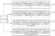
在一实施例中,如图6所示,在S40中,根据第一电平信号和第二电平信号,运算控制模块50、逻辑控制模块40和控制输出模块60执行相应的过流保护策略,包括:In one embodiment, as shown in FIG. 6, in S40, according to the first level signal and the second level signal, the
S41:若第一电平信号为低电平信号,第二电平信号为低电平信号,则运算控制模块正常运算并输出控制输出信号,逻辑控制模块正常控制并输出目标控制指令,控制输出模块基于目标控制指令正常控制输出。S41: If the first level signal is a low-level signal and the second level signal is a low-level signal, the operation control module operates normally and outputs a control output signal, the logic control module normally controls and outputs a target control command, and controls the output The module normally controls the output based on the target control command.
具体地,当第一电平信号为低电平信号,第二电平信号为低电平信号时,运算控制模块50正常运算,并向逻辑控制模块40输出控制输出信号;逻辑控制模块正常控制,并向控制输出模块60输出目标控制指令对控制输出模块60进行控制;控制输出模块60基于目标控制指令正常控制输出。作为一示例,控制输出模块60通过PWM信号的形式进行控制输出。Specifically, when the first level signal is a low level signal and the second level signal is a low level signal, the
具体地,第一电平信号为低电平信号,第二电平信号为低电平信号,第一电压模拟信号小于第一基准电压和第二基准电压,此时换流器功率回路中的逆变电流不存在过流的情况,运算控制模块50正常运算并输出控制输出信号使逻辑控制模块40正常工作,逻辑控制模块40通过正常控制并输出目标控制指令,控制输出模块60正常控制输出PWM信号。Specifically, the first level signal is a low level signal, the second level signal is a low level signal, and the first voltage analog signal is smaller than the first reference voltage and the second reference voltage, at this time, the There is no overcurrent in the inverter current, the
S42:若第一电平信号为高电平信号,第二电平信号为低电平信号,则运算控制模块正常运算并输出控制输出信号,关闭逻辑控制模块,控制输出模块停止控制输出。S42: If the first level signal is a high level signal and the second level signal is a low level signal, the operation control module operates normally and outputs a control output signal, the logic control module is turned off, and the control output module stops control output.
具体地,第一电平信号为高电平信号,第二电平信号为低电平信号,此时,有两种情况:一、实际的逆变电流检测值对应的第一电压模拟信号大于第一基准电压小于第二基准电压,逆变电流过流;二、第一电平信号为高电平信号是由比较模块30对电压模拟信号比较时干扰信号影响的。针对上述的两种情况,为了防止换流器被过流的逆变电流损坏,运算控制模块50通过正常运算并输出控制输出信号;关闭逻辑控制模块40,控制输出模块60停止输出PWM信号,但是不停止运行,在逆变电流检测值恢复到正常值时,能够快速的使控制输出模块60输出PWM信号,提高换流器过流保护电路的效率和可靠性。Specifically, the first level signal is a high level signal, and the second level signal is a low level signal. At this time, there are two situations: 1. The first voltage analog signal corresponding to the actual inverter current detection value is greater than The first reference voltage is lower than the second reference voltage, and the inverter current is overcurrent; 2. The first level signal is a high level signal, which is affected by the interference signal when the
S43:若第一电平信号为低电平信号,第二电平信号为高电平信号,则运算控制模块停止运算和输出控制输出信号,关闭逻辑控制模块,控制输出模块停止控制输出。S43: If the first level signal is a low level signal and the second level signal is a high level signal, the operation control module stops calculation and output control output signal, closes the logic control module, and the control output module stops control output.
具体地,第一电平信号为低电平信号,第二电平信号为高电平信号,此时,有两种情况:一、第一比较单元31异常,未能得到第一电平信号,但是,第二比较单元32得到第二电平信号为高电平信号;二、第二电平信号为高电平信号是由比较模块30对电压模拟信号比较时干扰信号影响的。针对上述的两种情况,为了防止换流器被过流的逆变电流损坏,运算控制模块50通停止运算和输出控制输出信号;关闭逻辑控制模块40关闭,控制输出模块60停止输出PWM信号,在防止干扰信号的情况下,控制输出模块60停止输出PWM信号,但是不停止运行,在逆变电流检测值恢复到正常值时,能够快速的使控制输出模块60输出PWM信号,提高换流器过流保护电路的效率和可靠性。Specifically, the first level signal is a low level signal, and the second level signal is a high level signal. At this time, there are two situations: 1. The
S44:若第一电平信号为高电平信号,第二电平信号为高电平信号,则运算控制模块停止运算和输出控制输出信号,关闭逻辑控制模块并拉断接触器,控制输出模块停机。S44: If the first level signal is a high-level signal and the second level signal is a high-level signal, the operation control module stops the operation and outputs the control output signal, closes the logic control module and pulls off the contactor, and controls the output module shutdown.
具体地,第一电平信号为高电平信号,第二电平信号为高电平信号,逆变电流检测值对应的第一电压模拟信号大于第一基准电压和第二基准电压对应的电流值,可以理解地,此时换流器功率回路中的逆变电流存在过流的情况,运算控制模块50停止运算和关闭控制输出信号,逻辑控制模块40关闭和拉断接触器停机,进而断开换流器功率回路,对换流器起到保护作用;此时,控制输出模块停机,即停止运行。Specifically, the first level signal is a high level signal, the second level signal is a high level signal, and the first voltage analog signal corresponding to the inverter current detection value is greater than the current corresponding to the first reference voltage and the second reference voltage It can be understood that at this time, the inverter current in the power loop of the converter has an overcurrent situation, the
在本实施例中,逻辑控制模块40通过对第一电平信号和第二电平信号对应的高电平信号和低电平信号信号进行逻辑处理,在第一比较单元31异常,未能得到第一电平信号和由比较模块30对电压模拟信号比较时干扰信号影响的情况下,通过接收运算控制模块50的控制输出信号和比较模块30的第一电平信号和第二电平信号对应的高电平信号和低电平信号信号进行逻辑处理,控制控制输出模块60输出PWM信号或停止工作来实现对换流器的过流保护,提高了换流器过流保护电路的的可靠性和安全性。In this embodiment, the
本发明实施例提供一种换流器过流保护电路,是用于换流器功率回路上,如图2所示,换流器过流保护电路包括:电流采样模块10、运放调理模块20、比较模块30、逻辑控制模块40和运算控制模块50;电流采样模块10与换流器功率回路相连接,用于对换流器功率回路的输出电流进行检测,获取电流检测值;运放调理模块20与电流采样模块10、比较模块30和运算控制模块50相连接,用于对电流检测值进行运放调理处理,向比较模块30和运算控制模块50输出电压模拟信号;比较模块30与运放调理模块20和逻辑控制模块40相连接,用于对电压模拟信号进行逻辑比较,获取比较信号,向逻辑控制模块40输出比较信号;运算控制模块50与运放调理模块20和逻辑控制模块40相连接,用于对电压模拟信号进行模数转换和运算处理,获取控制输出信号,向逻辑控制模块40输出控制输出信号;逻辑控制模块40与比较模块30和运算控制模块50相连接,用于对比较信号和控制输出信号进行逻辑处理,输出并执行目标控制指令。The embodiment of the present invention provides a converter overcurrent protection circuit, which is used in the power circuit of the converter. As shown in FIG. 2, the converter overcurrent protection circuit includes: a current sampling module 10, an operational amplifier conditioning module 20 , a comparison module 30, a logic control module 40 and an operation control module 50; the current sampling module 10 is connected with the power loop of the converter, and is used to detect the output current of the power loop of the converter to obtain a current detection value; The module 20 is connected with the current sampling module 10, the comparison module 30 and the operation control module 50, and is used for carrying out the op-amp conditioning process to the current detection value, and outputs the voltage analog signal to the comparison module 30 and the operation control module 50; the comparison module 30 and the operation control module Put conditioning module 20 and logic control module 40 to be connected, be used for carrying out logic comparison to voltage analog signal, obtain comparison signal, output comparison signal to logic control module 40; connected to each other, for analog-to-digital conversion and arithmetic processing of the voltage analog signal, to obtain a control output signal, and to output the control output signal to the logic control module 40; the logic control module 40 is connected to the comparison module 30 and the arithmetic control module 50 for Logically process the comparison signal and the control output signal, output and execute the target control instruction.
其中,电流采样模块10包括电流采集霍尔元件和供电单元。电流采集霍尔元件用于对电流进行采集;供电单元用于对电流采样模块10供电。作为一示例,电流采集霍尔元件可以是T60404-N4646-X461型号电流霍尔元件。运放调理模块20包括运放电路、基准电源、电阻和电容。比较模块30包括比较器、比较阈值电路、电阻和电容。逻辑控制模块40包括CPLD(Complex Programmable Logic Device,复杂可编程逻辑器件,简称CPLD)、控制输出单元、电阻和电容;CPLD可以对信号进行接收、处理和输出。作为一示例,CPLD可以是LAMXO640C型号芯片,能够对PWM信号进行接收、处理和输出。运算控制模块50包括DSP单元和控制输出单元。DSP(Digital Signal Processing,数字信号处理,简称DSP)单元用于以数字形式对信号进行采集、变换、滤波、估值、增强、压缩和识别等处理,以得到符合实际需求的信号形式。作为一示例,DSP对信号处理后得到PWM信号。控制输出单元用于输出DSP单元处理的信号。作为一示例,DSP单元可以包括TMS320F28335芯片。Wherein, the
其中,电流采样模块10与换流器功率回路相连接,用于对换流器功率回路的输出电流进行检测,获取电流检测值。电流检测值为电流采样模块10对换流器功率回路的输出电流进行检测后得到的采样电流。具体地,当换流器功率回路中的输出电流过大时,可能或引起设备或器件的损坏,并产生安全隐患;此时,电流采样模块10中的电流采集霍尔元件对换流器功率回路中的输出电流进行采集和检测,得到电流检测值,使得换流器过流保护电路能够根据电流检测值判断换流器功率回路中的输出电流是否过大,避免引起设备或器件的损坏,产生安全隐患,能有效保证换流器的安全可靠稳定运行。Wherein, the
其中,运放调理模块20与电流采样模块10、比较模块30和运算控制模块50相连接,用于对电流检测值进行运放调理处理,向比较模块30和运算控制模块50输出电压模拟信号。电压模拟信号为运放调理模块20对电流采样模块10检测到的电流检测值进行运放调理后,得到的与电流检测值对应的模拟电压。具体地,运放调理模块20对电流采样模块10检测到的电流检测值进行调理处理的过程,具体是指通过运放电路将电流检测值进行缩放处理后,基于基准电源对电流检测值进行滤波、调理成运算控制模块50中的DSP单元可以识别电压模拟信号,并向比较模块30和运算控制模块50输出电压模拟信号,以使得比较模块30和运算控制模块50能够根据电流检测值对应的电压模拟信号判断换流器功率回路中的输出电流是否过大,避免引起设备或器件的损坏,产生安全隐患。Among them, the operational
其中,比较模块30与运放调理模块20和逻辑控制模块40相连接,用于对电压模拟信号进行逻辑比较,获取比较信号,向逻辑控制模块40输出比较信号。运算控制模块50与运放调理模块20和逻辑控制模块40相连接,用于对电压模拟信号进行模数转换和运算处理,获取控制输出信号,向逻辑控制模块40输出控制输出信号。逻辑控制模块40与比较模块30和运算控制模块50相连接,用于对比较信号和控制输出信号进行逻辑处理,输出并执行目标控制指令。Wherein, the
具体地,比较信号为比较模块30对运放调理模块20输出的电压模拟信号对应的电流检测值进行逻辑比较后形成的信号。控制输出信号为运算控制模块50对电压模拟信号对应的电流检测值进行模数转换和运算处理后形成的信号,用于控制逻辑控制模块40。目标控制指令为根据控制输出信号和比较信号确定的与这两种信号相匹配的预先自定义设置的指令。Specifically, the comparison signal is a signal formed after the
具体地,由于比较模块30和运算控制模块50只能对电压进行识别,所以通过运放调理模块20能够将电流采样模块10获取的电流检测值转换成比较模块30和运算控制模块50能够识别的电压模拟信号,以使在比较模块30和运算控制模块50识别到电压模拟信号后,对电压模拟信号对应的电流检测值进行处理。比较模块30对运放调理模块20输出的电压模拟信号对应的电流检测值进行比较,得到比较信号,并将比较信号输出到逻辑控制模块40,同时,运算控制模块50对运放调理模块20输出的电压模拟信号对应的电流检测值进行模数转换和运算处理后,形成控制输出信号,并将控制输出信号输出到逻辑控制模块40。进一步地,逻辑控制模块40对比较信号和控制输出信号进行逻辑处理,输出目标控制指令,并执行目标控制指令。逻辑控制模块40根据比较模块30输出的比较信号和运算控制模块50输出的控制输出信号来输出并执行目标控制指令,避免了干扰信号对逻辑控制模块40输出的影响,同时,通过逻辑控制模块40来对比较信号进行处理,输出目标控制指令减少了运算控制模块50的任务量,提高了换流器过流保护电路的效率、稳定性和可靠性。Specifically, since the
在本实施例中,电流采样模块10可以通过电流采集霍尔元件对换流器功率回路中的输出电流进行采集和检测,得到电流检测值,使得换流器过流保护电路能够根据电流检测值判断换流器功率回路中的输出电流是否过大并进行安全防护,避免引起设备或器件的损坏,产生安全隐患,能有效保证系统的安全可靠稳定运行。运放调理模块20将电流检测值进行缩放处理后,基于基准电源对电流检测值进行滤波、调理成运算控制模块50中的DSP单元可以识别电压模拟信号,并向比较模块30和运算控制模块50输出电压模拟信号,使得比较模块30和运算控制模块50能够根据电压模拟信号对应的电流检测值判断换流器功率回路中的输出电流是否过大,能有效保证系统的安全可靠稳定运行。逻辑控制模块40根据比较模块30输出的比较信号和运算控制模块50输出的控制输出信号来输出并执行目标控制指令,避免了干扰信号对逻辑控制模块40输出的影响,同时,通过逻辑控制模块40来对比较信号进行处理,输出目标控制指令减少了运算控制模块50的任务量,提高了换流器过流保护电路的效率、稳定性和可靠性。In this embodiment, the
在一实施例中,如图2所示,换流器过流保护电路还包括:控制输出模块60,控制输出模块60与逻辑控制模块40相连,用于执行逻辑控制模块40输出的目标控制指令。In one embodiment, as shown in FIG. 2 , the converter overcurrent protection circuit further includes: a
其中,控制输出模块60包括DSP单元和控制输出单元。Wherein, the
具体地,当控制输出模块60获取逻辑控制模块40输出的目标控制指令,DSP单元对逻辑控制模块40输出的目标控制指令进行分析,并执行目标控制指令,控制输出单元实现换流器功率回路的断开。作为一示例,可以是通过接触器断开换流器功率回路,当目标控制指令为拉断接触器时,控制输出单元根据目标控制指令将外接的接触器拉断,断开换流器功率回路,提高换流器过流保护电路的可靠性。Specifically, when the
在本实施例中,控制输出模块60根据逻辑控制模块40输出的目标控制指令,当换流器功率回路上的电流过大时,控制输出模块60通过断开换流器功率回路,提高了换流器过流保护电路的可靠性。In this embodiment, according to the target control command output by the
在一实施例中,如图2所示,电流采样模块10包括逆变电流采样单元11和电网电流采样单元12;逆变电流采样单元11与换流器功率回路相连,用于对换流器功率回路的逆变电流进行检测,获取逆变电流检测值。运放调理模块20包括第一运放调理单元21;第一运放调理单元21与逆变电流采样单元11、比较模块30和运算控制模块50相连接,用于对逆变电流检测值进行运放调理处理,向比较模块30和运算控制模块50输出第一电压模拟信号。比较模块30与第一运放调理单元21和逻辑控制模块40相连接,用于对第一电压模拟信号进行逻辑比较,获取比较信号,向逻辑控制模块40输出比较信号。In one embodiment, as shown in FIG. 2 , the
其中,逆变电流采样单元11为对换流器功率回路中的逆变电流进行检测的单元。逆变电流为换流器外接电网的电流经过处理后输入到换流器的电流。电网电流采样单元12为对换流器功率回路中的电网电流进行检测的单元。第一运放调理单元21为对逆变电流检测值进行运放调理的单元。第一电压模拟信号为对逆变电流检测值进行运放调理处理形成的信号。Wherein, the inverter current sampling unit 11 is a unit for detecting the inverter current in the power loop of the converter. The inverter current is the current input to the converter after processing the current connected to the grid external to the converter. The grid
具体地,由于换流器对电流进行逆变时,若电流过大,容易损坏换流器并产生安全问题,为避免这一问题出现,本实施例所提供的换流器过流保护电路中,采用逆变电流采样单元11对逆变电流进行检测,得到逆变电流检测值,再将逆变电流检测值输出到第一运放调理单元21。第一运放调理单元21对逆变电流检测值进行运放调理后,获取第一电压模拟信号,并将第一电压模拟信号输出到比较模块30。具体地,第一运放调理单元21通过运放电路将逆变电流检测值进行缩放处理后,基于基准电源对逆变电流检测值进行滤波、调理成运算控制模块50中的DSP单元可以识别第一电压模拟信号,并向比较模块30和运算控制模块50输出第一电压模拟信号。比较模块30对第一运放调理单元21输出的第一电压模拟信号进行比较,得到比较信号,并将比较信号输出到逻辑控制模块40;同时,运算控制模块50对第一运放调理单元21输出的第一电压模拟信号进行模数转换和运算处理后,形成控制输出信号,并将控制输出信号输出到逻辑控制模块40。接着,逻辑控制模块40对比较信号和控制输出信号进行逻辑处理,输出并执行目标控制指令。逻辑控制模块40根据比较模块30输出的比较信号和运算控制模块50输出的控制输出信号来输出并执行目标控制指令,使得换流器过流保护电路能够根据逆变电流检测值判断换流器功率回路中的输出电流是否过大,并通过逻辑控制模块40输出并执行目标控制指令,避免引起设备或器件的损坏,产生安全隐患,能有效保证换流器的安全可靠稳定运行。Specifically, when the converter inverts the current, if the current is too large, it is easy to damage the converter and cause safety problems. In order to avoid this problem, the converter overcurrent protection circuit provided in this embodiment , using the inverter current sampling unit 11 to detect the inverter current to obtain a detection value of the inverter current, and then output the detection value of the inverter current to the first operational
在一实施例中,电流采样模块10还包括电网电流采样单元12,电网电流采样单元12与换流器功率回路相连,用于对换流器功率回路的电网电流进行检测,获取电网电流检测值。运放调理模块20还包括第二运放调理单元22;第二运放调理单元22与电网电流采样单元12、运算控制模块50相连接,用于对电网电流检测值进行运放调理处理,向运算控制模块50输出第二电压模拟信号。运算控制模块50与第二运放调理单元22相连,用于对第二电压模拟信号进行进行模数转换和运算处理,获取控制输出信号,向逻辑控制模块40输出控制输出信号。In one embodiment, the
其中,电网电流为换流器外接电网的电流。逆变电流检测值为逆变电流采样单元11对逆变电流进行检测得到的检测值。电网电流检测值为电网电流采样单元12对电网电流进行检测得到的检测值。第二运放调理单元22为对电网电流检测值进行运放调理的单元。第二电压模拟信号为对电网电流检测值进行运放调理处理形成的信号。Wherein, the grid current is the current of the converter externally connected to the grid. The detection value of the inverter current is a detection value obtained by detecting the inverter current by the inverter current sampling unit 11 . The detected value of the grid current is a detection value obtained by detecting the grid current by the grid
具体地,由于实际需要,用户需要获取电网电流的参数,及时对电网电流进行调整,此时,电网电流采样单元12对电网电流进行检测,得到电网电流检测值,再将电网电流检测值输出到第二运放调理单元22。第二运放调理单元22对电网电流进行运放调理后,将第二电压模拟信号输出到运算控制模块50,运算控制模块50对第二运放调理单元22输出的第二电压模拟信号进行模数转换和运算处理后,形成控制输出信号,并将控制输出信号输出到逻辑控制模块40,控制逻辑控制模块40对电网电流的参数进行输出。本示例中,通过换流器过流保护电路实现对电网电流的分析,及时对电网电流进行调整,提高换流器过流保护电路的安全性。Specifically, due to actual needs, the user needs to obtain the parameters of the grid current and adjust the grid current in time. At this time, the grid
在本实施例中,第二运放调理单元22对电网电流检测值进行运放调理处理,并向运算控制模块50输出第二电压模拟信号,运算控制模块50对第二电压模拟信号对应的电流检测值进行模数转换和运算处理后,形成控制输出信号,并将控制输出信号输出到逻辑控制模块40,控制逻辑控制模块40对电网电流的参数进行输出。使得用户通过逻辑控制模块40对电网电流的参数进行输出,实现对电网电流的分析,及时对电网电流进行调整,提高换流器过流保护电路的安全性。In this embodiment, the second op-
在一实施例中,比较模块30包括第一比较单元31、第二比较单元32、第一阈值电路和第二阈值电路。第一比较单元31的输入端与第一运放调理单元21和第一阈值电路相连,输出端与逻辑控制模块40相连,用于对第一电压模拟信号和第一阈值电路输入的第一基准电压进行比较,获取第一电平信号,并将第一电平信号输出给逻辑控制模块40。第二比较单元32的输入端与第一运放调理单元21相连,输出端与逻辑控制模块40相连,用于对第一电压模拟信号和第二阈值电路输入的第二基准电压进行比较,获取第二电平信号,并将第二电平信号输出给逻辑控制模块40。In one embodiment, the
其中,第一电平信号为第一电压模拟信号与第一基准电压比较形成的信号。第二电平信号为第一电压模拟信号与第二基准电压比较形成的信号。第一基准电压和第二基准电压为用户根据实际需求预设的电压。第一阈值电路和第二阈值电路分别用于提供第一基准电压和第二基准电压。第一比较单元31用于对第一电压模拟信号和第一基准电压进行比较,获取第一电平信号。第二比较单元32用于第一电压模拟信号和第二基准电压进行比较,获取第二电平信号。Wherein, the first level signal is a signal formed by comparing the first voltage analog signal with the first reference voltage. The second level signal is a signal formed by comparing the first voltage analog signal with the second reference voltage. The first reference voltage and the second reference voltage are voltages preset by the user according to actual needs. The first threshold circuit and the second threshold circuit are used to provide the first reference voltage and the second reference voltage respectively. The
具体的,第一运放调理单元21向第一比较单元31和第二比较单元32输出第一电压模拟信号后,第一比较单元31通过第一阈值电路输入的第一基准电压与第一电压模拟信号进行比较,得到第一电平信号;并将第一电平信号输出给逻辑控制模块40进行进一步处理。第二比较单元32通过第二阈值电路输入的第二基准电压与第一电压模拟信号进行比较,得到第二电平信号。并将第二电平信号输出给逻辑控制模块40进行进一步处理。可以理解地,由于第一比较单元31和第二比较单元32只能对电路中的电压进行识别,所以第一比较单元31或第二比较单元32通过第一电压模拟信号与第一基准电压或第二基准电压进行比较,来判断逆变电流是否过流,以实现对换流器的过流保护。Specifically, after the first operational
作为一示例,第一阈值电路提供的第一基准电压为REF1,第二阈值电路提供的第二基准电压为REF2。需要说明的是,由于第一基准电压和第二基准电压均需要与第一电压模拟信号进行比较,为避免两者比较信号相同,需使第一基准电压和第二基准电压不相同。本示例中,可设置第一基准电压小于第二基准电压。As an example, the first reference voltage provided by the first threshold circuit is REF1, and the second reference voltage provided by the second threshold circuit is REF2. It should be noted that since both the first reference voltage and the second reference voltage need to be compared with the first voltage analog signal, in order to avoid the same comparison signals, the first reference voltage and the second reference voltage need to be different. In this example, the first reference voltage can be set to be smaller than the second reference voltage.
可以理解地,为了避免判断逆变电流检测值实时过流时,因为干扰信号,或者逆变电流检测值不稳定的情况下,触发换流器过流保护电路对换流器的保护断开换流器功率回路,使换流器功率回路停止运行,使换流器功率回路运行不稳定。比较模块30通过第一基准电压和第二基准电压与第一电压模拟信号进行比较,避免了电路中的干扰信号与第一基准电压或者第二基准电压比较后,使逻辑控制模块40对干扰信号进行误判使换流器功率回路停止工作,提高换流器过流保护的可靠性。Understandably, in order to avoid judging the real-time overcurrent of the inverter current detection value, the inverter overcurrent protection circuit is triggered to disconnect the protection of the inverter due to interference signals, or the inverter current detection value is unstable. The power circuit of the converter, so that the power circuit of the converter is stopped, and the operation of the power circuit of the converter is unstable. The
在本实施例中,第一比较单元31通过第一阈值电路输入的第一基准电压与第一电压模拟信号进行比较,得到第一电平信号,并将第一电平信号输出给逻辑控制模块40进行进一步处理。第二比较单元32通过第二阈值电路输入的第二基准电压与第一电压模拟信号进行比较,得到第二电平信号,并将第二电平信号输出给逻辑控制模块40进行进一步处理。本示例中,将第一电平信号和第二电平信号这两个比较信号输出给逻辑控制模块40进行进一步处理,避免了第一电压模拟信号超过一次第一基准电压或者第二基准电压就通过逻辑控制模块40使换流器功率回路停止工作,提高换流器过流保护的可靠性。In this embodiment, the
在一实施例中,如图2所示,电流采样模块10还包括滤波电路13和接触器;滤波电路13与换流器功率回路相连,用于对换流器功率回路输出的信号进行滤波;接触器与滤波电路13和电网相连,并与逻辑控制模块40相连,用于在逻辑控制模块40的控制下断开或导通。In one embodiment, as shown in FIG. 2 , the
其中,滤波电路13包括滤波电容和滤波电感形成的LC滤波电路13。本示例中,滤波电路13包括设置在换流器功率回路的A相输出的第一滤波电路13、设置在换流器功率回路的B相输出的第二滤波电路13、以及设置在换流器功率回路的C相输出的第三滤波电路13。相应地,接触器包括设置在换流器功率回路的A相输出上的与第一滤波电路13相连的第一接触器K1、设置在换流器功率回路的B相输出上的与第二滤波电路13相连的第二接触器K2、以及在换流器功率回路的C相输出上的与第三滤波电路13相连的第三接触器K3。如图2所示,第一滤波电路13包括第一滤波电感L1和第一滤波电容C1;第一滤波电感L1与第一接触器K1串联设置在换流器功率回路的A相输出上;第一滤波电容C1一端与第一滤波电感L1与第一接触器K1相连,另一端接地。第二滤波电路13包括第二滤波电感L2和第二滤波电容C2;第二滤波电感L2和第二接触器K2串联设置在换流器功率回路的B相输出上;第二滤波电容C2一端与第二滤波电感L2和第二接触器K2相连,另一端接地。第三滤波电路13包括第三滤波电感L3和第三滤波电容C3;第三滤波电感L3与第三接触器K3串联设置在换流器功率回路的C相输出上;第三滤波电容C3一端与第三滤波电感L3与第三接触器K3相连,另一端接地。第一接触器K1、第二接触器K2和第三接触器K3与滤波电路13、逻辑控制模块40和电网相连,当换流器功率回路输出的电流过流时,通过逻辑控制模块40将第一接触器K1、第二接触器K2和第三接触器K3断开,提高换流器过流保护的可靠性。Wherein, the
在本实施例中,滤波电路13与换流器功率回路和接触器相连,滤波电路13能够对换流器功率回路中的电压信号进行滤波,使换流器功率回路输出的电压更加稳定,提高了换流器过流保护电路的可靠性;接触器与滤波电路13、逻辑控制模块40和电网相连,当换流器功率回路输出的电流过流时,通过逻辑控制模块40将接触器断开,提高换流器过流保护的可靠性。In this embodiment, the
在一个实施例中,提供了一种换流器控制器,其内部结构图可以如图7所示。该换流器控制器包括通过系统总线连接的处理器、存储器、网络接口和数据库。其中,该换流器控制器的处理器用于提供计算和控制能力。该换流器控制器的存储器包括非易失性存储介质、内存储器。该非易失性存储介质存储有操作系统、逻辑控制程序和数据库。该内存储器为非易失性存储介质中的操作系统和逻辑控制程序的运行提供环境。该换流器控制器的数据库用于换流器过流保护。该计算机设备的网络接口用于与外部的终端通过网络连接通信。该逻辑控制程序被处理器执行时以实现一种换流器过流保护方法方法。In one embodiment, a converter controller is provided, the internal structure diagram of which may be as shown in FIG. 7 . The inverter controller includes a processor, a memory, a network interface and a database connected through a system bus. Wherein, the processor of the converter controller is used to provide calculation and control capabilities. The memory of the inverter controller includes a non-volatile storage medium and an internal memory. The non-volatile storage medium stores an operating system, a logic control program and a database. The internal memory provides an environment for the operation of the operating system and the logic control program in the non-volatile storage medium. The inverter controller's database is used for inverter overcurrent protection. The network interface of the computer device is used to communicate with an external terminal via a network connection. When the logic control program is executed by the processor, an inverter overcurrent protection method is realized.
在一个实施例中,提供了一种换流器控制器,包括存储器、处理器及存储在存储器上并可在处理器上运行的逻辑控制程序,处理器执行逻辑控制程序时实现上述实施例中换流器过流保护方法方法,例如步骤S10至步骤S40,为避免重复,这里不再赘述。In one embodiment, a converter controller is provided, including a memory, a processor, and a logic control program stored in the memory and operable on the processor. When the processor executes the logic control program, the above embodiments are implemented. The converter overcurrent protection method, such as step S10 to step S40, will not be repeated here to avoid repetition.
以上所述实施例仅用以说明本发明的技术方案,而非对其限制;尽管参照前述实施例对本发明进行了详细的说明,本领域的普通技术人员应当理解:其依然可以对前述各实施例所记载的技术方案进行修改,或者对其中部分技术特征进行等同替换;而这些修改或者替换,并不使相应技术方案的本质脱离本发明各实施例技术方案的精神和范围,均应包含在本发明的保护范围之内。The above-described embodiments are only used to illustrate the technical solutions of the present invention, rather than to limit them; although the present invention has been described in detail with reference to the foregoing embodiments, those of ordinary skill in the art should understand that: it can still implement the foregoing embodiments Modifications to the technical solutions recorded in the examples, or equivalent replacement of some of the technical features; and these modifications or replacements do not make the essence of the corresponding technical solutions deviate from the spirit and scope of the technical solutions of the various embodiments of the present invention, and should be included in within the protection scope of the present invention.
Claims (9)
Translated fromChinesePriority Applications (1)
| Application Number | Priority Date | Filing Date | Title |
|---|---|---|---|
| CN202010476926.3ACN113746066B (en) | 2020-05-29 | 2020-05-29 | Current converter overcurrent protection method and circuit and current converter controller |
Applications Claiming Priority (1)
| Application Number | Priority Date | Filing Date | Title |
|---|---|---|---|
| CN202010476926.3ACN113746066B (en) | 2020-05-29 | 2020-05-29 | Current converter overcurrent protection method and circuit and current converter controller |
Publications (2)
| Publication Number | Publication Date |
|---|---|
| CN113746066A CN113746066A (en) | 2021-12-03 |
| CN113746066Btrue CN113746066B (en) | 2022-12-09 |
Family
ID=78724732
Family Applications (1)
| Application Number | Title | Priority Date | Filing Date |
|---|---|---|---|
| CN202010476926.3AActiveCN113746066B (en) | 2020-05-29 | 2020-05-29 | Current converter overcurrent protection method and circuit and current converter controller |
Country Status (1)
| Country | Link |
|---|---|
| CN (1) | CN113746066B (en) |
Families Citing this family (1)
| Publication number | Priority date | Publication date | Assignee | Title |
|---|---|---|---|---|
| CN115313312A (en)* | 2022-08-19 | 2022-11-08 | 江苏天合储能有限公司 | A kind of protection method and device of three-level converter |
Citations (5)
| Publication number | Priority date | Publication date | Assignee | Title |
|---|---|---|---|---|
| CN104218535A (en)* | 2013-05-31 | 2014-12-17 | 浙江三花股份有限公司 | An active PFC over-current protection circuit |
| WO2015095400A1 (en)* | 2013-12-17 | 2015-06-25 | Integrated Device Technology, Inc. | Apparatuses and methods for over-current protection of dc-dc voltage converters |
| CN206272224U (en)* | 2016-12-15 | 2017-06-20 | 新誉轨道交通科技有限公司 | Three-phase inverter output overcurrent protection circuit and three-phase inversion system |
| CN107147094A (en)* | 2017-04-27 | 2017-09-08 | 华为技术有限公司 | Current limiting protection circuit and protection method |
| CN207518263U (en)* | 2017-07-21 | 2018-06-19 | 深圳市沃特玛电池有限公司 | A kind of current foldback circuit |
Family Cites Families (2)
| Publication number | Priority date | Publication date | Assignee | Title |
|---|---|---|---|---|
| CN101924362B (en)* | 2009-06-16 | 2014-11-05 | 快捷半导体有限公司 | Over-current protection circuit with foldback capability |
| CN105514938B (en)* | 2014-09-23 | 2018-06-15 | 江森自控空调冷冻设备(无锡)有限公司 | For the overcurrent protection method and overcurrent protection circuit of DC frequency-changing driver |
- 2020
- 2020-05-29CNCN202010476926.3Apatent/CN113746066B/enactiveActive
Patent Citations (5)
| Publication number | Priority date | Publication date | Assignee | Title |
|---|---|---|---|---|
| CN104218535A (en)* | 2013-05-31 | 2014-12-17 | 浙江三花股份有限公司 | An active PFC over-current protection circuit |
| WO2015095400A1 (en)* | 2013-12-17 | 2015-06-25 | Integrated Device Technology, Inc. | Apparatuses and methods for over-current protection of dc-dc voltage converters |
| CN206272224U (en)* | 2016-12-15 | 2017-06-20 | 新誉轨道交通科技有限公司 | Three-phase inverter output overcurrent protection circuit and three-phase inversion system |
| CN107147094A (en)* | 2017-04-27 | 2017-09-08 | 华为技术有限公司 | Current limiting protection circuit and protection method |
| CN207518263U (en)* | 2017-07-21 | 2018-06-19 | 深圳市沃特玛电池有限公司 | A kind of current foldback circuit |
Also Published As
| Publication number | Publication date |
|---|---|
| CN113746066A (en) | 2021-12-03 |
Similar Documents
| Publication | Publication Date | Title |
|---|---|---|
| CN108761319B (en) | Relay failure detection method, device and system for photovoltaic grid-connected inverter | |
| CN201789275U (en) | Inverter overcurrent protection circuit | |
| CN109406989B (en) | Load loop detection method, load detection circuit and electronic equipment | |
| CN104682394B (en) | Electric-dazzling prevention device and method of bidirectional zero-clearance conversion current based on self-adaption | |
| CN109103891B (en) | Voltage sag treatment system and voltage sag compensation control method and device | |
| CN109981030A (en) | Bus overvoltage protection circuit, control method and magnetic suspension compressor | |
| CN104270026A (en) | Three-level wave-by-wave current limiting control method and system | |
| CN102843060A (en) | Two-level two-direction current transformer and control method thereof | |
| CN113138351B (en) | Modular multilevel converter capacitor monitoring method based on sub-module input time | |
| CN113746066B (en) | Current converter overcurrent protection method and circuit and current converter controller | |
| CN114498548B (en) | Overcurrent protection method and device | |
| CN107947122A (en) | The fault tolerant control method of UPS load currents collection failure and the device of application this method | |
| CN104600682B (en) | Active power filter current protection circuit and method | |
| WO2025087213A1 (en) | Arc fault detection method, direct-current voltage converter, and energy storage device | |
| CN117977698B (en) | Control method of bidirectional AC/DC converter and power equipment | |
| CN105510841A (en) | System for online monitoring and managing electric quantity of underwater equipment power supply | |
| JP2020036511A (en) | Power conditioner | |
| CN118693827A (en) | Active filter fault diagnosis and active fault-tolerant control method, system and storage medium | |
| CN210468790U (en) | Flexible direct current power module overvoltage protection circuit | |
| AU2018286627B2 (en) | Method for detecting earth-fault conditions in a power conversion apparatus | |
| CN205489498U (en) | Overcurrent protection circuit | |
| CN103795064B (en) | A kind of high voltage direct current transmission project AC voltage sampling control method and device | |
| CN102608470B (en) | Judge the method and system of stability of active power filer | |
| CN116191383B (en) | An overcurrent protection method and circuit | |
| CN112816805A (en) | Flexible direct current converter valve control system and over-current detection method and system |
Legal Events
| Date | Code | Title | Description |
|---|---|---|---|
| PB01 | Publication | ||
| PB01 | Publication | ||
| SE01 | Entry into force of request for substantive examination | ||
| SE01 | Entry into force of request for substantive examination | ||
| GR01 | Patent grant | ||
| GR01 | Patent grant |