CN113733596B - Composite material light undercarriage wheel structure and forming mode thereof - Google Patents
Composite material light undercarriage wheel structure and forming mode thereofDownload PDFInfo
- Publication number
- CN113733596B CN113733596BCN202111006857.0ACN202111006857ACN113733596BCN 113733596 BCN113733596 BCN 113733596BCN 202111006857 ACN202111006857 ACN 202111006857ACN 113733596 BCN113733596 BCN 113733596B
- Authority
- CN
- China
- Prior art keywords
- carbon fiber
- wheel hub
- mold
- hub
- tire
- Prior art date
- Legal status (The legal status is an assumption and is not a legal conclusion. Google has not performed a legal analysis and makes no representation as to the accuracy of the status listed.)
- Active
Links
Images


Classifications
- B—PERFORMING OPERATIONS; TRANSPORTING
- B29—WORKING OF PLASTICS; WORKING OF SUBSTANCES IN A PLASTIC STATE IN GENERAL
- B29C—SHAPING OR JOINING OF PLASTICS; SHAPING OF MATERIAL IN A PLASTIC STATE, NOT OTHERWISE PROVIDED FOR; AFTER-TREATMENT OF THE SHAPED PRODUCTS, e.g. REPAIRING
- B29C70/00—Shaping composites, i.e. plastics material comprising reinforcements, fillers or preformed parts, e.g. inserts
- B29C70/04—Shaping composites, i.e. plastics material comprising reinforcements, fillers or preformed parts, e.g. inserts comprising reinforcements only, e.g. self-reinforcing plastics
- B29C70/28—Shaping operations therefor
- B29C70/30—Shaping by lay-up, i.e. applying fibres, tape or broadsheet on a mould, former or core; Shaping by spray-up, i.e. spraying of fibres on a mould, former or core
- B29C70/34—Shaping by lay-up, i.e. applying fibres, tape or broadsheet on a mould, former or core; Shaping by spray-up, i.e. spraying of fibres on a mould, former or core and shaping or impregnating by compression, i.e. combined with compressing after the lay-up operation
- B29C70/342—Shaping by lay-up, i.e. applying fibres, tape or broadsheet on a mould, former or core; Shaping by spray-up, i.e. spraying of fibres on a mould, former or core and shaping or impregnating by compression, i.e. combined with compressing after the lay-up operation using isostatic pressure
- B—PERFORMING OPERATIONS; TRANSPORTING
- B29—WORKING OF PLASTICS; WORKING OF SUBSTANCES IN A PLASTIC STATE IN GENERAL
- B29C—SHAPING OR JOINING OF PLASTICS; SHAPING OF MATERIAL IN A PLASTIC STATE, NOT OTHERWISE PROVIDED FOR; AFTER-TREATMENT OF THE SHAPED PRODUCTS, e.g. REPAIRING
- B29C70/00—Shaping composites, i.e. plastics material comprising reinforcements, fillers or preformed parts, e.g. inserts
- B29C70/04—Shaping composites, i.e. plastics material comprising reinforcements, fillers or preformed parts, e.g. inserts comprising reinforcements only, e.g. self-reinforcing plastics
- B29C70/28—Shaping operations therefor
- B29C70/30—Shaping by lay-up, i.e. applying fibres, tape or broadsheet on a mould, former or core; Shaping by spray-up, i.e. spraying of fibres on a mould, former or core
- B29C70/34—Shaping by lay-up, i.e. applying fibres, tape or broadsheet on a mould, former or core; Shaping by spray-up, i.e. spraying of fibres on a mould, former or core and shaping or impregnating by compression, i.e. combined with compressing after the lay-up operation
- B29C70/345—Shaping by lay-up, i.e. applying fibres, tape or broadsheet on a mould, former or core; Shaping by spray-up, i.e. spraying of fibres on a mould, former or core and shaping or impregnating by compression, i.e. combined with compressing after the lay-up operation using matched moulds
- B—PERFORMING OPERATIONS; TRANSPORTING
- B64—AIRCRAFT; AVIATION; COSMONAUTICS
- B64C—AEROPLANES; HELICOPTERS
- B64C25/00—Alighting gear
- B64C25/32—Alighting gear characterised by elements which contact the ground or similar surface
- B64C25/34—Alighting gear characterised by elements which contact the ground or similar surface wheeled type, e.g. multi-wheeled bogies
- B64C25/36—Arrangements or adaptations of wheels, tyres or axles in general
- B—PERFORMING OPERATIONS; TRANSPORTING
- B29—WORKING OF PLASTICS; WORKING OF SUBSTANCES IN A PLASTIC STATE IN GENERAL
- B29L—INDEXING SCHEME ASSOCIATED WITH SUBCLASS B29C, RELATING TO PARTICULAR ARTICLES
- B29L2031/00—Other particular articles
- B29L2031/30—Vehicles, e.g. ships or aircraft, or body parts thereof
- B29L2031/3076—Aircrafts
- Y—GENERAL TAGGING OF NEW TECHNOLOGICAL DEVELOPMENTS; GENERAL TAGGING OF CROSS-SECTIONAL TECHNOLOGIES SPANNING OVER SEVERAL SECTIONS OF THE IPC; TECHNICAL SUBJECTS COVERED BY FORMER USPC CROSS-REFERENCE ART COLLECTIONS [XRACs] AND DIGESTS
- Y02—TECHNOLOGIES OR APPLICATIONS FOR MITIGATION OR ADAPTATION AGAINST CLIMATE CHANGE
- Y02T—CLIMATE CHANGE MITIGATION TECHNOLOGIES RELATED TO TRANSPORTATION
- Y02T50/00—Aeronautics or air transport
- Y02T50/40—Weight reduction
Landscapes
- Engineering & Computer Science (AREA)
- Mechanical Engineering (AREA)
- Chemical & Material Sciences (AREA)
- Composite Materials (AREA)
- Aviation & Aerospace Engineering (AREA)
- Moulding By Coating Moulds (AREA)
Abstract
Translated fromChinese
Description
Translated fromChinese技术领域technical field
本发明属于飞行器设计领域,涉及一种超轻型光伏飞机起落架轮的结构及其成型方式。The invention belongs to the field of aircraft design, and relates to a structure of an ultra-light photovoltaic aircraft landing gear wheel and a molding method thereof.
背景技术Background technique
光伏飞机完全依赖太阳能及储能电池飞行,然而现阶段储能电池比能量远小于化石燃料,且太阳光转化功率有限,这要求光伏飞机达到极小的结构质量密度以降低飞行功率、提高机翼面积以增加太阳能接受量。因此光伏飞机往往尺寸较大,但总质量相对很小;进而起落架轮虽需求尺寸较大,但承力需求相对很小,且要求重量尽可能小。常规飞机的机轮已无法应用于光伏飞机。若能发挥碳纤维复合材料比强度、比刚度高、可设计性好的特点,将为光伏飞机起落架轮结构提供重要解决方案。Photovoltaic aircraft completely rely on solar energy and energy storage batteries to fly. However, at this stage, the specific energy of energy storage batteries is much smaller than that of fossil fuels, and the conversion power of sunlight is limited, which requires photovoltaic aircraft to achieve a very small structural mass density to reduce flight power and improve wings. area to increase the amount of solar energy received. Therefore, photovoltaic aircraft are often large in size, but the total mass is relatively small; and although the landing gear wheel needs to be large in size, the load-bearing requirements are relatively small, and the weight is required to be as small as possible. The wheels of conventional aircraft can no longer be applied to photovoltaic aircraft. If the characteristics of carbon fiber composite material with high specific strength, high specific stiffness and good designability can be brought into play, it will provide an important solution for the wheel structure of photovoltaic aircraft landing gear.
发明内容SUMMARY OF THE INVENTION
针对上述问题,本发明提出了一种碳纤维复合材料起落架轮结构,并针对此结构提出了适应的成型方法,能在保证机轮达到光伏飞机使用需求的前提下,大大减小结构质量,提升飞机的性能。In view of the above problems, the present invention proposes a carbon fiber composite landing gear wheel structure, and proposes an adaptive molding method for this structure, which can greatly reduce the structural quality and improve the aircraft performance.
本发明复合材料轻质起落架机轮结构成型方式,具体如下:The molding method of the composite lightweight landing gear wheel structure of the present invention is as follows:
首先,成型左轮毂,并用相同方法成型右轮毂,成型方法为:First, shape the left wheel hub, and use the same method to shape the right wheel hub, the molding method is:
A、轮毂结构设计A. Wheel structure design
轮毂结构为具有左、中、右三层结构;左侧与右侧为碳纤维布,中层为泡沫夹层;泡沫夹层设计为舵盘型结构;同时设计在轮毂中心位置具有同轴的金属管。The wheel hub structure has three layers: left, middle and right; the left and right sides are carbon fiber cloth, and the middle layer is a foam interlayer; the foam interlayer is designed as a rudder-type structure; at the same time, a coaxial metal tube is designed in the center of the wheel hub.
B、轮毂成型方式设计B. Design of wheel hub forming method
轮毂的成型方式以整个轮毂纵截面分割的左侧半轮毂结构与右侧半轮毂结构单独成型后,进一步成型整个轮毂结构。其中,左侧半轮毂结构包括泡沫夹层左半部与左侧碳纤维布;右侧半轮毂结构包括泡沫夹层右半部与右侧碳纤维布。The forming method of the wheel hub is that after the left half-hub structure and the right half-hub structure divided by the longitudinal section of the entire wheel hub are separately formed, the entire wheel hub structure is further formed. Among them, the left half hub structure includes the left half of the foam interlayer and the left carbon fiber cloth; the right half hub structure includes the right half of the foam interlayer and the right carbon fiber cloth.
C、轮毂成型所需模具设计C. Mold design required for wheel hub forming
设计模具包括用于两侧轮毂成型的下模具与上模具;上模具与下模具上表面均具有与泡沫夹层结构尺寸相同的阴模部分,且阴模部分的中心孔内径设计为与金属管外径尺寸匹配。The design mold includes a lower mold and an upper mold for forming the hubs on both sides; the upper surfaces of the upper mold and the lower mold have a female mold part with the same size as the foam sandwich structure, and the inner diameter of the center hole of the female mold part is designed to be the same as the outer diameter of the metal tube. Diameter size matching.
D、步骤B中设计的左侧半轮毂与右侧半轮毂成型方式设计,具体为:D. The design of the left half wheel hub and the right half wheel hub designed in step B is as follows:
左半侧轮毂成型设计:Left half wheel forming design:
a、在下模具的上表面铺设所多张涂覆树脂的碳纤维布,使达到需求厚度。a. Lay multiple sheets of carbon fiber cloth coated with resin on the upper surface of the lower mold to achieve the required thickness.
b、将泡沫夹层左半部外侧面嵌入安装于下模具的阴模部分内,压紧碳纤维布。b. Insert the outer side of the left half of the foam interlayer into the female part of the lower mold, and press the carbon fiber cloth.
c、将金属管插入中心孔内,与中心孔内壁碳纤维布成紧配合。c. Insert the metal tube into the center hole and form a tight fit with the carbon fiber cloth on the inner wall of the center hole.
右侧半轮毂的成形设计与左半侧轮毂成型近似,将泡沫夹层右半部将右侧碳纤维布压紧于上模具内即可;由于左右两侧半轮毂共使用一个金属管,因此右侧半轮毂的成形过程中不具备步骤c中金属管的安装过程。The forming design of the right half wheel hub is similar to that of the left half wheel hub. Just press the right half of the foam interlayer and the right carbon fiber cloth into the upper mold; The forming process of the half-wheel hub does not have the installation process of the metal tube in step c.
E、合模、模压固化过程实现整体轮毂成型。E. The mold clamping, molding and curing process realizes the overall wheel hub forming.
首先,上模具与下模具上的中间夹层形状对称,完成合模;随后下模具与上模具加压力与加热,等待完成模压固化。First, the shape of the middle sandwich on the upper mold and the lower mold is symmetrical to complete the mold closing; then the lower mold and the upper mold are pressurized and heated, waiting for the molding and curing to be completed.
F、轮胎支撑环与轮胎间的成型设计。F. The molding design between the tire support ring and the tire.
首先设计轮胎为泡沫轮胎,轮胎内环表面铺设碳纤维布,形成内支撑环;Firstly, the tire is designed as a foam tire, and carbon fiber cloth is laid on the surface of the inner ring of the tire to form an inner support ring;
随后,将内支撑环两侧周向边缘向外侧翻边至泡沫轮胎内环侧部;并在内环侧部沿周向增铺适量碳纤维丝,使内环侧部沿径向碳纤维布厚度均匀。Then, the circumferential edges on both sides of the inner support ring were flanged to the side of the inner ring of the foam tire; and an appropriate amount of carbon fiber filaments were added circumferentially on the side of the inner ring to make the thickness of the carbon fiber cloth uniform along the radial direction of the side of the inner ring.
最后,使用真空袋固化成形。Finally, it is cured into shape using a vacuum bag.
G、左轮毂、右轮毂与轮毂间的安装方式设计;G. Design of the installation method between the left hub, the right hub and the hub;
将左轮毂与右轮毂分别置于轮胎支撑环两侧,使轮毂外围的碳纤维布与轮胎支撑环周向接触,接触位置涂覆树脂胶粘剂,并施加压力以增强胶粘效果,直至完全固化。Place the left wheel hub and the right wheel hub on both sides of the tire support ring, so that the carbon fiber cloth on the periphery of the wheel hub is in circumferential contact with the tire support ring.
本发明的优点在于:The advantages of the present invention are:
1、本发明复合材料轻质起落架机轮结构,采用了薄壁碳纤维复合材料包裹PMI泡沫的高效承力结构,相比传统机轮,在重量上有显著优势。1. The lightweight landing gear wheel structure of the composite material of the present invention adopts a high-efficiency load-bearing structure of a thin-walled carbon fiber composite material wrapped with PMI foam, which has a significant advantage in weight compared with the traditional wheel.
2、本发明复合材料轻质起落架机轮结构及其成型方式,成型过程简单,充分发挥了碳纤维高比强度、高可设计性的特点,且成本低,特别适用于光伏飞机以及其他轻质无人飞行器。2. The composite material lightweight landing gear wheel structure and its molding method of the present invention have a simple molding process, give full play to the characteristics of high specific strength and high designability of carbon fiber, and have low cost, and are especially suitable for photovoltaic aircraft and other lightweight unmanned aerial vehicle.
3、本发明复合材料机轮结构的成型方式,使模具得到了充分而合理的利用,复合材料零件成型过程与装配固化过程共用了一套模具,降低了工艺复杂程度的同时,也使模具成本大大降低。3. The molding method of the composite wheel structure of the present invention enables the mold to be fully and reasonably used. The molding process of the composite material part and the assembly and curing process share a set of molds, which reduces the complexity of the process and reduces the cost of the mold. Greatly reduced.
附图说明Description of drawings
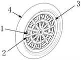
图1为本发明复合材料轻质起落架机轮结构整体示意图;Fig. 1 is the overall schematic diagram of the wheel structure of the composite material lightweight landing gear of the present invention;
图2为本发明复合材料轻质起落架机轮结构爆炸示意图;Figure 2 is a schematic exploded view of the wheel structure of the composite material lightweight landing gear of the present invention;
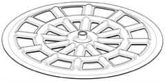
图3为本发明复合材料轻质起落架机轮结构成型所用下模具结构示意图;3 is a schematic structural diagram of a lower mold used for forming the wheel structure of the composite material lightweight landing gear according to the present invention;
图4为本发明复合材料轻质起落架机轮结构半个轮毂的铺布方式分解图;Fig. 4 is an exploded view of the spreading method of the half hub of the composite material lightweight landing gear wheel structure of the present invention;
图5为本发明复合材料轻质起落架机轮结构成型所用上模具结构示意图;5 is a schematic structural diagram of an upper mold used for forming the wheel structure of the composite material lightweight landing gear according to the present invention;
轮毂合模示意图Schematic diagram of wheel hub clamping
图6为本发明复合材料轻质起落架机轮结构成型过程中单个轮毂合模示意图;6 is a schematic diagram of mold clamping of a single wheel hub during the molding process of the composite lightweight landing gear wheel structure of the present invention;
图7为本发明复合材料轻质起落架机轮结构成型后的单个轮毂示意图;7 is a schematic diagram of a single wheel hub after the wheel structure of the composite material lightweight landing gear is formed;
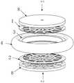
图8为本发明复合材料轻质起落架机轮结构中泡沫轮胎与其内支撑环固化方式示意图;8 is a schematic diagram of the curing method of the foam tire and its inner support ring in the composite lightweight landing gear wheel structure of the present invention;
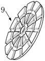
图9为本发明复合材料轻质起落架机轮结构中轮毂-轮胎固化方式示意图。FIG. 9 is a schematic diagram of the hub-tire curing method in the composite lightweight landing gear wheel structure of the present invention.
图中:In the picture:
1-左轮毂 2-右轮毂 3-轮胎支撑环1-left hub 2-right hub 3-tire support ring
4-轮胎 5-碳纤维布 6-中间夹层4-Tire 5-Carbon fiber cloth 6-Interlayer
7-铜管 8-下模具 9-同轴校准模具7-copper tube 8-lower die 9-coaxial alignment die
10-上模具 801-圆盘底座 802-阴模部分10-upper mold 801-disc base 802-female mold part
803-中心孔 901-圆形凹槽 902-校准轴803-Center hole 901-Circular groove 902-Alignment shaft
具体实施方式Detailed ways
下面结合附图对本发明作进一步说明。The present invention will be further described below in conjunction with the accompanying drawings.
本发明复合材料轻质机轮结构,由左轮毂1、右轮毂2、轮胎支撑环3与轮胎4组成,如图1、图2所示。The composite material lightweight wheel structure of the present invention is composed of a
所述左轮毂1与右轮毂2为结构尺寸相同的圆盘结构,具有左、中、右3层结构。左侧与右侧为碳纤维布5,碳纤维布5为薄壁结构,采用碳纤维编织布-树脂复合材料;中间为PMI泡沫夹层6。其中,中间夹层6结构如下:The
中间夹层6为舵盘型结构,具有同心共面的外环与内环。内环与外环间周向等角度间隔设计有12根柱状内支撑梁,12根内支撑梁轴线均过内环与外环中心点,两端分别与内环和外环相接。外环外侧同样设计有12根外支撑梁,12根外支撑梁分别与12根内支撑梁同轴设置,内端与外环外侧相接。The
上述中间夹层6左右两侧为碳纤维布5。两侧碳纤维布5在中间夹层6中相邻内支撑梁之间、相邻外支撑梁之间以及内环内侧的镂空部分处贴合,同时在两侧碳纤维布5上,位于内环内侧部分的中心位置开孔,用于插入铜管7。上述碳纤维布5主要起承力作用,由中间夹层6进行支撑与维形,一方面使中间夹层6两侧的碳纤维布5在内圈与外圈位置形成周向12个双半圆截面的支撑梁结构;另一方面限制了碳纤维布的面外变形,两方面均能有效防止碳纤维布失稳,进而充分发挥碳纤维的承力能力,有效减小结构质量。上述结构的左轮毂1与右轮毂2同轴设置于轮胎支撑环3内,分别位于轮胎支撑环3左右两侧,且中间夹层6的外支撑梁外端与轮胎支撑环3内壁周向相接。轮胎支撑环3外侧同轴套接轮胎。The left and right sides of the above-mentioned
本发明中左轮毂1与右轮毂2的成型方式相同,分别制作以整个轮毂纵截面分割的左侧半轮毂结构与右侧半轮毂结构,进一步制作整体轮毂结构。其中,左侧半轮毂结构包括中间夹层6左半部与左侧碳纤维布5;右侧半轮毂结构包括中间夹层6右半部与右侧碳纤维布5,下面对左侧半轮毂成形方式进行说明,具体方法如下:In the present invention, the
步骤1:根据具体载荷大小,通过有限元法计算确定碳纤维布的铺设厚度,根据所需厚度将多张左侧碳纤维布5逐层涂覆树脂并铺覆于下模具8的上表面。在本发明结构设计下,峰值1000N的落震载荷大约需要0.6mm厚的碳纤维布;而标准碳纤维布规格一般为0.1mm或0.2mm一层,因此针对峰值1000N的落震载荷选择6张0.1mm厚碳纤维布5或3张0.2mm厚碳纤维布。如图3所示,下模具8具有圆盘底座801,圆盘底座801上设计有结构尺寸与中间夹层6左半部外表面轮廓匹配的阴模部分802,其中心孔803内径设计为与铜管7外径尺寸匹配大小,外支撑梁部分端部阴模部分802周向外壁相通。Step 1: According to the specific load, the laying thickness of the carbon fiber cloth is determined by the finite element method, and the left
步骤2:将中间夹层6左半部外侧面嵌入安装于下模具8的阴模部分802内,压紧左侧碳纤维布5,如图4所示。其中,左侧碳纤维布5径向尺寸需大于阴模径向尺寸,否则合模后左侧碳纤维布5尺寸不足将导致合模后无法完全覆盖中间夹层6左半部外侧面;且在左侧碳纤维布5压紧后,左侧碳纤维布5外缘具有超出阴模部分802外缘部分,多出部分作为轮胎支撑环连接部分,用于与轮胎支撑环3间的固化。同时每层碳纤维布5中心位置处进行径向切割,切割处翻边至圆形模具中心孔803内侧;由于单个平面向内环翻边后材料不能均匀覆盖曲面,因此每层碳纤维布的中心需以不同的角度切割并翻边,使中心孔803内侧处被均匀覆盖材料。Step 2: Insert the left half of the
步骤3:将铜管7插入中心孔803内,铜管7与中心孔803内壁碳纤维布5成紧配合以保证固化效果。同时还需增铺少量碳纤维材料以填充中心孔803附近圆角与铜管7之间的空隙。Step 3: Insert the copper tube 7 into the
通过上述步骤完成左侧半轮毂结构的成形,右侧半轮毂的成形方式与前述左侧半轮毂成形方式相同,具体为:通过中间夹层6右半部将右侧碳纤维布5压紧于上模具10内。由于左右两侧半轮毂共使用一个铜管7,因此右侧半轮毂的成形过程中不具备步骤3中铜管7的安装过程;同时不具备后续铜管7校准过程,因此上模具10的结构中不具备用来与同轴校准模具9配合的圆形底盘底座,仅具有与下模具8中结构相同的阴模部分802,如图5所示。The forming of the left half-hub structure is completed through the above steps, and the forming method of the right-hand half-hub is the same as the above-mentioned forming method of the left-hand half-hub, specifically: pressing the right
在左侧半轮毂与右侧半轮毂均成形后,开始进行合模、模压固化过程,同时在其中合模过程中,由于没固化的碳纤维布-树脂复合材料还有一定流动性,因此引入校准过程以保证铜管7与轮毂同轴。具体过程为:After both the left half hub and the right half hub are formed, the mold clamping, molding and curing process begins. At the same time, during the mold clamping process, since the uncured carbon fiber cloth-resin composite material still has a certain fluidity, calibration is introduced. process to ensure that the copper tube 7 is coaxial with the hub. The specific process is:
A、合模,同时通过同轴校准模具9实现同轴校准;A. Clamp the mold, and at the same time realize the coaxial calibration through the
如图4所示,同轴校准模具9底面具有与下模具8的圆盘底座801配合插接的圆形凹槽901,凹槽901底面中心位置设计有与凹槽901底面垂直的校准轴902,校准轴902外径尺寸与铜管7内径尺寸匹配。将下模具8通过铜管7套于校准轴902上,且插入于凹槽901内,若铜管7与轮毂轴线不完全重合,在插入时会被校准轴掰正;同时将上模具10通过中心孔803套于校准轴902上,通过旋转上模具10,使上模具10与下模具8上的中间夹层6形状对称,完成合模,如图6所示。过程中通过校准轴可保证铜管7与轮毂间的同轴度。As shown in FIG. 4 , the bottom surface of the
B、根据树脂固化条件对下模具8与上模具10加压力与加热,等待完成模压固化,形成碳纤维壁板。B. Pressurize and heat the
由于步骤1中碳纤维布5铺设时,外缘多出的轮胎支撑环连接部分位于模具压合范围外,需配合真空袋固化。至此完成单个轮毂的成型,如图7所示。When the
C、在下模具8上对经固化后的轮毂进行修正,裁去不需要的多余碳纤维壁板。C. Correct the cured wheel hub on the
所述轮胎支撑环3的成形方式如下:The forming method of the
1、首先将碳纤维布5涂覆树脂后沿周向逐层铺设于泡沫材料轮胎4内环表面,铺设厚度与半片单侧碳纤维布的铺设厚度相等,形成内支撑环。所述轮胎4为硬度80以上的EVA泡沫发泡成型轮胎。1. First, coat the
2、将内支撑环两侧周向边缘向外侧翻边至泡沫轮胎内环侧部(轮胎4内环与侧壁度部分),如图8所示;由于平面翻边后不能完全覆盖表面,故每层碳纤维布5需控制翻边后的材料覆盖范围,使碳纤维布5在周向上大致均匀分布。2. Flange the circumferential edges on both sides of the inner support ring to the outside to the side of the inner ring of the foam tire (the inner ring of
3、在内环侧部沿周向增铺适量碳纤维丝,以改善翻边后内环侧部碳纤维布5厚度沿径向不均的问题。3. Add an appropriate amount of carbon fiber filaments along the circumferential direction on the side of the inner ring to improve the problem that the thickness of the
4、碳纤维布5及碳纤维丝铺设完毕后使用真空袋固化成形。4. After laying the
本发明中下模具8中阴模部分802周向外壁形状与内环侧部周向匹配;因此在固化过程中,可通过在内支撑环两侧设置一个下模具8,使下模具8中阴模部分802周向外壁与内环侧部周向贴合压紧,达到理想的固化效果,且保证了内环侧壁的平整度,有利于后续和轮毂的粘接固化。In the present invention, the shape of the outer wall of the
最终,通过将制成的左轮毂1与右轮毂2与轮胎4间固化成型,形成单个复合材料机轮的成型,具体方式为:将左轮毂1与右轮毂2分别置于同轮胎4固化的轮胎支撑环3两侧,使轮毂外围的轮胎支撑环连接部分与轮胎支撑环3周向接触,接触位置涂覆树脂胶粘剂;随后将两个下模具8的阴模部分802分别与两侧轮毂配合安装,进一步通过两侧的下模具8将外围的轮胎支撑环连接部分与轮胎支撑环3周向夹紧,并施加压力以增强胶粘效果,直至完全固化,如图9所示。通过上述成形方式得到复合材料轻质机轮结构,可充分发挥碳纤维复合材料的优异力学性能与比强度特性。相比常用的7075航空铝合金材料,本结构方案发挥了复合材料的高可设计性,采用了小尺寸的空心支撑杆包裹泡沫夹层的结构,进一步提高了材料的承力效率,因而其重量与生产成本较传统金属结构显著降低。泡沫夹层的设计也在重量代价几乎忽略不计的条件下,将轮毂支撑梁结构的失稳系数显著提高。以0.6mm碳纤维壁厚、4mm截面直径的轮毂支撑梁为例,对比实心铝合金材料,本结构方案在保持结构强度相当的同时可将总质量降低至约1/6。而对比碳纤维结构无夹层的情况,加入密度为200kg/m3的PMI泡沫夹层可将薄壁失稳系数提高40倍以上,解决了薄壁材料的失稳问题,使材料的承力性能被充分发挥。Finally, the molding of a single composite material wheel is formed by curing and molding between the
Claims (5)
Translated fromChinesePriority Applications (1)
| Application Number | Priority Date | Filing Date | Title |
|---|---|---|---|
| CN202111006857.0ACN113733596B (en) | 2021-08-30 | 2021-08-30 | Composite material light undercarriage wheel structure and forming mode thereof |
Applications Claiming Priority (1)
| Application Number | Priority Date | Filing Date | Title |
|---|---|---|---|
| CN202111006857.0ACN113733596B (en) | 2021-08-30 | 2021-08-30 | Composite material light undercarriage wheel structure and forming mode thereof |
Publications (2)
| Publication Number | Publication Date |
|---|---|
| CN113733596A CN113733596A (en) | 2021-12-03 |
| CN113733596Btrue CN113733596B (en) | 2022-08-19 |
Family
ID=78734031
Family Applications (1)
| Application Number | Title | Priority Date | Filing Date |
|---|---|---|---|
| CN202111006857.0AActiveCN113733596B (en) | 2021-08-30 | 2021-08-30 | Composite material light undercarriage wheel structure and forming mode thereof |
Country Status (1)
| Country | Link |
|---|---|
| CN (1) | CN113733596B (en) |
Families Citing this family (2)
| Publication number | Priority date | Publication date | Assignee | Title |
|---|---|---|---|---|
| CN114368178B (en)* | 2021-12-16 | 2024-12-20 | 捷和电机制品(深圳)有限公司 | A method for manufacturing a wheel hub and a method for manufacturing an omnidirectional wheel |
| CN115258138B (en)* | 2022-06-07 | 2025-05-16 | 西安航空制动科技有限公司 | A front wheel hub and bracket axle assembly |
Citations (2)
| Publication number | Priority date | Publication date | Assignee | Title |
|---|---|---|---|---|
| CN207388741U (en)* | 2017-09-26 | 2018-05-22 | 浙江大学 | A kind of integrated molding carbon fibre composite wheel rim |
| CN108262984A (en)* | 2016-12-31 | 2018-07-10 | 郑州吉田专利运营有限公司 | A fiber fabric composite material structure and its preparation method |
Family Cites Families (14)
| Publication number | Priority date | Publication date | Assignee | Title |
|---|---|---|---|---|
| JPH0645207B2 (en)* | 1990-02-19 | 1994-06-15 | 広島県 | Wheel manufacturing method using honeycomb core or plastic foam |
| GB2434778A (en)* | 2006-02-06 | 2007-08-08 | Michael Jeffrey Spindle | Wheelchair with adjustable ride height |
| DE102007026453A1 (en)* | 2007-06-05 | 2008-12-24 | Technische Universität Dresden | Multi-cellular fiber-plastic connection structure for use as e.g. wheel axle, in aircraft landing gear, has belts provided in external wall of pipe, where belts and shear force rods are fiber-reinforced |
| US8136758B2 (en)* | 2008-07-11 | 2012-03-20 | Honeywell International Inc. | Hybrid strut comprising metal and composite portions |
| TWI541148B (en)* | 2014-12-04 | 2016-07-11 | Shu-Wei Lin | Production method and structure of carbon fiber rim |
| CN104691746B (en)* | 2014-12-08 | 2016-08-17 | 中国航天空气动力技术研究院 | A kind of big span lightweight unmanned plane single-wheel telescopic landing gear structure |
| CN106182814A (en)* | 2016-08-31 | 2016-12-07 | 哈尔滨玻璃钢研究院 | A kind of manufacturing method of composite material wheel hub |
| CN206394063U (en)* | 2016-12-01 | 2017-08-11 | 北京化工大学 | A kind of three-dimensional impressing graphene PU Tire productions equipment |
| CN107266099B (en)* | 2017-06-16 | 2023-07-18 | 中国人民解放军第五七一九工厂 | Clamp for near-net forming of ceramic matrix composite turbine guide vane of aero-engine |
| ES2932837T3 (en)* | 2017-08-18 | 2023-01-26 | Carbon Revolution Ltd | Shaped preform for face part of a composite material wheel |
| CN107791740B (en)* | 2017-09-26 | 2023-06-02 | 浙江大学 | Integrated molding carbon fiber composite material rim and preparation method |
| CN110348028A (en)* | 2018-04-02 | 2019-10-18 | 深圳前海赛恩科三维科技有限公司 | A kind of new design and its manufacturing method of integration tire and wheel hub |
| CZ307979B6 (en)* | 2018-07-30 | 2019-09-25 | gwb.cz s.r.o. | Pipe cable clamp and the equipment for installing it |
| CN111438962B (en)* | 2020-03-13 | 2022-03-15 | 中国科学院光电研究院 | Foam sandwich carbon fiber flywheel and manufacturing method thereof |
- 2021
- 2021-08-30CNCN202111006857.0Apatent/CN113733596B/enactiveActive
Patent Citations (2)
| Publication number | Priority date | Publication date | Assignee | Title |
|---|---|---|---|---|
| CN108262984A (en)* | 2016-12-31 | 2018-07-10 | 郑州吉田专利运营有限公司 | A fiber fabric composite material structure and its preparation method |
| CN207388741U (en)* | 2017-09-26 | 2018-05-22 | 浙江大学 | A kind of integrated molding carbon fibre composite wheel rim |
Also Published As
| Publication number | Publication date |
|---|---|
| CN113733596A (en) | 2021-12-03 |
Similar Documents
| Publication | Publication Date | Title |
|---|---|---|
| CN113733596B (en) | Composite material light undercarriage wheel structure and forming mode thereof | |
| CN109638445B (en) | A kind of preparation method of high temperature resistant foam A sandwich composite material radome | |
| CN110422344B (en) | Large-rotational-inertia light composite flywheel for satellite and preparation method thereof | |
| CN104608915A (en) | Multilayer grating bearing cylinder and preparation method thereof | |
| CN110116510A (en) | A kind of integrated molding method of composite material cabin | |
| CN113764883B (en) | Crown-shaped composite material honeycomb interlayer radome and forming tool and method thereof | |
| CN108511920A (en) | Covering reinforced structure antenna reflector and preparation method thereof | |
| CN219392428U (en) | High-performance large-size carbon fiber light shield and preparation mold thereof | |
| CN110370677B (en) | Method for manufacturing fairing | |
| CN106452300A (en) | Light low-cost substrate for moonlet solar battery array | |
| CN115519805A (en) | Honeycomb sandwich structure revolution body fairing integral forming method | |
| CN109204851A (en) | Oiltank structure and its manufacturing method | |
| CN109955502B (en) | Preparation method of heat-proof and load-bearing integrated side wall structure of return airship | |
| CN110001182B (en) | Preparation method of heat-proof and load-bearing integrated outsole structure of return airship | |
| CN204660016U (en) | Multilayer grid loaded cylinder | |
| CN204516903U (en) | A kind of novel high-precision carbon fiber subreflector | |
| CN118288567A (en) | Composite material high-wave-transparent fairing and split forming method | |
| KR101187302B1 (en) | Lightweight blade with wingbox for wind power generating device, wingbox manufacturing tool and method | |
| CN114193990B (en) | Arm and aerocar | |
| CN111016223A (en) | Detachable combined tool for manufacturing lining-free composite material storage box | |
| CN105116516A (en) | Solar thermal power generation composite backboard and preparation method | |
| CN107747578B (en) | Multi-level dot matrix sandwich cylinder | |
| CN212579254U (en) | Connecting structure and turn-ups frock of combined material rotor unmanned aerial vehicle center cabin | |
| CN209440817U (en) | A kind of covering, covering prepare mold | |
| CN108608794A (en) | Composite material wheel hub and preparation method thereof |
Legal Events
| Date | Code | Title | Description |
|---|---|---|---|
| PB01 | Publication | ||
| PB01 | Publication | ||
| SE01 | Entry into force of request for substantive examination | ||
| SE01 | Entry into force of request for substantive examination | ||
| GR01 | Patent grant | ||
| GR01 | Patent grant |