CN113730044B - Hip joint prosthesis - Google Patents
Hip joint prosthesisDownload PDFInfo
- Publication number
- CN113730044B CN113730044BCN202111302967.1ACN202111302967ACN113730044BCN 113730044 BCN113730044 BCN 113730044BCN 202111302967 ACN202111302967 ACN 202111302967ACN 113730044 BCN113730044 BCN 113730044B
- Authority
- CN
- China
- Prior art keywords
- prosthesis
- hip joint
- acetabulum
- hip
- joint prosthesis
- Prior art date
- Legal status (The legal status is an assumption and is not a legal conclusion. Google has not performed a legal analysis and makes no representation as to the accuracy of the status listed.)
- Active
Links
Images


Classifications
- A—HUMAN NECESSITIES
- A61—MEDICAL OR VETERINARY SCIENCE; HYGIENE
- A61F—FILTERS IMPLANTABLE INTO BLOOD VESSELS; PROSTHESES; DEVICES PROVIDING PATENCY TO, OR PREVENTING COLLAPSING OF, TUBULAR STRUCTURES OF THE BODY, e.g. STENTS; ORTHOPAEDIC, NURSING OR CONTRACEPTIVE DEVICES; FOMENTATION; TREATMENT OR PROTECTION OF EYES OR EARS; BANDAGES, DRESSINGS OR ABSORBENT PADS; FIRST-AID KITS
- A61F2/00—Filters implantable into blood vessels; Prostheses, i.e. artificial substitutes or replacements for parts of the body; Appliances for connecting them with the body; Devices providing patency to, or preventing collapsing of, tubular structures of the body, e.g. stents
- A61F2/02—Prostheses implantable into the body
- A61F2/30—Joints
- A61F2/32—Joints for the hip
- A61F2/34—Acetabular cups
- A61F2002/3412—Acetabular cups with pins or protrusions, e.g. non-sharp pins or protrusions projecting from a shell surface
- A—HUMAN NECESSITIES
- A61—MEDICAL OR VETERINARY SCIENCE; HYGIENE
- A61F—FILTERS IMPLANTABLE INTO BLOOD VESSELS; PROSTHESES; DEVICES PROVIDING PATENCY TO, OR PREVENTING COLLAPSING OF, TUBULAR STRUCTURES OF THE BODY, e.g. STENTS; ORTHOPAEDIC, NURSING OR CONTRACEPTIVE DEVICES; FOMENTATION; TREATMENT OR PROTECTION OF EYES OR EARS; BANDAGES, DRESSINGS OR ABSORBENT PADS; FIRST-AID KITS
- A61F2/00—Filters implantable into blood vessels; Prostheses, i.e. artificial substitutes or replacements for parts of the body; Appliances for connecting them with the body; Devices providing patency to, or preventing collapsing of, tubular structures of the body, e.g. stents
- A61F2/02—Prostheses implantable into the body
- A61F2/30—Joints
- A61F2/32—Joints for the hip
- A61F2/34—Acetabular cups
- A61F2002/3429—Acetabular cups with an integral peripheral collar or flange, e.g. oriented away from the shell centre line
- A61F2002/343—Acetabular cups with an integral peripheral collar or flange, e.g. oriented away from the shell centre line partial, i.e. not extending along the entire equatorial circumference
- A—HUMAN NECESSITIES
- A61—MEDICAL OR VETERINARY SCIENCE; HYGIENE
- A61F—FILTERS IMPLANTABLE INTO BLOOD VESSELS; PROSTHESES; DEVICES PROVIDING PATENCY TO, OR PREVENTING COLLAPSING OF, TUBULAR STRUCTURES OF THE BODY, e.g. STENTS; ORTHOPAEDIC, NURSING OR CONTRACEPTIVE DEVICES; FOMENTATION; TREATMENT OR PROTECTION OF EYES OR EARS; BANDAGES, DRESSINGS OR ABSORBENT PADS; FIRST-AID KITS
- A61F2/00—Filters implantable into blood vessels; Prostheses, i.e. artificial substitutes or replacements for parts of the body; Appliances for connecting them with the body; Devices providing patency to, or preventing collapsing of, tubular structures of the body, e.g. stents
- A61F2/02—Prostheses implantable into the body
- A61F2/30—Joints
- A61F2/32—Joints for the hip
- A61F2/34—Acetabular cups
- A61F2002/348—Additional features
Landscapes
- Health & Medical Sciences (AREA)
- Orthopedic Medicine & Surgery (AREA)
- Cardiology (AREA)
- Oral & Maxillofacial Surgery (AREA)
- Transplantation (AREA)
- Engineering & Computer Science (AREA)
- Biomedical Technology (AREA)
- Heart & Thoracic Surgery (AREA)
- Vascular Medicine (AREA)
- Life Sciences & Earth Sciences (AREA)
- Animal Behavior & Ethology (AREA)
- General Health & Medical Sciences (AREA)
- Public Health (AREA)
- Veterinary Medicine (AREA)
- Prostheses (AREA)
Abstract
Translated fromChinese
Description
Translated fromChinese技术领域technical field
本发明涉及假体技术领域,具体而言,涉及一种髋关节假体。The present invention relates to the technical field of prostheses, in particular, to a hip joint prosthesis.
背景技术Background technique
髋骨包括髋骨本体和髋臼,股骨包括股骨本体和股骨头,股骨头伸入髋臼形成髋关节。人工髋关节置换手术是直接采用髋臼杯假体替换髋臼的方式实现对髋关节的治疗。The hip bone includes the hip bone body and the acetabulum, the femur includes the femoral body body and the femoral head, and the femoral head extends into the acetabulum to form the hip joint. Artificial hip replacement surgery is to directly replace the acetabulum with an acetabular cup prosthesis to achieve the treatment of the hip joint.
在相关技术中,对于发育性髋关节脱位轻症患者和髋关节病变初期的治疗,采用人工髋关节置换手术也会将整个髋臼替换掉,对于患者的损伤较重。In the related art, for the treatment of patients with mild developmental dislocation of the hip and the early stage of hip joint disease, the use of artificial hip replacement surgery will also replace the entire acetabulum, which causes serious damage to the patient.
发明内容SUMMARY OF THE INVENTION
本发明提供一种髋关节假体,以解决相关技术中的采用人工髋关节置换手术会将整个髋臼替换掉,对于患者的损伤较重的问题。The present invention provides a hip joint prosthesis to solve the problem in the related art that the entire acetabulum will be replaced by an artificial hip joint replacement operation, causing serious damage to the patient.
本发明提供了一种髋关节假体,髋关节假体包括:假体本体,位于髋臼的一侧,假体本体的下端具有与髋臼的外壁相适配的第一曲面,假体本体能够通过第一曲面与髋臼的外壁相抵接;连接件,设置于假体本体,假体本体通过连接件与髋骨本体连接。The invention provides a hip joint prosthesis. The hip joint prosthesis comprises: a prosthesis body located on one side of the acetabulum; the lower end of the prosthesis body has a first curved surface that matches the outer wall of the acetabulum; The first curved surface can be in contact with the outer wall of the acetabulum; the connecting piece is arranged on the prosthesis body, and the prosthesis body is connected with the hip bone body through the connecting piece.
进一步地,髋关节假体还包括内衬,内衬设置在假体本体的下端,内衬的下端具有与髋臼的外壁相适配的第二曲面,假体本体能够通过第二曲面与髋臼的外壁相抵接。Further, the hip joint prosthesis also includes an inner lining, the inner lining is arranged on the lower end of the prosthesis body, the lower end of the inner lining has a second curved surface that is adapted to the outer wall of the acetabulum, and the prosthesis body can be connected to the hip through the second curved surface. The outer walls of the mortar abut against each other.
进一步地,内衬的上端设置有卡槽,假体本体的下端设置有与卡槽卡接配合的凸台;或者,内衬的上端设置有凸台,假体本体的下端设置有与凸台卡接配合的卡槽。Further, the upper end of the inner liner is provided with a snap groove, and the lower end of the prosthesis body is provided with a boss that is snap-fitted with the snap slot; or, the upper end of the liner is provided with a boss, and the lower end of the prosthesis body is provided with a boss. Snap-fit card slot.
进一步地,连接件包括螺钉,假体本体设置有连接孔,螺钉穿设于连接孔并与髋骨本体连接。Further, the connecting piece includes a screw, the prosthesis body is provided with a connecting hole, and the screw passes through the connecting hole and is connected with the hip bone body.
进一步地,连接件还包括固定钉,固定钉设置在假体本体的朝向髋骨本体的一侧,固定钉的表面设置有第一多孔结构。Further, the connector further includes a fixing pin, the fixing pin is arranged on the side of the prosthesis body facing the hip bone body, and the surface of the fixing pin is provided with a first porous structure.
进一步地,固定钉具有第一克氏针孔,第一克氏针孔沿固定钉的轴向延伸并贯穿固定钉设置。Further, the fixing nail has a first K-wire hole, and the first K-wire hole extends along the axial direction of the fixing nail and is disposed through the fixing nail.
进一步地,假体本体具有贯穿设置的第二克氏针孔。Further, the prosthesis body has a second K-wire hole disposed therethrough.
进一步地,假体本体包括第一本体和第二本体,第一本体的下端与第二本体的下端相铰接,第一本体的上端与第二本体的上端连接;或者,第一本体的上端与第二本体的上端相铰接,第一本体的下端与第二本体的下端连接。Further, the prosthesis body includes a first body and a second body, the lower end of the first body is hinged with the lower end of the second body, and the upper end of the first body is connected with the upper end of the second body; The upper end of the second body is hinged, and the lower end of the first body is connected with the lower end of the second body.
进一步地,第一本体的上端设置有第一通孔,第二本体的上端设置有第二通孔,髋关节假体还包括紧固件,第一本体和第二本体通过紧固件穿设于第一通孔和第二通孔连接;和/或,第一本体的靠近第二本体的一侧设置有第一台阶,第二本体具有对应第一台阶设置的第二台阶,第一台阶和第二台阶均沿假体本体的上下方向延伸,第一台阶和第二台阶插接配合。Further, the upper end of the first body is provided with a first through hole, the upper end of the second body is provided with a second through hole, the hip joint prosthesis further includes a fastener, and the first body and the second body are passed through the fastener. connected to the first through hole and the second through hole; and/or, a first step is provided on the side of the first body close to the second body, the second body has a second step corresponding to the first step, and the first step is Both the first step and the second step extend along the up-down direction of the prosthesis body, and the first step and the second step are inserted and matched.
进一步地,假体本体包括连接段以及位于连接段的下方的支撑段,第一曲面设置在支撑段的下端,支撑段的尺寸在由上至下的方向上逐渐增大;和/或,假体本体的与髋骨本体连接的一侧设置有第二多孔结构。Further, the prosthesis body includes a connection segment and a support segment located below the connection segment, the first curved surface is provided at the lower end of the support segment, and the size of the support segment gradually increases in the direction from top to bottom; and/or, the prosthesis The side of the body body connected with the hip bone body is provided with a second porous structure.
应用本发明的技术方案,髋关节假体包括假体本体和连接件,在髋臼的一侧设置假体本体,假体本体的下端具有与髋臼的外壁相适配的第一曲面,假体本体能够通过第一曲面与髋臼的外壁相抵接,连接件设置于假体本体,通过连接件将假体本体与髋骨本体连接。对于发育性髋关节脱位轻症患者和髋关节病变初期的治疗,采用本发明提供的髋关节假体,不需要采用人工髋关节置换手术将整个髋臼替换掉,减轻了对患者的损伤。Applying the technical solution of the present invention, the hip joint prosthesis includes a prosthesis body and a connecting piece, a prosthesis body is arranged on one side of the acetabulum, and the lower end of the prosthesis body has a first curved surface that matches the outer wall of the acetabulum. The body body can be in contact with the outer wall of the acetabulum through the first curved surface, the connecting piece is arranged on the prosthesis body, and the prosthesis body is connected with the hip bone body through the connecting piece. For the treatment of patients with mild developmental dislocation of the hip and the early stage of hip joint disease, the hip joint prosthesis provided by the present invention does not require artificial hip joint replacement to replace the entire acetabulum, thereby reducing the damage to the patient.
附图说明Description of drawings
构成本申请的一部分的说明书附图用来提供对本发明的进一步理解,本发明的示意性实施例及其说明用于解释本发明,并不构成对本发明的不当限定。在附图中:The accompanying drawings forming a part of the present application are used to provide further understanding of the present invention, and the exemplary embodiments of the present invention and their descriptions are used to explain the present invention and do not constitute an improper limitation of the present invention. In the attached image:
图1示出了根据本发明实施例一提供的髋关节假体的安装示意图;Fig. 1 shows a schematic diagram of the installation of the hip joint prosthesis provided according to the first embodiment of the present invention;
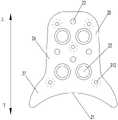
图2示出了图1中的假体本体的正视图;Figure 2 shows a front view of the prosthesis body of Figure 1;
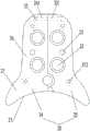
图3示出了图1中的假体本体的侧视图;Figure 3 shows a side view of the prosthesis body of Figure 1;
图4示出了图1中的假体本体的剖视图;Figure 4 shows a cross-sectional view of the prosthesis body in Figure 1;
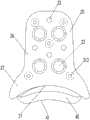
图5示出了根据本发明实施例三提供的髋关节假体的结构示意图;5 shows a schematic structural diagram of a hip joint prosthesis provided according to Embodiment 3 of the present invention;
图6示出了根据本发明实施例三提供的髋关节假体另一状态的结构示意图;6 shows a schematic structural diagram of another state of the hip joint prosthesis provided according to Embodiment 3 of the present invention;
图7示出了根据本发明实施例三提供的髋关节假体的侧视图;Fig. 7 shows the side view of the hip joint prosthesis provided according to the third embodiment of the present invention;
图8示出了根据本发明实施例二提供的髋关节假体的安装示意图;Fig. 8 shows a schematic diagram of the installation of the hip joint prosthesis provided according to the second embodiment of the present invention;
图9示出了图8中的假体本体和内衬的装配示意图;Fig. 9 shows the assembly schematic diagram of the prosthesis body and the inner liner in Fig. 8;
图10示出了图8中的假体本体和内衬的侧视图;Figure 10 shows a side view of the prosthesis body and liner of Figure 8;
图11示出了图8中的假体本体和内衬的剖视图。FIG. 11 shows a cross-sectional view of the prosthesis body and liner of FIG. 8 .
其中,上述附图包括以下附图标记:Wherein, the above-mentioned drawings include the following reference signs:
10、髋骨本体;10. Hip bone body;
20、假体本体;21、第一曲面;22、连接孔;23、第二克氏针孔;24、第一本体;241、第一通孔;242、第一台阶;25、第二本体;251、第二通孔;26、连接段;27、支撑段;20, prosthesis body; 21, first curved surface; 22, connecting hole; 23, second K-wire hole; 24, first body; 241, first through hole; 242, first step; 25, second body ; 251, the second through hole; 26, the connecting section; 27, the support section;
30、连接件;31、固定钉;312、第一克氏针孔;32、紧固件;30. Connecting parts; 31. Fixing nails; 312. The first K-wire hole; 32. Fasteners;
40、内衬;41、第二曲面;40. Inner lining; 41. Second curved surface;
50、卡槽;51、凸台;50, card slot; 51, boss;
60、髋臼。60, acetabulum.
具体实施方式Detailed ways
下面将结合本发明实施例中的附图,对本发明实施例中的技术方案进行清楚、完整地描述,显然,所描述的实施例仅仅是本发明一部分实施例,而不是全部的实施例。以下对至少一个示例性实施例的描述实际上仅仅是说明性的,决不作为对本发明及其应用或使用的任何限制。基于本发明中的实施例,本领域普通技术人员在没有作出创造性劳动前提下所获得的所有其他实施例,都属于本发明保护的范围。The technical solutions in the embodiments of the present invention will be clearly and completely described below with reference to the accompanying drawings in the embodiments of the present invention. Obviously, the described embodiments are only a part of the embodiments of the present invention, but not all of the embodiments. The following description of at least one exemplary embodiment is merely illustrative in nature and is in no way intended to limit the invention, its application, or uses. Based on the embodiments of the present invention, all other embodiments obtained by those of ordinary skill in the art without creative efforts shall fall within the protection scope of the present invention.
如图1至图4所示,本发明实施例一提供了一种髋关节假体,该髋关节假体包括假体本体20和连接件30。假体本体20位于髋臼60的一侧,假体本体20的下端具有与髋臼60的外壁相适配的第一曲面21,假体本体20能够通过第一曲面21与髋臼60的外壁相抵接。连接件30设置于假体本体20,假体本体20通过连接件30与髋骨本体10连接。As shown in FIGS. 1 to 4 , a first embodiment of the present invention provides a hip joint prosthesis, which includes a
应用本实施例提供的髋关节假体,在髋臼60的一侧设置假体本体20,假体本体20的下端具有与髋臼60的外壁相适配的第一曲面21,假体本体20能够通过第一曲面21与髋臼60的外壁相抵接,连接件30设置于假体本体20,通过连接件30将假体本体20与髋骨本体10连接。对于发育性髋关节脱位轻症患者和髋关节病变初期的治疗,采用本发明提供的髋关节假体,利用连接件30将假体本体20安装到髋骨本体10上,假体本体20的第一曲面21抵接髋臼60的外壁,不需要采用人工髋关节置换手术将整个髋臼60替换掉,减轻了对患者的损伤。Using the hip joint prosthesis provided in this embodiment, a
具体地,人工髋关节置换手术为:将假体利用螺钉等连接件安装至患者的骨质上,取代患者的病变关节,进而重建患者的髋关节功能,其中,假体包括股骨假体和髋臼假体。Specifically, the artificial hip replacement surgery is to install a prosthesis on the patient's bone with a screw and other connectors to replace the patient's diseased joint, thereby reconstructing the patient's hip joint function, wherein the prosthesis includes a femoral prosthesis and a hip joint. Abutment prosthesis.
在本实施例中,假体本体20的下端为图2中的下端,仅是便于进行理解。具体地,假体本体20的下端为假体本体20的靠近髋臼60的一端。In this embodiment, the lower end of the
具体地,假体本体20采用电子束熔化成型技术(Electron Beam Melting)3D打印技术一体成型。Specifically, the
如图2所示,连接件30包括螺钉,假体本体20设置有连接孔22,螺钉穿设于连接孔22并与髋骨本体10连接。采用上述连接结构,具有连接结构简单,便于装配的优点。As shown in FIG. 2 , the connecting member 30 includes a screw, the
在本实施例中,连接孔22为多个且具有台阶,便于螺钉的螺帽埋入假体本体20中,避免螺钉的螺帽与人体的骨骼或组织发生干涉摩擦。In this embodiment, the connecting
如图3所示,连接件30还包括固定钉31,固定钉31设置在假体本体20的朝向髋骨本体10的一侧,固定钉31的表面设置有第一多孔结构。采用固定钉31并在固定钉31的表面设置有第一多孔结构,便于骨组织的长入,进而可以实现对髋关节假体的远期固定。As shown in FIG. 3 , the connector 30 further includes a
在本实施例中,固定钉31的表面为类骨小梁型多孔结构,孔隙率为50%~80%,孔径为800μm±200μm。In this embodiment, the surface of the
其中,第一多孔结构的孔隙率可以为50%、60%、70%、80%以及50%至80%之间的任一值。第一多孔结构的孔径可以为600μm、700μm、800μm、900μm、1000μm以及600μm至1000μm之间的任一值。The porosity of the first porous structure may be 50%, 60%, 70%, 80%, and any value between 50% and 80%. The pore size of the first porous structure may be any value between 600 μm, 700 μm, 800 μm, 900 μm, 1000 μm, and 600 μm to 1000 μm.
如图3和图4所示,固定钉31具有第一克氏针孔312,第一克氏针孔312沿固定钉31的轴向延伸并贯穿固定钉31设置。采用上述结构,在第一克氏针孔312中插入克氏针,便于利用克氏针测量患者残骨的厚度,进而确定固定钉31的长度。As shown in FIGS. 3 and 4 , the fixing
如图2所示,假体本体20具有贯穿设置的第二克氏针孔23。通过在第二克氏针孔23中插入克氏针,可以实现对髋关节假体的临时固定。As shown in FIG. 2 , the
在本实施例中,螺钉、第一克氏针孔312以及第二克氏针孔23间隔布置。In this embodiment, the screw, the first K-
如图2所示,假体本体20包括连接段26以及位于连接段26的下方的支撑段27,第一曲面21设置在支撑段27的下端,支撑段27的尺寸在由上至下的方向上逐渐增大,采用上述尺寸设置,可以使假体本体20的外形与患者的髋骨本体相适配,提升患者的使用感受。As shown in FIG. 2 , the
具体地,由于支撑段27的尺寸在由上至下的方向上逐渐增大,支撑段27与髋臼60具有足够大的接触面积,进而能够利用支撑段27对髋臼60进行有效及稳固的支撑。Specifically, since the size of the
其中,假体本体20的与髋骨本体10连接的一侧设置有第二多孔结构。第二多孔结构有利于骨组织的长入,便于髋关节假体与患者骨质的结合。Wherein, the side of the
在本实施例中,第二多孔结构孔隙率为类骨小梁型多孔结构,50%~80%,孔径为800μm±200μm。In this embodiment, the porosity of the second porous structure is a trabecular bone-like porous structure, ranging from 50% to 80%, and the pore diameter is 800 μm±200 μm.
其中,第二多孔结构的孔隙率可以为50%、60%、70%、80%以及50%至80%之间的任一值。第二多孔结构的孔径可以为600μm、700μm、800μm、900μm、1000μm以及600μm至1000μm之间的任一值。The porosity of the second porous structure may be 50%, 60%, 70%, 80%, and any value between 50% and 80%. The pore size of the second porous structure may be any value between 600 μm, 700 μm, 800 μm, 900 μm, 1000 μm, and 600 μm to 1000 μm.
需要说明的是,本实施例提供的髋关节假体可植入到患者的髂骨翼、坐骨支和耻骨支等部位。It should be noted that the hip joint prosthesis provided in this embodiment can be implanted into the patient's iliac wing, ischial ramus, and pubic ramus.
如图8至图11所示,本发明实施例二提供了一种髋关节假体,实施例二与实施例一的区别在于,在实施例二中,髋关节假体还包括内衬40。As shown in FIGS. 8 to 11 , the second embodiment of the present invention provides a hip joint prosthesis. The difference between the second embodiment and the first embodiment is that in the second embodiment, the hip joint prosthesis further includes an
具体地,内衬40设置在假体本体20的下端,内衬40的下端具有与髋臼60的外壁相适配的第二曲面41,假体本体20能够通过第二曲面41与髋臼60的外壁相抵接。采用内衬40设置在假体本体20的下端,当患者的髋骨本体受损严重时,可以利用内衬40的第二曲面41与髋臼60的外壁相抵接,可以进一步增大髋关节假体的使用范围。Specifically, the
其中,内衬40采用聚乙烯等医用耐磨材料制作。The
在本实施例中,内衬40设计有不同的厚度和不同形式的第二曲面41,方便术中选择。In this embodiment, the
如图11所示,内衬40的上端设置有卡槽50,假体本体20的下端设置有与卡槽50卡接配合的凸台51。或者,内衬40的上端设置有凸台51,假体本体20的下端设置有与凸台51卡接配合的卡槽50。通过设置卡槽50与凸台51相卡接配合的方式,能够将内衬40与假体本体20连接并进行限位。As shown in FIG. 11 , the upper end of the
在本实施例中,内衬40的上端设置有卡槽50,假体本体20的下端设置有与卡槽50卡接配合的凸台51,且卡槽50为燕尾槽,凸台51的形状尺寸与卡槽50的形状尺寸相适配。In this embodiment, the upper end of the
如图5至图7所示,本发明实施例三提供了一种髋关节假体,实施例三与实施例一的区别在于,在实施例三中,假体本体20包括可相对移动的第一本体24和第二本体25。As shown in FIGS. 5 to 7 , Embodiment 3 of the present invention provides a hip joint prosthesis. The difference between Embodiment 3 and Embodiment 1 is that in Embodiment 3, the
其中,第一本体24的下端与第二本体25的下端相铰接,第一本体24的上端与第二本体25的上端连接。或者,第一本体24的上端与第二本体25的上端相铰接,第一本体24的下端与第二本体25的下端连接。通过将假体本体20设置为第一本体24和第二本体25,并采用铰接的方式连接,当患者的髋骨本体产生骨折或骨裂时,便于利用利用第一本体24和第二本体25将患者的骨折或骨裂部位进行紧密的连接,加快骨质的愈合。The lower end of the
如图5所示,第一本体24的上端设置有第一通孔241,第二本体25的上端设置有第二通孔251,髋关节假体还包括紧固件32,第一本体24和第二本体25通过紧固件32穿设于第一通孔241和第二通孔251连接。采用紧固件32连接第一本体24和第二本体25,具有便于装配的优点。As shown in FIG. 5 , the upper end of the
在本实施例中,第一本体24的靠近第二本体25的一侧设置有第一台阶242,第二本体25具有对应第一台阶242设置的第二台阶,第一台阶242和第二台阶均沿假体本体20的上下方向延伸,第一台阶242和第二台阶插接配合。采用上述结构,便于利用第一台阶242和第二台阶对第一本体24和第二本体25进行限位,使第一本体24和第二本体25不会产生错位。In this embodiment, a
需要说明的是,第一台阶242和第二台阶插接配合,指的是第一台阶242的水平台阶面和第二台阶的水平台阶面相抵接,第一台阶242的竖直台阶面和第二台阶的竖直台阶面相抵接。It should be noted that the plug-fit of the
通过实施例提供的髋关节假体,具有以下有益效果:The hip joint prosthesis provided by the embodiment has the following beneficial effects:
(1)采用本发明提供的髋关节假体,利用连接件30将假体本体20安装到髋骨本体10上,假体本体20的第一曲面21抵接髋臼60的外壁,不需要采用人工髋关节置换手术将整个髋臼60替换掉,减轻了对患者的损伤;(1) Using the hip joint prosthesis provided by the present invention, the
(2)采用固定钉31并在固定钉31的表面设置有第一多孔结构,便于骨组织的长入,进而可以实现对髋关节假体的远期固定;(2) The
(3)固定钉31具有第一克氏针孔312,在第一克氏针孔312中插入克氏针,便于利用克氏针测量患者残骨的厚度,进而确定固定钉31的长度;(3) The
(4)在第二克氏针孔23中插入克氏针,可以实现对髋关节假体的临时固定;(4) Inserting a Kirschner wire into the second
(5)采用内衬40设置在假体本体20的下端,当患者的髋骨本体受损严重时,可以利用内衬40的第二曲面41与髋臼60的外壁相抵接,可以进一步增大髋关节假体的使用范围;(5) The
(6)通过将假体本体20设置为第一本体24和第二本体25,并采用铰接的方式连接,当患者的髋骨本体产生骨折或骨裂时,便于利用利用第一本体24和第二本体25将患者的骨折或骨裂部位进行紧密的连接,加快骨质的愈合。(6) By setting the
需要注意的是,这里所使用的术语仅是为了描述具体实施方式,而非意图限制根据本申请的示例性实施方式。如在这里所使用的,除非上下文另外明确指出,否则单数形式也意图包括复数形式,此外,还应当理解的是,当在本说明书中使用术语“包含”和/或“包括”时,其指明存在特征、步骤、操作、器件、组件和/或它们的组合。It should be noted that the terminology used herein is for the purpose of describing specific embodiments only, and is not intended to limit the exemplary embodiments according to the present application. As used herein, unless the context clearly dictates otherwise, the singular is intended to include the plural as well, furthermore, it is to be understood that when the terms "comprising" and/or "including" are used in this specification, it indicates that There are features, steps, operations, devices, components and/or combinations thereof.
除非另外具体说明,否则在这些实施例中阐述的部件和步骤的相对布置、数字表达式和数值不限制本发明的范围。同时,应当明白,为了便于描述,附图中所示出的各个部分的尺寸并不是按照实际的比例关系绘制的。对于相关领域普通技术人员已知的技术、方法和设备可能不作详细讨论,但在适当情况下,所述技术、方法和设备应当被视为说明书的一部分。在这里示出和讨论的所有示例中,任何具体值应被解释为仅仅是示例性的,而不是作为限制。因此,示例性实施例的其它示例可以具有不同的值。应注意到:相似的标号和字母在下面的附图中表示类似项,因此,一旦某一项在一个附图中被定义,则在随后的附图中不需要对其进行进一步讨论。The relative arrangement of the components and steps, the numerical expressions and numerical values set forth in these embodiments do not limit the scope of the invention unless specifically stated otherwise. Meanwhile, it should be understood that, for the convenience of description, the dimensions of various parts shown in the accompanying drawings are not drawn in an actual proportional relationship. Techniques, methods, and apparatus known to those of ordinary skill in the relevant art may not be discussed in detail, but where appropriate, such techniques, methods, and apparatus should be considered part of the specification. In all examples shown and discussed herein, any specific value should be construed as illustrative only and not as limiting. Accordingly, other examples of exemplary embodiments may have different values. It should be noted that like numerals and letters refer to like items in the following figures, so once an item is defined in one figure, it does not require further discussion in subsequent figures.
在本发明的描述中,需要理解的是,方位词如“前、后、上、下、左、右”、“横向、竖向、垂直、水平”和“顶、底”等所指示的方位或位置关系通常是基于附图所示的方位或位置关系,仅是为了便于描述本发明和简化描述,在未作相反说明的情况下,这些方位词并不指示和暗示所指的装置或元件必须具有特定的方位或者以特定的方位构造和操作,因此不能理解为对本发明保护范围的限制;方位词“内、外”是指相对于各部件本身的轮廓的内外。In the description of the present invention, it should be understood that the orientations indicated by orientation words such as "front, rear, top, bottom, left, right", "horizontal, vertical, vertical, horizontal" and "top, bottom" etc. Or the positional relationship is usually based on the orientation or positional relationship shown in the drawings, which is only for the convenience of describing the present invention and simplifying the description, and these orientation words do not indicate or imply the indicated device or element unless otherwise stated. It must have a specific orientation or be constructed and operated in a specific orientation, so it cannot be construed as a limitation on the protection scope of the present invention; the orientation words "inside and outside" refer to the inside and outside relative to the outline of each component itself.
为了便于描述,在这里可以使用空间相对术语,如“在……之上”、“在……上方”、“在……上表面”、“上面的”等,用来描述如在图中所示的一个器件或特征与其他器件或特征的空间位置关系。应当理解的是,空间相对术语旨在包含除了器件在图中所描述的方位之外的在使用或操作中的不同方位。例如,如果附图中的器件被倒置,则描述为“在其他器件或构造上方”或“在其他器件或构造之上”的器件之后将被定位为“在其他器件或构造下方”或“在其他器件或构造之下”。因而,示例性术语“在……上方”可以包括“在……上方”和“在……下方”两种方位。该器件也可以其他不同方式定位(旋转90度或处于其他方位),并且对这里所使用的空间相对描述作出相应解释。For ease of description, spatially relative terms, such as "on", "over", "on the surface", "above", etc., may be used herein to describe what is shown in the figures. The spatial positional relationship of one device or feature shown to other devices or features. It should be understood that spatially relative terms are intended to encompass different orientations of the device in use or operation in addition to the orientation depicted in the figures. For example, if the device in the figures is turned over, elements described as "above" or "over" other devices or features would then be oriented "below" or "over" the other devices or features under other devices or constructions". Thus, the exemplary term "above" can encompass both an orientation of "above" and "below." The device may also be otherwise oriented (rotated 90 degrees or at other orientations) and the spatially relative descriptions used herein interpreted accordingly.
此外,需要说明的是,使用“第一”、“第二”等词语来限定零部件,仅仅是为了便于对相应零部件进行区别,如没有另行声明,上述词语并没有特殊含义,因此不能理解为对本发明保护范围的限制。In addition, it should be noted that the use of words such as "first" and "second" to define components is only for the convenience of distinguishing corresponding components. Unless otherwise stated, the above words have no special meaning and therefore cannot be understood to limit the scope of protection of the present invention.
以上所述仅为本发明的优选实施例而已,并不用于限制本发明,对于本领域的技术人员来说,本发明可以有各种更改和变化。凡在本发明的精神和原则之内,所作的任何修改、等同替换、改进等,均应包含在本发明的保护范围之内。The above descriptions are only preferred embodiments of the present invention, and are not intended to limit the present invention. For those skilled in the art, the present invention may have various modifications and changes. Any modification, equivalent replacement, improvement, etc. made within the spirit and principle of the present invention shall be included within the protection scope of the present invention.
Claims (9)
Translated fromChinesePriority Applications (1)
| Application Number | Priority Date | Filing Date | Title |
|---|---|---|---|
| CN202111302967.1ACN113730044B (en) | 2021-11-05 | 2021-11-05 | Hip joint prosthesis |
Applications Claiming Priority (1)
| Application Number | Priority Date | Filing Date | Title |
|---|---|---|---|
| CN202111302967.1ACN113730044B (en) | 2021-11-05 | 2021-11-05 | Hip joint prosthesis |
Publications (2)
| Publication Number | Publication Date |
|---|---|
| CN113730044A CN113730044A (en) | 2021-12-03 |
| CN113730044Btrue CN113730044B (en) | 2022-04-12 |
Family
ID=78727367
Family Applications (1)
| Application Number | Title | Priority Date | Filing Date |
|---|---|---|---|
| CN202111302967.1AActiveCN113730044B (en) | 2021-11-05 | 2021-11-05 | Hip joint prosthesis |
Country Status (1)
| Country | Link |
|---|---|
| CN (1) | CN113730044B (en) |
Families Citing this family (1)
| Publication number | Priority date | Publication date | Assignee | Title |
|---|---|---|---|---|
| CN118892385B (en)* | 2024-10-08 | 2025-03-11 | 北京爱康宜诚医疗器材有限公司 | Acetabular prosthesis |
Family Cites Families (6)
| Publication number | Priority date | Publication date | Assignee | Title |
|---|---|---|---|---|
| CN203483545U (en)* | 2013-10-12 | 2014-03-19 | 史振满 | Improved artificial full-hip supporting joint |
| US12127942B2 (en)* | 2017-05-31 | 2024-10-29 | Zimmer, Inc. | Customizable augments and methods for acetabular implants |
| CA3061359A1 (en)* | 2017-06-08 | 2018-12-13 | Skeletal Dynamics, Llc | Articulated fracture fixation plate assembly and method of use |
| CN108938149B (en)* | 2018-09-13 | 2023-07-28 | 北京爱康宜诚医疗器材有限公司 | Bone block is filled to pestle and mortar joint |
| CN111658237B (en)* | 2020-06-28 | 2023-07-21 | 中国人民解放军空军军医大学 | A 3D printed titanium alloy hemi-pelvic prosthesis with partial acetabular retention |
| CN112107395B (en)* | 2020-10-15 | 2025-07-22 | 北京积水潭医院 | Biological type acetabulum partial reconstruction prosthesis for treating hip joint dysplasia |
- 2021
- 2021-11-05CNCN202111302967.1Apatent/CN113730044B/enactiveActive
Also Published As
| Publication number | Publication date |
|---|---|
| CN113730044A (en) | 2021-12-03 |
Similar Documents
| Publication | Publication Date | Title |
|---|---|---|
| US20210393412A1 (en) | Orthopedic augments having recessed pockets | |
| USRE36758E (en) | Artificial facet joint | |
| JP3130533B2 (en) | Joint prosthesis | |
| JP4152452B2 (en) | Prosthesis mounting device | |
| JP2009513285A (en) | Bone fixation device and method | |
| JP6554166B2 (en) | Osseo Integration-capable device | |
| BRPI0618305A2 (en) | mounting system and method for increasing implant fixation to bone | |
| KR20140019764A (en) | Implant components and methods | |
| CN104042363A (en) | Orthopaedic Tibial Prosthesis Having Tibial Augments | |
| JPH05192350A (en) | Internal prothesis for hipbone | |
| CN107496061A (en) | A kind of assembly type artificial crystalline lens | |
| CN113730044B (en) | Hip joint prosthesis | |
| US7547328B2 (en) | Canine femoral stem system | |
| CN110368139A (en) | Prosthetic appliance | |
| CN115813614B (en) | Long bone diaphysis prosthetic components | |
| CN117122452A (en) | Acetabular prosthesis | |
| CN113749827B (en) | Acetabular prosthesis | |
| JP4347813B2 (en) | Hip prosthesis with trunk inserted into the femur | |
| CN205007076U (en) | Artificial vertebral lamina | |
| CN115624418A (en) | Tibia support prosthesis | |
| CN112386374B (en) | Intramedullary fusion device and femoral prosthesis component with same | |
| CN211560553U (en) | Dentata prosthesis | |
| CN109528360B (en) | Acetabular cup supporting device | |
| CN211156488U (en) | Unicondylar prosthesis | |
| CN220069930U (en) | Integrated acetabular prosthesis and artificial hip joint with same |
Legal Events
| Date | Code | Title | Description |
|---|---|---|---|
| PB01 | Publication | ||
| PB01 | Publication | ||
| SE01 | Entry into force of request for substantive examination | ||
| SE01 | Entry into force of request for substantive examination | ||
| GR01 | Patent grant | ||
| GR01 | Patent grant |