CN113719256B - Variable-diameter ball seat well cementation sliding sleeve for infinite-stage fracturing of horizontal well - Google Patents
Variable-diameter ball seat well cementation sliding sleeve for infinite-stage fracturing of horizontal wellDownload PDFInfo
- Publication number
- CN113719256B CN113719256BCN202111095080.XACN202111095080ACN113719256BCN 113719256 BCN113719256 BCN 113719256BCN 202111095080 ACN202111095080 ACN 202111095080ACN 113719256 BCN113719256 BCN 113719256B
- Authority
- CN
- China
- Prior art keywords
- sliding sleeve
- piston
- fracturing
- ball seat
- pin
- Prior art date
- Legal status (The legal status is an assumption and is not a legal conclusion. Google has not performed a legal analysis and makes no representation as to the accuracy of the status listed.)
- Active
Links
- 238000009434installationMethods0.000claimsabstractdescription9
- 230000000712assemblyEffects0.000claimsabstractdescription3
- 238000000429assemblyMethods0.000claimsabstractdescription3
- 238000007789sealingMethods0.000claimsdescription5
- 238000000034methodMethods0.000abstractdescription8
- 230000009471actionEffects0.000description13
- 230000008569processEffects0.000description5
- 239000007788liquidSubstances0.000description4
- 238000005516engineering processMethods0.000description3
- 230000007246mechanismEffects0.000description3
- 229910000639Spring steelInorganic materials0.000description2
- 230000015572biosynthetic processEffects0.000description2
- 230000004048modificationEffects0.000description2
- 238000012986modificationMethods0.000description2
- 230000009286beneficial effectEffects0.000description1
- 230000000903blocking effectEffects0.000description1
- 230000008859changeEffects0.000description1
- 238000010276constructionMethods0.000description1
- 230000007423decreaseEffects0.000description1
- 230000007812deficiencyEffects0.000description1
- 238000010586diagramMethods0.000description1
- 238000006073displacement reactionMethods0.000description1
- 230000000694effectsEffects0.000description1
- 230000035699permeabilityEffects0.000description1
- 239000011435rockSubstances0.000description1
- 230000001568sexual effectEffects0.000description1
- 239000003079shale oilSubstances0.000description1
- 238000010008shearingMethods0.000description1
- 230000003068static effectEffects0.000description1
- 230000000638stimulationEffects0.000description1
- XLYOFNOQVPJJNP-UHFFFAOYSA-NwaterSubstancesOXLYOFNOQVPJJNP-UHFFFAOYSA-N0.000description1
Images


Classifications
- E—FIXED CONSTRUCTIONS
- E21—EARTH OR ROCK DRILLING; MINING
- E21B—EARTH OR ROCK DRILLING; OBTAINING OIL, GAS, WATER, SOLUBLE OR MELTABLE MATERIALS OR A SLURRY OF MINERALS FROM WELLS
- E21B34/00—Valve arrangements for boreholes or wells
- E21B34/06—Valve arrangements for boreholes or wells in wells
- E21B34/14—Valve arrangements for boreholes or wells in wells operated by movement of tools, e.g. sleeve valves operated by pistons or wire line tools
- E—FIXED CONSTRUCTIONS
- E21—EARTH OR ROCK DRILLING; MINING
- E21B—EARTH OR ROCK DRILLING; OBTAINING OIL, GAS, WATER, SOLUBLE OR MELTABLE MATERIALS OR A SLURRY OF MINERALS FROM WELLS
- E21B43/00—Methods or apparatus for obtaining oil, gas, water, soluble or meltable materials or a slurry of minerals from wells
- E21B43/25—Methods for stimulating production
- E21B43/26—Methods for stimulating production by forming crevices or fractures
- Y—GENERAL TAGGING OF NEW TECHNOLOGICAL DEVELOPMENTS; GENERAL TAGGING OF CROSS-SECTIONAL TECHNOLOGIES SPANNING OVER SEVERAL SECTIONS OF THE IPC; TECHNICAL SUBJECTS COVERED BY FORMER USPC CROSS-REFERENCE ART COLLECTIONS [XRACs] AND DIGESTS
- Y02—TECHNOLOGIES OR APPLICATIONS FOR MITIGATION OR ADAPTATION AGAINST CLIMATE CHANGE
- Y02E—REDUCTION OF GREENHOUSE GAS [GHG] EMISSIONS, RELATED TO ENERGY GENERATION, TRANSMISSION OR DISTRIBUTION
- Y02E10/00—Energy generation through renewable energy sources
- Y02E10/10—Geothermal energy
Landscapes
- Life Sciences & Earth Sciences (AREA)
- Engineering & Computer Science (AREA)
- Geology (AREA)
- Mining & Mineral Resources (AREA)
- Physics & Mathematics (AREA)
- Environmental & Geological Engineering (AREA)
- Fluid Mechanics (AREA)
- General Life Sciences & Earth Sciences (AREA)
- Geochemistry & Mineralogy (AREA)
- Actuator (AREA)
Abstract
Translated fromChinese
Description
Translated fromChinese技术领域technical field
本发明涉及用于水平井无限级压裂的可变径球座固井滑套,属于石油天然气开采井下工具技术领域。The invention relates to a variable-diameter spherical seat cementing sliding sleeve used for infinite-stage fracturing of horizontal wells, and belongs to the technical field of downhole tools for oil and gas exploitation.
背景技术Background technique
页岩油气、致密砂岩油气等非常规油气储层由于岩石致密、孔隙度、渗透率极低,流动阻力大,单井产能低,稳产时间短,产量下降快。水平井分段压裂工艺改造储层,井眼穿过的油层长度大,与油层表面接触面积大,同时能够有效沟通缝隙,增大泄油面积以及裂缝导流能力,实现增产改造。套管固井滑套作为新兴水平井分段压裂技术,其井眼适应性强,满足大规模,大排量的压裂需要。Unconventional oil and gas reservoirs such as shale oil and gas and tight sandstone oil and gas have tight rocks, extremely low porosity and permeability, and high flow resistance, resulting in low single well productivity, short stable production time, and rapid production decline. The staged fracturing process of horizontal wells transforms reservoirs. The wellbore penetrates a long oil layer and has a large contact area with the oil layer surface. At the same time, it can effectively communicate with gaps, increase oil drainage area and fracture conductivity, and realize production stimulation. As a new staged fracturing technology for horizontal wells, casing cementing sliding sleeve has strong wellbore adaptability and meets the needs of large-scale and large-displacement fracturing.
目前国内采用的固井滑套技术主要是投球打开式压裂滑套,利用滑套工具分割井筒,进行一段一簇压裂。投球滑套通过从井口依次投入尺寸由小到大的憋压球,当憋压球到达滑套位置,与滑套内球座形成密封,向管串内打压进行憋压,使滑套上固定的剪钉断裂,滑套下行使压裂通道打开,向地层开始压裂。由于投球滑套采用投球剪断破坏销钉的形式打开,一般需要下入工具实现滑套关闭;且压裂通道关闭后无法二次启闭,中后期无法找堵水作业;其次采用下行打开滑套的方式,固井胶塞通过时时存在提前打开滑套的风险;此外由于压裂球尺寸限制,压裂级数受限,压裂过程中只能顺序压裂,无法根据压裂工艺的需要进行选择性压裂。At present, the cementing sliding sleeve technology used in China is mainly the ball-throwing open fracturing sliding sleeve, which uses the sliding sleeve tool to divide the wellbore and perform cluster-by-section fracturing. The ball-throwing sleeve is put into the pressure-suppressing balls from small to large in order from the wellhead. When the pressure-suppressing ball reaches the position of the sliding sleeve, it forms a seal with the inner ball seat of the sliding sleeve, pressurizes the pipe string to hold the pressure, and fixes the sliding sleeve. When the shear pin breaks, the sliding sleeve moves down to open the fracturing channel and start fracturing the formation. Since the ball-throwing sliding sleeve is opened by throwing the ball and shearing the broken pin, it is generally necessary to run in a tool to close the sliding sleeve; and after the fracturing channel is closed, it cannot be opened and closed again, and water blocking operations cannot be found in the middle and late stages; secondly, the sliding sleeve is opened downward. There is a risk of opening the sliding sleeve in advance when the cementing plug passes through; in addition, due to the size limitation of the fracturing ball, the number of fracturing stages is limited, and the fracturing process can only be fracturing sequentially, and cannot be selected according to the needs of the fracturing process. Sexual fracturing.
发明内容Contents of the invention
本发明主要是克服现有技术中的不足之处,提出一种用于水平井无限级压裂的可变径球座固井滑套,本发明通过控制电磁阀的动作实现液压通道的启闭,从而传压给活塞,活塞沿径向运动,内径收缩形成球座,从地面投入压裂球使其与球座接触密封,管内憋压打开滑套;压裂结束后,通过解除滑套的锁定,滑套在弹簧钢作用下复位,实现滑套关闭。The present invention mainly overcomes the deficiencies in the prior art, and proposes a variable-diameter ball-seat cementing sliding sleeve for infinite-stage fracturing of horizontal wells. The present invention realizes the opening and closing of the hydraulic channel by controlling the action of the solenoid valve , so that the pressure is transmitted to the piston, the piston moves radially, the inner diameter shrinks to form a ball seat, and the fracturing ball is put into the ball seat from the ground to make it contact and seal with the ball seat, and the pressure in the tube is suppressed to open the sliding sleeve; after the fracturing is completed, by releasing the sliding sleeve Locked, the sliding sleeve resets under the action of spring steel to realize the closing of the sliding sleeve.
本发明解决上述技术问题所提供的技术方案是:用于水平井无限级压裂的可变径球座固井滑套,包括上接头、外套管、内滑套、下接头,所述外套管上设有压裂孔眼,所述内滑套上设有弹簧,用于内滑套在外套管内复位,所述外套管上设有回油通道、进油通道、销钉控制油路通道以及与销钉控制油路通道的销钉安装内盲孔,所述销钉安装内盲孔内设有限位销钉、复位弹簧Ⅰ,所述复位弹簧Ⅰ两端分别固定在限位销钉的上端、销钉安装内盲孔的内壁上;The technical solution provided by the present invention to solve the above-mentioned technical problems is: a variable-diameter ball seat cementing sliding sleeve for infinite stage fracturing in horizontal wells, including an upper joint, an outer casing, an inner sliding sleeve, and a lower joint. There are fracturing holes on the inner sliding sleeve, and a spring is provided on the inner sliding sleeve to reset the inner sliding sleeve in the outer sleeve. The outer sleeve is provided with an oil return channel, an oil inlet channel, a pin control oil channel, and a pin The pin for controlling the oil passage is installed in an inner blind hole, and the inner blind hole for the pin is installed with a limit pin and a return spring I. on the inner wall;
所述内滑套上设有限位销钉孔、两个相对设置的球座组件以及安装球座组件的腔体,所述球座组件包括活塞以及固定在活塞上的半圆环,两个半圆环在内滑套内相对布置形成球座,用于拦截压裂球;所述活塞与腔体之间具有活塞上腔、活塞下腔;所述内滑套内还设有与活塞下腔连通的回油孔,所述回油孔与回油通道连通。The inner sliding sleeve is provided with a limit pin hole, two oppositely arranged ball seat assemblies and a cavity for installing the ball seat assembly. The ball seat assembly includes a piston and a semicircular ring fixed on the piston. The two semicircular The rings are relatively arranged in the inner sliding sleeve to form a ball seat, which is used to intercept the fracturing ball; there is an upper piston chamber and a lower piston chamber between the piston and the cavity; The oil return hole communicates with the oil return passage.
进一步的技术方案是,所述球座组件还包括支撑组件,所述支撑组件包括电机、电机电源、丝杆转轴、螺母,所述丝杆转轴的一端与电机的转轴连接,另一端与螺母螺纹连接,所述螺母位于活塞的上方,所述电机电源与电机电连接。A further technical solution is that the ball seat assembly also includes a support assembly, the support assembly includes a motor, a motor power supply, a screw shaft, and a nut, one end of the screw shaft is connected to the shaft of the motor, and the other end is threaded with the nut. connected, the nut is located above the piston, and the motor power supply is electrically connected to the motor.
进一步的技术方案是,所述活塞下腔内设有用于活塞复位的复位弹簧Ⅱ。A further technical solution is that a reset spring II for the piston to reset is provided in the lower cavity of the piston.
进一步的技术方案是,所述外套管上设有电源线路、单片机、控制器。A further technical solution is that a power line, a single-chip microcomputer, and a controller are provided on the outer casing.
进一步的技术方案是,所述进油通道、回油孔、销钉控制油路通道内分别设有电磁阀Ⅰ、电磁阀Ⅱ、电磁阀Ⅲ。A further technical solution is that solenoid valve I, solenoid valve II, and solenoid valve III are respectively arranged in the oil inlet channel, oil return hole, and pin control oil channel.
进一步的技术方案是,所述外套管上设有红外测距传感器,所述内滑套的外壁上设有多个线性圆孔槽,所述红外测距传感器监测多个线性圆孔槽的孔深。A further technical solution is that the outer sleeve is provided with an infrared ranging sensor, and the outer wall of the inner sliding sleeve is provided with a plurality of linear circular hole slots, and the infrared ranging sensor monitors the holes of the plurality of linear circular hole slots. deep.
进一步的技术方案是,所述内滑套两端均设有密封圈。A further technical solution is that both ends of the inner sliding sleeve are provided with sealing rings.
本发明具有以下有益效果:The present invention has the following beneficial effects:
1、采用可变径球座方式,无需下入工具,投球憋压即可实现滑套的开启,井内全通径,压裂级数不受限制。1. Adopt variable diameter ball seat method, no need to run in the tool, the sliding sleeve can be opened by throwing the ball to suppress the pressure, the full diameter in the well, and the number of fracturing stages is not limited.
2、采用电磁阀动作控制活塞启动压力通道的启闭,液压控制球座的形成,控制系统结构简易,同时根据压裂工艺的需要通过系统控制某位置滑套开启进行选择性压裂。2. The solenoid valve action is used to control the opening and closing of the piston starting pressure channel, and the hydraulic pressure controls the formation of the ball seat. The structure of the control system is simple. At the same time, according to the needs of the fracturing process, the system controls the opening of a certain position of the sliding sleeve to perform selective fracturing.
3、球座上行与下行到位后,采用电机驱动丝杠机构,丝杠机构轴向直线运动支承球座,使球座固定,滑套运动过程中与液压系统相互独立,互不干涉。3. After the ball seat goes up and down, the motor is used to drive the screw mechanism. The screw mechanism moves axially and linearly to support the ball seat, so that the ball seat is fixed. During the movement of the sliding sleeve, it is independent of the hydraulic system and does not interfere with each other.
4、采用红外测距传感器+单片机控制技术,红外测距传感器通过检测孔深,识别孔深的每一次深度变化,输出一个信号传递给单片机使其不断计数,计数溢出,输出信号传递给控制器控制定位销钉动作,实现滑套的锁定。4. Using infrared ranging sensor + single-chip microcomputer control technology, the infrared ranging sensor detects the depth of the hole, identifies each depth change of the hole depth, and outputs a signal to the single-chip microcomputer to make it count continuously. When the count overflows, the output signal is passed to the controller Control the movement of the positioning pin to realize the locking of the sliding sleeve.
5、高强度,高韧性弹簧可在滑套锁定解除后,利用自身的弹力进行复位,可快速实现滑套的关闭。5. The high-strength, high-tenacity spring can be reset by its own elastic force after the sliding sleeve is locked, and the sliding sleeve can be quickly closed.
附图说明Description of drawings
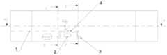
图1为本发明的示意图;Fig. 1 is a schematic diagram of the present invention;
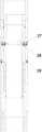
图2为外套管和内套管的左视图;Fig. 2 is the left side view of outer casing and inner casing;
图3为图1中A-A截面剖视图;Fig. 3 is A-A sectional view in Fig. 1;
图4为图2中B-B截面剖视图;Fig. 4 is B-B sectional view in Fig. 2;
图5为图1中C-C截面剖视图(滑套关闭时);Fig. 5 is a cross-sectional view of C-C in Fig. 1 (when the sliding sleeve is closed);
图6为图5中D-D截面剖视图;Fig. 6 is a D-D sectional view in Fig. 5;
图7为图2中E-E截面剖视图;Fig. 7 is E-E sectional view in Fig. 2;
图8为图1中A-A截面剖视图(滑套打开时);Fig. 8 is a sectional view of section A-A in Fig. 1 (when the sliding sleeve is opened);
图9为图1中F-F截面剖视图(滑套打开时)。Fig. 9 is a cross-sectional view of F-F in Fig. 1 (when the sliding sleeve is opened).
图中所示:1-电源线路,2-单片机,3-盖板,4-控制器,5-回油通道,6-进油通道,7-销钉控制油路,8-上接头,9-限位销钉孔,10-外套管,11-限位销钉,12-下接头,13-半圆环,14-活塞,15-销钉,16-螺母,17-丝杠,18-电池电源,19-电机,20-压裂孔眼,21-滑套,22-弹簧钢,23-密封圈,25-活塞上腔,26-活塞下腔,27-电磁阀Ⅰ,28-电磁阀Ⅱ,29-电磁阀Ⅲ,30-线性圆孔槽,31-红外测距传感器。As shown in the figure: 1-power supply circuit, 2-single chip microcomputer, 3-cover plate, 4-controller, 5-oil return channel, 6-oil inlet channel, 7-pin control oil circuit, 8-upper joint, 9- Limit pin hole, 10-outer sleeve, 11-limit pin, 12-lower connector, 13-semi-circular ring, 14-piston, 15-pin, 16-nut, 17-leading screw, 18-battery power supply, 19 -motor, 20-fracturing hole, 21-sliding sleeve, 22-spring steel, 23-sealing ring, 25-piston upper chamber, 26-piston lower chamber, 27-solenoid valve Ⅰ, 28-solenoid valve Ⅱ, 29- Solenoid valve III, 30-linear circular hole slot, 31-infrared distance measuring sensor.
具体实施方式Detailed ways
下面将结合附图对本发明的技术方案进行清楚、完整地描述,显然,所描述的实施例是本发明一部分实施例,而不是全部的实施例。基于本发明中的实施例,本领域普通技术人员在没有做出创造性劳动前提下所获得的所有其他实施例,都属于本发明保护的范围。The technical solutions of the present invention will be clearly and completely described below in conjunction with the accompanying drawings. Apparently, the described embodiments are some of the embodiments of the present invention, but not all of them. Based on the embodiments of the present invention, all other embodiments obtained by persons of ordinary skill in the art without making creative efforts belong to the protection scope of the present invention.
在本发明的描述中,需要说明的是,术语“中心”、“上”、“下”、“左”、“右”、“竖直”、“水平”、“内”、“外”等指示的方位或位置关系为基于附图所示的方位或位置关系,仅是为了便于描述本发明和简化描述,而不是指示或暗示所指的装置或元件必须具有特定的方位、以特定的方位构造和操作,因此不能理解为对本发明的限制。此外,术语“第一”、“第二”、“第三”仅用于描述目的,而不能理解为指示或暗示相对重要性。In the description of the present invention, it should be noted that the terms "center", "upper", "lower", "left", "right", "vertical", "horizontal", "inner", "outer" etc. The indicated orientation or positional relationship is based on the orientation or positional relationship shown in the drawings, and is only for the convenience of describing the present invention and simplifying the description, rather than indicating or implying that the referred device or element must have a specific orientation, or in a specific orientation. construction and operation, therefore, should not be construed as limiting the invention. In addition, the terms "first", "second", and "third" are used for descriptive purposes only, and should not be construed as indicating or implying relative importance.
在本发明的描述中,需要说明的是,除非另有明确的规定和限定,术语“安装”、“相连”、“连接”应做广义理解,例如,可以是固定连接,也可以是可拆卸连接,或一体地连接;可以是机械连接。对于本领域的普通技术人员而言,可以具体情况理解上述术语在本发明中的具体含义。In the description of the present invention, it should be noted that unless otherwise specified and limited, the terms "installation", "connection" and "connection" should be understood in a broad sense, for example, it can be a fixed connection or a detachable connection. Connected, or integrally connected; may be mechanically connected. Those of ordinary skill in the art can understand the specific meanings of the above terms in the present invention in specific situations.
此外,下面所描述的本发明不同实施方式中所涉及的技术特征只要彼此之间未构成冲突就可以相互结合。In addition, the technical features involved in the different embodiments of the present invention described below may be combined with each other as long as there is no conflict with each other.
如图2-5所示,用于水平井无限级压裂的可变径球座固井滑套,包括依次连接的上接头8、外套管10、下接头12和安装在所述外套管10内的内滑套21,所述外套管3上环周180°分布的压裂孔眼20,该压裂孔眼20为腰型孔眼,其中腰型孔眼遮蔽,压裂通道关闭;腰型孔眼露出,压裂通道开启;内滑套21后端采用台阶式结构后端小径与外套管台阶配合形成环形空间,空间内装配弹簧22,该弹簧22用于内滑套21在外套管10内复位,所述外套管3上设有回油通道5、进油通道6、销钉控制油路通道7以及与销钉控制油路通道7的销钉安装内盲孔,所述销钉安装内盲孔内设有限位销钉11、复位弹簧Ⅰ,所述复位弹簧Ⅰ两端分别固定在限位销钉11的上端、销钉安装内盲孔的内壁上;所述内滑套21上设有限位销钉孔9、两个相对设置的球座组件以及安装球座组件的腔体,所述球座组件包括活塞14、半圆环13,所述半圆环13通过销钉15固定在活塞14,两个半圆环13在内滑套21内径向向内动作形成球座,用于拦截压裂球;所述活塞14与腔体之间具有活塞上腔25、活塞下腔26;所述内滑套21内还设有与活塞下腔26连通的回油孔,所述回油孔与回油通道5连通。As shown in Figures 2-5, the variable-diameter spherical seat cementing sleeve used for infinitely staged fracturing in horizontal wells includes an
本发明基本原理为:在外套管10的回油通道5、进油通道6、销钉控制油路通道7分别外接液压管线,通过进油通道6向活塞上腔25注入高压油,高压油推动活塞14径向运动,从而带动半圆环13在内滑套21内做径向运动;当活塞14移动至极限位置时,两个相对设置的半圆环13形成球座;然后再从地面投入压裂球,压裂球与球座的半圆环13接触,向井内打压,内滑套21在压力作用下下行运动,压缩弹簧22;当内滑套21到达一定位置时,再通过销钉控制油路通道7向限位销钉11的上端也注入高压油,高压油推动限位销钉11径向移动至内套管21的限位销钉孔9内,从而限制内套管21的移动;最终压裂孔眼20露出,压裂通道完全开启,可开始压裂作业;The basic principle of the present invention is: the
当压裂结束后,需要关闭压裂通道;对销钉控制油路通道7进行泄压,限位销钉11在复位弹簧Ⅰ的作用下回缩到销钉安装内盲孔内;同时通过回油通道5向活塞下腔26注入高压油,该高压油推动活塞14向外移动,球座失效,压裂球通过半圆环13,进入井底;最终内滑套21在弹簧22弹力作用下上行动作,遮蔽压裂孔眼20,压裂通道完全关闭。When the fracturing is over, the fracturing channel needs to be closed; the pin
在本实施例中如图3所示,所述球座组件还包括支撑组件,所述支撑组件包括电机19、电机电源18、丝杆转轴17、螺母16,所述丝杆转轴17的一端与电机19的转轴连接,另一端与螺母16螺纹连接,所述螺母16位于活塞14的上方,所述电机电源18与电机19电连接;该电机的正反转可以带到螺母16前后移动,当活塞14向内移动至极限位置时,电动19转动使得螺母16向前移动至活塞14的上端面上,可为活塞14提供支撑力;当活塞14需要向外移动时,电动19转动使得螺母16向后移动,离开活塞14的上端面。In this embodiment, as shown in Figure 3, the ball seat assembly also includes a support assembly, the support assembly includes a
在本实施例中如图5所示,为了确保活塞14的正常状态,所述活塞下腔26内设有用于活塞14复位的复位弹簧Ⅱ。In this embodiment, as shown in FIG. 5 , in order to ensure the normal state of the piston 14 , a reset spring II for the reset of the piston 14 is provided in the piston
在本实施例中如图1所示,所述外套管10上设有电源线路1、单片机2、盖板3、控制器4,控制器4一端连接电源线路1。In this embodiment, as shown in FIG. 1 , the
在本实施例中如图6所示,为了保证各个油路的正常运行,所述进油通道6、回油孔、销钉控制油路通道7内分别设有电磁阀Ⅰ27、电磁阀Ⅱ28、电磁阀Ⅲ29;通过控制器4分别控制电磁阀Ⅰ27、电磁阀Ⅱ28、电磁阀Ⅲ29的开启与关闭。In this embodiment, as shown in Figure 6, in order to ensure the normal operation of each oil circuit, the
在本实施例中如图7所示,所述外套管10上设有红外测距传感器31,所述内滑套21的外壁上设有多个线性圆孔槽30,所述红外测距传感器31监测多个线性圆孔槽30的孔深,红外测距传感器31工作,识别孔深变化,输入信号给单片机2,对其孔深变化进行计数,进而控制限位销钉11的动作实现内滑套21的锁定。In this embodiment, as shown in Figure 7, the
在本实施例中如图8所示,所述内滑套21两端均设有密封圈23,用于内滑套21两端与外套管10两端内壁间的密封。In this embodiment, as shown in FIG. 8 , both ends of the inner sliding
本发明的具体工作过程如下:Concrete work process of the present invention is as follows:
初始状态,滑套21处于关闭状态。地面连接的电源线路1未接通,处于断电状态,电磁阀Ⅰ27、电磁阀Ⅱ28、电磁阀Ⅲ29线路开关断开,电磁阀Ⅰ27、电磁阀Ⅱ28、电磁阀Ⅲ29的线圈均没有电流,电磁阀阀芯处于正常状态,阀芯阻断通道,此时外套管10的进油通道6被电磁阀Ⅰ27阻断,内滑套21的回油孔被电磁阀Ⅱ28阻断。活塞14在复位弹簧Ⅱ的支承作用下处于正常状态,活塞14未形成球座,保持井内大径。限位销钉11处于非工作状态;红外测距传感器31线路开关断开,与之连接的用于计数作用的单片机2未启动;电机19处于非工作状态,连接的用于定时作用的单片机2未启动,丝杆转轴17、螺母16未动作,螺母16处于最左侧位置静止状态,与活塞14上表面无接触作用;滑套21在弹簧22的支承下处于最左侧位置,滑套14遮蔽住压裂孔眼20,压裂通道处于关闭状态。In an initial state, the sliding
压裂开始前,需要打开压裂通道。从地面给出信号,接通电源线路1,通过控制器4控制电磁阀Ⅰ27、电磁阀Ⅱ28的线路开关闭合,此时电磁阀Ⅰ27、电磁阀Ⅱ28中线圈通入电流,两处电磁阀阀芯在磁场作用下向右动作,进油通道6与活塞上腔25连通,回油通道5与活塞下腔26连通,两处液流通道打开。由地面从进油通道6泵入高压油,高压油经电磁阀Ⅰ27进入到活塞上腔25,推动活塞14下行动作,沿径向向内收缩,压缩复位弹簧Ⅱ;接着控制器4输入一个信号给单片机2其T0计时器开始工作计时,输出信号激励电机19启动发生正转,电机19转动带动丝杆17转动,丝杆17带动与之连接的螺母16直线向右运动,最终单片机2其T0计时器计时溢出,计时结束,信号失效,电机19、丝杆17、螺母16停止运动,螺母16支承在活塞14上端面,使活塞14上行受制,此时球座形成。Before fracturing starts, the fracturing channels need to be opened. A signal is given from the ground, the
球座形成后,从地面投入压裂球,压裂球与球座的半圆环13接触,向井内打压,内滑套21在压力作用下下行运动,压缩弹簧22。同时在内滑套21运动过程中,控制器4控制外套管10上红外测距传感器31开关闭合,在内滑套21下行运动中,红外测距传感器31不断对内滑套21上的线性圆孔槽30监测,深度每发生一次变化,红外测距传感器31输出一个信号传递给单片机2,单片机2其T1计数器开始工作,不断计数,最终红外测距传感器31监测到最后一处孔槽,单片机2T1计数器计数溢出,计数结束,输出一个信号传递给控制器4,控制器4控制销钉控制油路7液流通道打开,从地面泵入压力,限位销钉11在压力作用下下行动作,进入内滑套21的限位销钉孔9,限定内滑套21的运动。After the ball seat is formed, the fracturing ball is dropped from the ground, and the fracturing ball contacts the semi-annular ring 13 of the ball seat and presses into the well, the inner sliding
此时可以关闭电源线路1,节约成本;最终压裂孔眼20露出,压裂通道完全开启,可开始压裂作业。At this time, the
当压裂结束后,需要关闭压裂通道。从地面给出信号,接通电源线路1,控制器4输入信号给单片机2其T0开始计时,输出信号激励电机19启动发生反转,电机19转动带动丝杆17转动,丝杆17带动与之螺纹连接的螺母16直线向左运动,计时结束,信号失效,电机19,丝杆17、螺母16停止运动,螺母16到达最左侧位置,与活塞14上端面分离,支承限定失效。When the fracturing is over, the fracturing channels need to be closed. A signal is given from the ground, the
接着通过控制器4控制电磁阀Ⅱ28、电磁阀Ⅲ29的线路开关闭合,进油通道6与活塞下腔26连通,回油通道5与活塞上腔25连通,两处液流通道打开。由地面从进油通道6泵入高压油,高压油经电磁阀Ⅱ28进入到活塞下腔26,推动活塞14上行动作,活塞上腔25的油进入回油通道5,活塞14沿径向向外扩张,复位弹簧Ⅱ复位,球座失效,压裂球通过半圆环13,进入井底。从单片机输出一个信号传递给控制器4,对限位销钉11的液流通道进行泄压,限位销钉11在复位弹簧Ⅰ的作用下上行,内滑套21的锁定解除,最终内滑套21在弹簧22弹力作用下上行动作,遮蔽压裂孔眼20,压裂通道完全关闭。Then, the
整个滑套开启关闭系统,结构较简单,无需下放工具,通过控制器4和单片机2配合控制执行元件动作即可实现球座形成,滑套顺利开启和关闭,节约时间和成本;同时可以选择性压裂作业,通过调控滑套开启的顺序实现无限极交替压裂(德州两步跳),增加缝间应力干扰,实现复杂裂缝网络,提高裂缝导流能力,增大油气产量。The entire sliding sleeve opening and closing system has a relatively simple structure, and no tools need to be lowered. The ball seat can be formed through the
本发明的可变径球座,在滑套打开前,活塞的上腔与进油腔相一致,控制电磁阀动作液压通道接通,活塞向径向内侧动作形成球座,滑套下行运动中,活塞的上腔与进油腔液压通道断开;滑套关闭前,活塞的下腔与进油腔相一致,控制电磁阀动作液压通道接通,活塞向径向外侧动作球座失效;活塞两次动作的终点位置采用丝杠机构实现球座限位,而使液压系统与球座相互独立,互不干扰;运动过程中球座可靠不失效。In the variable-diameter ball seat of the present invention, before the sliding sleeve is opened, the upper chamber of the piston is consistent with the oil inlet chamber, and the hydraulic channel is connected to control the action of the solenoid valve, and the piston moves radially inward to form a ball seat. During the downward movement of the sliding sleeve , the upper chamber of the piston is disconnected from the hydraulic channel of the oil inlet chamber; before the sliding sleeve is closed, the lower chamber of the piston is consistent with the oil inlet chamber, the hydraulic channel for controlling the action of the solenoid valve is connected, and the ball seat of the piston radially outward moves becomes invalid; the piston The end position of the two movements uses a screw mechanism to realize the limit of the ball seat, so that the hydraulic system and the ball seat are independent of each other and do not interfere with each other; the ball seat is reliable and does not fail during the movement.
以上所述,并非对本发明作任何形式上的限制,虽然本发明已通过上述实施例揭示,然而并非用以限定本发明,任何熟悉本专业的技术人员,在不脱离本发明技术方案范围内,当可利用上述揭示的技术内容作出些变动或修饰为等同变化的等效实施例,但凡是未脱离本发明技术方案的内容,依据本发明的技术实质对以上实施例所作的任何简单修改、等同变化与修饰,均仍属于本发明技术方案的范围内。The above description does not limit the present invention in any form. Although the present invention has been disclosed by the above-mentioned embodiments, it is not intended to limit the present invention. When the technical content disclosed above can be used to make some changes or be modified into equivalent embodiments with equivalent changes, but if they do not deviate from the content of the technical solution of the present invention, any simple modifications made to the above embodiments according to the technical essence of the present invention, are equivalent to Changes and modifications all still belong to the scope of the technical solution of the present invention.
Claims (6)
Translated fromChinesePriority Applications (1)
| Application Number | Priority Date | Filing Date | Title |
|---|---|---|---|
| CN202111095080.XACN113719256B (en) | 2021-09-17 | 2021-09-17 | Variable-diameter ball seat well cementation sliding sleeve for infinite-stage fracturing of horizontal well |
Applications Claiming Priority (1)
| Application Number | Priority Date | Filing Date | Title |
|---|---|---|---|
| CN202111095080.XACN113719256B (en) | 2021-09-17 | 2021-09-17 | Variable-diameter ball seat well cementation sliding sleeve for infinite-stage fracturing of horizontal well |
Publications (2)
| Publication Number | Publication Date |
|---|---|
| CN113719256A CN113719256A (en) | 2021-11-30 |
| CN113719256Btrue CN113719256B (en) | 2023-03-24 |
Family
ID=78684428
Family Applications (1)
| Application Number | Title | Priority Date | Filing Date |
|---|---|---|---|
| CN202111095080.XAActiveCN113719256B (en) | 2021-09-17 | 2021-09-17 | Variable-diameter ball seat well cementation sliding sleeve for infinite-stage fracturing of horizontal well |
Country Status (1)
| Country | Link |
|---|---|
| CN (1) | CN113719256B (en) |
Families Citing this family (3)
| Publication number | Priority date | Publication date | Assignee | Title |
|---|---|---|---|---|
| CN114562246B (en)* | 2022-03-21 | 2023-06-23 | 西南石油大学 | A continuous ball-throwing device with intelligent monitoring for fracturing temporary plugging |
| CN115822521A (en)* | 2022-12-14 | 2023-03-21 | 西南石油大学 | Electromagnetic infinite level intelligent sliding sleeve |
| CN119244196A (en)* | 2023-07-03 | 2025-01-03 | 中国石油天然气股份有限公司 | Downhole energy-concentrated fracturing sliding sleeve and CO2 impact composite fracturing method |
Family Cites Families (15)
| Publication number | Priority date | Publication date | Assignee | Title |
|---|---|---|---|---|
| US8668012B2 (en)* | 2011-02-10 | 2014-03-11 | Halliburton Energy Services, Inc. | System and method for servicing a wellbore |
| US20110198096A1 (en)* | 2010-02-15 | 2011-08-18 | Tejas Research And Engineering, Lp | Unlimited Downhole Fracture Zone System |
| US9828833B2 (en)* | 2011-03-16 | 2017-11-28 | Peak Completion Technologies, Inc. | Downhole tool with collapsible or expandable split ring |
| US9103189B2 (en)* | 2012-03-08 | 2015-08-11 | Halliburton Energy Services, Inc. | Segmented seat for wellbore servicing system |
| CN103015955B (en)* | 2012-12-28 | 2015-06-24 | 中国石油集团渤海钻探工程有限公司 | Open-hole horizontal well multi-cluster sliding sleeve staged fracturing string and fracturing method thereof |
| CN203201542U (en)* | 2013-04-14 | 2013-09-18 | 荆州市赛瑞能源技术有限公司 | Cluster type fracturing sliding sleeve |
| CN104343430A (en)* | 2013-08-07 | 2015-02-11 | 胜利油田胜机石油装备有限公司 | Method for staged fracturing of well cementation casing string and tool for method |
| CN204024621U (en)* | 2014-09-01 | 2014-12-17 | 中国石油集团渤海钻探工程有限公司 | Switch fracturing sliding bush switching tools for horizontal cementing |
| CN104500015B (en)* | 2014-10-21 | 2017-04-05 | 中国石油集团川庆钻探工程有限公司 | Staged fracturing acidification controllable setting packer for oil-gas well |
| CN204984354U (en)* | 2015-05-15 | 2016-01-20 | 中国海洋石油总公司 | Unlimited level fracturing sliding sleeve of full latus rectum |
| CN105298461B (en)* | 2015-11-03 | 2017-09-26 | 东北石油大学 | The unlimited solvable ball fracturing sliding bush of full-bore |
| CN108590615B (en)* | 2018-03-03 | 2023-06-27 | 东北石油大学 | Multistage fracturing ball-throwing control tool |
| CN108756844A (en)* | 2018-06-06 | 2018-11-06 | 中国石油大学(华东) | The switchable staged fracturing sliding sleeve of the more clusters of one ball |
| CN113266308B (en)* | 2021-06-21 | 2022-04-05 | 西南石油大学 | Well cementation sliding sleeve and method for infinite-stage alternate fracturing full-path switch of horizontal well |
| CN113250647B (en)* | 2021-07-19 | 2021-09-14 | 中国石油集团川庆钻探工程有限公司 | Suspension well completion integrated packer and well completion pipe string |
- 2021
- 2021-09-17CNCN202111095080.XApatent/CN113719256B/enactiveActive
Also Published As
| Publication number | Publication date |
|---|---|
| CN113719256A (en) | 2021-11-30 |
Similar Documents
| Publication | Publication Date | Title |
|---|---|---|
| CN113719256B (en) | Variable-diameter ball seat well cementation sliding sleeve for infinite-stage fracturing of horizontal well | |
| CN113266308B (en) | Well cementation sliding sleeve and method for infinite-stage alternate fracturing full-path switch of horizontal well | |
| CN104612647B (en) | Switchable separate stratum fracturing well cementation sliding sleeve and its construction method | |
| CN204436360U (en) | Can switch separate stratum fracturing well cementation sliding sleeve | |
| US8931557B2 (en) | Wellbore servicing assemblies and methods of using the same | |
| CN205117285U (en) | Time delay starts fracturing sliding sleeve | |
| CN114482953B (en) | Marine thickened oil layering viscosity reduction cold production string and method | |
| CN116335579B (en) | Oilfield well casing packer and non-cementing injection self-plugging staged fracturing method | |
| CN108386157A (en) | Piston pressure opening type sliding sleeve switch and hydraulic fracturing construction method | |
| CN202125290U (en) | Intelligent sliding sleeve in selective switch sliding sleeve component | |
| CN106014336A (en) | Intelligent switch sliding sleeve based on electrohydraulic control | |
| CN202125288U (en) | Intelligent sliding bush closing tool | |
| RU2295625C2 (en) | Mechanical packer for well with one or several beds | |
| CN114961605B (en) | Hydraulic open-close circulation valve | |
| RU2405914C1 (en) | Method and device for well flushing | |
| CN113006750B (en) | A construction tool and method for improving the recovery rate of horizontal wells in low-permeability oil reservoirs | |
| RU2321726C1 (en) | Casing pipe cementing collar | |
| CN220081392U (en) | A pressure-controlled switch device for unlimited activation of underground bypass systems | |
| US3627048A (en) | Hydraulic well pumping method | |
| CN108194050B (en) | Underground sliding sleeve opening method and device | |
| CN217380493U (en) | Toe end sleeve sliding sleeve with electric control delay | |
| CN204511376U (en) | Permanent type plug control sand blast sliding sleeve and fracturing string | |
| CN115370338B (en) | Staged fracturing operation method for horizontal well | |
| CN110965951B (en) | Large-drift-diameter hydraulic anchor and use method thereof | |
| CN202645506U (en) | Pulse valve type underground anti-spraying device |
Legal Events
| Date | Code | Title | Description |
|---|---|---|---|
| PB01 | Publication | ||
| PB01 | Publication | ||
| SE01 | Entry into force of request for substantive examination | ||
| SE01 | Entry into force of request for substantive examination | ||
| GR01 | Patent grant | ||
| GR01 | Patent grant |