CN113706894B - A method for vehicle failure entry of ultra-high-speed private land transportation system - Google Patents
A method for vehicle failure entry of ultra-high-speed private land transportation systemDownload PDFInfo
- Publication number
- CN113706894B CN113706894BCN202111146714.XACN202111146714ACN113706894BCN 113706894 BCN113706894 BCN 113706894BCN 202111146714 ACN202111146714 ACN 202111146714ACN 113706894 BCN113706894 BCN 113706894B
- Authority
- CN
- China
- Prior art keywords
- vehicle
- lane
- vehicles
- faulty
- road
- Prior art date
- Legal status (The legal status is an assumption and is not a legal conclusion. Google has not performed a legal analysis and makes no representation as to the accuracy of the status listed.)
- Active
Links
Images


Classifications
- G—PHYSICS
- G08—SIGNALLING
- G08G—TRAFFIC CONTROL SYSTEMS
- G08G1/00—Traffic control systems for road vehicles
- G08G1/07—Controlling traffic signals
- G—PHYSICS
- G08—SIGNALLING
- G08G—TRAFFIC CONTROL SYSTEMS
- G08G1/00—Traffic control systems for road vehicles
- G08G1/07—Controlling traffic signals
- G08G1/087—Override of traffic control, e.g. by signal transmitted by an emergency vehicle
- G—PHYSICS
- G08—SIGNALLING
- G08G—TRAFFIC CONTROL SYSTEMS
- G08G1/00—Traffic control systems for road vehicles
- G08G1/16—Anti-collision systems
- G08G1/166—Anti-collision systems for active traffic, e.g. moving vehicles, pedestrians, bikes
- Y—GENERAL TAGGING OF NEW TECHNOLOGICAL DEVELOPMENTS; GENERAL TAGGING OF CROSS-SECTIONAL TECHNOLOGIES SPANNING OVER SEVERAL SECTIONS OF THE IPC; TECHNICAL SUBJECTS COVERED BY FORMER USPC CROSS-REFERENCE ART COLLECTIONS [XRACs] AND DIGESTS
- Y02—TECHNOLOGIES OR APPLICATIONS FOR MITIGATION OR ADAPTATION AGAINST CLIMATE CHANGE
- Y02P—CLIMATE CHANGE MITIGATION TECHNOLOGIES IN THE PRODUCTION OR PROCESSING OF GOODS
- Y02P90/00—Enabling technologies with a potential contribution to greenhouse gas [GHG] emissions mitigation
- Y02P90/02—Total factory control, e.g. smart factories, flexible manufacturing systems [FMS] or integrated manufacturing systems [IMS]
Landscapes
- Physics & Mathematics (AREA)
- General Physics & Mathematics (AREA)
- Business, Economics & Management (AREA)
- Emergency Management (AREA)
- Traffic Control Systems (AREA)
Abstract
Description
Translated fromChinese技术领域technical field
本发明涉及一种框架方法,尤其涉及一种超高速私人陆地运输系统车辆故障驶入方法。The present invention relates to a frame method, and in particular, to a method for vehicle failure driving in an ultra-high-speed private land transportation system.
背景技术Background technique
目前,按照我国《公路工程技术标准》所修建的高速公路能适应120km/h以上的运行速度。但实际上车辆的运行速度仅达到60~120km/h,不能满足交通量的需求,降低了高等级公路的服务水平,难以利用公路运输提供“门到门”服务。另外,驾驶员的出行质量和行车安全由生理状态和心理状态决定,而驾驶员的生心理状态受时间(如光照强度、温度)、空间(如道路线形、环境)等因素影响,难以确保稳定的驾驶状态,致使行车不安全、车速难以提高、出行效率低下。因此,需要一种超高速私人陆地运输系统实现对交通流的整体监控和调整,提高运行速度,缩短出行时间,实现“点对点”交通,而如果车辆在行驶过程中发生了故障,如果不及时处理,由于系统内车辆的速度很高、密度较大,势必会发生追尾事故,造成难以挽回的经济损失。为了保障这种运输系统的高效性、安全性和可靠性,运输车辆的应急联动是不可或缺的,为保障道路上其它正在高速行驶车辆的安全以及运输效率,有必要设计一种人驾驶道路运输系统车辆故障应急框架,实现私人陆地运输系统的高效性、安全性和可靠性。At present, the highways built in accordance with my country's "Highway Engineering Technical Standards" can adapt to the running speed of more than 120km/h. However, in fact, the running speed of vehicles only reaches 60-120km/h, which cannot meet the demand of traffic volume, which reduces the service level of high-grade highways, and it is difficult to use road transportation to provide "door-to-door" services. In addition, the driving quality and driving safety of the driver are determined by the physiological state and psychological state, and the physiological and psychological state of the driver is affected by factors such as time (such as light intensity, temperature), space (such as road alignment, environment), etc., and it is difficult to ensure stability. The driving state is unsafe, the speed is difficult to increase, and the travel efficiency is low. Therefore, there is a need for an ultra-high-speed private land transportation system to achieve overall monitoring and adjustment of traffic flow, increase operating speed, shorten travel time, and achieve "point-to-point" traffic, and if the vehicle breaks down during driving, if it is not handled in time , Due to the high speed and high density of vehicles in the system, rear-end collisions are bound to occur, resulting in irreparable economic losses. In order to ensure the efficiency, safety and reliability of this transportation system, emergency linkage of transportation vehicles is indispensable. In order to ensure the safety and transportation efficiency of other high-speed vehicles on the road, it is necessary to design a human-driven road. A transportation system vehicle failure emergency framework to achieve the efficiency, safety and reliability of private land transportation systems.
发明内容SUMMARY OF THE INVENTION
本发明的目的在于解决现有技术的不足,提供了一种超高速私人陆地运输系统车辆故障驶入方法,可以很好地解决上述问题。The purpose of the present invention is to solve the deficiencies of the prior art, and to provide a method for vehicle failure in an ultra-high-speed private land transportation system, which can well solve the above problems.
为达到所述要求,本发明所采用的技术方案是:In order to achieve the requirement, the technical scheme adopted in the present invention is:
一种超高速私人陆地运输系统车辆故障驶入方法,超高速私人陆地运输系统故障应急框架方法包括三个基本部分:分别为超高速公路、含主控系统的无人驾驶车辆、道路中央应急联动驶入系统。无人驾驶车辆在超高速公路上运行;道路中央应急联动驶入系统属于道路管理系统的子系统,其下又有三个子系统,分别故障车道车辆应急联动系统、救援车辆驶入联动系统及救援车辆驶出联动系统。含主控系统的无人驾驶车辆和道路中央应急联动驶入系统通过WIFI或者LTE网络相互连接,实现数据交换和控制管理;A method for entering a vehicle in an ultra-high-speed private land transportation system in case of failure. The method for emergency response to a failure of an ultra-high-speed private land transportation system includes three basic parts: ultra-highway, unmanned vehicle with main control system, and road central emergency linkage. Drive into the system. Unmanned vehicles run on super highways; the road central emergency linkage entry system is a subsystem of the road management system, and there are three subsystems under it, namely the emergency linkage system for vehicles in the fault lane, the linkage system for rescue vehicles entering and rescue vehicles Exit the linkage system. The unmanned vehicle with the main control system and the road central emergency linkage system are connected to each other through WIFI or LTE network to realize data exchange and control management;
框架设计方法的基本框架如下:The basic framework of the framework design method is as follows:
1.含主控系统的无人驾驶车辆间存在信息交换,可以相互感知并实时通信,获取当前道路信息、5min内前后运行车辆的驾驶状态和2s(系统数据交换周期)内前后运行车辆的驾驶意图等信息;每一信息交换的延迟时间不超过0.5s。1. There is information exchange between unmanned vehicles including the main control system, which can sense each other and communicate in real time to obtain current road information, the driving status of the front and rear vehicles within 5 minutes, and the driving of the front and rear vehicles within 2s (system data exchange period). Intention and other information; the delay time of each information exchange does not exceed 0.5s.
2.道路管理系统包括数据处理系统和通信模块,道路管理系统通过多个通信模块接收车辆运行的数据信息,通过数据处理系统对信息实时处理,转换成操作指令再发送给通信模块,传递给含主控系统的无人驾驶车辆,使其正常行驶。2. The road management system includes a data processing system and a communication module. The road management system receives the data information of vehicle operation through multiple communication modules, processes the information in real time through the data processing system, converts it into operation instructions, and sends it to the communication module, and transmits it to the data processing system. The unmanned vehicle of the main control system makes it run normally.
3.道路中央应急联动驶入系统属于道路管理系统的子系统,其下又有两个子系统,分别故障车道车辆应急联动系统、救援车辆驶入联动系统及救援车辆驶出联动系统,将道路上车道从右到左定义为1号车道、2号车道、3号车道等,定义故障车道为N号车道,并在道路设置时,将最左侧车道设置为应急车道(与当前高速最右侧车道为应急车道不同),定义为T号车道(T>N),所述方向右是指定义出发点为a点,目的地为b点,矢量
(1)故障车道车辆应急联动系统的操作逻辑如下:(1) The operation logic of the vehicle emergency linkage system in the faulty lane is as follows:
a.当检测到故障车辆发生故障时,故障车道车辆应急联动系统解除故障车辆后方车辆(定义这些车辆为F车辆,数量为X)的时空锁定,在故障车道车辆应急联动系统发出解除联动指令前,禁止车辆驶入故障车道,故障车辆之前的车辆保持时空锁定不变,其余车道仍然可以通过变道进入故障车辆前方车道,进入步骤b;a. When it is detected that the faulty vehicle is faulty, the vehicle emergency linkage system in the faulty lane releases the time-space lock of the vehicles behind the faulty vehicle (define these vehicles as F vehicles and the number is X). , the vehicle is prohibited from entering the faulty lane, the vehicle before the faulty vehicle remains locked in time and space, and the remaining lanes can still enter the lane in front of the faulty vehicle by changing lanes, and go to step b;
b.①若T=N+1,即故障车道与应急车道相邻,则所有F车辆变道进入T号车道,变道次序为距离故障车辆最近的F车辆先变道,其余车辆依次变道,变道完成后进入步骤(2);b. ①If T=N+1, that is, the faulty lane is adjacent to the emergency lane, all F vehicles will change lanes and enter the T lane. The lane-changing sequence is that the F vehicle closest to the faulty vehicle changes lanes first, and the rest of the vehicles change lanes in turn. , enter step (2) after the lane change is completed;
②若T>N+1,即故障车道与应急车道不相邻,由故障车道车辆应急联动系统计算所有F车辆变道进入N+1号车道的所需的时空位置,而后解除当前N+1号车道上这些时空位置上的X辆车的时空位置,定义其为G车辆;故障车道车辆应急联动系统计算所有G车辆变道进入N+2号车道的所需的时空位置,而后解除当前N+2号车道上这些时空位置上的X辆车的时空位置,定义其为H车辆,如此反复,直至解除T-1号车道X辆车的时空位置,定义为Z车辆,X辆Z车辆变道进入T号车道,变道次序为距离终点最近的Z车辆先变道,其余车辆依次变道,变道完成后,T-2号车道X辆解除时空锁定的车进入T-1号车道,变道次序为距离终点最近的车辆先变道,其余车辆依次变道,如此反复,直到N号车道X辆F车辆变道进入N+1号车道。当故障车道后方所有车辆有序插入相邻车道后保持稳定速度运行一个信息交换周期后,故障车道车辆应急联动系统发出解除联动指令,进入步骤(2)。②If T>N+1, that is, the faulty lane is not adjacent to the emergency lane, the vehicle emergency linkage system in the faulty lane calculates the required space-time positions for all F vehicles to change lanes into lane N+1, and then cancel the current N+1 The temporal and spatial positions of X vehicles at these temporal and spatial positions on lane No. 1 are defined as G vehicles; the vehicle emergency linkage system in the faulty lane calculates the required temporal and spatial positions of all G vehicles to change lanes into lane N+2, and then releases the current N The spatiotemporal position of the X vehicle at these spatiotemporal positions on the +2 lane is defined as the H vehicle, and so on, until the spatiotemporal position of the X vehicle in the T-1 lane is released, which is defined as the Z vehicle, and the X vehicle Z becomes the vehicle. The lane enters lane T, the lane change sequence is that the Z vehicle closest to the end changes lanes first, and the rest of the vehicles change lanes in turn. The lane-changing sequence is that the vehicle closest to the end changes lanes first, and the rest of the vehicles change lanes in turn, and so on, until the vehicle F in lane N changes lanes and enters lane N+1. When all the vehicles behind the faulty lane are inserted into the adjacent lanes in an orderly manner and keep a stable speed and run for an information exchange cycle, the emergency linkage system of the vehicles in the faulty lane sends out an unlinking command, and the process goes to step (2).
(2)救援车辆驶入联动系统的操作逻辑如下:(2) The operation logic of the rescue vehicle entering the linkage system is as follows:
救援车辆驶入故障车辆后方最近的一个匝道,当救援车辆由外部道路驶入专供无人驾驶车辆行驶的公路时,先驶入匝道,从匝道入口到主线的行驶时间不少于系统数据交换周期,救援车辆驶入联动系统依据当前系统中运行车辆的实际状况计算主线车辆之间有无可用的间隙供车辆插入。The rescue vehicle drives into the nearest ramp behind the faulty vehicle. When the rescue vehicle enters the road dedicated to unmanned vehicles from the external road, it will enter the ramp first, and the travel time from the ramp entrance to the main line is not less than the system data exchange. Period, the rescue vehicle enters the linkage system and calculates whether there is an available gap between the main line vehicles for the vehicle to insert according to the actual condition of the running vehicles in the current system.
具体方法为:先试图在下一个周期锁定车辆驶入所需要占用的空间位置,锁定成功则发出锁定指令和等待指令,如不成功,则发出指令让预期插入点之前的车辆加速,预期插入点之后的车辆减速,在运行车流中让出新加入车辆所需要的空间位置,使车辆驶入公路,当车辆进入故障车辆所处车道相邻车道时,救援车辆进入故障车道并慢慢减速靠近故障车辆并在故障车辆正后方停下将故障车辆拖入救援车辆上.当救援车辆发出救援成功指令后,救援车辆驶入联动系统发出解除联动指令;The specific method is: first try to lock the space position that the vehicle needs to drive into in the next cycle. If the lock is successful, a lock command and a wait command will be issued. If it is unsuccessful, a command will be issued to accelerate the vehicle before the expected insertion point, and after the expected insertion point. When the vehicle enters the lane adjacent to the faulty vehicle, the rescue vehicle enters the faulty lane and slowly decelerates to approach the faulty vehicle And stop right behind the faulty vehicle and drag the faulty vehicle into the rescue vehicle. When the rescue vehicle issues a successful rescue command, the rescue vehicle drives into the linkage system to issue a release linkage command;
本发明一种超高速私人陆地运输系统车辆故障驶入方法,具有的优点如下:The present invention is a method for entering a vehicle in an ultra-high-speed private land transportation system by fault, and has the following advantages:
(1)系统中所有运行车辆通过道路管理系统统一控制,无需人工干扰,提高运输系统的运行效率,也避免了驾驶员行为造成的不稳定性;(1) All running vehicles in the system are uniformly controlled by the road management system without manual interference, which improves the operating efficiency of the transportation system and avoids instability caused by driver behavior;
(2)系统中车辆发生故障时,通过道路中央应急联动驶入系统的统一控制可及时的避免车辆发生追尾事故,提高了超高速私人陆地运输系统的安全性、可靠性和高效性。(2) When the vehicle in the system fails, the unified control of the road central emergency linkage entry system can prevent the vehicle from rear-end collision in time, and improve the safety, reliability and efficiency of the ultra-high-speed private land transportation system.
(3)通过故障车道车辆应急联动系统解决了车辆发生故障时发生追尾事故的问题,提高了道路的安全性。(3) Through the vehicle emergency linkage system in the faulty lane, the problem of rear-end collision when the vehicle fails is solved, and the safety of the road is improved.
(4)通过救援车辆驶入联动系统和救援车辆驶出联动系统解决了道路交通故障,恢复了原有交通,保证道路的通行能力不受影响。(4) The road traffic failure is solved by the rescue vehicle entering the linkage system and the rescue vehicle exiting the linkage system, the original traffic is restored, and the traffic capacity of the road is not affected.
附图说明Description of drawings
图1是道路中央应急联动驶入系统的框架图Figure 1 is a frame diagram of the road central emergency linkage entry system
图2是车辆变道系统流程图Figure 2 is a flow chart of the vehicle lane change system
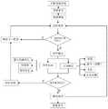
图3是道路中央应急联动驶入系统的流程图Figure 3 is a flow chart of the road central emergency linkage entry system
具体实施方式Detailed ways
下面详细描述本发明的实施例,所述实施例应参照附图理解。下面通过参考附图描述的实施例仅用于解释本发明具体的框架设计方法,而不理解为对本发明的限制。Embodiments of the present invention are described in detail below, which should be understood with reference to the accompanying drawings. The embodiments described below with reference to the accompanying drawings are only used to explain the specific frame design method of the present invention, and should not be construed as a limitation of the present invention.
本发明是基于发明人对以下事实的思考:按照我国《公路工程技术标准》所修建的高速公路能适应120km/h以上的运行速度。但实际上车辆的运行速度仅达到60~120km/h,不能满足日益增长的交通量需求,降低了高等级公路的服务水平,难以利用公路运输提供“门到门”服务。另外,驾驶员的出行质量和行车安全由生理状态和心理状态决定,而驾驶员的生心理状态受时间(如光照强度、温度)、空间(如道路线形、环境)等因素影响,难以确保稳定的驾驶状态,致使行车不安全、车速难以提高、出行效率低下。可见,如果能够提高公路上车辆的运行速度,减少车辆间的相互影响并避免驾驶人行为带来的行车不稳定性,就可以更有效地发挥公路“门到门”的优势,提高公路的服务水平。The present invention is based on the inventor's thinking on the fact that the expressway built in accordance with my country's "Technical Standards for Highway Engineering" can adapt to a running speed of more than 120km/h. However, in fact, the running speed of vehicles only reaches 60-120km/h, which cannot meet the increasing traffic demand, which reduces the service level of high-grade highways, and it is difficult to use road transportation to provide "door-to-door" services. In addition, the driving quality and driving safety of the driver are determined by the physiological state and psychological state, and the physiological and psychological state of the driver is affected by factors such as time (such as light intensity, temperature), space (such as road alignment, environment), etc., and it is difficult to ensure stability. The driving state is unsafe, the speed is difficult to increase, and the travel efficiency is low. It can be seen that if the running speed of the vehicles on the highway can be increased, the mutual influence between the vehicles can be reduced, and the driving instability caused by the driver's behavior can be avoided. Level.
与现有技术不同,本发明的思路是利用无人驾驶汽车来提供一种超高速私人陆地运输系统故障应急的框架设计方法,保障道路上其它正在高速行驶车辆的安全以及运输效率,实现私人陆地运输系统的高效性、安全性和可靠性。通过道路中央应急联动驶入系统,使无人驾驶车辆安全地运行于超高速公路,是一种根据车辆运行情况实时管控、实时决策的过程。该方法科学合理,从驾驶过程中剔除驾驶员差异的影响,降低事故率并具有一定的实用性。Different from the prior art, the idea of the present invention is to use an unmanned vehicle to provide a framework design method for emergency response to an ultra-high-speed private land transportation system, so as to ensure the safety and transportation efficiency of other high-speed vehicles on the road, and realize private land transportation. Efficiency, safety and reliability of transport systems. It is a process of real-time control and real-time decision-making according to the operation of the vehicle to make the unmanned vehicle run safely on the super-highway through the central emergency linkage system of the road. The method is scientific and reasonable, removes the influence of driver differences from the driving process, reduces the accident rate and has certain practicability.
一种超高速私人陆地运输系统车辆故障驶入方法,包括三个基本部分:分别为超高速公路、含主控系统的无人驾驶车辆、道路中央应急联动驶入系统。无人驾驶车辆在超高速公路上运行;道路中央应急联动驶入系统属于道路管理系统的子系统,其下又有三个子系统,分别故障车道车辆应急联动系统、救援车辆驶入联动系统及救援车辆驶出联动系统。含主控系统的无人驾驶车辆和道路中央应急联动驶入系统通过WIFI或者LTE网络相互连接,实现数据交换和控制管理。The invention discloses a method for vehicle failure driving into an ultra-high-speed private land transportation system, comprising three basic parts: a super-highway, an unmanned vehicle with a main control system, and a road central emergency linkage driving system. Unmanned vehicles run on super highways; the road central emergency linkage entry system is a subsystem of the road management system, and there are three subsystems under it, namely the emergency linkage system for vehicles in the fault lane, the linkage system for rescue vehicles entering and rescue vehicles Exit the linkage system. The unmanned vehicle with the main control system and the road central emergency linkage entry system are connected to each other through WIFI or LTE network to realize data exchange and control management.
具体步骤如下:Specific steps are as follows:
1.道路中央应急联动驶入系统包括数据处理系统和通信模块,道路中央应急联动驶入系统通过多个通信模块(通信模块1,2,...,n)接收车辆在超高速公路运行的数据信息,包括车道、道路桩号(范围)、运行速度、车距等实时信息,并将信息传递给对应的数据处理系统(数据处理系统1,2,...,n),通过数据处理系统对信息实时处理,转换成操作指令再反馈给通信模块,传递给含主控系统的无人驾驶车辆,实现故障车辆的发生以及故障的排除。1. The road central emergency linkage entry system includes a data processing system and a communication module. The road central emergency linkage entry system receives the information of vehicles running on the superhighway through multiple communication modules (communication modules 1, 2, ..., n). Data information, including real-time information such as lane, road station number (range), running speed, vehicle distance, etc., and transmit the information to the corresponding data processing system (data processing system 1, 2, ..., n), through data processing The system processes the information in real time, converts it into operation instructions, and then feeds it back to the communication module, and transmits it to the unmanned vehicle with the main control system, so as to realize the occurrence of faulty vehicles and the elimination of faults.
2.当无人驾驶车辆的主控系统发出请求时,道路管理系统将根据请求内容按照以下方案发出操作指令:2. When the main control system of the driverless vehicle sends a request, the road management system will issue an operation instruction according to the content of the request according to the following scheme:
(1)确认是否收到驶入请求或驶出请求。道路管理系统优先配合驶入、驶出系统的变道行为;某一行驶车辆发出变道信号时,系统将同时锁定本车道及目标车道的对应范围;当无人驾驶车辆的主控系统发出变道、超车或驶入、驶出请求时,道路管理系统通过当前时刻某车辆所处车道为i车道,桩号x,此后任意时刻锁定范围还包括车辆几何外形、安全富余及按运行速度所推算位置的值,从车头、车尾向外推算并加上安全距离,该安全距离由车辆之间的相对速度及车辆的机动性能进行推算;道路管理系统依据车辆的动力性能、当前位置、驾驶意图计算出未来一段时间内的位置及在任意时刻需要锁定的车道范围,车辆的主控系统通过控制车辆的行驶系统将车辆控制在锁定范围内;(1) Confirm whether an entry request or an exit request is received. The road management system preferentially cooperates with the lane-changing behavior of entering and exiting the system; when a driving vehicle sends a lane-changing signal, the system will lock the corresponding range of the current lane and the target lane at the same time; The road management system uses the lane of a vehicle at the current moment as lane i, station number x, and the locking range at any time thereafter also includes the geometry of the vehicle, the safety margin and the calculation based on the running speed. The value of the position is calculated from the front and rear of the vehicle and added to the safety distance. The safety distance is calculated from the relative speed between vehicles and the maneuverability of the vehicle; the road management system is based on the dynamic performance of the vehicle, current position, and driving intention. Calculate the position for a period of time in the future and the lane range that needs to be locked at any time, and the main control system of the vehicle controls the vehicle within the locked range by controlling the driving system of the vehicle;
进行空间锁定时,以Di表示车辆沿行进方向锁定距离,Dj表示侧向锁定距离;前后车辆存在速度差Δv时,车辆的前后锁定间距应相应变化。具体的锁定范围按照下述公式计算:When performing space locking, Di represents the locking distance of the vehicle along the traveling direction, and Dj represents the lateral locking distance; when there is a speed difference Δv between the front and rear vehicles, the front and rear locking distances of the vehicle should be changed accordingly. The specific locking range is calculated according to the following formula:
Di=0.5v+0.3ΔvDi =0.5v+0.3Δv
Dj=0.7+|0.1v|Dj =0.7+|0.1v|
Δv=v2-v1Δv=v2 -v1
其中,v2是后车的实时运行速度;v1是前车的实时运行速度。Δv为正时,为确保安全,车辆的前后锁定间距增大0.3Δv,反之减小。Among them, v2 is the real-time running speed of the following vehicle; v1 is the real-time running speed of the preceding vehicle. When Δv is positive, in order to ensure safety, the front and rear locking distance of the vehicle is increased by 0.3Δv, and vice versa.
进行时间锁定时,在锁定时长Tn内对车辆进行时空锁定,完成车辆请求后解除时空锁定,恢复正常运行。Tn包括等待时长Tw、插入时长Tm和时间差ΔT三部分,即:When time-locking is performed, the vehicle is time-space locked within the lock duration Tn, and the time-space lock is released after the vehicle request is completed, and normal operation is resumed. Tn includes three parts: waiting time Tw, insertion time Tm and time difference ΔT, namely:
Tn=Tw+Tm+ΔTTn =Tw +Tm +ΔT
等待时长Tw由车辆运行状况和数据交换周期决定。当下一周期目标车道可插入时,Tw=0;如下一周期目标车道不能插入,则执行等待指令,Tw=2t,t是等待周期数;插入时长Tm由车辆运行速度决定。时间差ΔT由前后车辆的运行速度和车间距决定。The waiting time Tw is determined by the vehicle operating conditions and the data exchange cycle. When the target lane can be inserted in the next cycle, Tw=0; if the target lane cannot be inserted in the next cycle, execute the waiting instruction, Tw=2t, t is the number of waiting cycles; the insertion duration Tm is determined by the vehicle running speed. The time difference ΔT is determined by the running speed of the front and rear vehicles and the distance between them.
(2)当车辆由外部道路驶入超高速公路时,先驶入匝道,从匝道入口到主线的行驶时间不少于系统数据交换周期,系统依据当前系统中运行车辆的实际状况计算主线车辆之间有无可用的间隙供车辆插入。具体方法为:先试图在下一个周期锁定车辆驶入所需要占用的空间位置,锁定成功则发出锁定指令和等待指令,如不成功,则发出指令让预期插入点之前的车辆加速,预期插入点之后的车辆减速,在运行车流中让出新加入车辆所需要的空间位置,使车辆驶入系统;如果上述方法均不能执行,那么新加入车辆在匝道上进入等待状态,等下一个信息交换周期再尝试进行插入位置占用锁定,直到完成驶入。(2) When the vehicle enters the super-highway from the external road, it enters the ramp first, and the travel time from the ramp entrance to the main line is not less than the system data exchange period. Whether there is an available gap for the vehicle to insert. The specific method is: first try to lock the space position that the vehicle needs to drive into in the next cycle. If the lock is successful, a lock command and a wait command will be issued. If it is unsuccessful, a command will be issued to accelerate the vehicle before the expected insertion point, and after the expected insertion point. If the above methods cannot be executed, the newly added vehicle will enter the waiting state on the ramp, and wait for the next information exchange cycle. Attempt a plug-in occupancy lock until the drive-in is complete.
(3)如果在主线上运行的车辆需要通过变道操作驶出本系统,在下一周期中目标车道上的临近的前方车辆尝试加速,后方车辆尝试减速,为需要变道驶出的车辆让出所需要的空间,以便于该车辆驶出系统。(3) If a vehicle running on the main line needs to exit the system through a lane change operation, in the next cycle, the adjacent vehicle in front on the target lane will try to accelerate, and the vehicle behind will try to decelerate to make way for the vehicle that needs to change lanes. The space required for the vehicle to exit the system.
(4)在主线上运行的车辆需要离开当前车道并进入临近车道时,先尝试在下一个周期内锁定当前车道及目标车道中的行驶位置,如果锁定成功,在进入目标车道后并经横向定位系统反馈数据确认后,在原车道中解除位置锁定;如果在临近的数据交换周期位置锁定不成功时,由在下一个锁定周期继续尝试变车道锁定。(4) When a vehicle running on the main line needs to leave the current lane and enter the adjacent lane, first try to lock the driving position in the current lane and the target lane in the next cycle. If the locking is successful, after entering the target lane, the lateral positioning system After the feedback data is confirmed, the position lock is released in the original lane; if the position lock is unsuccessful in the adjacent data exchange cycle, the attempt to change the lane is continued in the next lock cycle.
3.道路中央应急联动驶入系统属于道路管理系统的子系统,其下又有两个子系统,分别故障车道车辆应急联动系统、救援车辆驶入联动系统及救援车辆驶出联动系统,将道路上车道从右到左定义为1号车道、2号车道、3号车道等,定义故障车道为N号车道,并在道路设置时,将最左侧车道设置为应急车道(与当前高速最右侧车道为应急车道不同),定义为T号车道(T>N);3. The road central emergency linkage entry system belongs to the subsystem of the road management system, and there are two subsystems under it, namely the emergency linkage system for vehicles in the faulty lane, the linkage system for rescue vehicles entering and the linkage system for rescue vehicles exiting. The lanes are defined from right to left as lane 1, lane 2, lane 3, etc., and the fault lane is defined as lane N, and when the road is set, the leftmost lane is set as the emergency lane (the same as the rightmost lane of the current expressway). The lane is different from the emergency lane), which is defined as the T lane (T>N);
(1)故障车道车辆应急联动系统的操作逻辑如下:(1) The operation logic of the vehicle emergency linkage system in the faulty lane is as follows:
a.当检测到故障车辆发生故障时,故障车道车辆应急联动系统解除故障车辆后方车辆(定义这些车辆为F车辆,数量为X)的时空锁定,在故障车道车辆应急联动系统发出解除联动指令前,禁止车辆驶入故障车道,故障车辆之前的车辆保持时空锁定不变,其余车道仍然可以通过变道进入故障车辆前方车道,进入步骤b;a. When it is detected that the faulty vehicle is faulty, the vehicle emergency linkage system in the faulty lane releases the time-space lock of the vehicles behind the faulty vehicle (define these vehicles as F vehicles and the number is X). , the vehicle is prohibited from entering the faulty lane, the vehicle before the faulty vehicle remains locked in time and space, and the remaining lanes can still enter the lane in front of the faulty vehicle by changing lanes, and go to step b;
b.①若T=N+1,即故障车道与应急车道相邻,则所有F车辆变道进入T号车道,变道次序为距离故障车辆最近的F车辆先变道,其余车辆依次变道,变道完成后进入(2);b. ①If T=N+1, that is, the faulty lane is adjacent to the emergency lane, all F vehicles will change lanes and enter the T lane. The lane-changing sequence is that the F vehicle closest to the faulty vehicle changes lanes first, and the rest of the vehicles change lanes in turn. , enter (2) after the lane change is completed;
②若T>N+1,即故障车道与应急车道不相邻,由故障车道车辆应急联动系统计算所有F车辆变道进入N+1号车道的所需的时空位置,而后解除当前N+1号车道上这些时空位置上的X辆车的时空位置,定义其为G车辆;故障车道车辆应急联动系统计算所有G车辆变道进入N+2号车道的所需的时空位置,而后解除当前N+2号车道上这些时空位置上的X辆车的时空位置,定义其为H车辆,如此反复,直至解除T-1号车道X辆车的时空位置,定义为Z车辆,X辆Z车辆变道进入T号车道,变道次序为距离终点最近的Z车辆先变道,其余车辆依次变道,变道完成后,T-2号车道X辆解除时空锁定的车进入T-1号车道,变道次序为距离终点最近的车辆先变道,其余车辆依次变道,如此反复,直到N号车道X辆F车辆变道进入N+1号车道。当故障车道后方所有车辆有序插入相邻车道后保持稳定速度运行一个信息交换周期后,故障车道车辆应急联动系统发出解除联动指令,进入步骤(2)。②If T>N+1, that is, the faulty lane is not adjacent to the emergency lane, the vehicle emergency linkage system in the faulty lane calculates the required space-time positions for all F vehicles to change lanes into lane N+1, and then cancel the current N+1 The temporal and spatial positions of X vehicles at these temporal and spatial positions on lane No. 1 are defined as G vehicles; the vehicle emergency linkage system in the faulty lane calculates the required temporal and spatial positions of all G vehicles to change lanes into lane N+2, and then releases the current N The spatiotemporal position of the X vehicle at these spatiotemporal positions on the +2 lane is defined as the H vehicle, and so on, until the spatiotemporal position of the X vehicle in the T-1 lane is released, which is defined as the Z vehicle, and the X vehicle Z becomes the vehicle. The lane enters lane T, the lane change sequence is that the Z vehicle closest to the end changes lanes first, and the rest of the vehicles change lanes in turn. The lane-changing sequence is that the vehicle closest to the end changes lanes first, and the rest of the vehicles change lanes in turn, and so on, until the vehicle F in lane N changes lanes and enters lane N+1. When all the vehicles behind the faulty lane are inserted into the adjacent lanes in an orderly manner and keep a stable speed and run for an information exchange cycle, the emergency linkage system of the vehicles in the faulty lane sends out an unlinking command, and the process goes to step (2).
(2)救援车辆驶入联动系统的操作逻辑如下:(2) The operation logic of the rescue vehicle entering the linkage system is as follows:
救援车辆驶入故障车辆后方最近的一个匝道,当救援车辆由外部道路驶入专供无人驾驶车辆行驶的公路时,先驶入匝道,从匝道入口到主线的行驶时间不少于系统数据交换周期,救援车辆驶入联动系统依据当前系统中运行车辆的实际状况计算主线车辆之间有无可用的间隙供车辆插入。The rescue vehicle drives into the nearest ramp behind the faulty vehicle. When the rescue vehicle enters the road dedicated to unmanned vehicles from the external road, it will enter the ramp first, and the travel time from the ramp entrance to the main line is not less than the system data exchange. Period, the rescue vehicle enters the linkage system and calculates whether there is an available gap between the main line vehicles for the vehicle to insert according to the actual condition of the running vehicles in the current system.
具体方法为:先试图在下一个周期锁定车辆驶入所需要占用的空间位置,锁定成功则发出锁定指令和等待指令,如不成功,则发出指令让预期插入点之前的车辆加速,预期插入点之后的车辆减速,在运行车流中让出新加入车辆所需要的空间位置,使车辆驶入公路,当车辆进入故障车辆所处车道相邻车道时,救援车辆进入故障车道并慢慢减速靠近故障车辆并在故障车辆正后方停下将故障车辆拖入救援车辆上.当救援车辆发出救援成功指令后,救援车辆驶入联动系统发出解除联动指令。The specific method is: first try to lock the space position that the vehicle needs to drive into in the next cycle. If the lock is successful, a lock command and a wait command will be issued. If it is unsuccessful, a command will be issued to accelerate the vehicle before the expected insertion point, and after the expected insertion point. When the vehicle enters the lane adjacent to the faulty vehicle, the rescue vehicle enters the faulty lane and slowly decelerates to approach the faulty vehicle And stop right behind the faulty vehicle and drag the faulty vehicle into the rescue vehicle. When the rescue vehicle sends out a successful rescue command, the rescue vehicle drives into the linkage system to issue a disarming command.
Claims (1)
Translated fromChinese
Priority Applications (1)
| Application Number | Priority Date | Filing Date | Title |
|---|---|---|---|
| CN202111146714.XACN113706894B (en) | 2021-09-28 | 2021-09-28 | A method for vehicle failure entry of ultra-high-speed private land transportation system |
Applications Claiming Priority (1)
| Application Number | Priority Date | Filing Date | Title |
|---|---|---|---|
| CN202111146714.XACN113706894B (en) | 2021-09-28 | 2021-09-28 | A method for vehicle failure entry of ultra-high-speed private land transportation system |
Publications (2)
| Publication Number | Publication Date |
|---|---|
| CN113706894A CN113706894A (en) | 2021-11-26 |
| CN113706894Btrue CN113706894B (en) | 2022-08-12 |
Family
ID=78662246
Family Applications (1)
| Application Number | Title | Priority Date | Filing Date |
|---|---|---|---|
| CN202111146714.XAActiveCN113706894B (en) | 2021-09-28 | 2021-09-28 | A method for vehicle failure entry of ultra-high-speed private land transportation system |
Country Status (1)
| Country | Link |
|---|---|
| CN (1) | CN113706894B (en) |
Families Citing this family (1)
| Publication number | Priority date | Publication date | Assignee | Title |
|---|---|---|---|---|
| CN114202940B (en)* | 2021-12-31 | 2023-05-02 | 北京北大千方科技有限公司 | Traffic control system and method for emergency lane on expressway |
Citations (2)
| Publication number | Priority date | Publication date | Assignee | Title |
|---|---|---|---|---|
| WO2019025872A2 (en)* | 2018-11-26 | 2019-02-07 | Wasfi Alshdaifat | Autonomous city transportation means with artificial telepathy |
| CN111815989A (en)* | 2020-06-19 | 2020-10-23 | 勇鸿(重庆)信息科技有限公司 | C-V2X technology-based road accident rescue method and system |
- 2021
- 2021-09-28CNCN202111146714.XApatent/CN113706894B/enactiveActive
Patent Citations (2)
| Publication number | Priority date | Publication date | Assignee | Title |
|---|---|---|---|---|
| WO2019025872A2 (en)* | 2018-11-26 | 2019-02-07 | Wasfi Alshdaifat | Autonomous city transportation means with artificial telepathy |
| CN111815989A (en)* | 2020-06-19 | 2020-10-23 | 勇鸿(重庆)信息科技有限公司 | C-V2X technology-based road accident rescue method and system |
Non-Patent Citations (4)
| Title |
|---|
| 关于建立高速公路紧急救援系统的研究;蒲琪等;《上海铁道大学学报》;19991230(第12期);全文* |
| 车路协同技术在智慧高速建设中应用展望;刘志;《汽车工业研究》;20200305(第01期);全文* |
| 高速公路5G智能网联技术、方案和应用;吴冬升等;《电信科学》;20200420(第04期);全文* |
| 高速公路紧急救援路线选择路径模型;韩晓宇等;《长安大学学报(自然科学版)》;20130915(第05期);全文* |
Also Published As
| Publication number | Publication date |
|---|---|
| CN113706894A (en) | 2021-11-26 |
Similar Documents
| Publication | Publication Date | Title |
|---|---|---|
| CN113120038B (en) | Real-time compiling, decomposing and running organization method for fast and slow vehicles by adopting virtual marshalling technology | |
| CN106601002B (en) | Entrance ramp vehicle passing guiding system and method under Internet of vehicles environment | |
| US10896606B1 (en) | Emergency vehicle detection and right-of-way deference control in platooning | |
| CN107685749B (en) | A kind of train control system and method based on train-to-train communication | |
| CN110264698B (en) | Train running separation and recombination method | |
| CN113525461A (en) | A train operation control method for virtual formation | |
| CN106997690B (en) | A non-forced lane-changing control method for expressway vehicles in the Internet of Vehicles environment | |
| CN109035862A (en) | A kind of more vehicles collaboration lane-change control method based on truck traffic | |
| DE102020114366A1 (en) | SYSTEM AND METHOD OF CONTROLLING THE OPERATION OF AN AUTONOMOUS VEHICLE | |
| CN113511203B (en) | Vehicle formation following driving control method, system, equipment and storage medium | |
| WO2022127467A1 (en) | Method for controlling vehicles to drive as platoon, and related device | |
| Yu et al. | Fallback strategy for level 4+ automated driving system | |
| CN113706894B (en) | A method for vehicle failure entry of ultra-high-speed private land transportation system | |
| CN113734244B (en) | Control method of virtual continuous high-speed train under communication fault | |
| CN111762238B (en) | Train interval adjusting system and adjusting method thereof | |
| CN111325975B (en) | A centralized optimization and coordination method for intelligent networked vehicles in the entrance area | |
| CN114463974A (en) | Cooperative control system and method of mixed vehicle group under the condition of priority right of way | |
| CN116243603A (en) | Vehicle queue following control method and device for mixed traffic | |
| CN113870581B (en) | Control method for driving unmanned vehicle into road | |
| CN117141555A (en) | Method and device for controlling vehicle, computer equipment and storage medium | |
| CN113850707A (en) | Method for driving out vehicle fault of ultra-high-speed private land transportation system | |
| CN113781812B (en) | Control method for driverless vehicle to exit road | |
| CN113771879A (en) | A framework design method of road transportation system for unmanned vehicle driving | |
| CN115188178A (en) | Vehicle formation method, device, equipment and storage medium | |
| CN109559000A (en) | A vehicle platoon driving control method and management platform |
Legal Events
| Date | Code | Title | Description |
|---|---|---|---|
| PB01 | Publication | ||
| PB01 | Publication | ||
| SE01 | Entry into force of request for substantive examination | ||
| SE01 | Entry into force of request for substantive examination | ||
| GR01 | Patent grant | ||
| GR01 | Patent grant |