CN113697122B - A BIM-based unmanned aerial vehicle surveying and mapping device and surveying and mapping method - Google Patents
A BIM-based unmanned aerial vehicle surveying and mapping device and surveying and mapping methodDownload PDFInfo
- Publication number
- CN113697122B CN113697122BCN202111069261.5ACN202111069261ACN113697122BCN 113697122 BCN113697122 BCN 113697122BCN 202111069261 ACN202111069261 ACN 202111069261ACN 113697122 BCN113697122 BCN 113697122B
- Authority
- CN
- China
- Prior art keywords
- surveying
- mapping
- cylinder
- bim
- angle adjustment
- Prior art date
- Legal status (The legal status is an assumption and is not a legal conclusion. Google has not performed a legal analysis and makes no representation as to the accuracy of the status listed.)
- Expired - Fee Related
Links
Images


Classifications
- B—PERFORMING OPERATIONS; TRANSPORTING
- B64—AIRCRAFT; AVIATION; COSMONAUTICS
- B64D—EQUIPMENT FOR FITTING IN OR TO AIRCRAFT; FLIGHT SUITS; PARACHUTES; ARRANGEMENT OR MOUNTING OF POWER PLANTS OR PROPULSION TRANSMISSIONS IN AIRCRAFT
- B64D47/00—Equipment not otherwise provided for
- B64D47/08—Arrangements of cameras
- B—PERFORMING OPERATIONS; TRANSPORTING
- B64—AIRCRAFT; AVIATION; COSMONAUTICS
- B64D—EQUIPMENT FOR FITTING IN OR TO AIRCRAFT; FLIGHT SUITS; PARACHUTES; ARRANGEMENT OR MOUNTING OF POWER PLANTS OR PROPULSION TRANSMISSIONS IN AIRCRAFT
- B64D47/00—Equipment not otherwise provided for
- G—PHYSICS
- G01—MEASURING; TESTING
- G01C—MEASURING DISTANCES, LEVELS OR BEARINGS; SURVEYING; NAVIGATION; GYROSCOPIC INSTRUMENTS; PHOTOGRAMMETRY OR VIDEOGRAMMETRY
- G01C15/00—Surveying instruments or accessories not provided for in groups G01C1/00 - G01C13/00
- B—PERFORMING OPERATIONS; TRANSPORTING
- B64—AIRCRAFT; AVIATION; COSMONAUTICS
- B64U—UNMANNED AERIAL VEHICLES [UAV]; EQUIPMENT THEREFOR
- B64U2101/00—UAVs specially adapted for particular uses or applications
- B64U2101/30—UAVs specially adapted for particular uses or applications for imaging, photography or videography
Landscapes
- Engineering & Computer Science (AREA)
- Aviation & Aerospace Engineering (AREA)
- Physics & Mathematics (AREA)
- General Physics & Mathematics (AREA)
- Radar, Positioning & Navigation (AREA)
- Remote Sensing (AREA)
- Forklifts And Lifting Vehicles (AREA)
- Toys (AREA)
Abstract
Description
Translated fromChinese技术领域technical field
本发明属于测绘工程技术领域,特别是涉及一种基于BIM无人机测绘装置及测绘方法。The invention belongs to the technical field of surveying and mapping engineering, in particular to a BIM-based unmanned aerial vehicle surveying and mapping device and a surveying and mapping method.
背景技术Background technique
利用无人机作为机载激光雷达设备的载具,开展无人机低空激光雷达场区测绘工作,不仅能够有效提高测绘效率,而且获得的测绘成果信息化程度较高,能够同建筑信息模型(buildinginformationmodeling,BIM)技术相结合,BIM技术可以帮助实现建筑信息的集成,从建筑的设计、施工、运行直至建筑全寿命周期的终结,各种信息始终整合于一个三维模型信息数据库中,有效提高工作效率、节省资源、降低成本、以实现可持续发展。Using UAVs as the carrier of airborne lidar equipment to carry out UAV low-altitude lidar field surveying and mapping can not only effectively improve the efficiency of surveying and mapping, but also obtain a high degree of informatization of surveying and mapping results, which can be compared with building information models ( Building information modeling (BIM) technology, BIM technology can help realize the integration of building information, from the design, construction, operation of the building to the end of the building's life cycle, all kinds of information are always integrated in a 3D model information database, effectively improving the work Efficiency, saving resources, reducing costs to achieve sustainable development.
经检索,公告号CN112977859A,公告日期2021-06-18公开了一种基于BIM无人机测绘装置及测绘方法,包括机架,所述机架的一侧表面两端均固定连接有支腿,所述机架的一侧表面两端固定连接有固定块,所述固定块的一侧表面固定安装有第一电机,所述第一电机的一侧表面转动安装有螺纹杆,所述螺纹杆的一端转动连接有固定块的一侧表面,所述螺纹杆的表面通过螺纹孔螺纹连接有U型架,所述U型架的一端表面滑动连接于机架的一侧表面,所述U型架的另一侧表面固定安装有第二电机,所述第二电机的轴端转动安装有BIM测绘摄像机,所述BIM测绘摄像机的一端位于U型架的一侧表面,所述BIM测绘摄像机的另一端固定安装有镜头,这样能够大大提高使用的便利性和稳定性,保证测绘效率和精确度。After retrieval, the announcement number CN112977859A, announcement date 2021-06-18 discloses a surveying and mapping device and surveying method based on a BIM unmanned aerial vehicle, including a frame, and both ends of one side surface of the frame are fixedly connected with outriggers, A fixed block is fixedly connected to both ends of one side surface of the frame, a first motor is fixedly installed on one side surface of the fixed block, and a threaded rod is installed on one side surface of the first motor in rotation, and the threaded rod One end of one end is rotatably connected with one side surface of the fixed block, the surface of the threaded rod is threaded with a U-shaped frame through a threaded hole, one end surface of the U-shaped frame is slidably connected to one side surface of the frame, and the U-shaped A second motor is fixedly installed on the other side surface of the frame, and a BIM surveying and mapping camera is installed on the shaft end of the second motor. One end of the BIM surveying and mapping camera is located on one side of the U-shaped frame, and the BIM surveying and mapping camera The other end is fixed with a lens, which can greatly improve the convenience and stability of use, and ensure the efficiency and accuracy of surveying and mapping.
该专利存在以下不足之处:There are following deficiencies in this patent:
1.该测绘装置测绘方向单一,难以同时进行地貌的全面测量,且测量的精度也不够理想;1. The surveying and mapping device has a single surveying and mapping direction, and it is difficult to conduct a comprehensive survey of the landform at the same time, and the measurement accuracy is not ideal;
2.该测绘装置与无人机相固定,整体携带不便。2. The surveying and mapping device is fixed with the drone, so it is inconvenient to carry as a whole.
因此,现有的BIM测绘装置,无法满足实际使用中的需求,所以市面上迫切需要能改进的技术,以解决上述问题。Therefore, the existing BIM surveying and mapping devices cannot meet the needs in actual use, so there is an urgent need for improved technology in the market to solve the above problems.
发明内容Contents of the invention
本发明的目的在于提供一种基于BIM无人机测绘装置及测绘方法,通过设置多个筒体,使得该测绘装置能对不同方向的地形进行测绘,测绘的全面性更好,且机体、筒体和升降架之间可拼接,使得该测绘装置便于组装,解决了现有的测绘装置测绘方向单一,难以同时进行地貌的全面测量的问题。The purpose of the present invention is to provide a BIM-based unmanned aerial vehicle surveying and mapping device and surveying and mapping method. By setting multiple cylinders, the surveying and mapping device can survey and map terrain in different directions, and the comprehensiveness of surveying and mapping is better. The body and the lifting frame can be spliced, which makes the surveying and mapping device easy to assemble, and solves the problem that the existing surveying and mapping device has a single surveying and mapping direction, and it is difficult to perform comprehensive surveys of landforms at the same time.
为解决上述技术问题,本发明是通过以下技术方案实现的:In order to solve the problems of the technologies described above, the present invention is achieved through the following technical solutions:
本发明为一种基于BIM无人机测绘装置,包括机体、筒体和测绘机构,所述机体的底部从上到下依次设置有多个筒体,所述筒体内设置有测绘机构;The invention is a BIM-based unmanned aerial vehicle surveying and mapping device, including a body, a cylinder and a surveying and mapping mechanism. The bottom of the body is sequentially provided with a plurality of cylinders from top to bottom, and the cylinder is provided with a surveying and mapping mechanism;
所述筒体的顶面边缘处设置有多个沿圆周均匀分布的第一卡槽,所述筒体的底面边缘处设置有多个沿圆周均匀分布的第一卡块,所述第一卡块与第一卡槽相配合,且相邻筒体的第一卡块与第一卡槽通过两个对称分布的螺栓锁紧,所述筒体的侧面设置有供测绘机构穿过的通孔;The edge of the top surface of the cylinder is provided with a plurality of first clamping grooves uniformly distributed along the circumference, and the edge of the bottom surface of the cylinder is provided with a plurality of first clamping blocks uniformly distributed along the circumference. The block is matched with the first card slot, and the first block and the first card slot of the adjacent cylinder are locked by two symmetrically distributed bolts, and the side of the cylinder is provided with a through hole for the surveying and mapping mechanism to pass through ;
所述测绘机构包括伸缩机构、横向角度调节机构、竖向角度调节机构和测绘设备,所述伸缩机构固定在筒体的内部底面上,所述伸缩机构上设置有横向角度调节机构,所述横向角度调节机构上设置有竖向角度调节机构,所述竖向角度调节机构上安装有测绘设备。The surveying and mapping mechanism includes a telescopic mechanism, a lateral angle adjustment mechanism, a vertical angle adjustment mechanism and surveying and mapping equipment. A vertical angle adjustment mechanism is arranged on the angle adjustment mechanism, and surveying and mapping equipment is installed on the vertical angle adjustment mechanism.
进一步地,所述伸缩机构包括支撑板、第一电动推杆和第一导轨,所述支撑板滑动设置在第一导轨上,所述支撑板的端部通过第一连接块与第一电动推杆的活动端固定连接,所述第一电动推杆和第一导轨均固定在筒体内。Further, the telescopic mechanism includes a support plate, a first electric push rod and a first guide rail, the support plate is slidably arranged on the first guide rail, and the end of the support plate is connected to the first electric push rod through the first connecting block. The movable end of the rod is fixedly connected, and the first electric push rod and the first guide rail are both fixed in the barrel.
进一步地,所述横向角度调节机构包括第二电动推杆、第一齿条、第二导轨、第一齿轮和箱体,所述第二电动推杆的活动端通过第二连接块与第一齿条的端部固定连接,所述第一齿条滑动设置在第二导轨上,且所述第一齿条与第一齿轮相啮合,所述第一齿轮固定在箱体上,所述第二电动推杆和第二导轨均固定在支撑板的顶部。Further, the lateral angle adjustment mechanism includes a second electric push rod, a first rack, a second guide rail, a first gear and a box, and the movable end of the second electric push rod is connected to the first through the second connecting block. The end of the rack is fixedly connected, the first rack is slidably arranged on the second guide rail, and the first rack is engaged with the first gear, the first gear is fixed on the box, and the first Both the two electric push rods and the second guide rail are fixed on the top of the support plate.
进一步地,所述箱体的底面上设置有弧形滑轨,所述弧形滑轨与弧形滑槽滑动配合,所述弧形滑槽设置在支撑板的顶面上。Further, an arc-shaped slide rail is provided on the bottom surface of the box body, and the arc-shaped slide rail is slidingly matched with an arc-shaped slide groove, and the arc-shaped slide groove is arranged on the top surface of the support plate.
进一步地,所述竖向角度调节机构包括第三电动推杆、第二齿条、第二齿轮和转动架,所述第三电动推杆的活动端通过第三连接块与第二齿条的端部固定连接,所述第二齿条与第二齿轮相啮合,所述第二齿轮固定在转动架的一端,所述转动架通过销轴与箱体铰接,所述第三电动推杆固定在箱体内。Further, the vertical angle adjustment mechanism includes a third electric push rod, a second rack, a second gear and a turret, and the movable end of the third electric push rod passes through the connection between the third connecting block and the second rack. The ends are fixedly connected, the second rack is meshed with the second gear, the second gear is fixed on one end of the turret, the turret is hinged with the box through a pin shaft, and the third electric push rod is fixed inside the box.
进一步地,所述竖向角度调节机构还包括夹紧板和锁紧螺杆,所述转动架的另一端空腔内安装有测绘设备,所述测绘设备通过夹紧板夹紧,所述夹紧板通过锁紧螺杆锁紧。Further, the vertical angle adjustment mechanism also includes a clamping plate and a locking screw, surveying and mapping equipment is installed in the cavity at the other end of the turret, the surveying and mapping equipment is clamped by the clamping plate, and the clamping The plate is locked by locking screw.
进一步地,所述机体的底部固定有控制盒体,所述控制盒体的底面边缘处设置有多个沿圆周均匀分布的第二卡块,所述第二卡块与最上方筒体的第一卡槽相配合,且控制盒体与最上方筒体之间通过两个对称分布的螺栓锁紧。Further, a control box is fixed on the bottom of the body, and a plurality of second clamping blocks evenly distributed along the circumference are arranged at the edge of the bottom surface of the control box, and the second clamping blocks are connected with the first clamping block of the uppermost cylinder body. A card slot is matched, and the control box body and the uppermost cylinder body are locked by two symmetrically distributed bolts.
进一步地,还包括升降架,所述升降架包括底安装板和两个支撑脚,两个所述支撑脚对称设置在底安装板的两侧,所述底安装板的顶面边缘处设置有多个沿圆周均匀分布的第二卡槽,所述第二卡槽与最下方筒体的第一卡块相配合,且底安装板与最下方筒体之间通过两个对称分布的螺栓锁紧。Further, it also includes a lifting frame, the lifting frame includes a bottom mounting plate and two supporting feet, and the two supporting legs are symmetrically arranged on both sides of the bottom mounting plate, and the top surface edge of the bottom mounting plate is provided with A plurality of second card slots evenly distributed along the circumference, the second card slots are matched with the first block of the lowermost cylinder, and the bottom mounting plate and the lowermost cylinder are locked by two symmetrically distributed bolts tight.
进一步地,所述测绘设备设置为激光扫描仪、电磁波测距仪、数码相机或其他一些设备中的一种或几种,具体可基于现场实际状况及需要测绘的具体数据,加以选择。Further, the surveying and mapping equipment is set as one or more of laser scanners, electromagnetic wave rangefinders, digital cameras or other equipment, which can be selected based on actual site conditions and specific data required for surveying and mapping.
本发明亦提供一种基于BIM无人机测绘装置的测绘方法,包括以下步骤:The present invention also provides a surveying and mapping method based on a BIM unmanned aerial vehicle surveying and mapping device, comprising the following steps:
S1:测区勘察,并确定飞行航线;S1: survey area and determine the flight route;
S2:基于现场实际状况及需要测绘的具体数据,选择合适数量的筒体进行拼装,并确定各个筒体的方位,选择搭载合适的测绘设备,并将测绘设备固定安装好;S2: Based on the actual situation on site and the specific data required for surveying and mapping, select an appropriate number of cylinders for assembly, determine the orientation of each cylinder, select appropriate surveying and mapping equipment, and install the surveying and mapping equipment;
S3:将多个筒体与升降架、机体组装好;S3: Assemble multiple cylinders, lifting frames and bodies;
S4:启动机体,通过机体带动筒体上升,通过伸缩机构带动测绘设备伸出,通过测绘设备进行测绘,测绘过程中,通过横向角度调节机构调节测绘设备的水平方向角度,通过竖向角度调节机构调节测绘设备的竖直方向角度,全方位对该区域进行测绘,并将数据导入云端;S4: Start the body, drive the barrel up through the body, drive the surveying and mapping equipment to extend through the telescopic mechanism, and perform surveying and mapping through the surveying and mapping equipment. Adjust the vertical angle of the surveying and mapping equipment, survey and map the area in all directions, and import the data into the cloud;
S5:通过BIM软件进行分析,方便工程师快速开展场区规划设计。S5: Analysis through BIM software is convenient for engineers to quickly carry out site planning and design.
本发明具有以下有益效果:The present invention has the following beneficial effects:
1、本发明通过设置多个筒体,且筒体之间可通过第一卡槽、第一卡块、螺栓的配合相互拼接,使得该测绘装置能对不同方向的地形进行测绘,测绘的全面性更好,可基于现场实际状况及需要测绘的具体数据,自由选择合适数量的测绘机构,自由确定测绘机构的方位。1. The present invention arranges a plurality of cylinders, and the cylinders can be spliced with each other through the cooperation of the first clamping groove, the first clamping block and the bolt, so that the surveying and mapping device can survey and map terrain in different directions, and the surveying and mapping is comprehensive. Better performance, based on the actual situation of the site and the specific data required for surveying and mapping, the appropriate number of surveying and mapping institutions can be freely selected, and the orientation of the surveying and mapping institutions can be freely determined.
2、本发明通过设置第二卡块、第一卡槽、第一卡块和第二卡槽,使得机体、筒体和升降架之间可拼接,从而使得该测绘装置便于组装,故当不使用时,可将其拆解,从而便于携带。2. In the present invention, by setting the second clamping block, the first clamping slot, the first clamping block and the second clamping slot, the machine body, cylinder body and lifting frame can be spliced, so that the surveying and mapping device is easy to assemble, so when not When in use, it can be disassembled for easy portability.
3、本发明通过设置伸缩机构、横向角度调节机构和竖向角度调节机构,使得测绘设备在测绘时,可进行小范围的水平或竖直方向角度的调节,从而使得测绘更加方便,全面性更好,且在测绘设备不使用时,可通过伸缩机构将其缩回筒体内,避免损坏,在测绘设备使用时,可通过伸缩机构将其伸出筒体,方便测绘设备的测绘。3. The present invention provides a telescopic mechanism, a lateral angle adjustment mechanism, and a vertical angle adjustment mechanism, so that the surveying and mapping equipment can adjust a small range of horizontal or vertical angles during surveying and mapping, thereby making surveying and mapping more convenient and more comprehensive. Good, and when the surveying and mapping equipment is not in use, it can be retracted into the cylinder through the telescopic mechanism to avoid damage. When the surveying and mapping equipment is in use, it can be extended out of the cylinder through the telescopic mechanism to facilitate the surveying and mapping of the surveying and mapping equipment.
附图说明Description of drawings
为了更清楚地说明本发明实施例的技术方案,下面将对实施例描述所需要使用的附图作简单地介绍,显而易见地,下面描述中的附图仅仅是本发明的一些实施例,对于本领域普通技术人员来讲,在不付出创造性劳动的前提下,还可以根据这些附图获得其他的附图。In order to more clearly illustrate the technical solutions of the embodiments of the present invention, the following will briefly introduce the accompanying drawings that are required for the description of the embodiments. Obviously, the accompanying drawings in the following description are only some embodiments of the present invention. Those of ordinary skill in the art can also obtain other drawings based on these drawings without any creative effort.
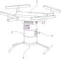
图1为本发明的整体结构外观示意图;Fig. 1 is the overall structural appearance schematic diagram of the present invention;
图2为本发明的筒体结构示意图;Fig. 2 is the schematic diagram of cylinder body structure of the present invention;
图3为本发明的测绘机构结构示意图;Fig. 3 is a structural schematic diagram of the surveying and mapping mechanism of the present invention;
图4为本发明的测绘机构爆炸示意图;Fig. 4 is the explosion schematic diagram of surveying and mapping mechanism of the present invention;
图5为本发明的伸缩机构结构示意图;Fig. 5 is a structural schematic diagram of the telescoping mechanism of the present invention;
图6为本发明的横向角度调节机构结构示意图;Fig. 6 is a structural schematic diagram of the lateral angle adjustment mechanism of the present invention;
图7为本发明的竖向角度调节机构结构示意图;Fig. 7 is a schematic structural diagram of the vertical angle adjustment mechanism of the present invention;
图8为本发明的机体结构示意图;Fig. 8 is a schematic diagram of the body structure of the present invention;
图9为本发明的升降架结构示意图。Fig. 9 is a structural schematic diagram of the lifting frame of the present invention.
附图中,各标号所代表的部件列表如下:In the accompanying drawings, the list of parts represented by each label is as follows:
1、机体;2、筒体;3、测绘机构;4、升降架;5、螺栓;11、控制盒体;12、第二卡块;21、第一卡槽;22、第一卡块;23、通孔;31、伸缩机构;32、横向角度调节机构;33、竖向角度调节机构;34、测绘设备;41、底安装板;42、支撑脚;43、第二卡槽;311、支撑板;312、第一电动推杆;313、第一连接块;314、第一导轨;315、弧形滑槽;321、第二电动推杆;322、第二连接块;323、第一齿条;324、第二导轨;325、第一齿轮;326、箱体;327、弧形滑轨;331、第三电动推杆;332、第三连接块;333、第二齿条;334、第二齿轮;335、转动架;336、销轴;337、夹紧板;338、锁紧螺杆。1. Body; 2. Cylinder; 3. Surveying and mapping mechanism; 4. Elevator; 5. Bolt; 11. Control box; 12. Second block; 21. First slot; 22. First block; 23. Through hole; 31. Telescopic mechanism; 32. Horizontal angle adjustment mechanism; 33. Vertical angle adjustment mechanism; 34. Surveying and mapping equipment; 41. Bottom mounting plate; 42. Supporting feet; 43. Second card slot; 311. Support plate; 312, the first electric push rod; 313, the first connecting block; 314, the first guide rail; 315, arc-shaped chute; 321, the second electric push rod; 322, the second connecting block; 323, the first Rack; 324, second guide rail; 325, first gear; 326, box body; 327, arc slide rail; 331, third electric push rod; 332, third connecting block; 333, second rack; 334 , the second gear; 335, the turret; 336, the bearing pin; 337, the clamping plate; 338, the locking screw.
具体实施方式Detailed ways
下面将结合本发明实施例中的附图,对本发明实施例中的技术方案进行清楚、完整地描述。The following will clearly and completely describe the technical solutions in the embodiments of the present invention with reference to the drawings in the embodiments of the present invention.
请参阅图1所示,本发明为一种基于BIM无人机测绘装置,包括机体1、筒体2和测绘机构3,机体1的底部从上到下依次设置有多个筒体2,筒体2内设置有测绘机构3。Please refer to Figure 1, the present invention is a BIM-based unmanned aerial vehicle surveying and mapping device, including a
其中如图2所示,筒体2的顶面边缘处设置有多个沿圆周均匀分布的第一卡槽21,筒体2的底面边缘处设置有多个沿圆周均匀分布的第一卡块22,第一卡块22与第一卡槽21相配合,且相邻筒体2的第一卡块22与第一卡槽21通过两个对称分布的螺栓5锁紧,筒体2的侧面设置有供测绘机构3穿过的通孔23。Wherein as shown in Figure 2, the top edge of the
其中如图3-4所示,测绘机构3包括伸缩机构31、横向角度调节机构32、竖向角度调节机构33和测绘设备34,伸缩机构31固定在筒体2的内部底面上,伸缩机构31上设置有横向角度调节机构32,横向角度调节机构32上设置有竖向角度调节机构33,竖向角度调节机构33上安装有测绘设备34,测绘设备34设置为激光扫描仪、电磁波测距仪、数码相机或其他一些设备中的一种或几种。Wherein as shown in Fig. 3-4, surveying and
其中如图5所示,伸缩机构31包括支撑板311、第一电动推杆312和第一导轨314,支撑板311滑动设置在第一导轨314上,支撑板311的端部通过第一连接块313与第一电动推杆312的活动端固定连接,第一电动推杆312和第一导轨314均固定在筒体2内。Wherein as shown in Figure 5,
伸缩机构31具体使用时,地面人员通过遥控设备启动第一电动推杆312,第一电动推杆312带动支撑板311沿着第一导轨314移动,支撑板311带动其上的横向角度调节机构32、竖向角度调节机构33、测绘设备34移动,从而将测绘设备34移出筒体2,方便测绘设备34的测绘。When the
其中如图6所示,横向角度调节机构32包括第二电动推杆321、第一齿条323、第二导轨324、第一齿轮325和箱体326,第二电动推杆321的活动端通过第二连接块322与第一齿条323的端部固定连接,第一齿条323滑动设置在第二导轨324上,且第一齿条323与第一齿轮325相啮合,第一齿轮325固定在箱体326上,第二电动推杆321和第二导轨324均固定在支撑板311的顶部,箱体326的底面上设置有弧形滑轨327,弧形滑轨327与弧形滑槽315滑动配合,弧形滑槽315设置在支撑板311的顶面上。Wherein as shown in Figure 6, the lateral
横向角度调节机构32具体使用时,地面人员通过遥控设备启动第二电动推杆321,第二电动推杆321带动第一齿条323沿着第二导轨324移动,第一齿条323带动第一齿轮325转动,第一齿轮325带动箱体326沿着弧形滑槽315转动,箱体326带动竖向角度调节机构33、测绘设备34转动,从而实现测绘设备34水平方向角度的调节。When the lateral
其中如图7所示,竖向角度调节机构33包括第三电动推杆331、第二齿条333、第二齿轮334和转动架335,第三电动推杆331的活动端通过第三连接块332与第二齿条333的端部固定连接,第二齿条333与第二齿轮334相啮合,第二齿轮334固定在转动架335的一端,转动架335通过销轴336与箱体326铰接,第三电动推杆331固定在箱体326内,竖向角度调节机构33还包括夹紧板337和锁紧螺杆338,转动架335的另一端空腔内安装有测绘设备34,测绘设备34通过夹紧板337夹紧,夹紧板337通过锁紧螺杆338锁紧。Wherein as shown in Figure 7, the vertical
竖向角度调节机构33具体使用时,将测绘设备34安装至转动架335的空腔中,并转动锁紧螺杆338,通过夹紧板337将测绘设备34锁紧,在无人机飞行过程中,地面人员通过遥控设备启动第三电动推杆331,第三电动推杆331带动第二齿条333移动,第二齿条333带动第二齿轮334转动,第二齿轮334带动转动架335转动,转动架335带动测绘设备34转动,从而实现测绘设备34竖直方向角度的调节。When the vertical
其中如图8所示,机体1的底部固定有控制盒体11,控制盒体11的底面边缘处设置有多个沿圆周均匀分布的第二卡块12,第二卡块12与最上方筒体2的第一卡槽21相配合,且控制盒体11与最上方筒体2之间通过两个对称分布的螺栓5锁紧。Wherein as shown in Figure 8, the bottom of the
其中如图9所示,还包括升降架4,升降架4包括底安装板41和两个支撑脚42,两个支撑脚42对称设置在底安装板41的两侧,底安装板41的顶面边缘处设置有多个沿圆周均匀分布的第二卡槽43,第二卡槽43与最下方筒体2的第一卡块22相配合,且底安装板41与最下方筒体2之间通过两个对称分布的螺栓5锁紧。Wherein as shown in Fig. 9, also comprise elevating
整个测绘装置组装时,首先将最下方筒体2的第一卡块22插入至升降架4的第二卡槽43内,并通过两个螺栓5锁紧,然后将上方筒体2的第一卡块22插入下方筒体2的第一卡槽21内,并通过两个螺栓5锁紧,将多个筒体2拼接在一起,最后将控制盒体11的第二卡块12插入最上方筒体2的第一卡槽21内,并通过两个螺栓5锁紧,即可完成整个组装过程。When the entire surveying and mapping device is assembled, first insert the
本发明亦提供一种基于BIM无人机测绘装置的测绘方法,包括以下步骤:The present invention also provides a surveying and mapping method based on a BIM unmanned aerial vehicle surveying and mapping device, comprising the following steps:
S1:测区勘察,并确定飞行航线;S1: survey area and determine the flight route;
S2:基于现场实际状况及需要测绘的具体数据,选择合适数量的筒体2进行拼装,并确定各个筒体2的方位,选择搭载合适的测绘设备34,并将测绘设备34固定安装好;S2: Based on the actual situation on the site and the specific data required for surveying and mapping, select an appropriate number of
S3:将多个筒体2与升降架4、机体1组装好;S3: Assemble a plurality of
S4:启动机体1,通过机体1带动筒体2上升,通过伸缩机构31带动测绘设备34伸出,通过测绘设备34进行测绘,测绘过程中,通过横向角度调节机构32调节测绘设备34的水平方向角度,通过竖向角度调节机构33调节测绘设备34的竖直方向角度,全方位对该区域进行测绘,并将数据导入云端;S4: Start the
S5:通过BIM软件进行分析,方便工程师快速开展场区规划设计。S5: Analysis through BIM software is convenient for engineers to quickly carry out site planning and design.
以上仅为本发明的优选实施例,并不限制本发明,任何对前述各实施例所记载的技术方案进行修改,对其中部分技术特征进行等同替换,所作的任何修改、等同替换、改进,均属于在本发明的保护范围。The above are only preferred embodiments of the present invention, and do not limit the present invention. Any modification to the technical solutions described in the foregoing embodiments, equivalent replacement of some of the technical features, any modification, equivalent replacement, and improvement are all Belong to the protection scope of the present invention.
Claims (8)
Translated fromChinesePriority Applications (1)
| Application Number | Priority Date | Filing Date | Title |
|---|---|---|---|
| CN202111069261.5ACN113697122B (en) | 2021-09-13 | 2021-09-13 | A BIM-based unmanned aerial vehicle surveying and mapping device and surveying and mapping method |
Applications Claiming Priority (1)
| Application Number | Priority Date | Filing Date | Title |
|---|---|---|---|
| CN202111069261.5ACN113697122B (en) | 2021-09-13 | 2021-09-13 | A BIM-based unmanned aerial vehicle surveying and mapping device and surveying and mapping method |
Publications (2)
| Publication Number | Publication Date |
|---|---|
| CN113697122A CN113697122A (en) | 2021-11-26 |
| CN113697122Btrue CN113697122B (en) | 2023-07-14 |
Family
ID=78660067
Family Applications (1)
| Application Number | Title | Priority Date | Filing Date |
|---|---|---|---|
| CN202111069261.5AExpired - Fee RelatedCN113697122B (en) | 2021-09-13 | 2021-09-13 | A BIM-based unmanned aerial vehicle surveying and mapping device and surveying and mapping method |
Country Status (1)
| Country | Link |
|---|---|
| CN (1) | CN113697122B (en) |
Families Citing this family (2)
| Publication number | Priority date | Publication date | Assignee | Title |
|---|---|---|---|---|
| CN112731442B (en)* | 2021-01-12 | 2023-10-27 | 桂林航天工业学院 | An adjustable surveying instrument for UAV surveying and mapping |
| CN116182813B (en)* | 2023-03-09 | 2024-02-06 | 菏泽市政工程设计研究院有限责任公司 | Building site survey and drawing device under special environment |
Family Cites Families (7)
| Publication number | Priority date | Publication date | Assignee | Title |
|---|---|---|---|---|
| CN206552283U (en)* | 2017-03-09 | 2017-10-13 | 西安为知电子科技有限公司 | A kind of equipment of taking photo by plane applied to unmanned plane |
| CN208530864U (en)* | 2018-05-22 | 2019-02-22 | 江苏爽飞信息科技有限公司 | Unmanned plane and its multi-angle oblique camera mounting bracket |
| CN209617527U (en)* | 2019-01-31 | 2019-11-12 | 深圳市世纪南方科技有限公司 | A kind of unmanned plane gas detection carry |
| CN213168584U (en)* | 2020-04-26 | 2021-05-11 | 焱行科技(上海)有限公司 | Unmanned aerial vehicle investigation recognition device |
| CN212195962U (en)* | 2020-05-29 | 2020-12-22 | 成都云瞰科技有限公司 | A camera suspension device for drone aerial photography |
| CN112977859B (en)* | 2021-04-08 | 2022-08-26 | 滨州职业学院 | Surveying and mapping device and method based on BIM unmanned aerial vehicle |
| CN113188019A (en)* | 2021-05-18 | 2021-07-30 | 河南慎远工程咨询有限公司 | Engineering mapping equipment appurtenance |
- 2021
- 2021-09-13CNCN202111069261.5Apatent/CN113697122B/ennot_activeExpired - Fee Related
Also Published As
| Publication number | Publication date |
|---|---|
| CN113697122A (en) | 2021-11-26 |
Similar Documents
| Publication | Publication Date | Title |
|---|---|---|
| CN113697122B (en) | A BIM-based unmanned aerial vehicle surveying and mapping device and surveying and mapping method | |
| CN103438864B (en) | Engineering slope real-time digital geological record system | |
| CN110319816A (en) | Geological record system based on photogrammetric technology and edit and record method | |
| CN103888738A (en) | Multisource multi-area-array GIS data acquisition platform for unmanned vehicle | |
| CN110009740A (en) | A fast 3D reconstruction method of geological outcrops based on motion recovery structure | |
| CN101701816B (en) | Method for collecting and processing geological exploration digital images in underground cave with large cross section | |
| CN103335606A (en) | Three dimensional laser scanning and surveying and mapping method | |
| CN1794786A (en) | Geologic digital image eliting and recording system and its use method | |
| CN112977859B (en) | Surveying and mapping device and method based on BIM unmanned aerial vehicle | |
| CN114283255B (en) | A panoramic image processing method for underground engineering inspection matching working condition time series | |
| Calantropio et al. | Use and evaluation of a short range small quadcopter and a portable imaging laser for built heritage 3D documentation | |
| CN109484630A (en) | A kind of multidirectional mapping erect bracket for complicated landform | |
| Zhang et al. | Research on Multi-Source Image Fusion Technology in the Digital Reconstruction of Classical Garden and Ancient Buildings | |
| CN218288131U (en) | Building mapping equipment based on unmanned aerial vehicle remote sensing | |
| CN217721284U (en) | All-in-one system for archaeological profile data collection | |
| CN214475708U (en) | Aerial photogrammetry simulation system | |
| CN202176334U (en) | Model test underground engineering tunneling drive device | |
| Wang | Application of Unmanned Aerial Vehicle Image Denoising Based on FPGA in Unmanned Aerial Vehicle Tilt Photography Assisted Intelligent Construction Site Management | |
| CN223308109U (en) | An automated collection device for core three-dimensional real scenes | |
| CN221569984U (en) | Image acquisition shooting device for ancient building digital display | |
| CN206627643U (en) | Building sunshine hour measuring system | |
| CN213657875U (en) | Survey and drawing auxiliary assembly for municipal works | |
| CN212691280U (en) | Photogrammetric device for ancient building stand column | |
| Cui et al. | The application of drone tilt photography in large scale topographic mapping | |
| CN220518593U (en) | Unmanned aerial vehicle survey and drawing's photographic arrangement |
Legal Events
| Date | Code | Title | Description |
|---|---|---|---|
| PB01 | Publication | ||
| PB01 | Publication | ||
| SE01 | Entry into force of request for substantive examination | ||
| SE01 | Entry into force of request for substantive examination | ||
| GR01 | Patent grant | ||
| GR01 | Patent grant | ||
| CF01 | Termination of patent right due to non-payment of annual fee | ||
| CF01 | Termination of patent right due to non-payment of annual fee | Granted publication date:20230714 |