Movatterモバイル変換


[0]ホーム

URL:


CN113631098B - Catheter for image diagnosis - Google Patents

Catheter for image diagnosis
Download PDF

Info

Publication number
CN113631098B
CN113631098BCN202080023578.2ACN202080023578ACN113631098BCN 113631098 BCN113631098 BCN 113631098BCN 202080023578 ACN202080023578 ACN 202080023578ACN 113631098 BCN113631098 BCN 113631098B
Authority
CN
China
Prior art keywords
ultrasonic
ultrasonic vibrator
catheter
sheath
image diagnosis
Prior art date
Legal status (The legal status is an assumption and is not a legal conclusion. Google has not performed a legal analysis and makes no representation as to the accuracy of the status listed.)
Active
Application number
CN202080023578.2A
Other languages
Chinese (zh)
Other versions
CN113631098A (en
Inventor
清水克彦
石原弘之
坂本泰一
桑野阳一郎
Current Assignee (The listed assignees may be inaccurate. Google has not performed a legal analysis and makes no representation or warranty as to the accuracy of the list.)
Terumo Corp
Original Assignee
Terumo Corp
Priority date (The priority date is an assumption and is not a legal conclusion. Google has not performed a legal analysis and makes no representation as to the accuracy of the date listed.)
Filing date
Publication date
Application filed by Terumo CorpfiledCriticalTerumo Corp
Priority to CN202310567296.4ApriorityCriticalpatent/CN116584971A/en
Publication of CN113631098ApublicationCriticalpatent/CN113631098A/en
Application grantedgrantedCritical
Publication of CN113631098BpublicationCriticalpatent/CN113631098B/en
Activelegal-statusCriticalCurrent
Anticipated expirationlegal-statusCritical

Links

Images

Classifications

Landscapes

Abstract

Translated fromChinese

本发明的图像诊断用导管具有:插入生物体内的护套;能够在所述护套内收发超声波的超声波振子;在所述护套内保持所述超声波振子的壳体;和安装于所述壳体的近位侧且能够在所述护套内旋转的驱动轴,所述超声波振子中的朝向所述护套的径向的超声波收发面以使远位端与近位端相比接近所述护套的内周面的方式相对于所述护套的延伸方向倾斜,所述壳体在所述超声波收发面的面内方向上没有遮挡所述超声波振子的远位侧。

Figure 202080023578

The catheter for image diagnosis of the present invention has: a sheath inserted into a living body; an ultrasonic vibrator capable of transmitting and receiving ultrasonic waves in the sheath; a housing holding the ultrasonic vibrator in the sheath; and a housing mounted on the housing. The proximal side of the body and the driving shaft that can rotate in the sheath, the ultrasonic transceiving surface facing the radial direction of the sheath in the ultrasonic vibrator makes the distal end closer to the said sheath than the proximal end. The shape of the inner peripheral surface of the sheath is inclined with respect to the extending direction of the sheath, and the housing does not block the distal side of the ultrasonic vibrator in the in-plane direction of the ultrasonic transmitting and receiving surface.

Figure 202080023578

Description

Translated fromChinese
图像诊断用导管Catheters for Image Diagnosis

技术领域technical field

本发明涉及图像诊断用导管。The present invention relates to a catheter for image diagnosis.

背景技术Background technique

作为获得血管等的断层图像的图像诊断用导管,从以往就知道通过血管内超声波诊断法(IVUS:Intra Vascular Ultra Sound)获得图像的图像诊断用导管。专利文献1中记载了这种图像诊断用导管。Catheters for image diagnosis that obtain images by intravascular ultrasound (IVUS: Intra Vascular Ultra Sound) are conventionally known as catheters for image diagnosis that obtain tomographic images of blood vessels and the like. Patent Document 1 describes such a catheter for image diagnosis.

现有技术文献prior art literature

专利文献patent documents

专利文献1:日本特开2017-56142号公报Patent Document 1: Japanese Patent Laid-Open No. 2017-56142

发明内容Contents of the invention

专利文献1所述的图像诊断用导管用于获得血管等细管的断层图像。专利文献1所述的图像诊断用导管考虑了例如在心腔内使用的情况。但是由于心脏的空间比血管大,所以为了获得清晰的断层图像,需要提高超声波的输出。本发明者经锐意探讨而发现因提高超声波的输出而出现了如下新问题:对象外的物体作为干扰容易反映于断层图像。The catheter for image diagnosis described in Patent Document 1 is used to obtain tomographic images of thin tubes such as blood vessels. The catheter for image diagnosis described in Patent Document 1 may be used, for example, in a cardiac cavity. However, since the space of the heart is larger than that of blood vessels, it is necessary to increase the output of ultrasonic waves in order to obtain clear tomographic images. The inventors of the present invention have found that the increase in the output of ultrasonic waves has resulted in a new problem that objects outside the target are easily reflected in the tomographic image as disturbances.

因此,本发明以提供一种图像诊断用导管为目的,该图像诊断用导管构成为,能够抑制对象外的物体作为干扰反映至断层图像。Therefore, an object of the present invention is to provide a catheter for image diagnosis configured to suppress reflection of an object outside the target as a disturbance on a tomographic image.

作为本发明的第1方式的图像诊断用导管具有:插入生物体内的护套;能够在所述护套内收发超声波的超声波振子;在所述护套内保持所述超声波振子的壳体;和安装于所述壳体的近位侧且能够在所述护套内旋转的驱动轴,所述超声波振子中的朝向所述护套的径向的超声波收发面以使远位端与近位端相比接近所述护套的内周面的方式相对于所述护套的延伸方向倾斜,所述壳体在所述超声波收发面的面内方向上没有遮挡所述超声波振子的远位侧。A catheter for image diagnosis according to a first aspect of the present invention includes: a sheath inserted into a living body; an ultrasonic vibrator capable of transmitting and receiving ultrasonic waves in the sheath; a case holding the ultrasonic vibrator in the sheath; and The driving shaft installed on the proximal side of the housing and capable of rotating in the sheath, the ultrasonic transceiving surface facing the radial direction of the sheath in the ultrasonic vibrator makes the distal end and the proximal end The case is inclined relative to the extending direction of the sheath so as to approach the inner peripheral surface of the sheath, and the housing does not shield the distal side of the ultrasonic vibrator in the in-plane direction of the ultrasonic transceiving surface.

作为本发明的一个实施方式,所述壳体的远位端与所述超声波振子的远位端相比没有位于远位侧,或者所述壳体在与所述超声波振子的远位端相比靠远位侧的位置,仅位于所述超声波振子的所述超声波收发面的背面侧。As an embodiment of the present invention, the distal end of the housing is not located on the distal side compared with the distal end of the ultrasonic vibrator, or the housing is located on the far side compared to the distal end of the ultrasonic vibrator. The position on the distal side is located only on the back side of the ultrasonic transmitting and receiving surface of the ultrasonic vibrator.

作为本发明的一个实施方式,所述超声波振子的远位端面包括弯曲面。As an embodiment of the present invention, the distal end surface of the ultrasonic vibrator includes a curved surface.

作为本发明的一个实施方式,所述壳体具有:相对于所述驱动轴以同轴状配置的近位筒部;和从所述近位筒部向远位侧突出并位于所述超声波振子的所述超声波收发面的背面侧的突出部。As an embodiment of the present invention, the housing has: a proximal cylindrical portion coaxially arranged with respect to the drive shaft; The protruding part on the back side of the ultrasonic transceiving surface.

作为本发明的一个实施方式,所述突出部的远位端与所述超声波振子的远位端相比没有位于远位侧,或者所述突出部在与所述超声波振子的远位端相比靠远位侧的位置,仅位于所述超声波振子的所述超声波收发面的背面侧。As an embodiment of the present invention, the distal end of the protruding portion is not located on the distal side compared with the distal end of the ultrasonic vibrator, or the protruding portion is located farther than the distal end of the ultrasonic vibrator. The position on the distal side is located only on the back side of the ultrasonic transmitting and receiving surface of the ultrasonic vibrator.

作为本发明的一个实施方式,在将所述超声波收发面所面对的一侧作为上侧,将其相反侧作为下侧的情况下,所述突出部与所述近位筒部的中心轴线相比位于下侧。As one embodiment of the present invention, when the side facing the ultrasonic transmitting and receiving surface is defined as the upper side and the opposite side is defined as the lower side, the central axis of the protruding portion and the proximal cylindrical portion compared to the lower side.

作为本发明的一个实施方式,所述图像诊断用导管具有位于所述突出部与所述超声波振子之间、并从所述超声波收发面的背面侧支承所述超声波振子的背面材料。As one embodiment of the present invention, the catheter for diagnostic imaging has a back material that is located between the protruding portion and the ultrasonic vibrator and supports the ultrasonic vibrator from the back side of the ultrasonic transceiving surface.

作为本发明的一个实施方式,所述突出部是与所述近位筒部的中心轴线方向正交的方向上的截面以圆弧状弯曲的凹状板部,所述背面材料的至少一部分位于所述凹状板部的凹部内。As an embodiment of the present invention, the protruding portion is a concave plate portion whose cross-section is curved in an arc shape in a direction perpendicular to the direction of the central axis of the proximal cylindrical portion, and at least a part of the backing material is located at the In the concave portion of the concave plate portion.

作为本发明的一个实施方式,所述背面材料具有将所述超声波振子的远位端面覆盖的远位覆盖部。As one embodiment of the present invention, the back material has a distal covering portion that covers the distal end surface of the ultrasonic vibrator.

作为本发明的一个实施方式,所述壳体没有覆盖所述超声波振子的侧端面,所述超声波振子的侧端面包含弯曲面。As an embodiment of the present invention, the housing does not cover the side end surface of the ultrasonic vibrator, and the side end surface of the ultrasonic vibrator includes a curved surface.

作为本发明的一个实施方式,所述背面材料包含使超声波散射的散射剂。As one embodiment of the present invention, the back surface material includes a scattering agent for scattering ultrasonic waves.

作为本发明的一个实施方式,所述超声波振子的位置与所述近位筒部的外周面相比处于径向的内侧。As one embodiment of the present invention, the position of the ultrasonic vibrator is radially inner than the outer peripheral surface of the proximal cylindrical portion.

发明效果Invention effect

根据本发明,能够提供一种图像诊断用导管,该图像诊断用导管构成为,能够抑制对象外的物体作为干扰反映至断层图像According to the present invention, it is possible to provide a catheter for image diagnosis that is configured to prevent objects outside the target from being reflected in a tomographic image as noise.

附图说明Description of drawings

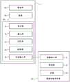
图1是表示作为本发明的一个实施方式的图像诊断用导管、和该图像诊断用导管所连接的图像处理装置的概略构成的框图。FIG. 1 is a block diagram showing a schematic configuration of a catheter for image diagnosis and an image processing device connected to the catheter for image diagnosis according to an embodiment of the present invention.

图2是表示图1所示的图像诊断用导管以及图像处理装置已连接的状态的概略图。FIG. 2 is a schematic diagram showing a state in which the catheter for image diagnosis and the image processing apparatus shown in FIG. 1 are connected.

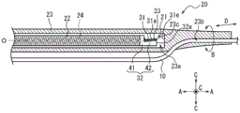
图3是表示图2所示的图像诊断用导管的远位侧的端部的剖视图。FIG. 3 is a cross-sectional view showing a distal-side end portion of the imaging diagnostic catheter shown in FIG. 2 .

图4是图3所示的成像核心部的侧视图。FIG. 4 is a side view of the imaging core shown in FIG. 3 .

图5是图3所示的成像核心部的俯视图。FIG. 5 is a top view of the imaging core shown in FIG. 3 .

图6是图5的I-I线处的剖视图。Fig. 6 is a sectional view taken along line I-I of Fig. 5 .

图7是表示图3所示的成像核心部的变形例的图,图7的(a)是成像核心部的侧视图,图7的(b)是成像核心部的俯视图。7 is a diagram showing a modified example of the imaging core shown in FIG. 3, FIG. 7(a) is a side view of the imaging core, and FIG. 7(b) is a plan view of the imaging core.

图8是表示图3所示的成像核心部的其他变形例的图。FIG. 8 is a diagram showing another modified example of the imaging core shown in FIG. 3 .

图9是表示图2所示的图像诊断用导管插穿至心脏的右心房内的状态的图。FIG. 9 is a diagram showing a state in which the catheter for image diagnosis shown in FIG. 2 is inserted into the right atrium of the heart.

具体实施方式Detailed ways

以下,参照附图来举例说明本发明的图像诊断用导管的实施方式。对于各图中共通的部件、部位标注相同的附图标记。另外,本说明书中,将本发明的图像诊断用导管的插入至脏器等的内部的一侧记载为“远位侧”或“顶端侧”,将进行操作的手边侧记载为“近位侧”或“基端侧”。而且,将本发明的图像诊断用导管的护套的延伸方向仅记载为“延伸方向A”,将本发明的图像诊断用导管的护套的周向仅记载为“周向B”,将本发明的图像诊断用导管的护套的径向仅记载为“径向C”。Hereinafter, embodiments of the catheter for image diagnosis of the present invention will be described with reference to the drawings. The same code|symbol is attached|subjected to the common member and part in each figure. In addition, in this specification, the side of the catheter for image diagnosis of the present invention inserted into an organ etc. is described as "distal side" or "tip side", and the side at hand where the operation is performed is described as "proximal side". ” or “basal side”. In addition, the extending direction of the sheath of the catheter for imaging diagnosis of the present invention is only described as "extending direction A", and the circumferential direction of the sheath of the catheter for imaging diagnosis of the present invention is only described as "circumferential direction B". The radial direction of the sheath of the catheter for imaging diagnosis of the invention is only described as "radial direction C".

图1是表示作为本发明的图像诊断用导管的一个实施方式的图像诊断用导管20、和该图像诊断用导管20所连接的图像处理装置1的概略构成的框图。图2是表示图像诊断用导管20以及图像处理装置1已连接的状态的概略图。图3表示图像诊断用导管20的远位侧的端部的剖视图。FIG. 1 is a block diagram showing a schematic configuration of an imagingdiagnostic catheter 20 as an embodiment of the imaging diagnostic catheter of the present invention and an image processing device 1 connected to the imagingdiagnostic catheter 20 . FIG. 2 is a schematic diagram showing a state in which thecatheter 20 for image diagnosis and the image processing device 1 are connected. FIG. 3 shows a cross-sectional view of the distal end of thediagnostic imaging catheter 20 .

如图1、图2所示,图像处理装置1具有驱动部50、基座59和图像处理部60。图像处理部60具有显示部51、输入部52、记忆部53、控制部54和信息输入部55。图像处理部60基于插入至生物体内的图像诊断用导管20的后述的成像核心部21所获得的脏器、血管或医疗器具的信息来生成断层图像。As shown in FIGS. 1 and 2 , the image processing device 1 has adrive unit 50 , abase 59 , and animage processing unit 60 . Theimage processing unit 60 has adisplay unit 51 , aninput unit 52 , amemory unit 53 , acontrol unit 54 , and aninformation input unit 55 . Theimage processing unit 60 generates a tomographic image based on information on organs, blood vessels, or medical instruments obtained by theimaging core unit 21 described later of thediagnostic image catheter 20 inserted into the living body.

如图1、图3所示,图像诊断用导管20具有成像核心部21、驱动轴22和护套23。图像处理装置1的信息输入部55与图像诊断用导管20的成像核心部21电连接。As shown in FIGS. 1 and 3 , thediagnostic imaging catheter 20 has animaging core 21 , adrive shaft 22 and asheath 23 . Theinformation input unit 55 of the image processing device 1 is electrically connected to theimaging core unit 21 of thecatheter 20 for image diagnosis.

成像核心部21获得心脏等脏器或血管(以下适当记载为“脏器等”。)、或者位于脏器等的内部的医疗器具的信息。具体地,成像核心部21具有超声波振子31。成像核心部21的超声波振子31向着脏器等或位于脏器等的内部的医疗器具发送超声波,并接收从该脏器等或该医疗器具反射的超声波。图像处理装置1经由信息输入部55,基于该成像核心部21的超声波振子31接收到的超声波信息来生成脏器等或医疗器具的断层图像。而且也可以为,图像处理装置1基于依次生成的多个断层图像,生成以及显示脏器等或医疗器具的三维图像。Theimaging core unit 21 obtains information on organs such as the heart, blood vessels (hereinafter referred to as "organs, etc." as appropriate), or medical instruments located inside the organs, etc. Specifically, theimaging core section 21 has anultrasonic vibrator 31 . Theultrasonic vibrator 31 of theimaging core 21 transmits ultrasonic waves toward an organ or the like or a medical instrument inside the organ or the like, and receives ultrasonic waves reflected from the organ or the like or the medical instrument. The image processing device 1 generates tomographic images of organs and the like or medical instruments based on ultrasonic information received by theultrasonic vibrator 31 of theimaging core unit 21 via theinformation input unit 55 . Furthermore, the image processing device 1 may generate and display a three-dimensional image of an organ or the like or a medical instrument based on a plurality of sequentially generated tomographic images.

驱动部50内置电机,与图像诊断用导管20的驱动轴22连结。如图3所示,成像核心部21安装在驱动轴22的远位侧。因为,驱动部50的旋转驱动力经由驱动轴22向成像核心部21传递。由此,成像核心部21在后述的护套23内能够沿周向B旋转。Thedrive unit 50 has a built-in motor, and is connected to thedrive shaft 22 of thediagnostic imaging catheter 20 . As shown in FIG. 3 , theimaging core 21 is installed on the distal side of thedrive shaft 22 . Because, the rotational driving force of thedriving unit 50 is transmitted to theimaging core unit 21 via thedriving shaft 22 . Thereby, theimaging core part 21 can rotate in the circumferential direction B in thesheath 23 mentioned later.

另外,如图2所示,驱动部50能够滑动移动地安装于基座59。图像诊断用导管20与安装在基座59上的驱动部50连接。驱动部50相对于基座59能够沿着延伸方向A移动。由此,与驱动部50连结的驱动轴22与驱动部50一同沿着延伸方向A移动。由此,关于安装在驱动轴22的远位侧的成像核心部21,也追随驱动轴22而在护套23内沿着延伸方向A移动。In addition, as shown in FIG. 2 , the drivingunit 50 is attached to the base 59 so as to be slidably movable. Thecatheter 20 for image diagnosis is connected to the drivingunit 50 attached to thebase 59 . Thedrive unit 50 is movable along the extending direction A relative to thebase 59 . Accordingly, thedrive shaft 22 connected to thedrive unit 50 moves along the extending direction A together with thedrive unit 50 . Accordingly, theimaging core 21 mounted on the distal side of thedrive shaft 22 also moves along the extending direction A within thesheath 23 following thedrive shaft 22 .

显示部51对由控制部54生成的显示信息进行显示输出。显示部51包括例如液晶显示器或有机EL显示器等的显示设备。Thedisplay unit 51 displays and outputs the display information generated by thecontrol unit 54 . Thedisplay unit 51 includes a display device such as a liquid crystal display or an organic EL display, for example.

输入部52受理基于操作者进行的信息或指示的输入,将受理的输入信息或输入指示向控制部54输出。输入部52例如包括键盘、鼠标或触摸面板等输入设备。在输入部52包含触摸面板的情况下,触摸面板也可以与显示部51一体设置。Theinput unit 52 accepts input of information or instructions from the operator, and outputs the accepted input information or input instructions to thecontrol unit 54 . Theinput unit 52 includes, for example, input devices such as a keyboard, a mouse, or a touch panel. When theinput unit 52 includes a touch panel, the touch panel may be provided integrally with thedisplay unit 51 .

记忆部53记忆用于在控制部54执行特定功能的各种信息以及程序。另外,记忆部53将由控制部54生成的被检查者的脏器等的断层图像记忆。记忆部53包含例如RAM或ROM等的记忆装置。Thestorage unit 53 stores various information and programs for executing specific functions in thecontrol unit 54 . In addition, thememory unit 53 stores tomographic images of the subject's organs and the like generated by thecontrol unit 54 . Thestorage unit 53 includes, for example, a storage device such as a RAM or a ROM.

控制部54控制构成图像处理装置1的各构成部的动作。控制部54通过读取特定程序来执行特定功能。控制部54包括例如处理器。Thecontrol unit 54 controls the operation of each constituent unit constituting the image processing device 1 . Thecontrol unit 54 executes a specific function by reading a specific program. Thecontrol unit 54 includes, for example, a processor.

信息输入部55受理成像核心部21所获得的脏器等、或位于脏器等的内部的医疗器具等的超声波信息的输入。具体地,信息输入部55经由延伸至驱动轴22内的信号线24与成像核心部21电连接,获得与成像核心部21所获得的超声波信息相关的信号,将该信号向控制部54发送。控制部54基于输入的信息来生成包括脏器等以及位于脏器等的内部的医疗器具在内的断层图像。Theinformation input unit 55 accepts input of ultrasound information on organs and the like obtained by theimaging core unit 21 , or on medical instruments and the like inside the organs and the like. Specifically, theinformation input unit 55 is electrically connected to theimaging core unit 21 via thesignal line 24 extending into thedrive shaft 22 , obtains a signal related to the ultrasonic information obtained by theimaging core unit 21 , and sends the signal to thecontrol unit 54 . Thecontrol unit 54 generates a tomographic image including organs and the like and medical instruments located inside the organs and the like based on the input information.

如图3所示,成像核心部21具有在护套23内能够收发超声波的超声波振子31、和在护套23内将超声波振子31保持的壳体32。As shown in FIG. 3 , theimaging core unit 21 has anultrasonic vibrator 31 capable of transmitting and receiving ultrasonic waves within thesheath 23 , and ahousing 32 that holds theultrasonic vibrator 31 within thesheath 23 .

如图3所示,超声波振子31具有能够收发超声波的超声波收发面31a。超声波收发面31a朝着径向C。也就是说,超声波振子31从超声波收发面31a主要地朝着径向C发送超声波。而且,超声波收发面31a以使远位端与近位端相比接近护套23的内周面的方式相对于延伸方向A倾斜。该详细内容后述。As shown in FIG. 3 , theultrasonic vibrator 31 has an ultrasonic transmitting and receivingsurface 31 a capable of transmitting and receiving ultrasonic waves. Theultrasonic transceiving surface 31a faces the radial direction C. That is, theultrasonic vibrator 31 mainly transmits ultrasonic waves in the radial direction C from the ultrasonic transmitting and receivingsurface 31 a. Furthermore, the ultrasonic transmitting and receivingsurface 31a is inclined with respect to the extending direction A so that the distal end is closer to the inner peripheral surface of thesheath 23 than the proximal end. The details will be described later.

超声波振子31朝着对象部位发送超声波,并接收从该对象部位反射的超声波。基于该超声波的从发送到接收的时间来获得离该对象部位的距离等的信息。Theultrasonic vibrator 31 transmits ultrasonic waves toward a target site, and receives ultrasonic waves reflected from the target site. Information such as the distance from the target site is obtained based on the time from transmission to reception of the ultrasonic waves.

如图3所示,壳体32保持超声波振子31。另外,壳体32在超声波收发面31a的面内方向D上没有遮挡超声波振子31的远位侧。“超声波收发面的面内方向”意味着与超声波收发面平行的任意方向。更具体地,本实施方式的壳体32的远位端32a与超声波振子31的远位端31e相比没有位于远位侧。该详细内容后述。As shown in FIG. 3 , thecase 32 holds theultrasonic vibrator 31 . In addition, thecasing 32 does not shield the distal side of theultrasonic vibrator 31 in the in-plane direction D of the ultrasonic transmitting and receivingsurface 31 a. "The in-plane direction of the ultrasonic transmission/reception surface" means any direction parallel to the ultrasonic transmission/reception surface. More specifically, in the present embodiment, thedistal end 32 a of thehousing 32 is not located on the distal side of thedistal end 31 e of theultrasonic vibrator 31 . The details will be described later.

驱动轴22安装在成像核心部21的壳体32的近位侧。另外,驱动轴22的近位侧的端部与上述的驱动部50连结。驱动轴22例如能够由绕着轴的卷绕方向不同的多层线圈构成。作为线圈的材料,例如能够举出不锈钢、Ni-Ti(镍-钛)合金等。Thedrive shaft 22 is installed on the proximal side of thehousing 32 of theimaging core 21 . In addition, the proximal end of thedrive shaft 22 is connected to thedrive unit 50 described above. Thedrive shaft 22 can be constituted by, for example, multilayer coils with different winding directions around the shaft. As a material of a coil, stainless steel, Ni-Ti (nickel-titanium) alloy etc. are mentioned, for example.

护套23是将成像核心部21以及驱动轴22的径向C外侧覆盖的具有挠性的管状部件。本实施方式中,护套23划分出供成像核心部21以及驱动轴22收容的第1腔室23a。另外,护套23在第1腔室23a之外还划分出能够供导丝10内插的第2腔室23b。在图3中表示成像核心部21以及驱动轴22收容于第1腔室23a且导丝10内插至第2腔室23b的状态。图像诊断用导管20沿着导丝10插入至脏器等。本实施方式的护套23虽然是仅在远位端部划分出第2腔室23b的快速更换类型(RX类型),但并不限于RX类型,例如也可以为整体更换类型(OTW类型)。Thesheath 23 is a flexible tubular member that covers theimaging core 21 and the outside of thedrive shaft 22 in the radial direction C. In this embodiment, thesheath 23 defines afirst chamber 23 a for housing theimaging core 21 and thedrive shaft 22 . In addition, thesheath 23 defines asecond chamber 23b into which theguide wire 10 can be inserted, in addition to thefirst chamber 23a. FIG. 3 shows a state in which theimaging core 21 and thedrive shaft 22 are housed in thefirst chamber 23 a and theguide wire 10 is inserted into thesecond chamber 23 b. Thecatheter 20 for image diagnosis is inserted into an organ or the like along theguide wire 10 . Although thesheath 23 of this embodiment is a quick exchange type (RX type) in which thesecond chamber 23b is defined only at the distal end, it is not limited to the RX type, and may be an integral exchange type (OTW type), for example.

护套23的第1腔室23a的远位端由壁部23c完全封闭。但护套23的第1腔室23a的远位端不限于被完全封闭的构成,也可以与外部连通,也可以设有如下壁部,该壁部形成有截面积比第1腔室23a小的贯穿孔。The distal end of thefirst chamber 23a of thesheath 23 is completely closed by thewall portion 23c. However, the distal end of thefirst chamber 23a of thesheath 23 is not limited to being completely closed, and may communicate with the outside, and may also be provided with a wall having a cross-sectional area smaller than that of thefirst chamber 23a. through holes.

护套23能够由具有挠性的材料形成。具体的护套23的材料没有特别限定,例如能够举出苯乙烯类、聚烯烃类、聚氨酯类、聚酯类、聚酰胺类、聚酰亚胺类、聚丁二烯类、反式聚异戊二烯类、氟橡胶类、氯化聚乙烯类等各种热塑性弹性体等、使其中的1种或2种以上组合而成的材料(混合物合金、聚合物共混物、层叠体等)。Thesheath 23 can be formed of a flexible material. The specific material of thesheath 23 is not particularly limited, and examples include styrene, polyolefin, polyurethane, polyester, polyamide, polyimide, polybutadiene, trans polyiso Various thermoplastic elastomers such as pentadiene, fluororubber, and chlorinated polyethylene, etc., materials that combine one or two or more of these (mixture alloys, polymer blends, laminates, etc.) .

接着更加详细说明图像诊断用导管20的成像核心部21。图4是成像核心部21的侧视图。图5是成像核心部21的俯视图。图6是图5的I-I线处的剖视图。在此,本实施方式的成像核心部21的侧视图意味着从超声波收发面31a看起来为线状的视角观察到的俯视图。另外,本实施方式的成像核心部21的俯视图意味着从超声波收发面31a侧观察成像核心部21的俯视图。Next, theimaging core 21 of thecatheter 20 for image diagnosis will be described in more detail. FIG. 4 is a side view of theimaging core section 21 . FIG. 5 is a plan view of theimaging core section 21 . Fig. 6 is a sectional view taken along line I-I of Fig. 5 . Here, the side view of theimaging core unit 21 in the present embodiment means a plan view viewed from a perspective in which the ultrasonic transmission/reception surface 31 a appears to be linear. In addition, the plan view of theimaging core part 21 in this embodiment means the plan view which looked at theimaging core part 21 from the side of the ultrasonic transmission/reception surface 31a.

上述那样地,成像核心部21具有超声波振子31以及壳体32。如图3、图4所示,超声波振子31的超声波收发面31a以使远位端与近位端相比接近护套23的内周面的方式相对于延伸方向A倾斜。As described above, theimaging core unit 21 has theultrasonic vibrator 31 and thehousing 32 . As shown in FIGS. 3 and 4 , the ultrasonic transmitting and receivingsurface 31 a of theultrasonic vibrator 31 is inclined with respect to the extending direction A such that the distal end is closer to the inner peripheral surface of thesheath 23 than the proximal end.

超声波振子31在例如提高超声波的输出等情况下,有时从超声波收发面31a以外的面发送超声波。在这样的情况下,从超声波振子31的远位端面31b发送的超声波有时被护套23的第1腔室23a的远位侧的壁部23c反射并由超声波收发面31a接收。由此,有可能发生对象外的物体、即护套23的壁部23c作为干扰反映至断层图像中的问题。Theultrasonic vibrator 31 may transmit ultrasonic waves from a surface other than the ultrasonic wave transmitting and receivingsurface 31 a when, for example, increasing the output of ultrasonic waves. In such a case, ultrasonic waves transmitted from thedistal end surface 31b of theultrasonic vibrator 31 may be reflected by thedistal wall portion 23c of thefirst chamber 23a of thesheath 23 and received by the ultrasonic transmitting and receivingsurface 31a. Accordingly, there is a possibility that an object outside the target, that is, thewall portion 23 c of thesheath 23 is reflected in the tomographic image as a disturbance.

但是,超声波振子31的超声波收发面31a以使远位端与近位端相比接近护套23的内周面的方向相对于延伸方向A倾斜。因此,即使从超声波振子31的远位端面31b发送了超声波,但与超声波收发面平行于护套的延伸方向A的构成相比较,超声波难以到达护套23的第1腔室23a的远位侧的壁部23c。另外,即使超声波到达了护套23的第1腔室23a的远位侧的壁部23c且被反射,但由于超声波收发面31a以趋向近位侧的方式倾斜,所以超声波收发面31a难以接收从护套23的第1腔室23a的远位侧的壁部23c反射的超声波。因此,能够抑制对象外的物体、即护套23的壁部23c作为干扰反映至断层图像内。However, the ultrasonic transmitting and receivingsurface 31 a of theultrasonic vibrator 31 is inclined with respect to the extending direction A in a direction in which the distal end is closer to the inner peripheral surface of thesheath 23 than the proximal end. Therefore, even if an ultrasonic wave is transmitted from thedistal end surface 31b of theultrasonic vibrator 31, it is difficult for the ultrasonic wave to reach the distal side of thefirst chamber 23a of thesheath 23 compared with the configuration in which the ultrasonic wave transmitting and receiving surface is parallel to the extending direction A of the sheath. Thewall portion 23c. In addition, even if the ultrasonic wave reaches and is reflected by thewall portion 23c on the distal side of thefirst chamber 23a of thesheath 23, the ultrasonic transmitting and receivingsurface 31a is inclined toward the proximal side, so the ultrasonic transmitting and receivingsurface 31a is difficult to receive the sound from the distal side. Ultrasonic waves reflected by thewall portion 23 c on the distal side of thefirst chamber 23 a of thesheath 23 . Therefore, it is possible to suppress the object outside the target, that is, thewall portion 23 c of thesheath 23 from being reflected in the tomographic image as a disturbance.

超声波收发面31a相对于延伸方向A的角度没有特别限定,例如优选为5°~15°,更优选为7°~12°。The angle of the ultrasonic wave transmitting and receivingsurface 31a with respect to the extending direction A is not particularly limited, and is, for example, preferably 5° to 15°, more preferably 7° to 12°.

而且,如图3、图4所示,壳体32在超声波收发面31a的面内方向D上没有遮蔽超声波振子31的远位侧。更具体地,本实施方式的壳体32的远位端32a与超声波振子31的远位端31e相比没有位于远位侧。在本实施方式中,壳体32的远位端32a的位置在延伸方向A上与超声波振子31的远位端31e的位置大致一致,但不限于该构成。壳体32的远位端32a也可以为,与超声波振子31的远位端31e相比位于近位侧。Furthermore, as shown in FIGS. 3 and 4 , thecasing 32 does not shield the distal side of theultrasonic vibrator 31 in the in-plane direction D of the ultrasonic transmitting and receivingsurface 31 a. More specifically, in the present embodiment, thedistal end 32 a of thehousing 32 is not located on the distal side of thedistal end 31 e of theultrasonic vibrator 31 . In the present embodiment, the position of thedistal end 32 a of thehousing 32 substantially coincides with the position of thedistal end 31 e of theultrasonic vibrator 31 in the extending direction A, but the configuration is not limited to this configuration. Thedistal end 32 a of thehousing 32 may be located on the proximal side of thedistal end 31 e of theultrasonic vibrator 31 .

通过将壳体32设为这样的构成,能够抑制从超声波振子31的超声波收发面31a以及远位端面31b发送的超声波被作为对象外物体的壳体32反射而作为超声波干扰由超声波收发面31a接收。也就是说,能够抑制作为对象外物体的壳体32作为干扰反映至断层图像。By setting thehousing 32 in such a configuration, it is possible to prevent the ultrasonic waves transmitted from the ultrasonic transmitting and receivingsurface 31 a and thedistal end surface 31 b of theultrasonic vibrator 31 from being reflected by thehousing 32 as an object outside the target and received by the ultrasonic transmitting and receivingsurface 31 a as ultrasonic interference. . That is, it is possible to suppress thecasing 32 which is an object outside the target from being reflected in the tomographic image as a disturbance.

然而也可以为,壳体在与超声波振子的远位端相比靠远位侧的位置,仅位于超声波振子的超声波收发面的背面侧(参照图7的(a)、图7的(b))。即使为这样的壳体,也能够获得上述同样的效果。However, it is also possible that the housing is positioned on the distal side compared to the distal end of the ultrasonic vibrator, and is located only on the back side of the ultrasonic transmitting and receiving surface of the ultrasonic vibrator (see FIG. ). Even with such a housing, the same effects as described above can be obtained.

以上那样地,根据图3、图4所示的成像核心部21,能够抑制超声波振子31从超声波收发面31a的面内方向D的远位侧接收成为干扰的超声波。也就是说,能够抑制对象外的物体作为干扰反映至断层图像。As described above, according to theimaging core unit 21 shown in FIGS. 3 and 4 , it is possible to prevent theultrasonic vibrator 31 from receiving disturbing ultrasonic waves from the distal side in the in-plane direction D of the ultrasonic transmitting and receivingsurface 31 a. In other words, it is possible to suppress objects outside the target from being reflected in the tomographic image as noise.

而且,如图5所示,本实施方式的超声波振子31的远位端面31b包含弯曲面。通过这样做,能够使从超声波振子31发送的超声波的行进方向分散。也就是说,从超声波振子31的远位端面31b发送的超声波难以到达护套23的壁部23c。由此,能够抑制作为对象外物体的护套23的壁部23c作为干扰反映至断层图像。Furthermore, as shown in FIG. 5 , thedistal end surface 31 b of theultrasonic vibrator 31 according to the present embodiment includes a curved surface. By doing so, it is possible to disperse the traveling directions of the ultrasonic waves transmitted from theultrasonic vibrator 31 . That is, ultrasonic waves transmitted from thedistal end surface 31 b of theultrasonic vibrator 31 are less likely to reach thewall portion 23 c of thesheath 23 . Accordingly, it is possible to suppress thewall portion 23 c of thesheath 23 , which is an object outside the target, from being reflected in the tomographic image as a disturbance.

本实施方式的远位端面31b是相对于超声波收发面31a大致正交的面。另外,本实施方式的远位端面31b当图5所示的俯视时是以圆弧状弯曲的凸面。但是远位端面31b的弯曲面的形状并不限于本实施方式的形状。远位端面31b可以例如在图4所示的侧视时是相对于超声波收发面31a倾斜的面,也可以在图4所示的侧视时是弯曲的面。另外,也可以在远位端面31b形成凹凸。然而优选为,远位端面31b如本实施方式那样地是相对于超声波收发面31a大致正交的面,在图5所示的俯视时是弯曲的凸状的弯曲面。通过这样做,容易将超声波收发面31a确保得宽阔,容易提高超声波输出。具有包含这种弯曲面的远位端面的超声波振子的俯视时的形状例如能够举出圆形状、椭圆形状、前方后圆鼓包形状等。Thedistal end surface 31b of the present embodiment is a surface substantially perpendicular to the ultrasonic transmission/reception surface 31a. In addition, thedistal end surface 31b of the present embodiment is a convex surface curved in an arc shape when viewed from above as shown in FIG. 5 . However, the shape of the curved surface of thedistal end surface 31b is not limited to the shape of this embodiment. Thedistal end surface 31b may be, for example, a surface inclined with respect to the ultrasonic transmitting and receivingsurface 31a in a side view shown in FIG. 4 , or may be a curved surface in a side view shown in FIG. 4 . In addition, unevenness may be formed on thedistal end surface 31b. However, it is preferable that thedistal end surface 31 b is a surface substantially perpendicular to the ultrasonic transmission/reception surface 31 a as in the present embodiment, and is a curved convex curved surface in plan view shown in FIG. 5 . By doing so, it is easy to ensure a wide ultrasonic transmission/reception surface 31a, and it is easy to increase the output of ultrasonic waves. Examples of the planar shape of an ultrasonic vibrator having a distal end surface including such a curved surface include a circular shape, an elliptical shape, and a front-rear swollen shape.

另外,超声波振子31中,不限于远位端面31b,有时从侧端面31c发送超声波。侧端面31c是与延伸方向A正交的方向上的端面。因此,本实施方式的超声波振子31的侧端面31c虽然由当图5所示的俯视时以直线状延伸的平面构成,但优选设为包含弯曲面的侧端面。通过这样做,与上述的远位端面31b同样地,难以使以从侧端面发送的超声波导致的超声波干扰反映至断层图像。图7是表示本实施方式的作为成像核心部21的变形例的成像核心部321的图。图7的(a)是成像核心部321的侧视图。图7的(b)是成像核心部321的俯视图。图7的(a)、图7的(b)所示的壳体32没有覆盖超声波振子331的侧端面331c。另外,超声波振子331的侧端面331c包含弯曲面。更具体地,图7的(a)、图7的(b)所示的超声波振子331中,远位端面331b以及侧端面331c当俯视时(参照图7的(b))构成了相连的连续圆弧形状。对于侧端面331c的形状也不限于图7所示的形状。但是,根据与上述的超声波振子31的远位端面31b(参照图5)同样的理由,优选为,如图7的(a)、图7的(b)所示的侧端面331c那样,是相对于超声波收发面331a大致正交的面,且是在俯视时弯曲的凸状的弯曲面。In addition, in theultrasonic vibrator 31 , not only thedistal end surface 31 b , ultrasonic waves may be transmitted from theside end surface 31 c. Theside end surface 31c is an end surface in a direction perpendicular to the extending direction A. As shown in FIG. Therefore, although theside end surface 31c of theultrasonic vibrator 31 of the present embodiment is constituted by a plane extending linearly in plan view as shown in FIG. 5 , it is preferably a side end surface including a curved surface. By doing so, similarly to the above-mentioneddistal end surface 31b, it becomes difficult to reflect the ultrasonic noise caused by the ultrasonic waves transmitted from the side end surface to the tomographic image. FIG. 7 is a diagram showing animaging core unit 321 as a modified example of theimaging core unit 21 according to the present embodiment. (a) of FIG. 7 is a side view of theimaging core part 321 . (b) of FIG. 7 is a plan view of theimaging core part 321 . Thecasing 32 shown in FIG. 7( a ) and FIG. 7( b ) does not cover theside end surface 331 c of theultrasonic vibrator 331 . In addition, theside end surface 331c of theultrasonic vibrator 331 includes a curved surface. More specifically, in theultrasonic vibrator 331 shown in Fig. 7(a) and Fig. 7(b), thedistal end surface 331b and theside end surface 331c form a connected continuous arc shape. The shape of theside end surface 331c is also not limited to the shape shown in FIG. 7 . However, for the same reason as the above-mentioneddistal end surface 31b (see FIG. 5 ) of theultrasonic vibrator 31, it is preferable that theside end surface 331c shown in FIG. 7(a) and FIG. The surface substantially perpendicular to the ultrasonic transmission/reception surface 331a is a convex curved surface that is curved in plan view.

然而,根据超声波振子的超声波的直线传播性的观点,优选设为由当俯视时以直线状延伸的平面构成的图5所示的侧端面31c。而且,根据超声波振子的超声波的直线传播性的观点,针对远位端面也优选由当俯视时以直线状延伸的平面构成。However, from the viewpoint of the rectilinear propagation of ultrasonic waves of the ultrasonic vibrator, it is preferable to use theside end surface 31 c shown in FIG. 5 constituted by a plane extending linearly in plan view. Furthermore, from the viewpoint of the rectilinear propagation of ultrasonic waves of the ultrasonic vibrator, it is also preferable that the distal end surface is constituted by a plane extending linearly in a planar view.

另外,图7的(a)、图7的(b)所示的成像核心部321的壳体32在与超声波振子331的远位端331e相比靠远位侧的位置,仅位于超声波振子331的超声波收发面331a的背面331d侧。因此,能够抑制壳体32作为干扰反映至断层图像。In addition, thecasing 32 of theimaging core part 321 shown in FIG. Theback surface 331d side of the ultrasonic wave transmitting and receivingsurface 331a. Therefore, it is possible to suppress thecase 32 from being reflected on the tomographic image as a disturbance.

再次返回本实施方式,参照图3~图6,进一步详细说明成像核心部21。Returning to this embodiment again, theimaging core unit 21 will be further described in detail with reference to FIGS. 3 to 6 .

本实施方式的成像核心部21在上述的超声波振子31以及壳体32的基础上,还具有背面材料33。Theimaging core unit 21 of the present embodiment further includes aback surface material 33 in addition to the above-describedultrasonic vibrator 31 andhousing 32 .

本实施方式的超声波振子31具有压电元件和音响匹配部件。压电元件由扁平状的压电体、层叠于该压电体的厚度方向的至少一侧的第1电极、和层叠于压电体的厚度方向的至少另一侧的第2电极构成。Theultrasonic vibrator 31 of this embodiment has a piezoelectric element and an acoustic matching member. The piezoelectric element is composed of a flat piezoelectric body, a first electrode stacked on at least one side of the piezoelectric body in the thickness direction, and a second electrode stacked on at least the other side of the piezoelectric body in the thickness direction.

压电元件的压电体例如由压电陶瓷片构成。作为压电陶瓷片的材料,例如能够举出锆钛酸铅(PZT)、铌酸锂等压电陶瓷材料。压电体也可以不是压电陶瓷材料,而由水晶形成。The piezoelectric body of the piezoelectric element is formed of, for example, a piezoelectric ceramic sheet. Examples of the piezoelectric ceramic sheet material include piezoelectric ceramic materials such as lead zirconate titanate (PZT) and lithium niobate. The piezoelectric body may be formed of crystal instead of piezoelectric ceramic material.

例如能够利用离子镀法、蒸镀法、溅镀法使掩模材料作为电极层分别层叠于压电体的厚度方向的两面,由此形成压电元件的第1电极以及第2电极。作为第1电极以及第2电极的材料,例如能够举出银、铬、铜、镍、金等金属和这些金属的层叠体等。For example, the first electrode and the second electrode of the piezoelectric element can be formed by laminating mask materials as electrode layers on both surfaces in the thickness direction of the piezoelectric body by ion plating, vapor deposition, or sputtering. Examples of materials for the first electrode and the second electrode include metals such as silver, chromium, copper, nickel, and gold, and laminates of these metals.

本实施方式的第1电极以及第2电极中的一个电极由折回电极构成。因此,如图5所示,信号线24仅在压电元件的厚度方向上的一侧分别与第1电极以及第2电极电连接。然而,第1电极以及第2电极也可以是分别仅位于压电元件的厚度方向的两侧的普通电极。One of the first electrode and the second electrode in this embodiment is constituted by a folded-back electrode. Therefore, as shown in FIG. 5 , thesignal line 24 is electrically connected to the first electrode and the second electrode only on one side in the thickness direction of the piezoelectric element. However, the first electrode and the second electrode may be ordinary electrodes located only on both sides in the thickness direction of the piezoelectric element.

音响匹配部件层叠于压电元件的厚度方向的一侧。通过设置音响匹配部件,能够提高超声波对被检查体的传播效率。也就是说,音响匹配部件构成了提高超声波的传播效率的音响匹配层。本实施方式的超声波收发面31a由该音响匹配部件构成。The acoustic matching component is laminated on one side in the thickness direction of the piezoelectric element. By providing the acoustic matching member, it is possible to improve the propagation efficiency of ultrasonic waves to the object to be inspected. That is, the acoustic matching member constitutes an acoustic matching layer that improves the propagation efficiency of ultrasonic waves. The ultrasonic transmission/reception surface 31a of this embodiment is comprised with this acoustic matching member.

作为音响匹配部件的音响匹配层,能够通过将形成音响匹配层的片材与压电元件贴合的方法、涂覆形成音响匹配层的液状音响匹配性材料并使其固化的方法等而形成。作为音响匹配部件的材料,例如能够举出环氧树脂等树脂材料。另外,音响匹配部件也可以通过由树脂材料构成的树脂层的层叠体构成。The acoustic matching layer of the acoustic matching member can be formed by a method of bonding a sheet forming the acoustic matching layer to a piezoelectric element, a method of coating and curing a liquid acoustic matching material forming the acoustic matching layer, or the like. As a material of an acoustic matching member, resin materials, such as epoxy resin, are mentioned, for example. In addition, the acoustic matching member may be constituted by a laminate of resin layers made of a resin material.

本实施方式的超声波振子31是通过对俯视时为1.5mm~2.5mm的矩形板状的远位侧的面施加凸状的弯曲面而形成。上述的图7所示的超声波振子331在俯视时具有1.5mm~2.5mm的外径。另外,从超声波振子31(参照图5等)以及331(参照图7)发送的超声波的输出频率为7MHz~20MHz。另外,从超声波振子31(参照图5等)以及331(参照图7)发送的超声波的发送电压例如为10Vp-p~100Vp-p。Theultrasonic vibrator 31 of the present embodiment is formed by adding a convex curved surface to the distal side surface of a rectangular plate-shaped surface of 1.5 mm to 2.5 mm in plan view. The above-mentionedultrasonic vibrator 331 shown in FIG. 7 has an outer diameter of 1.5 mm to 2.5 mm in plan view. In addition, the output frequency of the ultrasonic waves transmitted from the ultrasonic transducers 31 (see FIG. 5 etc.) and 331 (see FIG. 7 ) is 7 MHz to 20 MHz. In addition, the transmission voltage of the ultrasonic waves transmitted from the ultrasonic transducers 31 (see FIG. 5 etc.) and 331 (see FIG. 7 ) is, for example, 10 Vp-p to 100 Vp-p.

本实施方式的壳体32具有相对于驱动轴22以同轴状配置的近位筒部41、和从该近位筒部41向远位侧突出并位于超声波振子31的超声波收发面31a的背面31d侧的突出部42。通过设为这样的构成,能够由简单形状的壳体32来实现壳体32在超声波收发面31a的面内方向D上没有遮蔽超声波振子31的远位侧的构成。Thecase 32 of the present embodiment has a proximalcylindrical portion 41 arranged coaxially with thedrive shaft 22 , and a rear surface of the ultrasonic transmitting and receivingsurface 31 a protruding from the proximalcylindrical portion 41 to the distal side and positioned on theultrasonic vibrator 31 . Theprotrusion 42 on the 31d side. With such a configuration, it is possible to implement a configuration in which thehousing 32 does not shield the distal side of theultrasonic vibrator 31 in the in-plane direction D of the ultrasonic transmitting and receivingsurface 31 a by thehousing 32 having a simple shape.

更具体地,本实施方式的壳体32的远位端32a是突出部42的远位端。因此,如图3、图4所示,在本实施方式中,突出部42的远位端与超声波振子31的远位端31e相比没有位于远位侧。这样地,根据本实施方式的壳体32,能够由简单构成来实现在超声波收发面31a的面内方向D上没有遮蔽超声波振子31的远位侧的构成。尤其,突出部42优选为,在面内方向D上且在与延伸方向A正交的方向(以下记载为“宽度方向E”。)的整个区域内,与超声波振子31相比没有位于远位侧。也就是说,本实施方式的突出部42虽然在图5的俯视时在宽度方向E的两端部具有与超声波振子31相比位于远位侧的部分,但优选构成为,不具有这样的部分。根据这样做,能够更加抑制超声波振子31从远位侧接收成为干扰的超声波。而且,如图7的(b)所示,突出部42也可以为,在与超声波振子331的远位端331e相比靠远位侧的位置,仅位于超声波振子331的超声波收发面331a的背面侧。More specifically, thedistal end 32 a of thehousing 32 of the present embodiment is the distal end of the protrudingportion 42 . Therefore, as shown in FIGS. 3 and 4 , in the present embodiment, the distal end of the protrudingportion 42 is not located on the distal side of thedistal end 31 e of theultrasonic vibrator 31 . In this manner, according to thehousing 32 of the present embodiment, it is possible to implement a configuration in which the distal side of theultrasonic vibrator 31 is not shielded in the in-plane direction D of the ultrasonic transmitting and receivingsurface 31 a with a simple configuration. In particular, it is preferable that the protrudingportion 42 is not located farther than theultrasonic vibrator 31 in the entire area in the in-plane direction D and in a direction perpendicular to the extending direction A (hereinafter referred to as “width direction E”). side. That is, although the protrudingportion 42 of the present embodiment has portions on the distal side of theultrasonic vibrator 31 at both end portions in the width direction E in the plan view of FIG. 5 , it is preferable not to have such portions . By doing so, it is possible to further suppress theultrasonic vibrator 31 from receiving disturbing ultrasonic waves from the far side. Furthermore, as shown in (b) of FIG. 7 , the protrudingportion 42 may be located only on the back side of the ultrasonic transmitting and receivingsurface 331 a of theultrasonic vibrator 331 at a position on the distal side compared with thedistal end 331 e of theultrasonic vibrator 331 . side.

换言之,本实施方式的壳体32在侧视时(参照图4),具有直到远位端32a被切缺的切口部。并且超声波振子31配置于该切口部。In other words, thehousing 32 of the present embodiment has a notch cut away up to thedistal end 32 a in a side view (see FIG. 4 ). And theultrasonic vibrator 31 is arranged in this notch.

更具体地,突出部42是在与平行于近位筒部41的中心轴线的中心轴线方向(在护套23内与延伸方向A大致相等的方向)正交的方向上的截面(参照图6)处以圆弧状弯曲的凹状板部。换言之,本实施方式的突出部42由半筒状的弯曲板部构成。近位筒部41的中心轴线与驱动轴22的中心轴线一致,在护套23内与护套23的中心轴线大致一致。本实施方式中,将近位筒部41的中心轴线、驱动轴22的中心轴线以及护套23的中心轴线全都设为“中心轴线O”。图3中,为了便于说明,在护套23的内周面与壳体32的近位筒部41的外周面之间设有间隙,但实际上几乎不存在该间隙。也就是说,护套23的第1腔室23a的内径与近位筒部41的外径大致相等,近位筒部41的外周面在周向B上的多个部位或周向B整个区域内,与护套23的内周面抵接。More specifically, the protrudingportion 42 is a cross section in a direction perpendicular to the central axis direction parallel to the central axis of the proximal cylindrical portion 41 (a direction substantially equal to the extending direction A in the sheath 23) (see FIG. 6 ). ) is a concave plate portion bent in an arc shape. In other words, the protrudingportion 42 of the present embodiment is composed of a semi-cylindrical curved plate portion. The central axis of the proximalcylindrical portion 41 coincides with the central axis of thedrive shaft 22 , and substantially coincides with the central axis of thesheath 23 inside thesheath 23 . In this embodiment, the central axis of the proximalcylindrical portion 41 , the central axis of thedrive shaft 22 , and the central axis of thesheath 23 are all referred to as “central axis O”. In FIG. 3 , for convenience of description, a gap is provided between the inner peripheral surface of thesheath 23 and the outer peripheral surface of the proximalcylindrical portion 41 of thehousing 32 , but practically there is almost no such gap. That is to say, the inner diameter of thefirst chamber 23a of thesheath 23 is approximately equal to the outer diameter of the proximalcylindrical portion 41, and the outer peripheral surface of the proximalcylindrical portion 41 is located at multiple locations in the circumferential direction B or in the entire circumferential direction B. inside, abutting against the inner peripheral surface of thesheath 23 .

如图4所示,本实施方式的超声波振子31的位置与近位筒部41的外周面相比位于径向(护套23内与径向C大致相等的方向)的内侧。也就是说,本实施方式的超声波振子31与近位筒部41的外周面相比没有向径向外侧突出。通过这样做,即使近位筒部41的外周面与护套23的内周面滑动而旋转时,超声波振子31也难以与护套23的内周面抵接。也就是说,能够抑制超声波振子31因与护套23的内周面抵接而破损。As shown in FIG. 4 , theultrasonic vibrator 31 of the present embodiment is positioned on the inner side in the radial direction (a direction substantially equal to the radial direction C in the sheath 23 ) than the outer peripheral surface of the proximalcylindrical portion 41 . That is, theultrasonic vibrator 31 of the present embodiment does not protrude radially outward from the outer peripheral surface of the proximalcylindrical portion 41 . This makes it difficult for theultrasonic vibrator 31 to come into contact with the inner peripheral surface of thesheath 23 even when the outer peripheral surface of the proximalcylindrical portion 41 slides and rotates against the inner peripheral surface of thesheath 23 . That is, it is possible to suppress damage to theultrasonic vibrator 31 due to contact with the inner peripheral surface of thesheath 23 .

另外,如图4所示,本实施方式的作为突出部42的凹状板部的周向(护套23内与周向B大致相等的方向)的两侧的端面42a在侧视时相对于中心轴线方向倾斜地延伸。该详细内容后述。In addition, as shown in FIG. 4 , the end faces 42 a on both sides of the concave plate portion serving as the protrudingportion 42 in the circumferential direction (the direction substantially equal to the circumferential direction B in the sheath 23 ) of the present embodiment are opposite to the center in a side view. The axial direction extends obliquely. The details will be described later.

而且,如图5所示,超声波振子31的近位端面当俯视时配置在从近位筒部41向远位侧分离的位置。通过这样做,能够抑制从超声波振子31的超声波收发面31a发送的超声波被近位筒部41反射。该结果为,能够抑制超声波收发面31a接收被近位筒部41反射的成为干扰的超声波。而且也可以为,在没有延伸设置突出部42的周向区域内的近位筒部41的远位端,形成相对于延伸方向A倾斜的倾斜远位端部。该倾斜远位端部以越趋向远位侧而越接近突出部42的方式倾斜。根据这样做,从超声波振子31的超声波收发面31a发送的超声波难以到达近位筒部41。Furthermore, as shown in FIG. 5 , the proximal end surface of theultrasonic vibrator 31 is arranged at a position separated from theproximal tube portion 41 to the distal side in plan view. By doing so, it is possible to suppress reflection of the ultrasonic wave transmitted from the ultrasonic wave transmitting and receivingsurface 31 a of theultrasonic vibrator 31 by the proximalcylindrical portion 41 . As a result, it is possible to suppress reception of disturbing ultrasonic waves reflected by the proximalcylindrical portion 41 by the ultrasonic wave transmitting and receivingsurface 31 a. Furthermore, an inclined distal end portion inclined with respect to the extending direction A may be formed at the distal end of the proximalcylindrical portion 41 in the circumferential region where the protrudingportion 42 is not extended. The inclined distal end portion is inclined so as to approach the protrudingportion 42 as it goes to the distal side. This makes it difficult for the ultrasonic waves transmitted from the ultrasonic wave transmitting and receivingsurface 31 a of theultrasonic vibrator 31 to reach theproximal tube portion 41 .

作为壳体32的材料,例如能够举出不锈钢(SUS)、镍-钛合金(Ni-Ti)、钨等金属。Examples of the material of thehousing 32 include metals such as stainless steel (SUS), nickel-titanium alloy (Ni—Ti), and tungsten.

背面材料33位于突出部42与超声波振子31之间,从超声波收发面31a的背面31d侧支承超声波振子31。背面材料33是例如由橡胶和使钨粉末等金属粉末扩散的环氧树脂等构成的吸音体。通过设置该背面材料33,能够吸收从超声波振子31发送的成为干扰原因的一部分超声波。Theback surface material 33 is positioned between the protrudingportion 42 and theultrasonic vibrator 31 , and supports theultrasonic vibrator 31 from the back 31 d side of the ultrasonic transmitting and receivingsurface 31 a. Theback surface material 33 is, for example, a sound absorbing body made of rubber or epoxy resin in which metal powder such as tungsten powder is diffused. By providing theback surface material 33 , it is possible to absorb a part of ultrasonic waves transmitted from theultrasonic vibrator 31 that cause interference.

本实施方式的背面材料33覆盖超声波振子31的背面31d整个区域。由此,能够吸收从超声波振子31的背面31d发送的超声波。而且,本实施方式的背面材料33位于超声波振子31的近位侧,将超声波振子31的近位端面覆盖。也就是说,本实施方式的背面材料33不仅在超声波振子31的背面31d侧,也连续直到近位筒部41内,遍布近位筒部41内整个区域。由此,能够吸收从超声波振子31的近位端面发送的超声波。Theback surface material 33 of this embodiment covers the entire area of theback surface 31d of theultrasonic vibrator 31 . Thereby, the ultrasonic wave transmitted from theback surface 31d of theultrasonic vibrator 31 can be absorbed. Furthermore, theback surface material 33 of this embodiment is located on the proximal side of theultrasonic vibrator 31 and covers the proximal end surface of theultrasonic vibrator 31 . That is, theback surface material 33 of this embodiment is not only on theback surface 31 d side of theultrasonic vibrator 31 , but also continues into the proximalcylindrical portion 41 , covering the entire area in the proximalcylindrical portion 41 . Accordingly, ultrasonic waves transmitted from the proximal end surface of theultrasonic vibrator 31 can be absorbed.

背面材料33不限于超声波振子31的背面31d,也可以将超声波振子31的远位端面31b以及侧端面31c覆盖。通过这样做,能够由背面材料33吸收从超声波振子31的远位端面31b以及侧端面31c发送的超声波。因此,能够将从超声波振子31发送的成为干扰原因的一部分超声波进一步吸收。图8是表示作为成像核心部21的变形例的成像核心部421的图。图8所示的成像核心部421具有超声波振子31、壳体32和背面材料433。背面材料433不同于上述的背面材料33,具有将超声波振子31的远位端面31b覆盖的远位覆盖部433a。图8所示的背面材料433虽然具有将超声波振子31的远位端面31b覆盖的远位覆盖部433a,但并不限于该构成,可以作为在远位覆盖部433a的基础上或将其替代,而具有将超声波振子的侧端面覆盖的侧端覆盖部的背面材料。Theback surface material 33 is not limited to theback surface 31 d of theultrasonic vibrator 31 , and may cover thedistal end surface 31 b and theside end surface 31 c of theultrasonic vibrator 31 . By doing so, the ultrasonic waves transmitted from thedistal end surface 31 b and theside end surface 31 c of theultrasonic vibrator 31 can be absorbed by theback surface material 33 . Therefore, it is possible to further absorb part of the ultrasonic waves transmitted from theultrasonic vibrator 31 that cause interference. FIG. 8 is a diagram showing animaging core unit 421 as a modified example of theimaging core unit 21 . Theimaging core part 421 shown in FIG. 8 has theultrasonic vibrator 31 , thehousing 32 and theback material 433 . Theback surface material 433 is different from theback surface material 33 described above, and has adistal covering portion 433 a covering thedistal end surface 31 b of theultrasonic vibrator 31 . Although theback surface material 433 shown in FIG. 8 has adistal covering portion 433a covering thedistal end surface 31b of theultrasonic vibrator 31, it is not limited to this configuration, and may be based on or instead of thedistal covering portion 433a. On the other hand, the back material has a side end covering portion covering the side end surface of the ultrasonic vibrator.

另外,图8所示的背面材料433包括使超声波散射的散射剂。作为散射剂,例如能够举出玻璃粒、聚苯乙烯粒等。背面材料433的远位覆盖部433a包括这样的散射剂,由此能够在基于背面材料433实现的超声波的吸收效果的基础上,使从远位端面31b发送的超声波散射,从而能够进一步抑制超声波收发面31a接收成为干扰的超声波。In addition, theback surface material 433 shown in FIG. 8 includes a scattering agent for scattering ultrasonic waves. Examples of the scattering agent include glass particles, polystyrene particles, and the like. Thedistal covering portion 433a of theback material 433 includes such a scattering agent, so that the ultrasonic waves transmitted from thedistal end surface 31b can be scattered on the basis of the ultrasonic absorption effect realized by theback material 433, thereby further suppressing the transmission and reception of ultrasonic waves. Thesurface 31a receives ultrasonic waves that become disturbances.

另外,无论有无散射剂,背面材料433都优选为,与壳体32的近位筒部41的外周面相比没有向径向外侧伸出。通过这样做,能够抑制背面材料433与护套23(参照图3)的内周面抵接。In addition, regardless of the presence or absence of a scattering agent, it is preferable that theback surface material 433 does not protrude radially outward from the outer peripheral surface of the proximalcylindrical portion 41 of thehousing 32 . By doing so, it is possible to prevent theback surface material 433 from coming into contact with the inner peripheral surface of the sheath 23 (see FIG. 3 ).

再次参照图4、图6来说明本实施方式的成像核心部21。如上述那样,作为本实施方式的突出部42的凹状板部的周向两侧的端面42a在侧视时相对于中心轴线方向倾斜地延伸。另外,如图6所示,本实施方式的背面材料33具有:位于作为壳体32的突出部42的凹状板部的凹部42b内的主体部33c;和从该主体部33c突设并支承于凹状板部的周向的两侧的端面42a的凸缘部33d。因此,当向凹部42b内装填背面材料33的主体部33c时,使背面材料33的凸缘部33d支承于端面42a来定位。也就是说,通过利用端面42a,能够容易使背面材料33相对于作为突出部42的凹状板部进行定位。而且,如上述那样,端面42a当侧视时相对于中心轴线方向倾斜。因此,仅通过使背面材料33的凸缘部33d支承于端面42a来定位,就能够使支承超声波振子31的背面材料33的支承面33b相对于延伸方向A倾斜。因此,仅通过将与超声波收发面31a大致平行的背面31d载置于背面材料33的支承面33b,就能够容易实现使超声波收发面31a相对于延伸方向A以所希望的角度倾斜的状态。也就是说,能够容易实现以所希望的角度倾斜的超声波振子31的超声波收发面31a。Theimaging core unit 21 of this embodiment will be described with reference to FIGS. 4 and 6 again. As described above, the end surfaces 42a on both sides in the circumferential direction of the concave plate portion serving as the protrudingportion 42 of the present embodiment extend obliquely with respect to the central axis direction in a side view. In addition, as shown in FIG. 6, theback surface material 33 of this embodiment has: amain body part 33c located in the recessedpart 42b of the concave plate part which is the protrudingpart 42 of thehousing 32; Theflange part 33d of theend surface 42a of the both sides of the circumferential direction of a concave plate part. Therefore, when themain body part 33c of theback surface material 33 is loaded into the recessedpart 42b, theflange part 33d of theback surface material 33 is supported and positioned on theend surface 42a. That is, by using theend surface 42a, theback surface material 33 can be easily positioned with respect to the concave-shaped plate part which is theprotrusion part 42. As shown in FIG. Furthermore, as described above, theend surface 42a is inclined with respect to the central axis direction in a side view. Therefore, thesupport surface 33b of theback material 33 supporting theultrasonic vibrator 31 can be inclined with respect to the extending direction A simply by positioning theflange portion 33d of theback material 33 on theend surface 42a. Therefore, only by placing theback surface 31d substantially parallel to the ultrasonic transmitting and receivingsurface 31a on thesupport surface 33b of theback surface material 33, the state where the ultrasonic transmitting and receivingsurface 31a is inclined at a desired angle with respect to the extending direction A can be easily realized. That is, it is possible to easily realize the ultrasonic transmitting and receivingsurface 31 a of theultrasonic vibrator 31 inclined at a desired angle.

而且,将成像核心部21的超声波收发面31a所朝向的一侧设为上侧,将其相反侧设为下侧。在该情况下,在图4所示的侧视时,优选为,突出部42与近位筒部41的中心轴线O相比位于下侧。通过这样做,容易使超声波振子31的位置接近驱动轴22的中心轴线O的位置。通过使超声波振子31的位置接近驱动轴22的中心轴线O的位置,能够使超声波振子31的旋转稳定。另外,通过设为这样的构成,容易将信号线24向驱动轴22内引入。尤其,通过使超声波振子31的旋转的中心位置与驱动轴22的中心轴线O的位置一致,能够使超声波振子31的旋转更稳定。在本实施方式中,如图4所示,作为突出部42的凹状板部的周向两侧的端面42a的近位端在侧视时与近位筒部41的中心轴线O相比位于下侧。因此,如上述那样地,容易使超声波振子31的位置与驱动轴22的中心轴线O的位置对合。而且,通过使超声波振子31的位置接近驱动轴22的中心轴线O的位置,能够抑制伴随旋转的位置的变动,能够生成精度更高的生物体组织的断层图像。In addition, the side facing the ultrasonic transmission/reception surface 31 a of theimaging core unit 21 is defined as an upper side, and the opposite side is defined as a lower side. In this case, in a side view shown in FIG. 4 , it is preferable that the protrudingportion 42 is located below the central axis O of the proximalcylindrical portion 41 . By doing so, it is easy to bring the position of theultrasonic vibrator 31 closer to the position of the central axis O of thedrive shaft 22 . The rotation of theultrasonic vibrator 31 can be stabilized by making the position of theultrasonic vibrator 31 close to the position of the central axis O of thedrive shaft 22 . In addition, with such a configuration, it is easy to lead thesignal line 24 into thedrive shaft 22 . In particular, by making the center position of the rotation of theultrasonic vibrator 31 coincide with the position of the central axis O of thedrive shaft 22 , the rotation of theultrasonic vibrator 31 can be stabilized more. In the present embodiment, as shown in FIG. 4 , the proximal ends of the end surfaces 42 a on both sides of the concave plate portion as the protrudingportion 42 in the circumferential direction are located below the central axis O of the proximalcylindrical portion 41 in side view. side. Therefore, as described above, it is easy to align the position of theultrasonic vibrator 31 with the position of the central axis O of thedrive shaft 22 . Furthermore, by making the position of theultrasonic vibrator 31 close to the position of the central axis O of thedrive shaft 22 , it is possible to suppress positional fluctuations due to rotation, and to generate a more accurate tomographic image of living tissue.

主体部33c也可以不充满凹部42b内的全部空间。但若考虑超声波的吸收性能,则优选构成为,充满凹部42b内的全部空间。Themain body part 33c does not need to fill the entire space in the recessedpart 42b. However, in consideration of the absorption performance of ultrasonic waves, it is preferable that the entire space in theconcave portion 42b is filled.

另外,背面材料33具有上述的凸缘部33d,由此能够将壳体32的突出部42的端面42a由凸缘部33d覆盖。由此,能够抑制从超声波振子31发送的超声波被壳体32的突出部42的端面42a反射而作为超声波干扰被接收。Moreover, since theback surface material 33 has the above-mentionedflange part 33d, theend surface 42a of theprotrusion part 42 of thecase 32 can be covered with theflange part 33d. Accordingly, it is possible to prevent the ultrasonic waves transmitted from theultrasonic transducer 31 from being reflected by theend surface 42 a of the protrudingportion 42 of thecase 32 and received as ultrasonic noise.

最后,参照图9来说明使用本实施方式的图像诊断用导管20进行的手术的一例。图9中,表示插穿至心脏的右心房RA内的图像诊断用导管20。如图9所示,医疗从业者等操作者将图像诊断用导管20经由直径比被检查者的右心房RA小的作为第1血管的下大静脉IVC而插入至右心房RA内。此时,操作者将位于右心房RA内的作为医疗器具的穿刺针80经由下大静脉IVC,从引导导管84通过而插入至右心房RA内。穿刺针80用于贯穿将右心房RA和左心房LA隔离的卵圆窝H而从右心房RA将左心房LA开通。Finally, an example of surgery performed using thediagnostic image catheter 20 of this embodiment will be described with reference to FIG. 9 . FIG. 9 shows acatheter 20 for image diagnosis inserted into the right atrium RA of the heart. As shown in FIG. 9 , an operator such as a medical practitioner inserts thediagnostic image catheter 20 into the right atrium RA through the inferior venous vein IVC as a first blood vessel having a diameter smaller than that of the subject's right atrium RA. At this time, the operator inserts thepuncture needle 80 as a medical tool located in the right atrium RA into the right atrium RA through the inferior venous vein IVC, through theguide catheter 84 . Thepuncture needle 80 is used to penetrate the fossa ovalis H that separates the right atrium RA and the left atrium LA, and open the left atrium LA from the right atrium RA.

如图9所示,操作者将图像诊断用导管20的远位端部从右心房RA插入至直径比连通的右心房RA小的作为第2血管的上大静脉SVC。具体地,首先,将导丝10插入至上大静脉SVC,然后能够沿着导丝10将图像诊断用导管20的远位端部插入至上大静脉SVC。由此,抑制图像诊断用导管20的远位端部的振动。而且,图像诊断用导管20的近位侧进入至直径比右心房RA小的下大静脉IVC,由此图像诊断用导管20在直径比右心房RA小的上大静脉SVC和下大静脉IVC的范围内延伸,抑制图像诊断用导管20的位于右心房RA内的部分的振动以及移动。As shown in FIG. 9 , the operator inserts the distal end of the imagingdiagnostic catheter 20 from the right atrium RA into the superior venous vein SVC, which is a second blood vessel, which is smaller in diameter than the communicating right atrium RA. Specifically, first, theguide wire 10 is inserted into the superior venous vein SVC, and then the distal end portion of thediagnostic imaging catheter 20 can be inserted into the superior venous vein SVC along theguide wire 10 . Accordingly, the vibration of the distal end portion of thediagnostic imaging catheter 20 is suppressed. Furthermore, the proximal side of thecatheter 20 for image diagnosis enters the inferior venous vein IVC smaller in diameter than the right atrium RA, whereby thecatheter 20 for image diagnosis enters between the superior venous vein SVC and the inferior venous IVC smaller in diameter than the right atrium RA. The range is extended, and the vibration and movement of the portion of the imagingdiagnostic catheter 20 located in the right atrium RA are suppressed.

另外,通过使图像诊断用导管20的位于右心房RA内的部分弯曲,能够使收容有超声波振子31的护套23的第1腔室23a弯曲。这样地使第1腔室23a弯曲,能够使护套23的延伸方向A变化,使超声波振子31所移动的右心房RA内的位置变化。因此,能够接近例如脏器等的内壁面的特别想观察的部位(例如心脏的卵圆窝H)。In addition, by bending the portion of the catheter fordiagnostic imaging 20 located in the right atrium RA, thefirst chamber 23 a of thesheath 23 accommodating theultrasound vibrator 31 can be bent. By bending thefirst chamber 23a in this way, the extension direction A of thesheath 23 can be changed, and the position in the right atrium RA where theultrasonic vibrator 31 moves can be changed. Therefore, it is possible to approach a site particularly desired to be observed on the inner wall surface of an organ, for example (for example, the fossa ovale H of the heart).

超声波振子31在护套23的第1腔室23a内一边沿周向B旋转一边沿延伸方向A移动。在此期间,超声波振子31沿径向C发送超声波,并且接收被右心房RA的内壁面等反射的超声波。由此,超声波振子31作为周围信息而获得右心房RA的内壁面的位置信息。而且,超声波振子31作为周围信息而获得作为位于右心房RA内的医疗器具的穿刺针80的位置信息。并且,控制部54基于超声波振子31获得的周围信息来生成反映有右心房RA的内壁面的位置信、以及穿刺针80的位置信息的断层图像。Theultrasonic vibrator 31 moves in the extending direction A while rotating in the circumferential direction B in thefirst chamber 23 a of thesheath 23 . During this period, theultrasonic vibrator 31 transmits ultrasonic waves in the radial direction C, and receives ultrasonic waves reflected by the inner wall surface of the right atrium RA and the like. Thereby, theultrasonic transducer 31 obtains the position information of the inner wall surface of the right atrium RA as surrounding information. Furthermore, theultrasonic vibrator 31 acquires positional information of thepuncture needle 80 which is a medical instrument located in the right atrium RA as surrounding information. Then, thecontrol unit 54 generates a tomographic image reflecting the position information of the inner wall surface of the right atrium RA and the position information of thepuncture needle 80 based on the peripheral information obtained by theultrasonic transducer 31 .

上述那样地,在抑制了图像诊断用导管20的位于右心房RA内的部分的振动以及移动的状态下,使超声波振子31在护套23内移动,由此超声波振子31向周向B的旋转以及超声波振子31向延伸方向A的移动稳定。因此,能够稳定地获得右心房RA的内壁面的位置信息等周围信息。此时,记忆部53将超声波振子31沿延伸方向A移动时控制部54所生成的断层图像、与此时的超声波振子31的延伸方向A的位置建立关联地随时记忆。As described above, theultrasonic vibrator 31 is moved in thesheath 23 while the vibration and movement of the portion of the imagingdiagnostic catheter 20 located in the right atrium RA are suppressed, whereby theultrasonic vibrator 31 rotates in the circumferential direction B. And the movement of theultrasonic vibrator 31 in the extending direction A is stabilized. Therefore, peripheral information such as position information of the inner wall surface of the right atrium RA can be stably obtained. At this time, thememory unit 53 stores the tomographic image generated by thecontrol unit 54 when theultrasonic vibrator 31 moves in the extending direction A and the position in the extending direction A of theultrasonic vibrator 31 at that time and memorizes it at any time.

控制部54也可以使用记忆部53内所记忆的信息使断层图像层叠,由此生成右心房RA的三维图像。Thecontrol unit 54 may generate a three-dimensional image of the right atrium RA by stacking tomographic images using information stored in thestorage unit 53 .

图像诊断用导管20的超声波振子31如上述那样地以使超声波收发面31a(参照图4等)趋向近位侧的方式倾斜。因此,如图9所示,将超声波振子31与由穿刺针80穿刺的卵圆窝H相比更加配置在里侧,生成与超声波振子31的位置相比靠近位侧的断层图像,由此,容易获得穿刺针80顶端位置与穿刺针80的其他部分不重叠的断层图像。也就是说,通过构成为,超声波收发面31a(参照图4等)以朝向近位侧的方式倾斜,容易获得与图像诊断用导管20一同插入至生物体内来使用的医疗器具的顶端位置明确的断层图像。这并不限于图9所示的手术,只要是在如心房那样的生物体内的比较宽阔的空间内进行的手术,就能够同样地适用。Theultrasonic vibrator 31 of thecatheter 20 for image diagnosis is inclined such that the ultrasonic transmitting and receivingsurface 31 a (see FIG. 4 etc.) is directed toward the proximal side as described above. Therefore, as shown in FIG. 9 , theultrasonic vibrator 31 is arranged on the inner side of the fossa ovalis H punctured by thepuncture needle 80, and a tomographic image on the side of the position of theultrasonic vibrator 31 is generated. It is easy to obtain a tomographic image in which the position of the tip of thepuncture needle 80 does not overlap with other parts of thepuncture needle 80 . That is, by configuring the ultrasound transmitting and receivingsurface 31a (see FIG. 4 etc.) to be inclined toward the proximal side, it is easy to obtain a clear position of the distal end of the medical instrument used for insertion into the living body together with theimaging catheter 20 . Tomographic image. This is not limited to the operation shown in FIG. 9 , and it can be applied in the same way as long as it is performed in a relatively wide space in a living body such as the atrium.

另外,图9中作为脏器等的内腔的一例而表示了心脏的右心房RA,但本发明的图像诊断用导管20所插入的脏器等的内腔并没有特别限定,例如可以为心脏的左心房,也可以为心脏以外的脏器的内腔。In addition, in FIG. 9, the right atrium RA of the heart is shown as an example of the lumen of an organ or the like, but the lumen of an organ or the like into which thecatheter 20 for image diagnosis according to the present invention is inserted is not particularly limited, and may be, for example, the heart. The left atrium can also be the inner cavity of organs other than the heart.

本发明的图像诊断用导管不限于上述实施方式以及变形例所示的具体构造,只要不脱离技术方案的记载,就能够进行各种变形、变更。The catheter for image diagnosis of the present invention is not limited to the specific structures shown in the above-mentioned embodiments and modifications, and various modifications and changes are possible as long as they do not deviate from the description of the technical claims.

工业实用性Industrial Applicability

本发明涉及图像诊断用导管。The present invention relates to a catheter for image diagnosis.

附图标记说明Explanation of reference signs

1:图像处理装置1: Image processing device

10:导丝10: guide wire

20:图像诊断用导管20: Catheters for image diagnosis

21、321、421:成像核心部21, 321, 421: imaging core

22:驱动轴22: Drive shaft

23:护套23: sheath

23a:第1腔室23a: Chamber 1

23b:第2腔室23b:Chamber 2

23c:壁部23c: Wall

24:信号线24: signal line

31、331:超声波振子31, 331: Ultrasonic vibrator

31a、331a:超声波收发面31a, 331a: Ultrasonic transceiver surface

31b、331b:远位端面31b, 331b: distal end faces

31c、331c:侧端面31c, 331c: side end faces

31d、331d:背面31d, 331d: back

31e、331e:超声波振子的远位端31e, 331e: the distal end of the ultrasonic vibrator

32:壳体32: Shell

32a:壳体的远位端32a: Distal end of housing

33、433:背面材料33, 433: back material

33b:支承面33b: bearing surface

33c:主体部33c: Main body

33d:凸缘部33d: flange part

41:近位筒部41: proximal barrel

42:突出部42: protrusion

42a:端面42a: end face

42b:凹部42b: Recess

50:驱动部50: drive unit

51:显示部51: display unit

52:输入部52: input part

53:记忆部53: memory department

54:控制部54: Control Department

55:信息输入部55: Information input department

59:基座59: Base

60:图像处理部60: Image Processing Department

80:穿刺针80: puncture needle

84:引导导管84: Guide Catheter

433a:远位覆盖部433a: Distal covering

A:护套的延伸方向A: The extension direction of the sheath

B:护套的周向B: Circumferential direction of the sheath

C:护套的径向C: radial direction of sheath

D:超声波收发面的面内方向D: The in-plane direction of the ultrasonic transceiver surface

E:宽度方向E: Width direction

O:近位筒部、驱动轴以及护套的中心轴线O: Central axis of proximal barrel, drive shaft and sheath

LA:左心房LA: left atrium

RA:右心房RA: right atrium

IVC:下大静脉IVC: Inferior Great Vein

SVC:上大静脉。SVC: superior vein.

Claims (12)

CN202080023578.2A2019-03-272020-03-19Catheter for image diagnosisActiveCN113631098B (en)

Priority Applications (1)

Application NumberPriority DateFiling DateTitle
CN202310567296.4ACN116584971A (en)2019-03-272020-03-19Catheter for image diagnosis

Applications Claiming Priority (3)

Application NumberPriority DateFiling DateTitle
JP2019-0617692019-03-27
JP20190617692019-03-27
PCT/JP2020/012493WO2020196337A1 (en)2019-03-272020-03-19Image diagnosis catheter

Related Child Applications (1)

Application NumberTitlePriority DateFiling Date
CN202310567296.4ADivisionCN116584971A (en)2019-03-272020-03-19Catheter for image diagnosis

Publications (2)

Publication NumberPublication Date
CN113631098A CN113631098A (en)2021-11-09
CN113631098Btrue CN113631098B (en)2023-06-09

Family

ID=72609486

Family Applications (2)

Application NumberTitlePriority DateFiling Date
CN202310567296.4APendingCN116584971A (en)2019-03-272020-03-19Catheter for image diagnosis
CN202080023578.2AActiveCN113631098B (en)2019-03-272020-03-19Catheter for image diagnosis

Family Applications Before (1)

Application NumberTitlePriority DateFiling Date
CN202310567296.4APendingCN116584971A (en)2019-03-272020-03-19Catheter for image diagnosis

Country Status (5)

CountryLink
US (1)US20220008038A1 (en)
JP (2)JP7304409B2 (en)
CN (2)CN116584971A (en)
AU (2)AU2020248784B2 (en)
WO (1)WO2020196337A1 (en)

Families Citing this family (2)

* Cited by examiner, † Cited by third party
Publication numberPriority datePublication dateAssigneeTitle
WO2024176636A1 (en)*2023-02-212024-08-29テルモ株式会社Method for manufacturing catheter for diagnostic imaging, and catheter for diagnostic imaging
JP2024144888A (en)*2023-03-312024-10-15テルモ株式会社 Ultrasound Catheter

Citations (4)

* Cited by examiner, † Cited by third party
Publication numberPriority datePublication dateAssigneeTitle
US5655537A (en)*1994-11-301997-08-12Boston Scientific CorporationAcoustic imaging and doppler catheters and guidewires
CN102573654A (en)*2010-08-062012-07-11奥林巴斯医疗株式会社 Ultrasonic diagnostic device
JP2017093506A (en)*2015-11-182017-06-01テルモ株式会社Imaging diagnosis catheter
CN110809432A (en)*2017-06-292020-02-18泰尔茂株式会社 catheter for imaging diagnosis

Family Cites Families (7)

* Cited by examiner, † Cited by third party
Publication numberPriority datePublication dateAssigneeTitle
JPH0759776A (en)*1993-08-231995-03-07Aloka Co Ltd Ultrasonic probe for body cavity
US5842994A (en)*1997-07-021998-12-01Boston Scientific Technology, Inc.Multifunction intraluminal ultrasound catheter having a removable core with maximized transducer aperture
JP2005027957A (en)2003-07-092005-02-03Fujinon CorpUltrasonic oscillator and its mounting method
EP2358278B1 (en)*2008-12-082021-05-12Acist Medical Systems, Inc.System and catheter for image guidance and methods thereof
US9717475B2 (en)*2012-05-112017-08-01Volcano CorporationUltrasound catheter for imaging and blood flow measurement
WO2017027781A1 (en)*2015-08-122017-02-16Muffin IncorporatedDevice for three-dimensional, internal ultrasound with rotating transducer and rotating reflector
JP2017056142A (en)*2015-09-182017-03-23テルモ株式会社 Diagnostic imaging catheter

Patent Citations (4)

* Cited by examiner, † Cited by third party
Publication numberPriority datePublication dateAssigneeTitle
US5655537A (en)*1994-11-301997-08-12Boston Scientific CorporationAcoustic imaging and doppler catheters and guidewires
CN102573654A (en)*2010-08-062012-07-11奥林巴斯医疗株式会社 Ultrasonic diagnostic device
JP2017093506A (en)*2015-11-182017-06-01テルモ株式会社Imaging diagnosis catheter
CN110809432A (en)*2017-06-292020-02-18泰尔茂株式会社 catheter for imaging diagnosis

Also Published As

Publication numberPublication date
AU2023237114A1 (en)2023-10-19
AU2020248784B2 (en)2023-07-06
JP2023123681A (en)2023-09-05
JP7511059B2 (en)2024-07-04
JPWO2020196337A1 (en)2020-10-01
CN113631098A (en)2021-11-09
AU2020248784A1 (en)2021-11-11
WO2020196337A1 (en)2020-10-01
CN116584971A (en)2023-08-15
JP7304409B2 (en)2023-07-06
US20220008038A1 (en)2022-01-13

Similar Documents

PublicationPublication DateTitle
US11998389B2 (en)Focused rotational IVUS transducer using single crystal composite material
JP7511059B2 (en) Diagnostic Imaging Catheters
CA2799717C (en)Dual-mode piezocomposite ultrasonic transducer
WO2019031047A1 (en)Ultrasonic transducer, diagnostic ultrasonic probe, surgical instrument, sheet type ultrasonic probe, and electronic device
CN114145713A (en) A dual-frequency endoscopic catheter and imaging device
US20220015740A1 (en)Diagnostic imaging catheter
JP7403358B2 (en) ultrasonic probe
EP2783758A1 (en)Ultrasonic Probe and Manufacturing Method Thereof
US11406356B2 (en)Image diagnosis catheter
KR102607016B1 (en)Ultrasonic probe
CN113453627B (en)Ultrasonic vibrator
KR102757707B1 (en)Ultrasonic probe and ultrasonic imaging apparatus having the same
WuDesign, Fabrication and Characterization of Ultrasound Transducers and Arrays for Biomedical Imaging and Therapy
WO2021187251A1 (en)Ultrasonic probe
JP2023144742A (en)Catheter for diagnostic imaging
KR20140144411A (en)Ultrasound Probe and Manufacturing Method thereof

Legal Events

DateCodeTitleDescription
PB01Publication
PB01Publication
SE01Entry into force of request for substantive examination
GR01Patent grant
GR01Patent grant

[8]ページ先頭

©2009-2025 Movatter.jp