CN113618738A - Mechanical arm kinematic parameter calibration method and system - Google Patents
Mechanical arm kinematic parameter calibration method and systemDownload PDFInfo
- Publication number
- CN113618738A CN113618738ACN202110968698.6ACN202110968698ACN113618738ACN 113618738 ACN113618738 ACN 113618738ACN 202110968698 ACN202110968698 ACN 202110968698ACN 113618738 ACN113618738 ACN 113618738A
- Authority
- CN
- China
- Prior art keywords
- coordinate system
- measured
- pose
- calibration
- block
- Prior art date
- Legal status (The legal status is an assumption and is not a legal conclusion. Google has not performed a legal analysis and makes no representation as to the accuracy of the status listed.)
- Granted
Links
Images


Classifications
- B—PERFORMING OPERATIONS; TRANSPORTING
- B25—HAND TOOLS; PORTABLE POWER-DRIVEN TOOLS; MANIPULATORS
- B25J—MANIPULATORS; CHAMBERS PROVIDED WITH MANIPULATION DEVICES
- B25J9/00—Programme-controlled manipulators
- B25J9/16—Programme controls
- B25J9/1628—Programme controls characterised by the control loop
- B25J9/1653—Programme controls characterised by the control loop parameters identification, estimation, stiffness, accuracy, error analysis
- B—PERFORMING OPERATIONS; TRANSPORTING
- B25—HAND TOOLS; PORTABLE POWER-DRIVEN TOOLS; MANIPULATORS
- B25J—MANIPULATORS; CHAMBERS PROVIDED WITH MANIPULATION DEVICES
- B25J9/00—Programme-controlled manipulators
- B25J9/16—Programme controls
- B25J9/1656—Programme controls characterised by programming, planning systems for manipulators
- B25J9/1664—Programme controls characterised by programming, planning systems for manipulators characterised by motion, path, trajectory planning
Landscapes
- Engineering & Computer Science (AREA)
- Robotics (AREA)
- Mechanical Engineering (AREA)
- Length Measuring Devices With Unspecified Measuring Means (AREA)
- Manipulator (AREA)
Abstract
Translated fromChinese
Description
Translated fromChinese技术领域technical field
本发明涉及机械臂参数标定技术领域,特别是涉及一种机械臂运动学参数标定方法及系统。The invention relates to the technical field of mechanical arm parameter calibration, in particular to a mechanical arm kinematic parameter calibration method and system.
背景技术Background technique
机械臂是一种高度集成化的技术装备,它将机械、控制、电子与传感器等方向的技术有效的集合于一体,因此具有多方面的优点。其中,较为显著的特点在于它能协作工作人员做大量重复性工作,从而让工作人员避免了极端环境,进一步提高了工作效率。The robotic arm is a highly integrated technical equipment, which effectively integrates the technologies of mechanics, control, electronics and sensors, so it has many advantages. Among them, the more prominent feature is that it can collaborate with staff to do a lot of repetitive work, so that staff can avoid extreme environments and further improve work efficiency.
当前,机械臂实操的两种基本模式分别为:机械臂示教与离线编程。机械臂示教时间成本过高,需要专业人员进行手动逐点示教,导致自动化程度明显降低。为了提高自动化水平,通常选择离线编程的加工方式,但是由于加工、装配以及工作环境等因素,机械臂的实际结构参数与理论值存在一定偏差,使得机械臂的运动模型不准确,从而影响机械臂的绝对定位精度,这将对机械臂的广泛应用产生不利的影响,以至于无法按照理想的规划轨迹运动。At present, the two basic modes of manipulator operation are: manipulator teaching and offline programming. The teaching time cost of the robotic arm is too high, requiring professionals to teach point by point manually, resulting in a significant reduction in the degree of automation. In order to improve the level of automation, offline programming is usually selected. However, due to factors such as processing, assembly and working environment, there is a certain deviation between the actual structural parameters of the manipulator and the theoretical values, which makes the motion model of the manipulator inaccurate, thus affecting the manipulator. This will adversely affect the wide application of the robotic arm, so that it cannot move according to the ideal planned trajectory.
为了提高机械臂的自动化水平与定位精度,机械臂运动学参数标定成为当前攻破该难点的主流方向。在修正机械臂的运动学参数后,通过离线编程不仅实现了自动化操作,同时也提高机械臂的绝对定位精度。机械臂标定主要分为开环标定与闭环标定,开环标定主要是通过外部设备测量机械臂末端定位偏差,其中,测量设备通常有激光跟踪仪,三坐标测量仪、视觉跟踪系统等,虽然测量设备测量范围广,能实现自动化标定,但测量设备价格昂贵,增加了机械臂标定的成本;闭环标定通常需要设计对应的量块,基于空间中点、线、面等几何约束实现机械臂运动学参数的标定,该方法通常需要人工反复示教机械臂到达空间中特定的位置,其可操作较为繁琐,标定过程耗时较长,明显降低了标定效率,同时一些闭环标定方法具有较强的局限性,只能标定特定类型的机械臂。In order to improve the automation level and positioning accuracy of the manipulator, the kinematic parameter calibration of the manipulator has become the mainstream direction to overcome this difficulty. After correcting the kinematic parameters of the manipulator, offline programming not only realizes automatic operation, but also improves the absolute positioning accuracy of the manipulator. The robot arm calibration is mainly divided into open-loop calibration and closed-loop calibration. The open-loop calibration mainly measures the positioning deviation of the end of the robot arm through external equipment. Among them, the measurement equipment usually includes a laser tracker, a three-coordinate measuring instrument, a visual tracking system, etc. The equipment has a wide measurement range and can realize automatic calibration, but the measurement equipment is expensive, which increases the cost of the robot arm calibration; closed-loop calibration usually requires the design of corresponding gauge blocks, and realizes the kinematics of the robot arm based on geometric constraints such as points, lines, and surfaces in the space. For parameter calibration, this method usually requires manual repeated teaching of the manipulator to reach a specific position in the space. It is cumbersome to operate, and the calibration process takes a long time, which significantly reduces the calibration efficiency. At the same time, some closed-loop calibration methods have strong limitations. Only certain types of robotic arms can be calibrated.
针对上述方法所存在的问题,亟需建立一套通用性好、低成本、高效率、可操作强的机械臂运动学参数标定方法及系统。In view of the problems existing in the above methods, it is urgent to establish a method and system for calibrating the kinematic parameters of the manipulator with good versatility, low cost, high efficiency and strong operability.
发明内容SUMMARY OF THE INVENTION
本发明的目的是提供一种机械臂运动学参数标定方法及系统,以达到通用性好、低成本、高效率、可操作强的目的。The purpose of the present invention is to provide a method and system for calibrating kinematics parameters of a mechanical arm, so as to achieve the goals of good versatility, low cost, high efficiency and strong operability.
为实现上述目的,本发明提供了如下方案:For achieving the above object, the present invention provides the following scheme:
一种机械臂运动学参数标定方法,包括:A method for calibrating kinematic parameters of a robotic arm, comprising:
初始化标定装置,以确定位移传感器的零点位置,并根据所述零点位置,准确获得后续标定过程中位移传感器的安装位置与被测量块的被测平面的距离;所述标定装置是由六个位移传感器按照3-2-1六点定位方式组装的;所述被测量块为安装在待标定的机械臂末端上的量块;Initialize the calibration device to determine the zero position of the displacement sensor, and accurately obtain the distance between the installation position of the displacement sensor and the measured plane of the measured block in the subsequent calibration process according to the zero position; the calibration device is composed of six displacements. The sensor is assembled according to the 3-2-1 six-point positioning method; the measured block is a gauge block installed on the end of the robotic arm to be calibrated;
确定被测量块坐标系相对于所述标定装置坐标系的位姿;所述被测量块坐标系是在所述被测量块移至所述标定装置的测量范围后确定的;determining the pose of the coordinate system of the measured block relative to the coordinate system of the calibration device; the coordinate system of the measured block is determined after the measured block is moved to the measurement range of the calibration device;
基于所述被测量块坐标系相对于所述标定装置坐标系的位姿、第一定位偏差、第二定位偏差以及第三定位偏差,确定标定系统的运动学误差模型;所述标定系统为闭环系统;所述第一定位偏差为第一名义位姿与第一实际位姿之间的偏差;所述第一名义位姿为被测量块坐标系相对于机械臂末端坐标系的名义位姿,所述第一实际位姿为所述被测量块坐标系相对于机械臂末端坐标系的实际位姿;所述第二定位偏差为第二名义位姿与第二实际位姿之间的偏差,所述第二名义位姿为机械臂机座坐标系相对于标定装置坐标系的名义位姿,所述第二实际位姿为机械臂机座坐标系相对于标定装置坐标系的实际位姿;所述第三定位偏差为第三名义位姿与第三实际位姿之间的偏差;所述第三名义位姿为机械臂末端坐标系相对于机械臂机座坐标系的名义位姿;所述第三实际位姿为机械臂末端坐标系相对于机械臂机座坐标系的实际位姿;所述机械臂末端为待标定的机械臂末端,所述机械臂机座为待标定的机械臂机座;Based on the pose, the first positioning deviation, the second positioning deviation and the third positioning deviation of the coordinate system of the measured block relative to the coordinate system of the calibration device, a kinematic error model of the calibration system is determined; the calibration system is a closed loop system; the first positioning deviation is the deviation between the first nominal pose and the first actual pose; the first nominal pose is the nominal pose of the coordinate system of the measured block relative to the coordinate system of the end of the manipulator, The first actual pose is the actual pose of the coordinate system of the measured block relative to the coordinate system of the end of the manipulator; the second positioning deviation is the deviation between the second nominal pose and the second actual pose, The second nominal pose is the nominal pose of the manipulator base coordinate system relative to the calibration device coordinate system, and the second actual pose is the actual pose of the manipulator base coordinate system relative to the calibration device coordinate system; The third positioning deviation is the deviation between the third nominal pose and the third actual pose; the third nominal pose is the nominal pose of the coordinate system of the end of the manipulator relative to the coordinate system of the base of the manipulator; so The third actual pose is the actual pose of the coordinate system of the end of the manipulator relative to the coordinate system of the base of the manipulator; the end of the manipulator is the end of the manipulator to be calibrated, and the base of the manipulator is the manipulator to be calibrated Machine base;
获取测量数据;所述测量数据包括多组位移传感器采集的测量值以及每组所述测量值对应的待标定的机械臂的关节角度;acquiring measurement data; the measurement data includes measurement values collected by multiple groups of displacement sensors and joint angles of the robotic arm to be calibrated corresponding to each group of the measurement values;
基于所述标定系统的运动学误差模型和所述测量数据,对机械臂运动学参数进行标定。Based on the kinematic error model of the calibration system and the measurement data, the kinematic parameters of the robotic arm are calibrated.
可选的,所述初始化标定装置,以确定标定装置坐标系,具体包括:Optionally, the initialization of the calibration device to determine the coordinate system of the calibration device specifically includes:
将标定量块通过机械连接方式安装至所述标定装置上,并根据机械结构的几何尺寸,确定标定量块相对于标定装置的位姿关系,以及位移传感器安装位置到达被测平面的距离,并设置当前位移传感器的测量值为零,进而可以准确获得后续标定过程中位移传感器的安装位置与被测平面的距离;所述标定量块为与所述被测量块相同规格的量块。Install the calibration block on the calibration device through mechanical connection, and determine the pose relationship of the calibration block relative to the calibration device according to the geometric dimensions of the mechanical structure, and the distance from the installation position of the displacement sensor to the measured plane, and The measurement value of the current displacement sensor is set to zero, so that the distance between the installation position of the displacement sensor and the measured plane in the subsequent calibration process can be accurately obtained; the calibration block is a block of the same specification as the measured block.
可选的,所述确定被测量块坐标系相对于所述标定装置坐标系的位姿,具体包括:Optionally, the determining the pose of the coordinate system of the measured block relative to the coordinate system of the calibration device specifically includes:
构建被测量块坐标系;Construct the coordinate system of the measured block;
基于所述标定装置坐标系上的位移传感器的安装位置和测量方向,确定每个位移传感器基于所述标定装置坐标系下的空间直线方程;Based on the installation position and measurement direction of the displacement sensor on the calibration device coordinate system, determine the space straight line equation of each displacement sensor based on the calibration device coordinate system;
基于所述标定装置坐标系和所述被测量块坐标系,确定所述被测量块的被测平面方程;所述被测平面为所述被测量块所在平面;Determine the measured plane equation of the measured block based on the calibration device coordinate system and the measured block coordinate system; the measured plane is the plane where the measured block is located;
基于所述空间直线方程和所述位移传感器的测量值,确定每个所述位移传感器的安装位置与所述被测平面之间的测量距离;Determine the measurement distance between the installation position of each of the displacement sensors and the measured plane based on the space straight line equation and the measured value of the displacement sensor;
基于所述被测平面方程和所述测量距离,确定被测量块坐标系相对于所述标定装置坐标系的位姿。Based on the measured plane equation and the measured distance, the pose of the measured block coordinate system relative to the calibration device coordinate system is determined.
可选的,所述基于所述标定装置坐标系和所述被测量块坐标系,确定所述被测量块的被测平面方程,具体包括:Optionally, determining the measured plane equation of the measured block based on the calibration device coordinate system and the measured block coordinate system specifically includes:
基于所述被测量块坐标系,确定被测平面的法向向量以及过所述被测平面上任意一点的位置矢量;Based on the coordinate system of the measured block, determine the normal vector of the measured plane and the position vector passing through any point on the measured plane;
将所述法向向量与所述位置矢量均转化到所述标定装置坐标系下,确定所述被测量块的被测平面方程。Both the normal vector and the position vector are transformed into the coordinate system of the calibration device, and the measured plane equation of the measured block is determined.
可选的,所述基于所述标定系统的运动学误差模型和所述测量数据,对机械臂运动学参数进行标定,具体包括:Optionally, the kinematic parameters of the robotic arm are calibrated based on the kinematic error model of the calibration system and the measurement data, specifically including:
基于所述标定系统的运动学误差模型和所述测量数据,采用非线性迭代最小二乘方式,对机械臂运动学参数进行标定。Based on the kinematic error model of the calibration system and the measurement data, a nonlinear iterative least squares method is used to calibrate the kinematic parameters of the manipulator.
一种机械臂运动学参数标定系统,包括:A kinematic parameter calibration system of a robotic arm, comprising:
初始化模块,用于初始化标定装置,以确定位移传感器的零点位置,并根据所述零点位置,准确获得后续标定过程中位移传感器的安装位置与被测量块的被测平面的距离;所述标定装置是由六个位移传感器按照3-2-1六点定位方式组装的;所述被测量块为安装在待标定的机械臂末端上的量块;The initialization module is used to initialize the calibration device to determine the zero point position of the displacement sensor, and according to the zero point position, accurately obtain the distance between the installation position of the displacement sensor and the measured plane of the measured block in the subsequent calibration process; the calibration device It is assembled by six displacement sensors according to the 3-2-1 six-point positioning method; the measured block is a measuring block installed on the end of the robot arm to be calibrated;
位姿确定模块,用于确定被测量块坐标系相对于所述标定装置坐标系的位姿;所述被测量块坐标系是在所述被测量块移至所述标定装置的测量范围后确定的;A pose determination module for determining the pose of the coordinate system of the measured block relative to the coordinate system of the calibration device; the coordinate system of the measured block is determined after the measured block is moved to the measurement range of the calibration device of;
运动学误差模型确定模块,用于基于所述被测量块坐标系相对于所述标定装置坐标系的位姿、第一定位偏差、第二定位偏差以及第三定位偏差,确定标定系统的运动学误差模型;所述标定系统为闭环系统;所述第一定位偏差为第一名义位姿与第一实际位姿之间的偏差;所述第一名义位姿为被测量块坐标系相对于机械臂末端坐标系的名义位姿,所述第一实际位姿为所述被测量块坐标系相对于机械臂末端坐标系的实际位姿;所述第二定位偏差为第二名义位姿与第二实际位姿之间的偏差,所述第二名义位姿为机械臂机座坐标系相对于标定装置坐标系的名义位姿,所述第二实际位姿为机械臂机座坐标系相对于标定装置坐标系的实际位姿;所述第三定位偏差为第三名义位姿与第三实际位姿之间的偏差;所述第三名义位姿为机械臂末端坐标系相对于机械臂机座坐标系的名义位姿;所述第三实际位姿为机械臂末端坐标系相对于机械臂机座坐标系的实际位姿;所述机械臂末端为待标定的机械臂末端,所述机械臂机座为待标定的机械臂机座;A kinematic error model determination module, configured to determine the kinematics of the calibration system based on the pose, the first positioning deviation, the second positioning deviation and the third positioning deviation of the coordinate system of the measured block relative to the coordinate system of the calibration device error model; the calibration system is a closed-loop system; the first positioning deviation is the deviation between the first nominal pose and the first actual pose; the first nominal pose is the coordinate system of the measured block relative to the mechanical The nominal pose of the coordinate system at the end of the arm, the first actual pose is the actual pose of the coordinate system of the measured block relative to the coordinate system of the end of the robot arm; the second positioning deviation is the difference between the second nominal pose and the first The deviation between the two actual poses, the second nominal pose is the nominal pose of the manipulator base coordinate system relative to the calibration device coordinate system, and the second actual pose is the manipulator base coordinate system relative to The actual pose of the coordinate system of the calibration device; the third positioning deviation is the deviation between the third nominal pose and the third actual pose; the third nominal pose is the coordinate system of the end of the manipulator relative to the manipulator The nominal pose of the coordinate system; the third actual pose is the actual pose of the coordinate system of the end of the manipulator relative to the coordinate system of the base of the manipulator; the end of the manipulator is the end of the manipulator to be calibrated, and the manipulator The arm base is the robotic arm base to be calibrated;
数据获取模块,用于获取测量数据;所述测量数据包括多组位移传感器采集的测量值以及每组所述测量值对应的待标定的机械臂的关节角度;a data acquisition module, configured to acquire measurement data; the measurement data includes measurement values collected by multiple groups of displacement sensors and joint angles of the robotic arm to be calibrated corresponding to each group of the measurement values;
标定模块,用于基于所述标定系统的运动学误差模型和所述测量数据,对机械臂运动学参数进行标定。The calibration module is configured to calibrate the kinematic parameters of the robotic arm based on the kinematic error model of the calibration system and the measurement data.
可选的,所述初始化模块,具体包括:Optionally, the initialization module specifically includes:
初始化单元,用于将标定量块通过机械连接方式安装至所述标定装置上,并根据机械结构的几何尺寸,确定标定量块相对于标定装置的位姿关系,以及位移传感器安装位置到达被测平面的距离,并设置当前位移传感器的测量值为零,进而可以准确获得后续标定过程中位移传感器的安装位置与被测平面的距离;所述标定量块为与所述被测量块相同规格的量块。The initialization unit is used to install the calibration block on the calibration device through mechanical connection, and according to the geometric size of the mechanical structure, determine the pose relationship of the calibration block relative to the calibration device, and the installation position of the displacement sensor reaches the measured The distance between the plane and the measured value of the current displacement sensor is set to zero, so that the distance between the installation position of the displacement sensor and the measured plane in the subsequent calibration process can be accurately obtained; the calibration block is of the same specification as the measured block. Gauge block.
可选的,所述位姿确定模块,具体包括:Optionally, the pose determination module specifically includes:
测量块坐标系构建单元,用于构建被测量块坐标系;The measuring block coordinate system construction unit is used to construct the measured block coordinate system;
空间直线方程确定单元,用于基于所述标定装置坐标系上的位移传感器的安装位置和测量方向,确定每个位移传感器基于所述标定装置坐标系下的空间直线方程;a space straight line equation determining unit, configured to determine the space straight line equation of each displacement sensor based on the calibration device coordinate system based on the installation position and measurement direction of the displacement sensor on the calibration device coordinate system;
被测平面方程确定单元,用于基于所述标定装置坐标系和所述被测量块坐标系,确定所述被测量块的被测平面方程;所述被测平面为所述被测量块所在平面;A measured plane equation determination unit, configured to determine the measured plane equation of the measured block based on the coordinate system of the calibration device and the measured block coordinate system; the measured plane is the plane where the measured block is located ;
测量距离确定单元,用于基于所述空间直线方程和所述位移传感器的测量值,确定每个所述位移传感器的安装位置与所述被测平面之间的测量距离;a measurement distance determination unit, configured to determine the measurement distance between the installation position of each of the displacement sensors and the measured plane based on the space straight line equation and the measurement value of the displacement sensor;
位姿确定单元,用于基于所述被测平面方程和所述测量距离,确定被测量块坐标系相对于所述标定装置坐标系的位姿。A pose determination unit, configured to determine the pose of the coordinate system of the measured block relative to the coordinate system of the calibration device based on the measured plane equation and the measured distance.
可选的,所述被测平面方程确定单元,具体包括:Optionally, the unit for determining the measured plane equation specifically includes:
法向向量和位置矢量确定子单元,用于基于所述被测量块坐标系,确定被测平面的法向向量以及过所述被测平面上任意一点的位置矢量;a normal vector and a position vector determination subunit for determining the normal vector of the measured plane and the position vector passing through any point on the measured plane based on the coordinate system of the measured block;
被测平面方程确定子单元,用于将所述法向向量与所述位置矢量均转化到所述标定装置坐标系下,确定所述被测量块的被测平面方程。The measured plane equation determination subunit is configured to convert both the normal vector and the position vector into the coordinate system of the calibration device to determine the measured plane equation of the measured block.
可选的,所述标定模块,具体包括:Optionally, the calibration module specifically includes:
标定单元,用于基于所述标定系统的运动学误差模型和所述测量数据,采用非线性迭代最小二乘方式,对机械臂运动学参数进行标定。The calibration unit is used for calibrating the kinematic parameters of the manipulator by adopting the nonlinear iterative least squares method based on the kinematic error model of the calibration system and the measurement data.
根据本发明提供的具体实施例,本发明公开了以下技术效果:According to the specific embodiments provided by the present invention, the present invention discloses the following technical effects:
本发明采用的标定装置相比于开环标定而言,极大的降低了机械臂运动学参数的标定成本;相比于当前的闭环标定而言,不需要人工严格参照空间中的点、线、面等几何约束示教机械臂到达特定的目标位置,本发明的标定装置只需要将机械臂末端的量块移至位移传感器的测量范围,在位移传感器的测量范围内随机移动机械臂,因此明显提高了标定效率,增强了可操作度,本发明可应用于不同类型的机械臂运动学参数标定。综上所述,本发明提供了一套通用性好、低成本、高效率、可操作度强的机械臂运动学参数标定方法及系统,具有广泛的应用领域和应用前景。Compared with the open-loop calibration, the calibration device adopted in the present invention greatly reduces the calibration cost of the kinematic parameters of the robotic arm; compared with the current closed-loop calibration, it does not need to strictly refer to the points and lines in the space manually. , surface and other geometric constraints to teach the manipulator to reach a specific target position, the calibration device of the present invention only needs to move the gauge block at the end of the manipulator to the measurement range of the displacement sensor, and move the manipulator randomly within the measurement range of the displacement sensor. Therefore, The calibration efficiency is obviously improved and the operability is enhanced, and the present invention can be applied to the calibration of kinematic parameters of different types of mechanical arms. To sum up, the present invention provides a set of method and system for calibrating kinematics parameters of a manipulator with good versatility, low cost, high efficiency and strong operability, and has a wide range of application fields and application prospects.
附图说明Description of drawings
为了更清楚地说明本发明实施例或现有技术中的技术方案,下面将对实施例中所需要使用的附图作简单地介绍,显而易见地,下面描述中的附图仅仅是本发明的一些实施例,对于本领域普通技术人员来讲,在不付出创造性劳动性的前提下,还可以根据这些附图获得其他的附图。In order to more clearly illustrate the embodiments of the present invention or the technical solutions in the prior art, the accompanying drawings required in the embodiments will be briefly introduced below. Obviously, the drawings in the following description are only some of the present invention. In the embodiments, for those of ordinary skill in the art, other drawings can also be obtained according to these drawings without creative labor.
图1为本发明一种机械臂运动学参数标定方法的流程示意图;1 is a schematic flowchart of a method for calibrating kinematic parameters of a robotic arm according to the present invention;
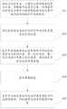
图2为本发明量块位姿测量原理示意图;图2(a)标定量块位姿测量原理示意图;图2(b)被测量块位姿测量原理示意图;Figure 2 is a schematic diagram of the measuring principle of the measuring block pose of the present invention; Figure 2 (a) is a schematic diagram of the measuring principle of the measuring block's pose; Figure 2 (b) is a schematic diagram of the measuring principle of the measuring block's pose;
图3为本发明一种机械臂运动学参数标定方法的整体流程图;3 is an overall flow chart of a method for calibrating kinematic parameters of a robotic arm according to the present invention;
图4为本发明一种机械臂运动学参数标定方法的具体实施装置图;FIG. 4 is a specific implementation device diagram of a method for calibrating kinematic parameters of a robotic arm according to the present invention;
图5为本发明标定装置初始化示意图;Fig. 5 is the initialization schematic diagram of the calibration device of the present invention;
图6为本发明一种机械臂运动学参数标定系统的结构示意图。FIG. 6 is a schematic structural diagram of a kinematic parameter calibration system of a robotic arm according to the present invention.
具体实施方式Detailed ways
下面将结合本发明实施例中的附图,对本发明实施例中的技术方案进行清楚、完整地描述,显然,所描述的实施例仅仅是本发明一部分实施例,而不是全部的实施例。基于本发明中的实施例,本领域普通技术人员在没有做出创造性劳动前提下所获得的所有其他实施例,都属于本发明保护的范围。The technical solutions in the embodiments of the present invention will be clearly and completely described below with reference to the accompanying drawings in the embodiments of the present invention. Obviously, the described embodiments are only a part of the embodiments of the present invention, but not all of the embodiments. Based on the embodiments of the present invention, all other embodiments obtained by those of ordinary skill in the art without creative efforts shall fall within the protection scope of the present invention.
本发明的目的是提供一种机械臂运动学参数标定方法及系统,以达到通用性好、低成本、高效率、可操作强的目的。The purpose of the present invention is to provide a method and system for calibrating kinematics parameters of a mechanical arm, so as to achieve the goals of good versatility, low cost, high efficiency and strong operability.
为使本发明的上述目的、特征和优点能够更加明显易懂,下面结合附图和具体实施方式对本发明作进一步详细的说明。In order to make the above objects, features and advantages of the present invention more clearly understood, the present invention will be described in further detail below with reference to the accompanying drawings and specific embodiments.
实施例一Example 1
请参见图1,本实施例提供的一种机械臂运动学参数标定方法,包括:Referring to FIG. 1 , a method for calibrating kinematic parameters of a robotic arm provided in this embodiment includes:
步骤101:初始化标定装置,以确定位移传感器的零点位置,并根据所述零点位置,准确获得后续标定过程中位移传感器的安装位置与被测量块的被测平面的距离;所述标定装置是由六个位移传感器按照3-2-1六点定位方式组装的;所述被测量块为安装在待标定的机械臂末端上的量块。Step 101: Initialize the calibration device to determine the zero point position of the displacement sensor, and accurately obtain the distance between the installation position of the displacement sensor and the measured plane of the measured block in the subsequent calibration process according to the zero point position; the calibration device is composed of: The six displacement sensors are assembled according to the 3-2-1 six-point positioning method; the measured block is a gauge block installed on the end of the robotic arm to be calibrated.
步骤102:确定被测量块坐标系相对于所述标定装置坐标系的位姿;所述被测量块坐标系是在所述被测量块移至所述标定装置的测量范围后确定的。Step 102: Determine the pose of the coordinate system of the measured block relative to the coordinate system of the calibration device; the coordinate system of the measured block is determined after the measured block is moved to the measurement range of the calibration device.
步骤103:基于所述被测量块坐标系相对于所述标定装置坐标系的位姿、第一定位偏差、第二定位偏差以及第三定位偏差,确定标定系统的运动学误差模型;所述标定系统为闭环系统;所述第一定位偏差为第一名义位姿与第一实际位姿之间的偏差;所述第一名义位姿为被测量块坐标系相对于机械臂末端坐标系的名义位姿,所述第一实际位姿为所述被测量块坐标系相对于机械臂末端坐标系的实际位姿;所述第二定位偏差为第二名义位姿与第二实际位姿之间的偏差,所述第二名义位姿为机械臂机座坐标系相对于标定装置坐标系的名义位姿,所述第二实际位姿为机械臂机座坐标系相对于标定装置坐标系的实际位姿;所述第三定位偏差为第三名义位姿与第三实际位姿之间的偏差;所述第三名义位姿为机械臂末端坐标系相对于机械臂机座坐标系的名义位姿;所述第三实际位姿为机械臂末端坐标系相对于机械臂机座坐标系的实际位姿;所述机械臂末端为待标定的机械臂末端,所述机械臂机座为待标定的机械臂机座。Step 103: Determine the kinematic error model of the calibration system based on the pose, the first positioning deviation, the second positioning deviation and the third positioning deviation of the coordinate system of the measured block relative to the coordinate system of the calibration device; the calibration The system is a closed-loop system; the first positioning deviation is the deviation between the first nominal pose and the first actual pose; the first nominal pose is the nominal value of the coordinate system of the measured block relative to the coordinate system of the end of the manipulator pose, the first actual pose is the actual pose of the coordinate system of the measured block relative to the coordinate system of the end of the manipulator; the second positioning deviation is the difference between the second nominal pose and the second actual pose the deviation of pose; the third positioning deviation is the deviation between the third nominal pose and the third actual pose; the third nominal pose is the nominal position of the coordinate system of the end of the manipulator relative to the coordinate system of the base of the manipulator The third actual pose is the actual pose of the coordinate system of the end of the manipulator relative to the coordinate system of the base of the manipulator; the end of the manipulator is the end of the manipulator to be calibrated, and the base of the manipulator is the end of the manipulator to be calibrated robot arm base.
步骤104:获取测量数据;所述测量数据包括多组位移传感器采集的测量值以及每组所述测量值对应的待标定的机械臂的关节角度。Step 104: Acquire measurement data; the measurement data includes measurement values collected by multiple sets of displacement sensors and joint angles of the robotic arm to be calibrated corresponding to each set of measurement values.
步骤105:基于所述标定系统的运动学误差模型和所述测量数据,对机械臂运动学参数进行标定。Step 105: Based on the kinematic error model of the calibration system and the measurement data, calibrate the kinematic parameters of the robotic arm.
本实施例提供的机械臂运动学参数标定方法的各个步骤具体描述如下:Each step of the method for calibrating the kinematic parameters of the robotic arm provided in this embodiment is specifically described as follows:
在执行步骤101之前,还包括:Before executing
安装标定装置以及待标定机械臂,具体为:Install the calibration device and the robotic arm to be calibrated, specifically:
首先将机械臂安装于标定平台,然后为了确定机械臂末端的位姿,在机械臂的末端通过机械连接方式安装被测量块,从而组装完成待标定机械臂。First install the manipulator on the calibration platform, and then in order to determine the pose of the end of the manipulator, install the measured block at the end of the manipulator by mechanical connection, so as to assemble the manipulator to be calibrated.
通过测量被测量块的空间位姿以获得机械臂末端的定位偏差。The positioning deviation of the end of the manipulator is obtained by measuring the spatial pose of the measured block.
为了测量机械臂末端的被测量块,需要设计一套标定装置;该标定装置主要由六个位移传感器按照3-2-1六点定位方式组装而成,故本实施例是通过3-2-1六点定位方式测量被测量块的位姿。In order to measure the measured block at the end of the manipulator, a calibration device needs to be designed; the calibration device is mainly composed of six displacement sensors assembled according to the 3-2-1 six-point positioning method, so this embodiment is based on the 3-2- 1. The six-point positioning method measures the pose of the measured block.
步骤101,具体包括:标定装置以及待标定机械臂安装完毕后,需要对标定装置进行初始化,以使得标定装置更为准确。Step 101 specifically includes: after the calibration device and the robotic arm to be calibrated are installed, the calibration device needs to be initialized to make the calibration device more accurate.
在标定装置初始化过程中,需要使用和待标定机械臂中机械臂末端相同规格的被测量块,即标定量块,进行初始化。将标定量块通过机械连接方式安装至标定装置上,根据机械结构的几何尺寸,可以确定标定量块相对于标定装置的位姿关系,同时也可确定当前位移传感器测头的安装位置距离当前被测量块表面(即被测平面)的距离,定义当前的距离为d=[d1 d2 d3 d4 d5 d6],同时可设置当前位移传感器为初始位置,将其设置为零位,进而确定标定装置坐标系。In the initialization process of the calibration device, it is necessary to use the measured block of the same specification as the end of the manipulator in the manipulator to be calibrated, that is, the calibration block, for initialization. The calibration block is installed on the calibration device by mechanical connection. According to the geometric size of the mechanical structure, the position and attitude relationship of the calibration block relative to the calibration device can be determined, and the distance between the installation position of the current displacement sensor probe can also be determined. Measure the distance of the block surface (that is, the plane to be measured), define the current distance as d=[d1 d2 d3 d4 d5 d6 ], and set the current displacement sensor as the initial position and set it to zero , and then determine the coordinate system of the calibration device.
步骤102,具体包括:Step 102 specifically includes:
标定装置初始化后,拆卸标定装置上的标定量块以便后续标定过程中测量机械臂末端上的被测量块的位姿。After the calibration device is initialized, the calibration block on the calibration device is disassembled to measure the pose of the measured block on the end of the robotic arm in the subsequent calibration process.
在初步建立标定系统的运动学模型前,首先需要设置一组机械臂的关节位形,即将机械臂末端上的被测量块移至标定装置的测量范围内;其次,基于位移传感器的伸缩量Δd=[Δd1 Δd2 Δd3 Δd4 Δd5 Δd6],构建被测量块坐标系,以便确定机械臂末端上的被测量块坐标系相对于标定装置坐标系的位姿为
量块位姿测量原理如图2所示,基于标定装置坐标系上的位移传感器的安装位置为Mki=[MkxiMkyiMkzi],测量方向为Mvi=[MvxiMvyiMvzi],其中,下标i表示第i个位移传感器,确定每个位移传感器基于标定装置坐标系下的空间直线方程为:The measurement principle of the gauge block pose is shown in Figure 2. The installation position of the displacement sensor on the coordinate system of the calibration device isM ki =[M kxiM kyiM kzi ], and the measurement direction isM vi =[M vxiM vyiM vzi ], where the subscript i represents the ith displacement sensor, and the spatial straight line equation determined for each displacement sensor based on the calibration device coordinate system is:

其中,li代表第i个直线上的点到位移传感器安装位置的距离。Among them, li represents the distance from the point on thei -th straight line to the installation position of the displacement sensor.
对于被测量块,基于被测量块坐标系,确定被测平面(被测量块所在平面)的法向向量为Lhi=[LhxiLhyiLhzi],确定过被测平面上任意一点的位置矢量为Lqi=[LqxiLqyiLqzi],现将方向向量(即法向向量)与位置矢量转化到标定装置坐标系下,具体为:For the measured block, based on the measured block coordinate system, the normal vector of the measured plane (the plane where the measured block is located) is determined asL hi =[L hxiL hyiL hzi ], and it is determined that on the measured plane The position vector of any point isL qi =[L qxiL qyiL qzi ], and now the direction vector (that is, the normal vector) and the position vector are transformed into the calibration device coordinate system, specifically:


进而确定被测量块的被测平面方程为:Then determine the measured plane equation of the measured block as:
([x y z]T-Mqi)·Mhi=0 i=1,2,...,6 (4);([xyz]T -M qi ) ·M hi = 0 i = 1, 2, . . . , 6 (4);
基于被测量块的当前位姿,通过位移传感器的测量值即可确定位移传感器的安装位置与被测平面之间的测量距离,其计算公式,为:Based on the current pose of the measured block, the measurement distance between the installation position of the displacement sensor and the measured plane can be determined by the measurement value of the displacement sensor. The calculation formula is:
li=di+Δdi i=1,2,...,6 (5);li =di +Δdi i =1,2,...,6 (5);
根据测量距离和被测平面方程,可建立以下方程:From the measured distance and the measured plane equation, the following equations can be established:

结合以上公式(1)~(6),可建立位移传感器安装位置距被测平面的距离与被测量块相对于标定装置的位姿之间的关系为:Combining the above formulas (1) to (6), the relationship between the distance between the installation position of the displacement sensor and the measured plane and the pose of the measured block relative to the calibration device can be established as follows:

其中,s是关于距离与位姿的非线性函数,


步骤103具体包括:Step 103 specifically includes:
基于步骤102,可实现通过标定装置测量被测量块的位姿信息,因此为初步确定标定系统的运动学模型以及数据采集奠定了基础。根据标定系统的闭环关系,可建立标定系统的运动学模型为:Based on

其中,


在标定装置的测量范围内,通过设置一组机械臂关节位形,即可根据步骤102确定被测量块坐标系相对于标定装置坐标系的位姿


其中,xr表示机械臂的关节角度,g代表机械臂的正运动学方程。由于机械臂受机械加工误差、装配误差、零部件磨损、末端负载变化以及温度的影响,直接导致机械臂名义的D-H参数pn与实际的D-H参数pa(下标a代表实际值)存在偏差Δp。因此,机械臂末端相对机械臂机座的实际位姿为:Among them, xr represents the joint angle of the manipulator, and g represents the forward kinematic equation of the manipulator. Since the manipulator is affected by machining errors, assembly errors, component wear, end load changes and temperature, there is a direct deviation between the nominal DH parameter pn of the manipulator and the actual DH parameter pa (subscript a represents the actual value). Δp. Therefore, the actual pose of the end of the manipulator relative to the base of the manipulator is:

同时由于被测量块存在安装误差,导致被测量块坐标系相对于机械臂末端坐标系的名义位姿


根据当前的名义值


机械臂机座坐标系相对于标定装置坐标系的名义位姿


通过以上分析,可构建标定系统的运动学误差模型为:Through the above analysis, the kinematic error model of the calibration system can be constructed as:

从运动学误差模型可观测出需通过标定方式求得

步骤104,具体包括:Step 104 specifically includes:
基于步骤103,在确定标定系统的运动学误差模型后,需要进行数据采集,为后续机械臂运动学参数标定做准备。具体操作如下:在标定装置的测量范围内,随机移动待标定的机械臂,通过标定装置即可测量机械臂末端上被测量块的位姿
步骤105具体包括:Step 105 specifically includes:
通过步骤104所采集到的数据,可对标定系统的运动学参数误差


其中,k表示采集的数据组数,f表示根据公式(14)转化的标定系统的运动学误差模型,

本实施例提供的机械臂运动学参数标定方法,还包括通过机械臂随机运动,以验证运动学参数标定结果的可靠性。为了表明本发明实施例的有效性,需要重新进行数据采集,在采集数据的同时,应尽量避免采集与标定过程一致的数据,对比标定前后的定位偏差是否得到明显的提升。The method for calibrating the kinematic parameters of the manipulator provided in this embodiment further includes random motion of the manipulator to verify the reliability of the kinematic parameter calibration result. In order to demonstrate the effectiveness of the embodiment of the present invention, data collection needs to be performed again. While collecting data, it is necessary to avoid collecting data consistent with the calibration process as much as possible, and compare whether the positioning deviation before and after calibration is significantly improved.
由于采用上述方案,本发明的优势有以下方面:在本发明中,所述方法具有较强的通用性,不限定机械臂自由度数目以及机械臂的类型,能够普遍应用于市场上任意类型的机械臂;该标定方法明显降低了标定的成本,并且保证了标定的精度,有利于市场的推广;同时在标定过程中不需要人工反复示教到达特定的目标位置,允许在标定装置的测量范围内随机移动机械臂以测量机械臂末端的被测量块,因此该标定方法明显提高了标定效率,增强了可操作度。Due to the adoption of the above scheme, the advantages of the present invention are as follows: In the present invention, the method has strong versatility, does not limit the number of degrees of freedom of the manipulator and the type of the manipulator, and can be generally applied to any type of robot on the market. Robotic arm; this calibration method significantly reduces the cost of calibration, and ensures the accuracy of the calibration, which is beneficial to the promotion of the market; at the same time, it does not require manual repeated teaching to reach a specific target position during the calibration process, allowing the measurement range of the calibration device. The robot arm is randomly moved inside to measure the measured block at the end of the robot arm, so this calibration method significantly improves the calibration efficiency and enhances the operability.
实施例二Embodiment 2
本实施例提供的机械臂运动学参数标定方法,请参见图3,包括:The method for calibrating the kinematic parameters of the manipulator provided in this embodiment is shown in Fig. 3, including:
步骤110、安装机械臂标定装置以及待标定的机械臂。
参照图4,本实施例是对UR10机械臂的运动学参数进行标定。为了验证该方法的有效性,将标定装置以及待标定机械臂安装于三坐标测量仪上,在对机械臂运动学参数标定后,通过三坐标测量仪进行验证。Referring to FIG. 4 , in this embodiment, the kinematic parameters of the UR10 robotic arm are calibrated. In order to verify the effectiveness of the method, the calibration device and the manipulator to be calibrated are installed on the CMM, and the kinematic parameters of the manipulator are calibrated and verified by the CMM.
步骤120、初始化机械臂标定装置。
参照图5,在机械臂标定装置对机械臂末端量块进行测量前,需要对该装置进行初始化。在该过程中,需要使用和机械臂末端相同规格的量块进行初始化。将标定量块通过机械连接安装至标定装置上,根据机械结构的几何尺寸,可确定当前位移传感器测头安装位置距离当前被测量块表面的距离为(本实施例使用的距离单位为mm):d=[30 30 30 30 3030](16)。同时可设置当前位移传感器为初始位置,将其设置为零位。Referring to FIG. 5 , before the robot arm calibration device measures the gauge block at the end of the robot arm, the device needs to be initialized. In this process, it is necessary to use the gauge block of the same specification as the end of the robot arm for initialization. Install the calibration block on the calibration device through a mechanical connection. According to the geometric size of the mechanical structure, the distance between the current displacement sensor probe installation position and the current surface of the block to be measured can be determined as (the distance unit used in this embodiment is mm): d=[30 30 30 30 3030](16). At the same time, the current displacement sensor can be set as the initial position and set to zero.
步骤130、测量机械臂末端量块位姿。
在初始化机械臂标定装置后,拆卸标定装置的量块。在初步建立标定系统的运动学模型前,将机械臂末端量块移至标定装置的测量范围内,基于位移传感器的伸缩量确定机械臂末端量块坐标系相对于标定装置坐标系的位姿。在该实例中,基于标定装置坐标系位移传感器的安装位置如表1所示,测量方向如表2所示。对于被测量块,基于被测量块坐标系,被测量块的平面法向向量如表3所示,过平面上任意一点的位置矢量如表4所示。当前机械臂关节位形为(本发明使用的关节角度单位为°):After initializing the robotic arm calibration device, remove the gauge block of the calibration device. Before initially establishing the kinematics model of the calibration system, move the gauge block at the end of the manipulator to the measurement range of the calibration device, and determine the pose of the coordinate system of the gauge block at the end of the manipulator relative to the coordinate system of the calibration device based on the expansion and contraction of the displacement sensor. In this example, the installation position of the displacement sensor based on the calibration device coordinate system is shown in Table 1, and the measurement direction is shown in Table 2. For the measured block, based on the measured block coordinate system, the plane normal vector of the measured block is shown in Table 3, and the position vector passing through any point on the plane is shown in Table 4. The current joint configuration of the robot arm is (the joint angle unit used in the present invention is °):
xr=[-80.129 -52.586 110.921 124.318 -101.660 -89.995](17)。xr =[-80.129-52.586 110.921 124.318-101.660-89.995](17).
基于当前六个位移传感器的伸缩量为:The expansion and contraction amount based on the current six displacement sensors is:
Δd=[4.227 2.597 2.844 2.662 2.032 3.969] (18)。Δd=[4.227 2.597 2.844 2.662 2.032 3.969] (18).
即可确定六个位移传感器的安装位置距离测量面的距离为:It can be determined that the distance between the installation position of the six displacement sensors and the measurement surface is:
l=[34.227 32.597 32.844 32.662 32.032 33.969] (19)。l=[34.227 32.597 32.844 32.662 32.032 33.969] (19).
因此,可求得机械臂末端量块坐标系相对于标定装置坐标系的位姿为:Therefore, the pose of the coordinate system of the gage block at the end of the manipulator relative to the coordinate system of the calibration device can be obtained as:

步骤140、初步确定标定系统的运动学模型与误差模型。Step 140: Preliminarily determine a kinematic model and an error model of the calibration system.
基于步骤130当前机械臂的关节角度,根据机械臂名义D-H参数即可求出机械臂末端坐标系相对机械臂机座坐标系的名义位姿为:Based on the joint angle of the current manipulator in

根据机械连接件的几何关系可确定机械臂末端坐标系相对机械臂机座坐标系的名义位姿为:According to the geometric relationship of the mechanical connector, the nominal pose of the coordinate system of the end of the manipulator relative to the coordinate system of the base of the manipulator can be determined as:

根据当前的名义值


代入上述数据,即可求得:Substituting the above data, you can get:

步骤150、数据采集。
在初步确定各个坐标系之间的名义位姿后,需要进行数据采集,即在标定装置的测量范围内,随机移动机械臂,通过标定装置可测得机械臂末端量块的位姿,在该组实体实验中共采集了16组数据,其中机械臂末端量块相对于标定装置的位姿如表5所示,同时记录机械臂所对应的关节角度如表6所示。After the nominal pose between each coordinate system is initially determined, data collection is required, that is, within the measurement range of the calibration device, the manipulator is moved randomly, and the pose of the gauge block at the end of the manipulator can be measured through the calibration device. A total of 16 groups of data were collected in the group entity experiment, in which the pose of the gage block at the end of the robotic arm relative to the calibration device is shown in Table 5, and the joint angles corresponding to the robotic arm are recorded as shown in Table 6.
步骤160、对机械臂运动学参数进行标定。
在进行大量的数据采集后,需要对系统的运动学参数误差进行标定,即可确定机械臂运动学参数。基于上述步骤150,将采集的数据代入目标优化函数中,通过迭代优化可求得系统的运动学参数误差,表7为机械臂机座坐标系相对于标定装置坐标系的位姿误差,表8为机械臂D-H参数的误差,表9为机械臂末端量块相对于机械臂末端坐标系的安装误差,根据上述标定的参数误差进而可获得标定后机械臂运动学参数。After a large amount of data collection, the kinematic parameter error of the system needs to be calibrated, and then the kinematic parameters of the manipulator can be determined. Based on the
步骤170、验证运动学参数标定结果的可靠性。Step 170: Verify the reliability of the kinematic parameter calibration result.
在对机械臂运动学参数进行标定后,需要验证运动学参数标定结果的可靠性。为了表明本发明的有效性,需要重新进行数据采集,在采集数据的同时,应尽量避免采集与标定过程一致的数据,对比标定前后的定位偏差是否得到明显的提升。由于机械臂末端量块的位姿无法通过外界其他设备直接获得,因此使用三坐标测量仪测量机械臂在两个不同位形空间下机械臂末端的相对距离,如表10所示。After calibrating the kinematic parameters of the manipulator, it is necessary to verify the reliability of the kinematic parameter calibration results. In order to demonstrate the effectiveness of the present invention, data collection needs to be performed again. While collecting data, it is necessary to avoid collecting data consistent with the calibration process as much as possible, and compare whether the positioning deviation before and after calibration is significantly improved. Since the pose of the gage block at the end of the manipulator cannot be directly obtained by other external devices, a three-coordinate measuring instrument is used to measure the relative distance of the manipulator end of the manipulator in two different configuration spaces, as shown in Table 10.
表1.安装位置表Table 1. Mounting Location Table

表2.测量方向表Table 2. Measurement Direction Table

表3.量块平面法向向量表Table 3. Gage block plane normal vector table

表4.量块位置矢量表Table 4. Gage block position vector table

表5.量块相对于标定装置的位姿表Table 5. Pose table of the gauge block relative to the calibration device


表6.机械臂关节角度表Table 6. Manipulator joint angle table


表7.机械臂机座坐标系相对于标定装置坐标系的位姿误差表Table 7. The pose error table of the coordinate system of the robot arm frame relative to the coordinate system of the calibration device

表8.机械臂D-H参数误差表Table 8. D-H parameter error table of robot arm

表9.机械臂末端量块相对于机械臂末端坐标系的安装误差表Table 9. Installation error table of the gage block at the end of the robot arm relative to the coordinate system of the end of the robot arm

表10.两位形之间机械臂末端的相对距离表Table 10. Relative distance table of the end of the robot arm between the two shapes


实施例三Embodiment 3
请参见图6,本实施例提供的一种机械臂运动学参数标定系统包括:Referring to FIG. 6 , a system for calibrating kinematic parameters of a robotic arm provided in this embodiment includes:
初始化模块601,用于初始化标定装置,以确定位移传感器的零点位置,并根据所述零点位置,准确获得后续标定过程中位移传感器的安装位置与被测量块的被测平面的距离;所述标定装置是由六个位移传感器按照3-2-1六点定位方式组装的;所述被测量块为安装在待标定的机械臂末端上的量块。The
位姿确定模块602,用于确定被测量块坐标系相对于所述标定装置坐标系的位姿;所述被测量块坐标系是在所述被测量块移至所述标定装置的测量范围后确定的。The
运动学误差模型确定模块603,用于基于所述被测量块坐标系相对于所述标定装置坐标系的位姿、第一定位偏差、第二定位偏差以及第三定位偏差,确定标定系统的运动学误差模型;所述标定系统为闭环系统;所述第一定位偏差为第一名义位姿与第一实际位姿之间的偏差;所述第一名义位姿为被测量块坐标系相对于机械臂末端坐标系的名义位姿,所述第一实际位姿为所述被测量块坐标系相对于机械臂末端坐标系的实际位姿;所述第二定位偏差为第二名义位姿与第二实际位姿之间的偏差,所述第二名义位姿为机械臂机座坐标系相对于标定装置坐标系的名义位姿,所述第二实际位姿为机械臂机座坐标系相对于标定装置坐标系的实际位姿;所述第三定位偏差为第三名义位姿与第三实际位姿之间的偏差;所述第三名义位姿为机械臂末端坐标系相对于机械臂机座坐标系的名义位姿;所述第三实际位姿为机械臂末端坐标系相对于机械臂机座坐标系的实际位姿;所述机械臂末端为待标定的机械臂末端,所述机械臂机座为待标定的机械臂机座。The kinematic error
数据获取模块604,用于获取测量数据;所述测量数据包括多组位移传感器采集的测量值以及每组所述测量值对应的待标定的机械臂的关节角度。The
标定模块605,用于基于所述标定系统的运动学误差模型和所述测量数据,对机械臂运动学参数进行标定。The
所述初始化模块601,具体包括:The
初始化单元,用于将标定量块通过机械连接方式安装至所述标定装置上,并根据机械结构的几何尺寸,确定标定量块相对于标定装置的位姿关系,以及位移传感器安装位置到达被测平面的距离,并设置当前位移传感器的测量值为零,进而可以准确获得后续标定过程中位移传感器的安装位置与被测平面的距离;所述标定量块为与所述被测量块相同规格的量块。The initialization unit is used to install the calibration block on the calibration device through mechanical connection, and according to the geometric size of the mechanical structure, determine the pose relationship of the calibration block relative to the calibration device, and the installation position of the displacement sensor reaches the measured The distance between the plane and the measured value of the current displacement sensor is set to zero, so that the distance between the installation position of the displacement sensor and the measured plane in the subsequent calibration process can be accurately obtained; the calibration block is of the same specification as the measured block. Gauge block.
所述位姿确定模块602,具体包括:The
测量块坐标系构建单元,用于构建被测量块坐标系。The measuring block coordinate system construction unit is used to construct the measured block coordinate system.
空间直线方程确定单元,用于基于所述标定装置坐标系上的位移传感器的安装位置和测量方向,确定每个位移传感器基于所述标定装置坐标系下的空间直线方程。The space straight line equation determination unit is configured to determine, based on the installation position and measurement direction of the displacement sensors on the calibration device coordinate system, the space straight line equation of each displacement sensor based on the calibration device coordinate system.
被测平面方程确定单元,用于基于所述标定装置坐标系和所述被测量块坐标系,确定所述被测量块的被测平面方程;所述被测平面为所述被测量块所在平面。A measured plane equation determination unit, configured to determine the measured plane equation of the measured block based on the coordinate system of the calibration device and the measured block coordinate system; the measured plane is the plane where the measured block is located .
测量距离确定单元,用于基于所述空间直线方程和所述位移传感器的测量值,确定每个所述位移传感器的安装位置与所述被测平面之间的测量距离。A measurement distance determination unit, configured to determine the measurement distance between the installation position of each of the displacement sensors and the measured plane based on the space straight line equation and the measurement value of the displacement sensor.
位姿确定单元,用于基于所述被测平面方程和所述测量距离,确定被测量块坐标系相对于所述标定装置坐标系的位姿。A pose determination unit, configured to determine the pose of the coordinate system of the measured block relative to the coordinate system of the calibration device based on the measured plane equation and the measured distance.
其中,所述被测平面方程确定单元,具体包括:Wherein, the measured plane equation determination unit specifically includes:
法向向量和位置矢量确定子单元,用于基于所述被测量块坐标系,确定被测平面的法向向量以及过所述被测平面上任意一点的位置矢量。The normal vector and position vector determination subunit is used for determining the normal vector of the measured plane and the position vector passing through any point on the measured plane based on the coordinate system of the measured block.
被测平面方程确定子单元,用于将所述法向向量与所述位置矢量均转化到所述标定装置坐标系下,确定所述被测量块的被测平面方程。The measured plane equation determination subunit is configured to convert both the normal vector and the position vector into the coordinate system of the calibration device to determine the measured plane equation of the measured block.
所述标定模块605,具体包括:The
标定单元,用于基于所述标定系统的运动学误差模型和所述测量数据,采用非线性迭代最小二乘方式,对机械臂运动学参数进行标定。The calibration unit is used for calibrating the kinematic parameters of the manipulator by adopting the nonlinear iterative least squares method based on the kinematic error model of the calibration system and the measurement data.
本发明提供了一种机械臂运动学参数标定方法及系统,其标定方法为闭环标定。通过设计一套标定转置,该标定装置主要使用了六个位移传感器,基于3-2-1六点定位方法以确定安装于机械臂末端量块的位姿,在建立好系统运动学误差模型后,通过最小二乘算法求解机械臂运动学参数误差。本发明的标定装置相比于开环标定而言,极大的降低了机械臂运动学参数的标定成本;相比于当前的闭环标定而言,不需要人工严格参照空间中的点、线、面等几何约束示教机械臂到达特定的目标位置,本发明的标定装置只需要将机械臂末端的量块移至位移传感器的测量范围,在位移传感器的测量范围内随机移动机械臂,因此明显提高了标定效率,增强了可操作度,本发明可应用于不同类型的机械臂运动学参数标定。综上所述,本发明提供了一套通用性好、低成本、高效率、可操作度强的机械臂运动学参数标定方法及系统,具有广泛的应用领域和应用前景。The invention provides a method and system for calibrating kinematic parameters of a mechanical arm, and the calibration method is closed-loop calibration. By designing a set of calibration transposition, the calibration device mainly uses six displacement sensors, based on the 3-2-1 six-point positioning method to determine the pose of the gauge block installed at the end of the manipulator, after establishing the system kinematic error model Then, the kinematic parameter error of the manipulator is solved by the least squares algorithm. Compared with the open-loop calibration, the calibration device of the present invention greatly reduces the calibration cost of the kinematic parameters of the manipulator; compared with the current closed-loop calibration, it does not need to strictly refer to the points, lines, and points in the space manually. The geometric constraints such as the surface are used to teach the manipulator to reach a specific target position. The calibration device of the present invention only needs to move the gauge block at the end of the manipulator to the measurement range of the displacement sensor, and move the manipulator randomly within the measurement range of the displacement sensor. Therefore, it is obvious The calibration efficiency is improved and the operability is enhanced, and the present invention can be applied to the calibration of kinematic parameters of different types of mechanical arms. To sum up, the present invention provides a set of method and system for calibrating kinematics parameters of a manipulator with good versatility, low cost, high efficiency and strong operability, and has a wide range of application fields and application prospects.
本说明书中各个实施例采用递进的方式描述,每个实施例重点说明的都是与其他实施例的不同之处,各个实施例之间相同相似部分互相参见即可。对于实施例公开的系统而言,由于其与实施例公开的方法相对应,所以描述的比较简单,相关之处参见方法部分说明即可。The various embodiments in this specification are described in a progressive manner, and each embodiment focuses on the differences from other embodiments, and the same and similar parts between the various embodiments can be referred to each other. For the system disclosed in the embodiment, since it corresponds to the method disclosed in the embodiment, the description is relatively simple, and the relevant part can be referred to the description of the method.
本文中应用了具体个例对本发明的原理及实施方式进行了阐述,以上实施例的说明只是用于帮助理解本发明的方法及其核心思想;同时,对于本领域的一般技术人员,依据本发明的思想,在具体实施方式及应用范围上均会有改变之处。综上所述,本说明书内容不应理解为对本发明的限制。In this paper, specific examples are used to illustrate the principles and implementations of the present invention. The descriptions of the above embodiments are only used to help understand the methods and core ideas of the present invention; meanwhile, for those skilled in the art, according to the present invention There will be changes in the specific implementation and application scope. In conclusion, the contents of this specification should not be construed as limiting the present invention.
Claims (10)
Translated fromChinesePriority Applications (1)
| Application Number | Priority Date | Filing Date | Title |
|---|---|---|---|
| CN202110968698.6ACN113618738B (en) | 2021-08-23 | 2021-08-23 | Mechanical arm kinematics parameter calibration method and system |
Applications Claiming Priority (1)
| Application Number | Priority Date | Filing Date | Title |
|---|---|---|---|
| CN202110968698.6ACN113618738B (en) | 2021-08-23 | 2021-08-23 | Mechanical arm kinematics parameter calibration method and system |
Publications (2)
| Publication Number | Publication Date |
|---|---|
| CN113618738Atrue CN113618738A (en) | 2021-11-09 |
| CN113618738B CN113618738B (en) | 2024-04-19 |
Family
ID=78387232
Family Applications (1)
| Application Number | Title | Priority Date | Filing Date |
|---|---|---|---|
| CN202110968698.6AActiveCN113618738B (en) | 2021-08-23 | 2021-08-23 | Mechanical arm kinematics parameter calibration method and system |
Country Status (1)
| Country | Link |
|---|---|
| CN (1) | CN113618738B (en) |
Cited By (4)
| Publication number | Priority date | Publication date | Assignee | Title |
|---|---|---|---|---|
| CN113942622A (en)* | 2021-11-19 | 2022-01-18 | 博迈科海洋工程股份有限公司 | Motion compensation method suitable for FPSO upper module lifting installation process |
| CN115319726A (en)* | 2022-08-15 | 2022-11-11 | 中国科学院宁波材料技术与工程研究所 | A Robot Calibration Method Based on Position and Distance Constraints |
| CN117021113A (en)* | 2023-09-20 | 2023-11-10 | 苏州诺克汽车工程装备有限公司 | Mechanical arm cooperative positioning assembly method, system and medium |
| CN117140535A (en)* | 2023-10-27 | 2023-12-01 | 南湖实验室 | Robot kinematics parameter calibration method and system based on single measurement |
Citations (5)
| Publication number | Priority date | Publication date | Assignee | Title |
|---|---|---|---|---|
| CN107553493A (en)* | 2017-09-22 | 2018-01-09 | 东南大学 | A kind of robot kinematics' parameter calibration method based on displacement sensor for pull rope |
| CN109773786A (en)* | 2018-12-29 | 2019-05-21 | 南京埃斯顿机器人工程有限公司 | A kind of industrial robot plane precision scaling method |
| CN110281241A (en)* | 2019-06-27 | 2019-09-27 | 大连理工大学 | Mechanical arm kinematic calibration method is measured based on laser tracker |
| CN111590566A (en)* | 2020-05-12 | 2020-08-28 | 北京控制工程研究所 | On-orbit calibration method for kinematic parameters of fully-configured space manipulator |
| CN112847341A (en)* | 2020-12-25 | 2021-05-28 | 中国科学院宁波材料技术与工程研究所 | Industrial robot step-by-step calibration system and method |
- 2021
- 2021-08-23CNCN202110968698.6Apatent/CN113618738B/enactiveActive
Patent Citations (5)
| Publication number | Priority date | Publication date | Assignee | Title |
|---|---|---|---|---|
| CN107553493A (en)* | 2017-09-22 | 2018-01-09 | 东南大学 | A kind of robot kinematics' parameter calibration method based on displacement sensor for pull rope |
| CN109773786A (en)* | 2018-12-29 | 2019-05-21 | 南京埃斯顿机器人工程有限公司 | A kind of industrial robot plane precision scaling method |
| CN110281241A (en)* | 2019-06-27 | 2019-09-27 | 大连理工大学 | Mechanical arm kinematic calibration method is measured based on laser tracker |
| CN111590566A (en)* | 2020-05-12 | 2020-08-28 | 北京控制工程研究所 | On-orbit calibration method for kinematic parameters of fully-configured space manipulator |
| CN112847341A (en)* | 2020-12-25 | 2021-05-28 | 中国科学院宁波材料技术与工程研究所 | Industrial robot step-by-step calibration system and method |
Non-Patent Citations (2)
| Title |
|---|
| YING LIU等: "Improvement of Robot Accuracy with an Optical Tracking System", 《SENSORS》, vol. 20, no. 21, pages 1 - 24* |
| 庄正浩: "基于闭环测量的机器人关节刚度标定方法", 《计量与测试技术》, vol. 48, no. 7, pages 59 - 62* |
Cited By (7)
| Publication number | Priority date | Publication date | Assignee | Title |
|---|---|---|---|---|
| CN113942622A (en)* | 2021-11-19 | 2022-01-18 | 博迈科海洋工程股份有限公司 | Motion compensation method suitable for FPSO upper module lifting installation process |
| CN113942622B (en)* | 2021-11-19 | 2023-11-07 | 博迈科海洋工程股份有限公司 | Motion compensation method suitable for FPSO upper module lifting and installing process |
| CN115319726A (en)* | 2022-08-15 | 2022-11-11 | 中国科学院宁波材料技术与工程研究所 | A Robot Calibration Method Based on Position and Distance Constraints |
| CN117021113A (en)* | 2023-09-20 | 2023-11-10 | 苏州诺克汽车工程装备有限公司 | Mechanical arm cooperative positioning assembly method, system and medium |
| CN117021113B (en)* | 2023-09-20 | 2024-03-19 | 苏州诺克智能装备股份有限公司 | Mechanical arm cooperative positioning assembly method, system and medium |
| CN117140535A (en)* | 2023-10-27 | 2023-12-01 | 南湖实验室 | Robot kinematics parameter calibration method and system based on single measurement |
| CN117140535B (en)* | 2023-10-27 | 2024-02-02 | 南湖实验室 | Robot kinematics parameter calibration method and system based on single measurement |
Also Published As
| Publication number | Publication date |
|---|---|
| CN113618738B (en) | 2024-04-19 |
Similar Documents
| Publication | Publication Date | Title |
|---|---|---|
| CN113618738B (en) | Mechanical arm kinematics parameter calibration method and system | |
| CN111660295B (en) | Industrial robot absolute precision calibration system and calibration method | |
| CN107042528B (en) | Kinematics calibration system and method for industrial robot | |
| CN109822574B (en) | A method for calibrating a six-dimensional force sensor at the end of an industrial robot | |
| CN110757504B (en) | Positioning error compensation method of high-precision movable robot | |
| CN107421442B (en) | An Online Compensation Method for Robot Positioning Error Aided by External Measurement | |
| CN110802585B (en) | Mechanical arm tail end sensor compensation method and contact force/moment measurement method | |
| CN110281241A (en) | Mechanical arm kinematic calibration method is measured based on laser tracker | |
| CN111203861B (en) | Calibration method and calibration system for robot tool coordinate system | |
| CN106777656B (en) | A PMPSD-based Absolute Precision Calibration Method for Industrial Robots | |
| CN110253574B (en) | Multi-task mechanical arm pose detection and error compensation method | |
| CN107443382A (en) | Industrial robot structure parameter error recognizes and compensation method | |
| CN112318498A (en) | Industrial robot calibration method considering parameter coupling | |
| CN108406771A (en) | A kind of plane restriction error model and robot self-calibrating method | |
| CN106052555A (en) | Industrial robot base coordinate measuring method | |
| CN113146613B (en) | An industrial robot D-H parameter three-dimensional self-calibration calibration device and method | |
| CN107478183B (en) | Tandem type robot kinematics' parameter calibration method based on the sampling of multiple spot posture | |
| WO2018196232A1 (en) | Method for automatically calibrating robot and end effector, and system | |
| JP2011224672A (en) | Deriving method and calibration method for tool vector of robot | |
| CN114754672B (en) | A method for determining the coordinate transformation relationship between a robot and a measuring instrument | |
| JP5378908B2 (en) | Robot accuracy adjustment method and robot | |
| CN113211445A (en) | Robot parameter calibration method, device, equipment and storage medium | |
| CN115674171A (en) | Robot pose measurement and compensation method and system, control device, storage medium | |
| CN115371564B (en) | Method and system for calibrating relative pose between line laser sensor and robot flange | |
| CN113733155A (en) | Six-axis industrial robot calibration device and calibration method |
Legal Events
| Date | Code | Title | Description |
|---|---|---|---|
| PB01 | Publication | ||
| PB01 | Publication | ||
| SE01 | Entry into force of request for substantive examination | ||
| SE01 | Entry into force of request for substantive examination | ||
| GR01 | Patent grant | ||
| GR01 | Patent grant |