CN113607605A - System and method for rapidly collecting ions in water - Google Patents
System and method for rapidly collecting ions in waterDownload PDFInfo
- Publication number
- CN113607605A CN113607605ACN202110934951.6ACN202110934951ACN113607605ACN 113607605 ACN113607605 ACN 113607605ACN 202110934951 ACN202110934951 ACN 202110934951ACN 113607605 ACN113607605 ACN 113607605A
- Authority
- CN
- China
- Prior art keywords
- dgt
- electric field
- sampler
- ions
- parallel electric
- Prior art date
- Legal status (The legal status is an assumption and is not a legal conclusion. Google has not performed a legal analysis and makes no representation as to the accuracy of the status listed.)
- Granted
Links
Images


Classifications
- G—PHYSICS
- G01—MEASURING; TESTING
- G01N—INVESTIGATING OR ANALYSING MATERIALS BY DETERMINING THEIR CHEMICAL OR PHYSICAL PROPERTIES
- G01N13/00—Investigating surface or boundary effects, e.g. wetting power; Investigating diffusion effects; Analysing materials by determining surface, boundary, or diffusion effects
- G—PHYSICS
- G01—MEASURING; TESTING
- G01N—INVESTIGATING OR ANALYSING MATERIALS BY DETERMINING THEIR CHEMICAL OR PHYSICAL PROPERTIES
- G01N1/00—Sampling; Preparing specimens for investigation
- G01N1/02—Devices for withdrawing samples
- G01N1/10—Devices for withdrawing samples in the liquid or fluent state
- G—PHYSICS
- G01—MEASURING; TESTING
- G01N—INVESTIGATING OR ANALYSING MATERIALS BY DETERMINING THEIR CHEMICAL OR PHYSICAL PROPERTIES
- G01N1/00—Sampling; Preparing specimens for investigation
- G01N1/28—Preparing specimens for investigation including physical details of (bio-)chemical methods covered elsewhere, e.g. G01N33/50, C12Q
- G01N1/34—Purifying; Cleaning
Landscapes
- Life Sciences & Earth Sciences (AREA)
- Health & Medical Sciences (AREA)
- General Health & Medical Sciences (AREA)
- Chemical & Material Sciences (AREA)
- Analytical Chemistry (AREA)
- Biochemistry (AREA)
- Physics & Mathematics (AREA)
- General Physics & Mathematics (AREA)
- Immunology (AREA)
- Pathology (AREA)
- Hydrology & Water Resources (AREA)
- Engineering & Computer Science (AREA)
- Biomedical Technology (AREA)
- Molecular Biology (AREA)
- Sampling And Sample Adjustment (AREA)
Abstract
Translated fromChinese
Description
Translated fromChinese技术领域technical field
本发明涉及梯度扩散薄膜技术领域,尤其涉及一种水中离子快速采集系统及方法。The invention relates to the technical field of gradient diffusion films, in particular to a system and method for fast collection of ions in water.
背景技术Background technique
梯度扩散薄膜(Diffusive Gradients in Thin-films,DGT)技术主要利用Fick第一扩散定律,通过研究元素在DGT扩散层的梯度扩散及其缓冲动力学过程,获得元素在环境介质中的有效态含量与空间分布、离子态- 络合态结合动力学以及固-液之间交换动力学的信息。DGT技术可以应用于沉积物的地球化学特征、水质的监测、待测离子在DGT与土壤界面的动力学过程和重金属的生物有效性等多方面研究。The gradient diffusion thin film (Diffusive Gradients in Thin-films, DGT) technology mainly uses Fick's first law of diffusion. Information on spatial distribution, ionic-complex binding kinetics, and solid-liquid exchange kinetics. DGT technology can be applied to the study of geochemical characteristics of sediments, monitoring of water quality, kinetic processes of ions to be measured at the interface between DGT and soil, and bioavailability of heavy metals.
现有的DGT装置由固定层和扩散层叠加组成,目标离子以自由扩散方式穿过扩散层,随即被固定膜捕获,并在扩散层形成线性梯度分布,整个吸附过程耗时久,采集效率低,难以在短时间完成水样采集。The existing DGT device is composed of a fixed layer and a diffusion layer. The target ions pass through the diffusion layer in a free diffusion manner, and are then captured by the fixed membrane, and form a linear gradient distribution in the diffusion layer. The entire adsorption process takes a long time and the collection efficiency is low. , it is difficult to complete the water sample collection in a short time.
另外,现有DGT装置在河流湖泊的投放和使用过程中,由于水流过急、水位变化过大等因素,导致DGT采样装置在水下的稳定性较差往往会发生丢失,而且采样深度无法调节,无法实现定深采样。In addition, in the process of putting and using the existing DGT devices in rivers and lakes, due to factors such as excessive water flow and excessive changes in water level, the DGT sampling device has poor underwater stability and is often lost, and the sampling depth cannot be adjusted. , the fixed depth sampling cannot be achieved.
发明内容SUMMARY OF THE INVENTION
鉴于上述的分析,本发明旨在提供一种水中离子快速采集系统及方法,用以解决现有水下DGT装置的采样耗时久、效率低以及在水中采样容易丢失的问题。In view of the above analysis, the present invention aims to provide a rapid collection system and method of ions in water to solve the problems of time-consuming, low-efficiency and easy-to-lost sampling of existing underwater DGT devices.
本发明的目的主要是通过以下技术方案实现的:The object of the present invention is mainly achieved through the following technical solutions:
一方面,提供一种水中离子快速采集系统,包括:In one aspect, a rapid collection system for ions in water is provided, including:
平行电场发生组件,被配置为产生稳定的平行电场;a parallel electric field generating component configured to generate a stable parallel electric field;
DGT采样器,DGT采样器置于平行电场内,DGT采样器的轴线平行于平行电场的电场线布置;DGT sampler, the DGT sampler is placed in the parallel electric field, and the axis of the DGT sampler is arranged parallel to the electric field lines of the parallel electric field;
框架,框架具有安装空间,以备安装DGT采样器和平行电场发生组件;Frame, the frame has installation space for the installation of DGT sampler and parallel electric field generating components;
固定机构,固定机构与框架可拆卸连接,以将DGT采样器和平行电场发生组件限定在指定水深位置。The fixing mechanism is detachably connected with the frame, so as to confine the DGT sampler and the parallel electric field generating assembly at a specified water depth position.
进一步地,固定机构包括承载座、连接箱、定深浮球和定位浮标;承载座的下方设有定位插杆,承载座的上部设有连接箱,连接箱内设有绕线组件,绕线组件上缠绕有第一连接绳,第一连接绳的一端与定深浮球连接;框架拆卸连接在第一连接绳上;定深浮球通过第二连接绳与定位浮标连接。Further, the fixing mechanism includes a bearing seat, a connecting box, a fixed-depth floating ball and a positioning buoy; a positioning insert rod is arranged below the bearing seat, a connecting box is arranged on the upper part of the bearing seat, and a winding assembly is arranged in the connecting box, and the winding A first connecting rope is wound on the component, and one end of the first connecting rope is connected with the fixed-depth floating ball; the frame is disassembled and connected to the first connecting rope; the fixed-depth floating ball is connected with the positioning buoy through the second connecting rope.
进一步地,DGT采样器包括同轴设置的第一DGT采样器与第二DGT 采样器。Further, the DGT sampler includes a first DGT sampler and a second DGT sampler that are coaxially arranged.
进一步地,平行电场发生组件包括阳极、阴极及直流电源;阳极与阴极平行设置,并分别与直流电源的正极和负极连接。Further, the parallel electric field generating assembly includes an anode, a cathode and a DC power source; the anode and the cathode are arranged in parallel and are respectively connected to the positive electrode and the negative electrode of the DC power source.
进一步地,DGT采样器包括外壳,外壳内同轴依次设置有过滤膜、扩散层和吸附层。Further, the DGT sampler includes a casing, and a filter membrane, a diffusion layer and an adsorption layer are arranged in the casing coaxially in sequence.
进一步地,第一DGT采样器的过滤膜与第二DGT采样器的过滤膜相对设置,第一DGT采样器的吸附层朝向阳极,第二DGT采样器的吸附层朝向阴极。Further, the filter membrane of the first DGT sampler is disposed opposite to the filter membrane of the second DGT sampler, the adsorption layer of the first DGT sampler faces the anode, and the adsorption layer of the second DGT sampler faces the cathode.
进一步地,第一DGT采样器的吸附层与第二DGT采样器的吸附层相对设置,第一DGT采样器的过滤膜朝向阳极,第二DGT采样器的过滤膜朝向阴极。Further, the adsorption layer of the first DGT sampler is disposed opposite to the adsorption layer of the second DGT sampler, the filter membrane of the first DGT sampler faces the anode, and the filter membrane of the second DGT sampler faces the cathode.
另一方面,提供一种水中离子快速采集方法,利用上述技术方案的水中离子快速采集系统。On the other hand, a method for rapidly collecting ions in water is provided, using the system for rapidly collecting ions in water according to the above technical solution.
进一步地,采集方法包括如下步骤:Further, the collection method includes the following steps:
将固定机构固定在水体中,利用平行电场发生组件在DGT采样器所在区域产生平行电场,DGT采样器的吸附层吸附水中金属元素。The fixing mechanism is fixed in the water body, and the parallel electric field generating component is used to generate a parallel electric field in the area where the DGT sampler is located, and the adsorption layer of the DGT sampler absorbs the metal elements in the water.
进一步地,按照以下公式计算DGT采样器的吸附层上待测金属元素吸附量MDGT:Further, calculate the adsorption amount of the metal element to be measured MDGT on the adsorption layer of the DGT sampler according to the following formula:

基于待测金属元素吸附量MDGT,按照以下公式计算溶液中待测离子浓度Cb:Based on the adsorption amount of the metal element to be measured MDGT , the concentration of the ion to be measured Cb in the solution is calculated according to the following formula:

其中,
与现有技术相比,本发明至少具有如下有益效果之一:Compared with the prior art, the present invention has at least one of the following beneficial effects:
1、通过在DGT采样器的吸附环境中加设平行电场中,以增加了水体中金属离子的迁移率,在相同时间内可以吸附更多的离子,加快实验进程,还能够模拟生物的某些主动吸附方式,具有广泛的应用前景。1. By adding a parallel electric field to the adsorption environment of the DGT sampler, the mobility of metal ions in the water body can be increased, more ions can be adsorbed in the same time, the experiment process is accelerated, and some biological processes can be simulated. Active adsorption has broad application prospects.
2、通过在平行电场内设置两个DGT采样器,能够区分阴阳离子,且通过不同化学形态的元素在电场中的迁移率差异,可以对其进行区分,是一种高效的化学形态分析手段。2. By setting two DGT samplers in a parallel electric field, anions and cations can be distinguished, and elements of different chemical forms can be distinguished by their mobility differences in the electric field, which is an efficient chemical form analysis method.
3、通过设置固定机构,能够将DGT采样器和平行电场发生组件限定在指定水深位置。3. By setting the fixing mechanism, the DGT sampler and the parallel electric field generating assembly can be limited to the specified water depth position.
4、固定机构采用三脚架支腿提升采集系统的稳定性,并且三脚架支腿长度可调节,通过设置长度调节锁紧件实现三脚架支腿的长度调节,三脚架支腿与连接板所呈角度可调节,通过调整三脚架支腿的长度、三脚架支腿与连接板角度,以适应不同地形的河床基质;通过设置多组配重组件,每组配重组件的重量可调节;通过在定位插杆的底端设置钻头,利用第三驱动装置驱动钻头钻进河床基质,从而提高装置的稳定性和应用广泛性。4. The fixed mechanism adopts tripod legs to improve the stability of the acquisition system, and the length of the tripod legs can be adjusted. The length of the tripod legs can be adjusted by setting the length adjustment locking parts, and the angle between the tripod legs and the connecting plate can be adjusted. By adjusting the length of the tripod legs, the angle of the tripod legs and the connecting plate, it can adapt to the river bed matrix of different terrains; by setting up multiple sets of counterweight components, the weight of each set of counterweight components can be adjusted; by positioning the bottom end of the insert rod A drill bit is arranged, and the third driving device is used to drive the drill bit to drill into the river bed matrix, thereby improving the stability and wide application of the device.
本发明中,上述各技术方案之间还可以相互组合,以实现更多的优选组合方案。本发明的其他特征和优点将在随后的说明书中阐述,并且,部分优点可从说明书中变得显而易见,或者通过实施本发明而了解。本发明的目的和其他优点可通过说明书以及附图中所特别指出的内容中来实现和获得。In the present invention, the above technical solutions can also be combined with each other to achieve more preferred combination solutions. Additional features and advantages of the invention will be set forth in the description which follows, and some of the advantages may become apparent from the description, or may be learned by practice of the invention. The objectives and other advantages of the invention may be realized and attained by means of particularly pointed out in the description and drawings.
附图说明Description of drawings
附图仅用于示出具体实施例的目的,而并不认为是对本发明的限制,在整个附图中,相同的参考符号表示相同的部件。The drawings are for the purpose of illustrating specific embodiments only and are not to be considered limiting of the invention, and like reference numerals refer to like parts throughout the drawings.
图1为DGT原理图;Figure 1 is a schematic diagram of DGT;
图2为实施例中水中离子快速采集系统的结构示意图1;2 is a schematic structural diagram 1 of a rapid collection system for ions in water in an embodiment;
图3为实施例中水中离子快速采集系统的结构示意图2;3 is a schematic structural diagram 2 of a rapid collection system for ions in water in an embodiment;
图4为实施例中水中离子快速采集系统的结构示意图3;4 is a schematic structural diagram 3 of a rapid collection system for ions in water in an embodiment;
图5为实施例中水中离子快速采集系统的立体图;5 is a perspective view of a rapid collection system for ions in water in an embodiment;
图6为实施例中水中离子快速采集系统的结构示意图4;6 is a schematic structural diagram 4 of a rapid collection system for ions in water in an embodiment;
图7为实施例中水中离子快速采集系统的吸附层元素吸附量与电压的关系示意图;7 is a schematic diagram of the relationship between the adsorption amount of elements in the adsorption layer and the voltage of the fast ion collection system in water in the embodiment;
图8为实施例中具有固定机构的水中离子快速采集系统的结构示意图;8 is a schematic structural diagram of an ion rapid collection system in water with a fixing mechanism in an embodiment;
图9为实施例中定位插杆的结构示意图;Fig. 9 is the structural representation of the positioning plunger in the embodiment;
图10为实施例中定位插杆的结构示意图;Fig. 10 is the structural representation of the positioning plunger in the embodiment;
图11为实施例中连接箱的结构示意图;Fig. 11 is the structural representation of the connection box in the embodiment;
图12为图8中A部分的放大图;Figure 12 is an enlarged view of part A in Figure 8;
图13为实施例中承载座和连接板的连接示意图。FIG. 13 is a schematic diagram of the connection between the bearing base and the connecting plate in the embodiment.
附图标记:Reference number:
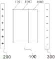
100、DGT采样器;1001、过滤膜;1002、扩散层;1003、吸附层; 1004、外壳;200、阳极;300、阴极;400、直流电源;500、框架;5001、电极连接件;5002、固定套管;100, DGT sampler; 1001, filter membrane; 1002, diffusion layer; 1003, adsorption layer; 1004, shell; 200, anode; 300, cathode; 400, DC power supply; 500, frame; 5001, electrode connector; 5002, fixed sleeve;
1、承载座;2、连接箱;3、连接板;4、三脚架支腿;5、定位插杆;6、定深浮球;7、定位浮标;8、采样器安装部;9、第一连接绳;10、第二连接绳;11、连接件;12、第一螺柱;13、导向杆;14、第一驱动装置;15、第二驱动装置;16、螺纹杆;17、空腔;18、移动件;19、转动件;20、定位齿;21、第三驱动装置;22、钻头;23、第二螺柱; 24、配重件;25、锁紧螺母;26、加长杆;27、收卷辊;28、限位盘; 29、转轴;30、第一摇柄;31、活动件;32、压紧盘;33、双向螺杆; 34、第二摇柄;35、导向槽;36、导向块;37、开口;38、抓地板。1. Bearing seat; 2. Connecting box; 3. Connecting plate; 4. Tripod legs; 5. Positioning rod; 6. Fixed depth float; 7. Positioning buoy; 8. Sampler installation part; 9. First connecting rope; 10, second connecting rope; 11, connecting piece; 12, first stud; 13, guide rod; 14, first driving device; 15, second driving device; 16, threaded rod; 17, cavity ; 18, moving parts; 19, rotating parts; 20, positioning teeth; 21, third drive device; 22, drill bit; 23, second stud; 24, counterweight; 25, lock nut; 26, extension rod ; 27, rewinding roller; 28, limit plate; 29, shaft; 30, first crank; 31, movable part; 32, pressing plate; 33, two-way screw; 34, second crank; 35, guide Slot; 36, guide block; 37, opening; 38, grab the floor.
具体实施方式Detailed ways
下面结合附图来具体描述本发明的优选实施例,其中,附图构成本申请一部分,并与本发明的实施例一起用于阐释本发明的原理,并非用于限定本发明的范围。The preferred embodiments of the present invention are specifically described below with reference to the accompanying drawings, wherein the accompanying drawings constitute a part of the present application, and together with the embodiments of the present invention, are used to explain the principles of the present invention, but are not used to limit the scope of the present invention.
在本发明实施例的描述中,需要说明的是,除非另有明确的规定和限定,术语“相连”应做广义理解,例如,可以是固定连接,也可以是可拆卸连接,或一体地连接可以是机械连接,也可以是电连接可以是直接相连,也可以通过中间媒介间接相连。对于本领域的普通技术人员而言,可以根据具体情况理解上述术语在本发明中的具体含义。In the description of the embodiments of the present invention, it should be noted that, unless otherwise expressly specified and limited, the term "connected" should be understood in a broad sense, for example, it may be a fixed connection, a detachable connection, or an integral connection It can be a mechanical connection or an electrical connection. It can be directly connected or indirectly connected through an intermediate medium. For those of ordinary skill in the art, the specific meanings of the above terms in the present invention can be understood according to specific situations.
全文中描述使用的术语“顶部”、“底部”、“在……上方”、“下”和“在……上”是相对于装置的部件的相对位置,例如装置内部的顶部和底部衬底的相对位置。可以理解的是装置是多功能的,与它们在空间中的方位无关。The terms "top," "bottom," "above," "under," and "over" as used throughout the description are relative positions with respect to components of a device, such as top and bottom substrates inside the device relative position. It is understood that the devices are multifunctional regardless of their orientation in space.
实施例1Example 1
本发明的一个具体实施例,公开了一种水中离子快速采集方法,采集时,在DGT采样器100外设置平行电场,使得DGT采样器100在设置平行电场的吸附环境进行离子吸附。A specific embodiment of the present invention discloses a rapid collection method of ions in water. During collection, a parallel electric field is set outside the
与现有技术相比,本实施例提供的水中离子快速采集方法,通过在 DGT采样器的吸附环境中加设平行电场中,以增加了水体中金属离子的迁移率,在相同时间内可以吸附更多的离子,加快实验进程。不同于传统DGT的被动采样方式,本申请通过在DGT采样器外设置平行电场,可以增加金属离子迁移率,还能够模拟生物的某些主动吸附方式,具有广泛的应用前景。Compared with the prior art, the method for rapid collection of ions in water provided by this embodiment increases the mobility of metal ions in the water by adding a parallel electric field to the adsorption environment of the DGT sampler, and can absorb the ions within the same time. More ions to speed up the experimental process. Different from the passive sampling method of traditional DGT, the present application can increase the mobility of metal ions by setting a parallel electric field outside the DGT sampler, and can also simulate some active adsorption methods of organisms, which has broad application prospects.
Fick第一扩散定律如公式(1)所示:Fick's first law of diffusion is shown in formula (1):

其中,J为待测元素扩散通量,D为待测元素扩散系数;c是待测元素浓度;l是扩散距离,dc/dl就是浓度扩散梯度。Among them, J is the diffusion flux of the element to be measured, D is the diffusion coefficient of the element to be measured; c is the concentration of the element to be measured; l is the diffusion distance, and dc/dl is the concentration diffusion gradient.
DGT原理如图1所示,金属离子通过扩散层1002扩散进入吸附层 1003,被吸附层1003吸附,吸附层吸附量与扩散速率,扩散层面积与厚度相关。基于公式(1)得到下述公式(1′):The principle of DGT is shown in Figure 1. Metal ions diffuse into the

其中,D是扩散常数,g是扩散层厚度,Cb溶液中待测物质含量, C′则是吸附层表面待测物质的含量。Among them, D is the diffusion constant, g is the thickness of the diffusion layer, the content of the substance to be tested in theCb solution, and C' is the content of the substance to be tested on the surface of the adsorption layer.
吸附层吸附的量MDGT的计算公式(2)为:The calculation formula (2) of the amount MDGT adsorbed by the adsorption layer is:
MDGT=t×A×J (2)MDGT = t × A × J (2)
其中,t为实验时间,A为扩散层窗口面积;Among them, t is the experimental time, A is the window area of the diffusion layer;
公式(1′)和(2)合并后可得到吸附层吸附的量MDGT的计算公式(3) 为:After combining formulas (1′) and (2), the calculation formula (3) of the amount MDGT adsorbed by the adsorption layer can be obtained as:

根据公式(3)计算溶液中的待测物质浓度,如果C'为0,则说明该元素为完全活性,其被吸附层全部吸收,因此得到溶液中待测物质含量Cb,计算公式为:
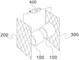
在外加平行电场的情况下,如图2所示,平行电场内设置1个DGT 采样器,则阳离子沿着电场方向从电场正极向负极迁移,叠加上浓度扩散梯度使得在吸附层吸附的阳离子的量比无电场情况下增加;而阴离子则会相对减少;中性分子不受电场影响,吸附的量与无电场情况下相同。In the case of an external parallel electric field, as shown in Fig. 2, a DGT sampler is set in the parallel electric field, and the cations migrate from the positive electrode to the negative electrode along the electric field direction, and the concentration diffusion gradient is superimposed to make the cations adsorbed in the adsorption layer. Compared with the case of no electric field, the amount of anions will be relatively reduced; neutral molecules are not affected by the electric field, and the amount of adsorption is the same as that in the case of no electric field.
如图3至图6所示,平行电场内设置2个DGT采样器,两个DGT 采样器相对分别置于电场正负两极,则正极附近的DGT吸附层中,阴离子吸附量增加,阳离子吸附量下降;负极附近DGT吸附层中,阳离子吸附量增加,阴离子吸附量下降;对于中性分子,正负两极附近的DGT吸附层吸附量均不变。通过设置两个DGT采样器,可以区分阴阳离子,且通过不同化学形态的元素在电场中的迁移率差异,可以对其进行区分,是一种高效的化学形态分析手段。As shown in Figure 3 to Figure 6, two DGT samplers are installed in the parallel electric field, and the two DGT samplers are placed at the positive and negative poles of the electric field respectively. In the DGT adsorption layer near the negative electrode, the adsorption amount of cations increased, and the adsorption amount of anions decreased; for neutral molecules, the adsorption amount of the DGT adsorption layer near the positive and negative poles remained unchanged. By setting two DGT samplers, anions and cations can be distinguished, and elements of different chemical forms can be distinguished by their mobility differences in the electric field, which is an efficient chemical form analysis method.
本实施例中,由于DGT采样器100位于平行电场中,当对DGT采样器施加平行电场之后,带电粒子在电场驱动下运动,待测元素扩散通量计算公式(4)为:In the present embodiment, since the

公式(4)前半部分和Fick第一扩散定律一样,后半部分则是元素在电场作用下的运动,其中u是离子在电场作用下的迁移率(泳动度),Cb是溶液中离子总浓度,E是电场强度,
因此,公式(4)可以改写为(4′):Therefore, formula (4) can be rewritten as (4′):

当稳定的扩散梯度形成之后,待测元素扩散通量计算公式表示为公式(5):When a stable diffusion gradient is formed, the calculation formula of the diffusion flux of the element to be measured is expressed as formula (5):

其中,g是扩散层厚度Cb溶液中待测物质含量,c′是待测元素在 DGT吸附层表面的浓度,△U为扩散层之间的电势差。Among them, g is the content of the substance to be tested in the diffusion layer thickness Cb solution, c' is the concentration of the tested element on the surface of the DGT adsorption layer, and ΔU is the potential difference between the diffusion layers.
进一步地,如果c′忽略不计,即待测元素被吸附层完全吸收,则待测元素扩散通量计算公式为公式(6):Further, if c′ is neglected, that is, the element to be tested is completely absorbed by the adsorption layer, the calculation formula of the diffusion flux of the element to be tested is formula (6):

由上述公式推算出金属元素在DGT采样器100吸附层1003上待测金属元素吸附量的计算公式(7):The calculation formula (7) of the adsorption amount of the metal element to be measured on the

其中,ΔU与施加在电极上的电压U相关,即如下式公式(8)所示:Among them, ΔU is related to the voltage U applied to the electrode, which is shown in the following formula (8):
ΔU=σ×U (8)ΔU=σ×U (8)
其中,σ为电极参数(常数),与电极的形状、电极之间的距离、扩散膜的性质、介质的介电常数以及其他影响因子相关。Among them, σ is the electrode parameter (constant), which is related to the shape of the electrode, the distance between the electrodes, the properties of the diffusion film, the dielectric constant of the medium and other influencing factors.
在一个确定的系统内,特定离子的u和σ的值都是确定的常数,如果将它们的乘积定义为电场扩散梯度(E-DGT)系数κ=u×σ,则公式(7) 可以改写为公式(9):In a definite system, the values of u and σ for a specific ion are both definite constants. If their product is defined as the electric field diffusion gradient (E-DGT) coefficient κ = u × σ, then formula (7) can be rewritten as is formula (9):

其中,κ是可测量的量,MDGT与U理论上呈成线性关系,如果MDGT对 U作图,其斜率s为
如图7所示,获得E-DGT吸附层的元素吸附量与电压的关系,在一定电压范围内,E-DGT的吸附量随电压增加而增加,吸附量与电压的关系近似为一条直线,在吸附量-电压图上,该直线的斜率s为

基于待测金属元素吸附量MDGT,当κ已知的情况下,由下述公式(10) 计算获得未知溶液的浓度Cb:Based on the adsorption amount of the metal element to be measured MDGT , when κ is known, the concentration Cb of the unknown solution can be calculated from the following formula (10):

本申请中所使用的符号/英文缩写如下表所示:The symbols/abbreviations used in this application are shown in the following table:


实施例2Example 2
本发明的又一具体实施例,公开了一种水中离子快速采集系统,应用于实施例1中的水中离子快速采集方法,如图2至图6所示,水中离子快速采集系统包括:Another specific embodiment of the present invention discloses a rapid collection system of ions in water, which is applied to the rapid collection method of ions in water in
平行电场发生组件,被配置为产生稳定的平行电场;a parallel electric field generating component configured to generate a stable parallel electric field;
DGT采样器100,DGT采样器100置于平行电场内,以吸附水体中的离子;
框架500,框架500具有安装空间,以备安装DGT采样器100和平行电场发生组件;a
固定机构,固定机构与框架500拆卸连接,固定机构能够将DGT采样器100和平行电场发生组件限定在指定水深位置。A fixing mechanism, the fixing mechanism is detachably connected with the
实施时,利用固定机构将DGT采样器100和平行电场发生组件置于水体中,并将其限定在指定水深位置,利用平行电场发生组件在DGT采样器100所在区域产生平行电场,DGT采样器100的吸附层1003吸附水中金属元素,经过一定吸附时间后,完成样品采集,将DGT采样器100 和平行电场发生组件从水体中移出,进行后续试验操作。During implementation, the
与现有技术相比,本实施例提供的水中离子快速采集系统,通过在传统DGT采样器外增设平行电场,使得DGT采样器置于一个稳定的平行电场环境中,增加了水体中金属离子的迁移率,在相同时间内可以吸附更多的离子,加快实验进程。而且,通过设置固定机构使DGT采样器 100和平行电场发生组件能够稳定的限定在指定水深位置,进而实现指定水深的采样。Compared with the prior art, the water ion rapid collection system provided by this embodiment, by adding a parallel electric field outside the traditional DGT sampler, enables the DGT sampler to be placed in a stable parallel electric field environment, which increases the concentration of metal ions in the water body. Mobility, more ions can be adsorbed in the same time, speeding up the experimental process. Moreover, by setting the fixing mechanism, the
本实施例中,平行电场发生组件包括阳极200、阴极300及直流电源400,阳极200与阴极300平行设置,并分别与直流电源400的正极和负极连接。In this embodiment, the parallel electric field generating component includes an
进一步地,平行电场的电场线与DGT采样器100的轴线平行,以提升离子的吸附效率及吸附量。Further, the electric field lines of the parallel electric field are parallel to the axis of the
本实施例中,DGT采样器100包括外壳1004,外壳1004内同轴依次设置有过滤膜1001、扩散层1002和吸附层1003。In this embodiment, the
本实施例中,平行电场内可以设置1个或多个DGT采样器。In this embodiment, one or more DGT samplers may be arranged in the parallel electric field.
如图2所示,平行电场内设置1个DGT采样器,则阳离子沿着电场方向从电场正极向负极迁移,叠加上浓度扩散梯度使得在吸附层吸附的阳离子的量比无电场情况下增加;而阴离子则会相对减少;中性分子不受电场影响,吸附的量与无电场情况下相同。As shown in Fig. 2, when a DGT sampler is installed in the parallel electric field, the cations migrate from the positive electrode to the negative electrode along the electric field direction, and the concentration diffusion gradient is superimposed, so that the amount of cations adsorbed by the adsorption layer is increased compared with the case of no electric field; The anions are relatively reduced; neutral molecules are not affected by the electric field, and the amount of adsorption is the same as that in the absence of the electric field.
如图3至图6所示,平行电场内设置2个DGT采样器,两个DGT 采样器相对分别置于电场正负两极,则正极附近的DGT吸附层中,阴离子吸附量增加,阳离子吸附量下降;负极附近DGT吸附层中,阳离子吸附量增加,阴离子吸附量下降;对于中性分子,正负两极附近的DGT吸附层吸附量均不变。通过设置两个DGT采样器,可以区分阴阳离子,且通过不同化学形态的元素在电场中的迁移率差异,可以对其进行区分,是一种高效的化学形态分析手段。As shown in Figure 3 to Figure 6, two DGT samplers are installed in the parallel electric field, and the two DGT samplers are placed at the positive and negative poles of the electric field respectively. In the DGT adsorption layer near the negative electrode, the adsorption amount of cations increased, and the adsorption amount of anions decreased; for neutral molecules, the adsorption amount of the DGT adsorption layer near the positive and negative poles remained unchanged. By setting two DGT samplers, anions and cations can be distinguished, and elements of different chemical forms can be distinguished by their mobility differences in the electric field, which is an efficient chemical form analysis method.
具体而言,DGT采样器100的数量为两个,第一DGT采样器与第二 DGT采样器同轴设置。两个采样器100优选采用如下两种布置方式:Specifically, the number of
第一种布置方式,第一DGT采样器的过滤膜1001与第二DGT采样器的过滤膜1001相对设置,第一DGT采样器的吸附层1003朝向阳极 200,第二DGT采样器的吸附层1003朝向阴极300。第一DGT采样器吸附水体中的阴离子,第二DGT采样器吸附水体中的金属阳离子。In the first arrangement, the
第二种布置方式,第一DGT采样器的吸附层1003与第二DGT采样器的吸附层1003相对设置,第一DGT采样器的过滤膜1001朝向阳极 200,第二DGT采样器的过滤膜1001朝向阴极300。第一DGT采样器吸附水体中的金属阳离子,第二DGT采样器吸附水体中的阴离子。In the second arrangement, the
本实施例的一个可选实施方式,框架500的安装空间与水体连通,安装空间内安装DGT采样器100和平行电场发生组件。通过设置框架500 以提升DGT采样器100和平行电场发生组件的安装稳定性,使得DGT 采样器100的轴线与平行电场的电场线始终平行,从而保证二者具有相对稳定的位置关系,确保吸附效率。In an optional implementation of this embodiment, the installation space of the
进一步地,固定机构与框架500通过采样器安装部8可拆卸连接,采样器安装部8可以为绳索,方便拆卸安装。Further, the fixing mechanism and the
进一步地,DGT采样器100通过固定套管5002与框架500连接,固定套管5002的轴线平行于平行电场的电场线布置;平行电场发生组件通过电极连接件5001与框架500连接。Further, the
为了便于更换拆卸DGT采样器100,第一DGT采样器和第二DGT 采样器螺纹连接于固定套管5002的两端。第一DGT采样器和第二DGT 采样器的结构相同,DGT采样器的外壳1004设有外螺纹,固定套管5002 设有内螺纹,外壳1004的外螺纹与固定套管5002的外螺纹相适配。采用螺纹连接方式,便于拆装,提升试验效率。In order to facilitate replacement and disassembly of the
本实施例的一个可选实施方式,阳极200与阴极300均采用网状铂电极板,网状铂电极板的面积大于DGT采样器100的轴向面积,网状铂电极板的稳定性好,电场的稳定性更优。In an optional implementation of this embodiment, both the
本实施例中,固定机构主要起到固定DGT采样器100和平行电场发生组件的作用。如图8所示,固定机构包括承载座1、连接箱2、定深浮球6和定位浮标7;承载座1的下方设有定位插杆5,定位插杆5通过移动机构与承载座1连接,移动机构用于驱动定位插杆5在竖直方向上远离或靠近承载座1;承载座1的上部设有连接箱2,连接箱2内设有绕线组件,绕线组件包括设置于连接箱2内的转轴29、双向螺杆33、收卷辊 27、限位盘,转轴29连接有第一摇柄30,双向螺杆33连接有第二摇柄 34;绕线组件上缠绕有第一连接绳9,第一连接绳9的一端与定深浮球6 连接;框架500拆卸连接在第一连接绳9上;定深浮球6通过第二连接绳10与定位浮标7连接。In this embodiment, the fixing mechanism mainly plays the role of fixing the
具体而言,如图11所示,连接箱2设置在承载座1的顶部,连接箱 2内横向设置转轴29,且转轴29上设有第一摇柄30;收卷辊27设置在转轴29的中部,且收卷辊27的两侧设有限位盘28;双向螺杆33横向设置于连接箱2内并与其转动连接,且双向螺杆33上设有第二摇柄34;活动件31滑动设置于连接箱2内并位于收卷辊27的两侧,活动件31与双向螺杆33螺纹连接;活动件31上设有压紧盘32,压紧盘32抵住限位盘28,且压紧盘32和活动件31上分别设有供转轴29穿过的通孔;定深浮球6位于连接箱2的上方,第一连接绳9连接收卷辊27和定深浮球6;定位浮标7漂浮在水面上,第二连接绳10连接定深浮球6和定位浮标7。Specifically, as shown in FIG. 11 , the connection box 2 is arranged on the top of the bearing base 1 , a rotating shaft 29 is laterally arranged in the connecting box 2 , and the first crank handle 30 is arranged on the rotating shaft 29 ; the winding roller 27 is arranged on the rotating shaft 29 The middle part of the winding roller 27 is provided with limit disks 28 on both sides; the two-way screw 33 is laterally arranged in the connecting box 2 and connected to it in rotation, and the two-way screw 33 is provided with a second crank 34; the movable part 31 is slidably arranged Inside the connection box 2 and located on both sides of the winding roller 27, the movable member 31 is threadedly connected with the bidirectional screw rod 33; the movable member 31 is provided with a pressing plate 32, and the pressing plate 32 abuts against the limiting plate 28 and is pressed tightly The disk 32 and the movable part 31 are respectively provided with through holes for the rotating shaft 29 to pass through; the fixed-depth float 6 is located above the connection box 2, and the first connecting rope 9 connects the winding roller 27 and the fixed-depth float 6; the positioning buoy 7 floats on the water surface, and the second connecting rope 10 connects the depth-fixing float 6 and the positioning buoy 7 .
在一个可选的实施例中,移动机构包括第一螺柱12、导向杆13和第一驱动装置14,第一螺柱12的第一端和导向杆13的第一端均连接于承载座1的底部,第一螺柱12的第二端和导向杆13的第二端通过连接件 11与定位插杆5连接,具体的,定位插杆5的两侧对称设有两组连接件 11,第一组连接件与第一螺柱12螺纹连接,第二组连接件与导向杆13 滑动连接;第一驱动装置14设于承载座1上,第一驱动装置14的输出端与第一螺柱12连接。此结构的移动机构,结构简单,第一螺柱12与导向杆13平行设置,提高了定位插杆5的竖直移动稳定性,而且通过第一驱动装置14驱动定位插杆5向下移动,能够方便迅速插入河床基质,减少操作强度。In an optional embodiment, the moving mechanism includes a first stud 12 , a
本实施例中,承载座1上设有连接板3,连接板3的底部倾斜设置三脚架支腿4。在一个可选的实施例中,三脚架支腿4的数量为3个,均匀布置在连接板3的底部,且三脚架支腿4为伸缩结构,长度可调节,通过设置长度调节锁紧件实现三脚架支腿4的长度调节;三脚架支腿4与连接板3所呈角度可调节,三脚架支腿4与连接板3转动连接,连接板3 设有角度锁紧件,通过角度锁紧件调整三脚架支腿4与连接板3的角度。通过调整三脚架支腿4的长度、三脚架支腿4与连接板3角度,以适应不同地形的河床基质,提高装置的稳定性和应用广泛性。In this embodiment, the
在一个可选的实施例中,第二连接绳10的两端分别设有挂钩,定深浮球6和定位浮标7上分别设有固定环,且两挂钩分别勾住对应的固定环,方便对第二连接绳10进行更换,有助于使用。In an optional embodiment, hooks are respectively provided at both ends of the second connecting
在一个可选的实施例中,固定机构还包括配重组件,配重组件的数量为多组,多组配种组件均匀布设在连接板3上,每组配重组件的重量可调节。如图12至图13所示,配重组件包括第二螺柱23、配重件24和锁紧螺母25;第二螺柱23竖直设置在连接板3上,配重件24的中部设有通孔,且配重件24套在第二螺柱23上;锁紧螺母25与第二螺柱23 螺纹连接,锁紧螺母25压住位于最上方的配重件24,且锁紧螺母25的外周面设有多组加长杆26。工作中,根据需要将一定数量的配重件24套在第二螺柱23上,然后将锁紧螺母25与第二螺柱23螺纹连接,并对加长杆26施加力的作用以使锁紧螺母25进行转动,锁紧螺母25进行转动的同时还向下运动,直至锁紧螺母25压住位于最上方的配重件24,实现对所有配重件24的固定,配重件24的设置能够增加装置的重量以提高装置在水中的稳定性。In an optional embodiment, the fixing mechanism further includes a counterweight assembly, the number of which is multiple groups, the multiple groups of seeding assemblies are evenly arranged on the connecting
在一个可选的实施例中,活动件31的底部设有导向块36,连接箱2 的内部底端横向设置导向槽35,导向块36位于导向槽35内并与连接箱 2滑动连接。In an optional embodiment, the bottom of the
在一个可选的实施例中,第一连接绳9上设有刻度值,能够直接了解第一连接绳9的释放长度,方便调节;压紧盘32上设有防滑层,有助于提高对收卷辊27的固定效果;导向杆13的底部设有限位块,限位块对定位插杆5起到限位作用,有效防止其与导向杆13脱离。In an optional embodiment, the first connecting
在一个可选的实施例中,定位插杆5的底端转动设置钻头22,定位插杆5内设有第三驱动装置21,且第三驱动装置21的输出端与钻头22 连接,安装时,第一驱动装置14驱动定位插杆5下降,直至定位插杆5 前端的钻头22与河床基质接触,第三驱动装置21动作驱动钻头22钻进河床基质,从而提升定位插杆5的安装稳定性。In an optional embodiment, the bottom end of the
为了进一步提升定位插杆5在河床基质的安装稳定性,定位插杆5 为空心结构,具有竖直设置的空腔17,空腔17内安装有横插组件,定位插杆5的侧壁设置开口37,开口37与空腔17连通,横插组件能够在第二驱动装置15的驱动下伸出或缩回开口37。初始状态下,横插组件完全缩回至定位插杆5的空腔17内,当定位插杆5插入钻头22施工的钻孔内后,第二驱动装置15驱动横插组件伸出开口37,插入钻孔的侧壁,从而提升定位插杆5在河床基质的安装稳定性。In order to further improve the installation stability of the
具体而言,如图9至图10所示,横插组件包括螺纹杆16、移动件 18、定位齿20;定位插杆5内竖直设置空腔17,空腔17内竖直安装有螺纹杆16,螺纹杆16与定位插杆5转动连接;定位插杆5上设有第二驱动装置15,且第二驱动装置15的输出端与螺纹杆16连接,用于驱动螺纹杆16在空腔17内转动;螺纹杆16上螺纹安装有移动件18,移动件 18的外周面倾斜设置转动件19,转动件19与移动件18的外周面转动连接;定位插杆5的侧壁设置开口37,开口37与空腔17连通,也即定位插杆5上水平设置开口37,开口37内安装有定位齿20,且定位齿20通过转动件19与移动件18连接,转动件19的两端分别与定位齿20、移动件18转动连接。当第二驱动装置15驱动螺纹杆16转动时,移动件18 沿螺纹杆16的轴向移动,移动件18与螺纹杆16的倾斜角度发生变化,使得定位齿20伸出或缩回开口37。Specifically, as shown in FIG. 9 to FIG. 10 , the horizontal insertion assembly includes a threaded
在一个可选的实施例中,移动件18的数目为多组,并沿竖直方向等距设置,定位齿20沿竖直方向等距设有多圈,且每圈定位齿20围绕移动件18呈环形阵列分布,多组移动件18使得装置的稳定性更好,而且对称设置便于定位齿20伸出或缩回开口37,提高装置的工作可靠性。In an optional embodiment, the number of the moving
考虑到河床基质类型多样,河床基质包括污泥、细砂质、沙泥混合质、鹅卵石等多种类型,不同类型河床基质的硬度差异影响三脚架支腿4 的安装稳定性。基于上述原因,在一个可选的实施例中,如图8所示,三脚架支腿4上设有抓地板38,抓地板38固定设于三脚架支腿4的端部,抓地板38水平设置,三脚架支腿4通过抓地板38与河床基质直接面接触,增大了三脚架支腿4与河床基质的接触面积,从而增加了采集系统的稳定性,此结构适用于平面河床基质的水体采样。Considering the various types of river bed substrates, including sludge, fine sand, sand-mud mixture, cobblestone, etc., the difference in hardness of different types of river bed substrates affects the installation stability of
固定机构的操作步骤如下:The operation steps of the fixing mechanism are as follows:
S1、摇动第一摇柄30以使转轴29进行转动,收卷辊27随之进行转动并不断释放第一连接绳9,当释放到一定长度后停止放绳操作;S1, shake the first crank handle 30 to make the
S2、放绳操作停止后,摇动第二摇柄34以使双向螺杆33进行转动,两活动件31进行相向运动,两压紧盘32之间的距离不断减小并最终抵住限位盘,以对收卷辊27进行固定;S2. After the rope-releasing operation is stopped, shake the second crank handle 34 to make the
S3、将整个采集系统投放入水中定深浮球6悬浮于水中,定位浮标7 漂浮在水面上,调整三脚架支腿4的长度和各三脚架支腿24上的配重件 24数量,使三脚架支腿4的端部与河床基体稳定接触,保证采集系统的中心位于其重心线上,实现对采集系统的固定;S3. Put the entire collection system into the water and the depth-fixing
S4、第一驱动装置14驱动第一螺柱12转动,第三驱动装置21驱动钻头22进行水平方向圆周转动,定位插杆5在导向杆13的导向作用下不断下降,即定位插杆5不断向下插入淤泥中;S4. The
S5、当定位插杆5下降到一定深度后,使第一驱动装置14和第三驱动装置21停止运作;第二驱动装置15驱动螺纹杆16进行转动,各移动件18向下运动,转动件19的倾斜角度发生改变并使定位齿20穿出开口 37,各方向的定位齿水平插入淤泥中,在此过程中可以同时调整三脚架支腿4的脚端在河床基质上的凹凸位置,并通过增加配重件24,实现对装置的有效固定。S5. When the
与现有技术相比,本实施例提供的水中离子快速采集系统至少可实现如下有益效果之一:Compared with the prior art, the rapid collection system for ions in water provided by this embodiment can achieve at least one of the following beneficial effects:
1、通过设置三脚架支腿提升采集系统的稳定性,并且三脚架支腿长度可调节,通过设置长度调节锁紧件实现三脚架支腿的长度调节,三脚架支腿与连接板所呈角度可调节,通过调整三脚架支腿的长度、三脚架支腿与连接板角度,以适应不同地形的河床基质,提高装置的稳定性和应用广泛性。1. The stability of the acquisition system is improved by setting the tripod legs, and the length of the tripod legs can be adjusted. The length of the tripod legs can be adjusted by setting the length adjustment locking parts. The angle between the tripod legs and the connecting plate can be adjusted. Adjust the length of the tripod legs, the angle of the tripod legs and the connecting plate to adapt to the riverbed substrate of different terrains, and improve the stability and wide application of the device.
2、三脚架支腿通过抓地板固定于河床基质,利用抓地板增大三脚架支腿与河床基质的接触面积,从而提升采集系统的稳定性。2. The legs of the tripod are fixed to the riverbed substrate by the gripping floor, and the contact area between the tripod legs and the riverbed substrate is increased by the gripping floor, thereby improving the stability of the acquisition system.
3、通过设置多组配重组件,每组配重组件的重量可调节,以提升装置的稳定性。3. By setting up multiple sets of counterweight components, the weight of each set of counterweight components can be adjusted to improve the stability of the device.
4、通过在定位插杆的底端设置钻头,利用第三驱动装置驱动钻头钻进河床基质,从而提升定位插杆的安装稳定性。4. By arranging a drill bit at the bottom end of the positioning plunger, the third driving device is used to drive the drill bit to drill into the river bed matrix, thereby improving the installation stability of the positioning plunger.
以上所述,仅为本发明较佳的具体实施方式,但本发明的保护范围并不局限于此,任何熟悉本技术领域的技术人员在本发明揭露的技术范围内,可轻易想到的变化或替换,都应涵盖在本发明的保护范围之内。The above description is only a preferred embodiment of the present invention, but the protection scope of the present invention is not limited to this. Substitutions should be covered within the protection scope of the present invention.
Claims (10)
Translated fromChinese


Priority Applications (1)
| Application Number | Priority Date | Filing Date | Title |
|---|---|---|---|
| CN202110934951.6ACN113607605B (en) | 2021-08-16 | 2021-08-16 | A rapid collection system and method for ions in water |
Applications Claiming Priority (1)
| Application Number | Priority Date | Filing Date | Title |
|---|---|---|---|
| CN202110934951.6ACN113607605B (en) | 2021-08-16 | 2021-08-16 | A rapid collection system and method for ions in water |
Publications (2)
| Publication Number | Publication Date |
|---|---|
| CN113607605Atrue CN113607605A (en) | 2021-11-05 |
| CN113607605B CN113607605B (en) | 2024-02-09 |
Family
ID=78308605
Family Applications (1)
| Application Number | Title | Priority Date | Filing Date |
|---|---|---|---|
| CN202110934951.6AActiveCN113607605B (en) | 2021-08-16 | 2021-08-16 | A rapid collection system and method for ions in water |
Country Status (1)
| Country | Link |
|---|---|
| CN (1) | CN113607605B (en) |
Cited By (2)
| Publication number | Priority date | Publication date | Assignee | Title |
|---|---|---|---|---|
| CN114739870A (en)* | 2022-04-27 | 2022-07-12 | 长安大学 | Method for dividing sediment-water interface in water ecosystem |
| US12270736B1 (en)* | 2024-06-27 | 2025-04-08 | Inner Mongolia University of Science and Technology | DGT passive sampling device and method for water body detection |
Citations (15)
| Publication number | Priority date | Publication date | Assignee | Title |
|---|---|---|---|---|
| US3686089A (en)* | 1967-07-25 | 1972-08-22 | Emmanuel Korngold | Method of separation of ions from a solution |
| CN201454977U (en)* | 2009-04-28 | 2010-05-12 | 上海海事大学 | Electrokinetic Adsorption Composite Remediation Device for Heavy Metal Contaminated Soil |
| US20110162964A1 (en)* | 2007-11-30 | 2011-07-07 | Evgeniya Freydina | Systems and methods for water treatment |
| WO2012039312A1 (en)* | 2010-09-22 | 2012-03-29 | 日理工業株式会社 | Device for removing impurity ions |
| CN104823045A (en)* | 2012-11-29 | 2015-08-05 | 布鲁克·道尔顿公司 | Apparatus and method for cross-flow ion mobility spectrometry |
| US20170044032A1 (en)* | 2015-08-13 | 2017-02-16 | Korea Institute Of Geoscience And Mineral Resources (Kigam) | System for recovering multiple kinds of ions |
| CN108325508A (en)* | 2018-03-09 | 2018-07-27 | 北京交通大学 | Heavy metal available state adsorbed film and heavy metal available state detection method |
| CN109813635A (en)* | 2019-01-01 | 2019-05-28 | 中国人民解放军63653部队 | Based on electric field through the device of diffusion method measurement nucleic diffusion coefficient in rock soil medium |
| CN110702802A (en)* | 2019-10-24 | 2020-01-17 | 上海海洋大学 | A method for passive monitoring of antibiotic content in aquaculture water in situ |
| CN110849776A (en)* | 2019-11-26 | 2020-02-28 | 中国科学院城市环境研究所 | Method for measuring content of effective silicon in water body and soil |
| CN111044413A (en)* | 2020-01-07 | 2020-04-21 | 中国环境科学研究院 | Lake water body DGT test device and test method |
| CN212658570U (en)* | 2020-01-07 | 2021-03-05 | 中国环境科学研究院 | Lake Columnar Sediment DGT Probe Testing Device |
| US20210163319A1 (en)* | 2019-12-03 | 2021-06-03 | Iucf-Hyu (Industry-University Cooperation Foundation Hanyang University) | Water treatment apparatus and water treatment method using same |
| KR20210069590A (en)* | 2019-12-03 | 2021-06-11 | 한양대학교 산학협력단 | Water treatment apparatus and water treatment method using same |
| CN215931369U (en)* | 2021-08-16 | 2022-03-01 | 国家地质实验测试中心 | Quick collection system of aquatic ion |
- 2021
- 2021-08-16CNCN202110934951.6Apatent/CN113607605B/enactiveActive
Patent Citations (15)
| Publication number | Priority date | Publication date | Assignee | Title |
|---|---|---|---|---|
| US3686089A (en)* | 1967-07-25 | 1972-08-22 | Emmanuel Korngold | Method of separation of ions from a solution |
| US20110162964A1 (en)* | 2007-11-30 | 2011-07-07 | Evgeniya Freydina | Systems and methods for water treatment |
| CN201454977U (en)* | 2009-04-28 | 2010-05-12 | 上海海事大学 | Electrokinetic Adsorption Composite Remediation Device for Heavy Metal Contaminated Soil |
| WO2012039312A1 (en)* | 2010-09-22 | 2012-03-29 | 日理工業株式会社 | Device for removing impurity ions |
| CN104823045A (en)* | 2012-11-29 | 2015-08-05 | 布鲁克·道尔顿公司 | Apparatus and method for cross-flow ion mobility spectrometry |
| US20170044032A1 (en)* | 2015-08-13 | 2017-02-16 | Korea Institute Of Geoscience And Mineral Resources (Kigam) | System for recovering multiple kinds of ions |
| CN108325508A (en)* | 2018-03-09 | 2018-07-27 | 北京交通大学 | Heavy metal available state adsorbed film and heavy metal available state detection method |
| CN109813635A (en)* | 2019-01-01 | 2019-05-28 | 中国人民解放军63653部队 | Based on electric field through the device of diffusion method measurement nucleic diffusion coefficient in rock soil medium |
| CN110702802A (en)* | 2019-10-24 | 2020-01-17 | 上海海洋大学 | A method for passive monitoring of antibiotic content in aquaculture water in situ |
| CN110849776A (en)* | 2019-11-26 | 2020-02-28 | 中国科学院城市环境研究所 | Method for measuring content of effective silicon in water body and soil |
| US20210163319A1 (en)* | 2019-12-03 | 2021-06-03 | Iucf-Hyu (Industry-University Cooperation Foundation Hanyang University) | Water treatment apparatus and water treatment method using same |
| KR20210069590A (en)* | 2019-12-03 | 2021-06-11 | 한양대학교 산학협력단 | Water treatment apparatus and water treatment method using same |
| CN111044413A (en)* | 2020-01-07 | 2020-04-21 | 中国环境科学研究院 | Lake water body DGT test device and test method |
| CN212658570U (en)* | 2020-01-07 | 2021-03-05 | 中国环境科学研究院 | Lake Columnar Sediment DGT Probe Testing Device |
| CN215931369U (en)* | 2021-08-16 | 2022-03-01 | 国家地质实验测试中心 | Quick collection system of aquatic ion |
Non-Patent Citations (2)
| Title |
|---|
| 许明姣;: "Ag/AgCl电极测量水泥浆体中氯离子扩散系数", 混凝土, no. 11* |
| 陈金庆;王保国;吕宏凌;: "基于吸附-扩散机理研究钒离子透膜传质过程(Ⅰ)――离子膜吸附-扩散模型", 当代化工, no. 08* |
Cited By (2)
| Publication number | Priority date | Publication date | Assignee | Title |
|---|---|---|---|---|
| CN114739870A (en)* | 2022-04-27 | 2022-07-12 | 长安大学 | Method for dividing sediment-water interface in water ecosystem |
| US12270736B1 (en)* | 2024-06-27 | 2025-04-08 | Inner Mongolia University of Science and Technology | DGT passive sampling device and method for water body detection |
Also Published As
| Publication number | Publication date |
|---|---|
| CN113607605B (en) | 2024-02-09 |
Similar Documents
| Publication | Publication Date | Title |
|---|---|---|
| CN113607605A (en) | System and method for rapidly collecting ions in water | |
| CN210142010U (en) | Groundwater sampling device for hydrogeology | |
| CN218121460U (en) | Soil remediation's detection sampling device | |
| CN210123367U (en) | A multifunctional sampling device for water bodies containing carbon nanotubes | |
| CN210572178U (en) | Portable environment detection equipment | |
| CN113607487B (en) | A water sample collection device and method | |
| CN113607486B (en) | A water sample collection device and method based on parallel electric field | |
| CN110687146B (en) | X-ray diffraction in-situ testing device for electrochromic film | |
| CN115180464A (en) | A depth measuring device for water conservancy project supervision and its measuring method | |
| CN206515284U (en) | Adjustable three-electrode electro Chemical fixing device for experiment | |
| CN206799776U (en) | Magnetohydrodynamics electrodeposition process prepares the regulation device of high-resolution αsource | |
| JP2021022550A (en) | Manufacturing equipment for silicon carbide negative electrode material for lithium-ion secondary battery | |
| CN212732244U (en) | Multifunctional physical experiment table assembly | |
| CN215525602U (en) | Sample replacing equipment for neutron scattering experiment | |
| CN222474380U (en) | Floating type water quality analyzer bracket | |
| CN215139799U (en) | A reaction device for electrode foil production and processing | |
| CN206244475U (en) | A kind of two-dimensional/three-dimensional electrode reactor device of adjusting plate spacing | |
| CN103834993A (en) | Preparation method of graphene dendritic crystals and graphene dendritic crystals thereof | |
| CN208766468U (en) | A kind of corrosion-resistant quartz cassette | |
| CN207648374U (en) | The adjustable firmware device of measurement detection support | |
| CN220120413U (en) | Positioning and fixing device of lead-zinc mining area heavy metal contaminated soil sampler | |
| CN222671480U (en) | A water quality sampling device | |
| CN218254281U (en) | A new energy vehicle lithium battery plate processing device | |
| CN217249692U (en) | Magnetic force frame for experiments | |
| CN219391442U (en) | Sampling equipment for water environment detection |
Legal Events
| Date | Code | Title | Description |
|---|---|---|---|
| PB01 | Publication | ||
| PB01 | Publication | ||
| SE01 | Entry into force of request for substantive examination | ||
| SE01 | Entry into force of request for substantive examination | ||
| GR01 | Patent grant | ||
| GR01 | Patent grant |