CN113582704B - Production line, method and sintered product - Google Patents
Production line, method and sintered productDownload PDFInfo
- Publication number
- CN113582704B CN113582704BCN202110824498.3ACN202110824498ACN113582704BCN 113582704 BCN113582704 BCN 113582704BCN 202110824498 ACN202110824498 ACN 202110824498ACN 113582704 BCN113582704 BCN 113582704B
- Authority
- CN
- China
- Prior art keywords
- sintered
- furnace
- tape
- belt
- ribbon
- Prior art date
- Legal status (The legal status is an assumption and is not a legal conclusion. Google has not performed a legal analysis and makes no representation as to the accuracy of the status listed.)
- Active
Links
- 238000004519manufacturing processMethods0.000titleabstractdescription62
- 238000000034methodMethods0.000titledescription46
- 239000000919ceramicSubstances0.000claimsdescription78
- 239000002223garnetSubstances0.000claimsdescription8
- 229910052744lithiumInorganic materials0.000claimsdescription5
- WHXSMMKQMYFTQS-UHFFFAOYSA-NLithiumChemical compound[Li]WHXSMMKQMYFTQS-UHFFFAOYSA-N0.000claimsdescription4
- 230000000994depressogenic effectEffects0.000claims1
- 238000005245sinteringMethods0.000abstractdescription89
- 239000011230binding agentSubstances0.000abstractdescription88
- 239000000463materialSubstances0.000abstractdescription63
- 230000007547defectEffects0.000abstractdescription44
- 229910010293ceramic materialInorganic materials0.000abstractdescription2
- MCMNRKCIXSYSNV-UHFFFAOYSA-NZirconium dioxideChemical compoundO=[Zr]=OMCMNRKCIXSYSNV-UHFFFAOYSA-N0.000description34
- 239000002245particleSubstances0.000description21
- PNEYBMLMFCGWSK-UHFFFAOYSA-Naluminium oxideInorganic materials[O-2].[O-2].[O-2].[Al+3].[Al+3]PNEYBMLMFCGWSK-UHFFFAOYSA-N0.000description17
- 238000010438heat treatmentMethods0.000description11
- 239000002002slurrySubstances0.000description11
- 238000000926separation methodMethods0.000description10
- 229910010272inorganic materialInorganic materials0.000description9
- 239000011147inorganic materialSubstances0.000description9
- 238000005498polishingMethods0.000description9
- 239000010408filmSubstances0.000description8
- 229910001233yttria-stabilized zirconiaInorganic materials0.000description8
- 239000000853adhesiveSubstances0.000description7
- 230000001070adhesive effectEffects0.000description7
- 238000007872degassingMethods0.000description7
- 239000010419fine particleSubstances0.000description7
- 238000000227grindingMethods0.000description7
- 238000003801millingMethods0.000description7
- 230000008901benefitEffects0.000description6
- 229910052500inorganic mineralInorganic materials0.000description6
- 239000011707mineralSubstances0.000description6
- 239000000843powderSubstances0.000description6
- 239000011819refractory materialSubstances0.000description6
- 239000000758substrateSubstances0.000description6
- 238000005299abrasionMethods0.000description5
- 229910052799carbonInorganic materials0.000description5
- 238000005266castingMethods0.000description5
- 239000011521glassSubstances0.000description5
- 238000005520cutting processMethods0.000description4
- 229910052751metalInorganic materials0.000description4
- 239000002184metalSubstances0.000description4
- 230000007704transitionEffects0.000description4
- 230000005540biological transmissionEffects0.000description3
- 238000010586diagramMethods0.000description3
- 239000011094fiberboardSubstances0.000description3
- 238000001914filtrationMethods0.000description3
- 238000003780insertionMethods0.000description3
- 230000037431insertionEffects0.000description3
- 239000011229interlayerSubstances0.000description3
- 239000000203mixtureSubstances0.000description3
- 230000003287optical effectEffects0.000description3
- 229920002037poly(vinyl butyral) polymerPolymers0.000description3
- 238000007493shaping processMethods0.000description3
- HBMJWWWQQXIZIP-UHFFFAOYSA-Nsilicon carbideChemical compound[Si+]#[C-]HBMJWWWQQXIZIP-UHFFFAOYSA-N0.000description3
- 229910010271silicon carbideInorganic materials0.000description3
- 229910052596spinelInorganic materials0.000description3
- 239000011029spinelSubstances0.000description3
- 229920002799BoPETPolymers0.000description2
- CPLXHLVBOLITMK-UHFFFAOYSA-NMagnesium oxideChemical compound[Mg]=OCPLXHLVBOLITMK-UHFFFAOYSA-N0.000description2
- 239000005041Mylar™Substances0.000description2
- VYPSYNLAJGMNEJ-UHFFFAOYSA-NSilicium dioxideChemical compoundO=[Si]=OVYPSYNLAJGMNEJ-UHFFFAOYSA-N0.000description2
- QCWXUUIWCKQGHC-UHFFFAOYSA-NZirconiumChemical compound[Zr]QCWXUUIWCKQGHC-UHFFFAOYSA-N0.000description2
- 238000005452bendingMethods0.000description2
- 239000003610charcoalSubstances0.000description2
- 239000000356contaminantSubstances0.000description2
- 238000007796conventional methodMethods0.000description2
- RKTYLMNFRDHKIL-UHFFFAOYSA-Ncopper;5,10,15,20-tetraphenylporphyrin-22,24-diideChemical compound[Cu+2].C1=CC(C(=C2C=CC([N-]2)=C(C=2C=CC=CC=2)C=2C=CC(N=2)=C(C=2C=CC=CC=2)C2=CC=C3[N-]2)C=2C=CC=CC=2)=NC1=C3C1=CC=CC=C1RKTYLMNFRDHKIL-UHFFFAOYSA-N0.000description2
- 229910052878cordieriteInorganic materials0.000description2
- DOIRQSBPFJWKBE-UHFFFAOYSA-Ndibutyl phthalateChemical compoundCCCCOC(=O)C1=CC=CC=C1C(=O)OCCCCDOIRQSBPFJWKBE-UHFFFAOYSA-N0.000description2
- JSKIRARMQDRGJZ-UHFFFAOYSA-Ndimagnesium dioxido-bis[(1-oxido-3-oxo-2,4,6,8,9-pentaoxa-1,3-disila-5,7-dialuminabicyclo[3.3.1]nonan-7-yl)oxy]silaneChemical compound[Mg++].[Mg++].[O-][Si]([O-])(O[Al]1O[Al]2O[Si](=O)O[Si]([O-])(O1)O2)O[Al]1O[Al]2O[Si](=O)O[Si]([O-])(O1)O2JSKIRARMQDRGJZ-UHFFFAOYSA-N0.000description2
- 238000001035dryingMethods0.000description2
- 238000005516engineering processMethods0.000description2
- 239000000835fiberSubstances0.000description2
- 239000007789gasSubstances0.000description2
- 239000002241glass-ceramicSubstances0.000description2
- 239000008187granular materialSubstances0.000description2
- 239000012535impuritySubstances0.000description2
- 230000000977initiatory effectEffects0.000description2
- 239000010954inorganic particleSubstances0.000description2
- 239000010410layerSubstances0.000description2
- 230000033001locomotionEffects0.000description2
- 238000012986modificationMethods0.000description2
- 230000004048modificationEffects0.000description2
- 239000000123paperSubstances0.000description2
- -1polyalkylcarbonatePolymers0.000description2
- 238000012545processingMethods0.000description2
- 238000010345tape castingMethods0.000description2
- 238000012546transferMethods0.000description2
- 238000002834transmittanceMethods0.000description2
- XLYOFNOQVPJJNP-UHFFFAOYSA-NwaterSubstancesOXLYOFNOQVPJJNP-UHFFFAOYSA-N0.000description2
- QYEXBYZXHDUPRC-UHFFFAOYSA-NB#[Ti]#BChemical compoundB#[Ti]#BQYEXBYZXHDUPRC-UHFFFAOYSA-N0.000description1
- 229910052580B4CInorganic materials0.000description1
- OKTJSMMVPCPJKN-UHFFFAOYSA-NCarbonChemical compound[C]OKTJSMMVPCPJKN-UHFFFAOYSA-N0.000description1
- 101710104662Enterotoxin type C-3Proteins0.000description1
- 102100030844Exocyst complex component 1Human genes0.000description1
- 229910015372FeAlInorganic materials0.000description1
- 229910000604FerrochromeInorganic materials0.000description1
- 240000001973Ficus microcarpaSpecies0.000description1
- 102100040837Galactoside alpha-(1,2)-fucosyltransferase 2Human genes0.000description1
- 101000893710Homo sapiens Galactoside alpha-(1,2)-fucosyltransferase 2Proteins0.000description1
- 229910000502Li-aluminosilicateInorganic materials0.000description1
- 229910020068MgAlInorganic materials0.000description1
- 229910016583MnAlInorganic materials0.000description1
- 239000004677NylonSubstances0.000description1
- 229910019142PO4Inorganic materials0.000description1
- 101150040428SEC4 geneProteins0.000description1
- 229910052581Si3N4Inorganic materials0.000description1
- 241000519995Stachys sylvaticaSpecies0.000description1
- 101000882406Staphylococcus aureus Enterotoxin type C-1Proteins0.000description1
- 101000882403Staphylococcus aureus Enterotoxin type C-2Proteins0.000description1
- 229910033181TiB2Inorganic materials0.000description1
- NIXOWILDQLNWCW-UHFFFAOYSA-Nacrylic acid groupChemical groupC(C=C)(=O)ONIXOWILDQLNWCW-UHFFFAOYSA-N0.000description1
- 239000000654additiveSubstances0.000description1
- CSDREXVUYHZDNP-UHFFFAOYSA-NalumanylidynesiliconChemical compound[Al].[Si]CSDREXVUYHZDNP-UHFFFAOYSA-N0.000description1
- 229910052782aluminiumInorganic materials0.000description1
- XAGFODPZIPBFFR-UHFFFAOYSA-NaluminiumChemical compound[Al]XAGFODPZIPBFFR-UHFFFAOYSA-N0.000description1
- 229910000323aluminium silicateInorganic materials0.000description1
- 239000002518antifoaming agentSubstances0.000description1
- 238000013459approachMethods0.000description1
- 238000000149argon plasma sinteringMethods0.000description1
- 238000000498ball millingMethods0.000description1
- INAHAJYZKVIDIZ-UHFFFAOYSA-Nboron carbideChemical compoundB12B3B4C32B41INAHAJYZKVIDIZ-UHFFFAOYSA-N0.000description1
- 239000002041carbon nanotubeSubstances0.000description1
- 229910021393carbon nanotubeInorganic materials0.000description1
- 238000000576coating methodMethods0.000description1
- 239000003086colorantSubstances0.000description1
- 238000013329compoundingMethods0.000description1
- 238000010276constructionMethods0.000description1
- 238000010924continuous productionMethods0.000description1
- 238000009770conventional sinteringMethods0.000description1
- 238000005336crackingMethods0.000description1
- 238000004132cross linkingMethods0.000description1
- 238000013461designMethods0.000description1
- KZHJGOXRZJKJNY-UHFFFAOYSA-Ndioxosilane;oxo(oxoalumanyloxy)alumaneChemical compoundO=[Si]=O.O=[Si]=O.O=[Al]O[Al]=O.O=[Al]O[Al]=O.O=[Al]O[Al]=OKZHJGOXRZJKJNY-UHFFFAOYSA-N0.000description1
- 239000002270dispersing agentSubstances0.000description1
- 230000008030eliminationEffects0.000description1
- 238000003379elimination reactionMethods0.000description1
- 238000002474experimental methodMethods0.000description1
- 239000010433feldsparSubstances0.000description1
- 238000010304firingMethods0.000description1
- 239000011888foilSubstances0.000description1
- 230000005484gravityEffects0.000description1
- 206010022000influenzaDiseases0.000description1
- 239000004615ingredientSubstances0.000description1
- 238000007689inspectionMethods0.000description1
- 238000009434installationMethods0.000description1
- 238000009413insulationMethods0.000description1
- 239000000395magnesium oxideSubstances0.000description1
- 239000012528membraneSubstances0.000description1
- 239000002923metal particleSubstances0.000description1
- 150000002739metalsChemical class0.000description1
- 238000002156mixingMethods0.000description1
- 229910052863mulliteInorganic materials0.000description1
- 229920001778nylonPolymers0.000description1
- 239000003921oilSubstances0.000description1
- 238000013021overheatingMethods0.000description1
- 230000003647oxidationEffects0.000description1
- 238000007254oxidation reactionMethods0.000description1
- 239000010452phosphateSubstances0.000description1
- NBIIXXVUZAFLBC-UHFFFAOYSA-KphosphateChemical compound[O-]P([O-])([O-])=ONBIIXXVUZAFLBC-UHFFFAOYSA-K0.000description1
- 239000004033plasticSubstances0.000description1
- 229920003023plasticPolymers0.000description1
- 239000004014plasticizerSubstances0.000description1
- 229920000058polyacrylatePolymers0.000description1
- 229920000728polyesterPolymers0.000description1
- 229920000642polymerPolymers0.000description1
- 239000002861polymer materialSubstances0.000description1
- 229920001296polysiloxanePolymers0.000description1
- 238000005096rolling processMethods0.000description1
- 229910052710siliconInorganic materials0.000description1
- 239000010703siliconSubstances0.000description1
- 239000000377silicon dioxideSubstances0.000description1
- HQVNEWCFYHHQES-UHFFFAOYSA-Nsilicon nitrideChemical compoundN12[Si]34N5[Si]62N3[Si]51N64HQVNEWCFYHHQES-UHFFFAOYSA-N0.000description1
- 239000004447silicone coatingSubstances0.000description1
- HUAUNKAZQWMVFY-UHFFFAOYSA-Msodium;oxocalcium;hydroxideChemical compound[OH-].[Na+].[Ca]=OHUAUNKAZQWMVFY-UHFFFAOYSA-M0.000description1
- 238000000935solvent evaporationMethods0.000description1
- 238000003860storageMethods0.000description1
- 238000006467substitution reactionMethods0.000description1
- 230000003319supportive effectEffects0.000description1
- 239000010409thin filmSubstances0.000description1
Images


Classifications
- F—MECHANICAL ENGINEERING; LIGHTING; HEATING; WEAPONS; BLASTING
- F26—DRYING
- F26B—DRYING SOLID MATERIALS OR OBJECTS BY REMOVING LIQUID THEREFROM
- F26B3/00—Drying solid materials or objects by processes involving the application of heat
- B—PERFORMING OPERATIONS; TRANSPORTING
- B28—WORKING CEMENT, CLAY, OR STONE
- B28B—SHAPING CLAY OR OTHER CERAMIC COMPOSITIONS; SHAPING SLAG; SHAPING MIXTURES CONTAINING CEMENTITIOUS MATERIAL, e.g. PLASTER
- B28B11/00—Apparatus or processes for treating or working the shaped or preshaped articles
- B28B11/24—Apparatus or processes for treating or working the shaped or preshaped articles for curing, setting or hardening
- B28B11/243—Setting, e.g. drying, dehydrating or firing ceramic articles
- C—CHEMISTRY; METALLURGY
- C04—CEMENTS; CONCRETE; ARTIFICIAL STONE; CERAMICS; REFRACTORIES
- C04B—LIME, MAGNESIA; SLAG; CEMENTS; COMPOSITIONS THEREOF, e.g. MORTARS, CONCRETE OR LIKE BUILDING MATERIALS; ARTIFICIAL STONE; CERAMICS; REFRACTORIES; TREATMENT OF NATURAL STONE
- C04B35/00—Shaped ceramic products characterised by their composition; Ceramics compositions; Processing powders of inorganic compounds preparatory to the manufacturing of ceramic products
- C04B35/01—Shaped ceramic products characterised by their composition; Ceramics compositions; Processing powders of inorganic compounds preparatory to the manufacturing of ceramic products based on oxide ceramics
- C04B35/10—Shaped ceramic products characterised by their composition; Ceramics compositions; Processing powders of inorganic compounds preparatory to the manufacturing of ceramic products based on oxide ceramics based on aluminium oxide
- C04B35/111—Fine ceramics
- C04B35/115—Translucent or transparent products
- C—CHEMISTRY; METALLURGY
- C04—CEMENTS; CONCRETE; ARTIFICIAL STONE; CERAMICS; REFRACTORIES
- C04B—LIME, MAGNESIA; SLAG; CEMENTS; COMPOSITIONS THEREOF, e.g. MORTARS, CONCRETE OR LIKE BUILDING MATERIALS; ARTIFICIAL STONE; CERAMICS; REFRACTORIES; TREATMENT OF NATURAL STONE
- C04B35/00—Shaped ceramic products characterised by their composition; Ceramics compositions; Processing powders of inorganic compounds preparatory to the manufacturing of ceramic products
- C04B35/01—Shaped ceramic products characterised by their composition; Ceramics compositions; Processing powders of inorganic compounds preparatory to the manufacturing of ceramic products based on oxide ceramics
- C04B35/12—Shaped ceramic products characterised by their composition; Ceramics compositions; Processing powders of inorganic compounds preparatory to the manufacturing of ceramic products based on oxide ceramics based on chromium oxide
- C—CHEMISTRY; METALLURGY
- C04—CEMENTS; CONCRETE; ARTIFICIAL STONE; CERAMICS; REFRACTORIES
- C04B—LIME, MAGNESIA; SLAG; CEMENTS; COMPOSITIONS THEREOF, e.g. MORTARS, CONCRETE OR LIKE BUILDING MATERIALS; ARTIFICIAL STONE; CERAMICS; REFRACTORIES; TREATMENT OF NATURAL STONE
- C04B35/00—Shaped ceramic products characterised by their composition; Ceramics compositions; Processing powders of inorganic compounds preparatory to the manufacturing of ceramic products
- C04B35/01—Shaped ceramic products characterised by their composition; Ceramics compositions; Processing powders of inorganic compounds preparatory to the manufacturing of ceramic products based on oxide ceramics
- C04B35/16—Shaped ceramic products characterised by their composition; Ceramics compositions; Processing powders of inorganic compounds preparatory to the manufacturing of ceramic products based on oxide ceramics based on silicates other than clay
- C04B35/18—Shaped ceramic products characterised by their composition; Ceramics compositions; Processing powders of inorganic compounds preparatory to the manufacturing of ceramic products based on oxide ceramics based on silicates other than clay rich in aluminium oxide
- C04B35/185—Mullite 3Al2O3-2SiO2
- C—CHEMISTRY; METALLURGY
- C04—CEMENTS; CONCRETE; ARTIFICIAL STONE; CERAMICS; REFRACTORIES
- C04B—LIME, MAGNESIA; SLAG; CEMENTS; COMPOSITIONS THEREOF, e.g. MORTARS, CONCRETE OR LIKE BUILDING MATERIALS; ARTIFICIAL STONE; CERAMICS; REFRACTORIES; TREATMENT OF NATURAL STONE
- C04B35/00—Shaped ceramic products characterised by their composition; Ceramics compositions; Processing powders of inorganic compounds preparatory to the manufacturing of ceramic products
- C04B35/01—Shaped ceramic products characterised by their composition; Ceramics compositions; Processing powders of inorganic compounds preparatory to the manufacturing of ceramic products based on oxide ceramics
- C04B35/16—Shaped ceramic products characterised by their composition; Ceramics compositions; Processing powders of inorganic compounds preparatory to the manufacturing of ceramic products based on oxide ceramics based on silicates other than clay
- C04B35/18—Shaped ceramic products characterised by their composition; Ceramics compositions; Processing powders of inorganic compounds preparatory to the manufacturing of ceramic products based on oxide ceramics based on silicates other than clay rich in aluminium oxide
- C04B35/195—Alkaline earth aluminosilicates, e.g. cordierite or anorthite
- C—CHEMISTRY; METALLURGY
- C04—CEMENTS; CONCRETE; ARTIFICIAL STONE; CERAMICS; REFRACTORIES
- C04B—LIME, MAGNESIA; SLAG; CEMENTS; COMPOSITIONS THEREOF, e.g. MORTARS, CONCRETE OR LIKE BUILDING MATERIALS; ARTIFICIAL STONE; CERAMICS; REFRACTORIES; TREATMENT OF NATURAL STONE
- C04B35/00—Shaped ceramic products characterised by their composition; Ceramics compositions; Processing powders of inorganic compounds preparatory to the manufacturing of ceramic products
- C04B35/01—Shaped ceramic products characterised by their composition; Ceramics compositions; Processing powders of inorganic compounds preparatory to the manufacturing of ceramic products based on oxide ceramics
- C04B35/44—Shaped ceramic products characterised by their composition; Ceramics compositions; Processing powders of inorganic compounds preparatory to the manufacturing of ceramic products based on oxide ceramics based on aluminates
- C04B35/443—Magnesium aluminate spinel
- C—CHEMISTRY; METALLURGY
- C04—CEMENTS; CONCRETE; ARTIFICIAL STONE; CERAMICS; REFRACTORIES
- C04B—LIME, MAGNESIA; SLAG; CEMENTS; COMPOSITIONS THEREOF, e.g. MORTARS, CONCRETE OR LIKE BUILDING MATERIALS; ARTIFICIAL STONE; CERAMICS; REFRACTORIES; TREATMENT OF NATURAL STONE
- C04B35/00—Shaped ceramic products characterised by their composition; Ceramics compositions; Processing powders of inorganic compounds preparatory to the manufacturing of ceramic products
- C04B35/01—Shaped ceramic products characterised by their composition; Ceramics compositions; Processing powders of inorganic compounds preparatory to the manufacturing of ceramic products based on oxide ceramics
- C04B35/46—Shaped ceramic products characterised by their composition; Ceramics compositions; Processing powders of inorganic compounds preparatory to the manufacturing of ceramic products based on oxide ceramics based on titanium oxides or titanates
- C04B35/462—Shaped ceramic products characterised by their composition; Ceramics compositions; Processing powders of inorganic compounds preparatory to the manufacturing of ceramic products based on oxide ceramics based on titanium oxides or titanates based on titanates
- C04B35/465—Shaped ceramic products characterised by their composition; Ceramics compositions; Processing powders of inorganic compounds preparatory to the manufacturing of ceramic products based on oxide ceramics based on titanium oxides or titanates based on titanates based on alkaline earth metal titanates
- C—CHEMISTRY; METALLURGY
- C04—CEMENTS; CONCRETE; ARTIFICIAL STONE; CERAMICS; REFRACTORIES
- C04B—LIME, MAGNESIA; SLAG; CEMENTS; COMPOSITIONS THEREOF, e.g. MORTARS, CONCRETE OR LIKE BUILDING MATERIALS; ARTIFICIAL STONE; CERAMICS; REFRACTORIES; TREATMENT OF NATURAL STONE
- C04B35/00—Shaped ceramic products characterised by their composition; Ceramics compositions; Processing powders of inorganic compounds preparatory to the manufacturing of ceramic products
- C04B35/01—Shaped ceramic products characterised by their composition; Ceramics compositions; Processing powders of inorganic compounds preparatory to the manufacturing of ceramic products based on oxide ceramics
- C04B35/48—Shaped ceramic products characterised by their composition; Ceramics compositions; Processing powders of inorganic compounds preparatory to the manufacturing of ceramic products based on oxide ceramics based on zirconium or hafnium oxides, zirconates, zircon or hafnates
- C04B35/486—Fine ceramics
- C—CHEMISTRY; METALLURGY
- C04—CEMENTS; CONCRETE; ARTIFICIAL STONE; CERAMICS; REFRACTORIES
- C04B—LIME, MAGNESIA; SLAG; CEMENTS; COMPOSITIONS THEREOF, e.g. MORTARS, CONCRETE OR LIKE BUILDING MATERIALS; ARTIFICIAL STONE; CERAMICS; REFRACTORIES; TREATMENT OF NATURAL STONE
- C04B35/00—Shaped ceramic products characterised by their composition; Ceramics compositions; Processing powders of inorganic compounds preparatory to the manufacturing of ceramic products
- C04B35/01—Shaped ceramic products characterised by their composition; Ceramics compositions; Processing powders of inorganic compounds preparatory to the manufacturing of ceramic products based on oxide ceramics
- C04B35/495—Shaped ceramic products characterised by their composition; Ceramics compositions; Processing powders of inorganic compounds preparatory to the manufacturing of ceramic products based on oxide ceramics based on vanadium, niobium, tantalum, molybdenum or tungsten oxides or solid solutions thereof with other oxides, e.g. vanadates, niobates, tantalates, molybdates or tungstates
- C—CHEMISTRY; METALLURGY
- C04—CEMENTS; CONCRETE; ARTIFICIAL STONE; CERAMICS; REFRACTORIES
- C04B—LIME, MAGNESIA; SLAG; CEMENTS; COMPOSITIONS THEREOF, e.g. MORTARS, CONCRETE OR LIKE BUILDING MATERIALS; ARTIFICIAL STONE; CERAMICS; REFRACTORIES; TREATMENT OF NATURAL STONE
- C04B35/00—Shaped ceramic products characterised by their composition; Ceramics compositions; Processing powders of inorganic compounds preparatory to the manufacturing of ceramic products
- C04B35/50—Shaped ceramic products characterised by their composition; Ceramics compositions; Processing powders of inorganic compounds preparatory to the manufacturing of ceramic products based on rare-earth compounds
- C—CHEMISTRY; METALLURGY
- C04—CEMENTS; CONCRETE; ARTIFICIAL STONE; CERAMICS; REFRACTORIES
- C04B—LIME, MAGNESIA; SLAG; CEMENTS; COMPOSITIONS THEREOF, e.g. MORTARS, CONCRETE OR LIKE BUILDING MATERIALS; ARTIFICIAL STONE; CERAMICS; REFRACTORIES; TREATMENT OF NATURAL STONE
- C04B35/00—Shaped ceramic products characterised by their composition; Ceramics compositions; Processing powders of inorganic compounds preparatory to the manufacturing of ceramic products
- C04B35/515—Shaped ceramic products characterised by their composition; Ceramics compositions; Processing powders of inorganic compounds preparatory to the manufacturing of ceramic products based on non-oxide ceramics
- C04B35/56—Shaped ceramic products characterised by their composition; Ceramics compositions; Processing powders of inorganic compounds preparatory to the manufacturing of ceramic products based on non-oxide ceramics based on carbides or oxycarbides
- C04B35/563—Shaped ceramic products characterised by their composition; Ceramics compositions; Processing powders of inorganic compounds preparatory to the manufacturing of ceramic products based on non-oxide ceramics based on carbides or oxycarbides based on boron carbide
- C—CHEMISTRY; METALLURGY
- C04—CEMENTS; CONCRETE; ARTIFICIAL STONE; CERAMICS; REFRACTORIES
- C04B—LIME, MAGNESIA; SLAG; CEMENTS; COMPOSITIONS THEREOF, e.g. MORTARS, CONCRETE OR LIKE BUILDING MATERIALS; ARTIFICIAL STONE; CERAMICS; REFRACTORIES; TREATMENT OF NATURAL STONE
- C04B35/00—Shaped ceramic products characterised by their composition; Ceramics compositions; Processing powders of inorganic compounds preparatory to the manufacturing of ceramic products
- C04B35/515—Shaped ceramic products characterised by their composition; Ceramics compositions; Processing powders of inorganic compounds preparatory to the manufacturing of ceramic products based on non-oxide ceramics
- C04B35/56—Shaped ceramic products characterised by their composition; Ceramics compositions; Processing powders of inorganic compounds preparatory to the manufacturing of ceramic products based on non-oxide ceramics based on carbides or oxycarbides
- C04B35/565—Shaped ceramic products characterised by their composition; Ceramics compositions; Processing powders of inorganic compounds preparatory to the manufacturing of ceramic products based on non-oxide ceramics based on carbides or oxycarbides based on silicon carbide
- C—CHEMISTRY; METALLURGY
- C04—CEMENTS; CONCRETE; ARTIFICIAL STONE; CERAMICS; REFRACTORIES
- C04B—LIME, MAGNESIA; SLAG; CEMENTS; COMPOSITIONS THEREOF, e.g. MORTARS, CONCRETE OR LIKE BUILDING MATERIALS; ARTIFICIAL STONE; CERAMICS; REFRACTORIES; TREATMENT OF NATURAL STONE
- C04B35/00—Shaped ceramic products characterised by their composition; Ceramics compositions; Processing powders of inorganic compounds preparatory to the manufacturing of ceramic products
- C04B35/515—Shaped ceramic products characterised by their composition; Ceramics compositions; Processing powders of inorganic compounds preparatory to the manufacturing of ceramic products based on non-oxide ceramics
- C04B35/58—Shaped ceramic products characterised by their composition; Ceramics compositions; Processing powders of inorganic compounds preparatory to the manufacturing of ceramic products based on non-oxide ceramics based on borides, nitrides, i.e. nitrides, oxynitrides, carbonitrides or oxycarbonitrides or silicides
- C04B35/581—Shaped ceramic products characterised by their composition; Ceramics compositions; Processing powders of inorganic compounds preparatory to the manufacturing of ceramic products based on non-oxide ceramics based on borides, nitrides, i.e. nitrides, oxynitrides, carbonitrides or oxycarbonitrides or silicides based on aluminium nitride
- C—CHEMISTRY; METALLURGY
- C04—CEMENTS; CONCRETE; ARTIFICIAL STONE; CERAMICS; REFRACTORIES
- C04B—LIME, MAGNESIA; SLAG; CEMENTS; COMPOSITIONS THEREOF, e.g. MORTARS, CONCRETE OR LIKE BUILDING MATERIALS; ARTIFICIAL STONE; CERAMICS; REFRACTORIES; TREATMENT OF NATURAL STONE
- C04B35/00—Shaped ceramic products characterised by their composition; Ceramics compositions; Processing powders of inorganic compounds preparatory to the manufacturing of ceramic products
- C04B35/515—Shaped ceramic products characterised by their composition; Ceramics compositions; Processing powders of inorganic compounds preparatory to the manufacturing of ceramic products based on non-oxide ceramics
- C04B35/58—Shaped ceramic products characterised by their composition; Ceramics compositions; Processing powders of inorganic compounds preparatory to the manufacturing of ceramic products based on non-oxide ceramics based on borides, nitrides, i.e. nitrides, oxynitrides, carbonitrides or oxycarbonitrides or silicides
- C04B35/584—Shaped ceramic products characterised by their composition; Ceramics compositions; Processing powders of inorganic compounds preparatory to the manufacturing of ceramic products based on non-oxide ceramics based on borides, nitrides, i.e. nitrides, oxynitrides, carbonitrides or oxycarbonitrides or silicides based on silicon nitride
- C—CHEMISTRY; METALLURGY
- C04—CEMENTS; CONCRETE; ARTIFICIAL STONE; CERAMICS; REFRACTORIES
- C04B—LIME, MAGNESIA; SLAG; CEMENTS; COMPOSITIONS THEREOF, e.g. MORTARS, CONCRETE OR LIKE BUILDING MATERIALS; ARTIFICIAL STONE; CERAMICS; REFRACTORIES; TREATMENT OF NATURAL STONE
- C04B35/00—Shaped ceramic products characterised by their composition; Ceramics compositions; Processing powders of inorganic compounds preparatory to the manufacturing of ceramic products
- C04B35/622—Forming processes; Processing powders of inorganic compounds preparatory to the manufacturing of ceramic products
- C04B35/62218—Forming processes; Processing powders of inorganic compounds preparatory to the manufacturing of ceramic products obtaining ceramic films, e.g. by using temporary supports
- C—CHEMISTRY; METALLURGY
- C04—CEMENTS; CONCRETE; ARTIFICIAL STONE; CERAMICS; REFRACTORIES
- C04B—LIME, MAGNESIA; SLAG; CEMENTS; COMPOSITIONS THEREOF, e.g. MORTARS, CONCRETE OR LIKE BUILDING MATERIALS; ARTIFICIAL STONE; CERAMICS; REFRACTORIES; TREATMENT OF NATURAL STONE
- C04B35/00—Shaped ceramic products characterised by their composition; Ceramics compositions; Processing powders of inorganic compounds preparatory to the manufacturing of ceramic products
- C04B35/622—Forming processes; Processing powders of inorganic compounds preparatory to the manufacturing of ceramic products
- C04B35/626—Preparing or treating the powders individually or as batches ; preparing or treating macroscopic reinforcing agents for ceramic products, e.g. fibres; mechanical aspects section B
- C04B35/63—Preparing or treating the powders individually or as batches ; preparing or treating macroscopic reinforcing agents for ceramic products, e.g. fibres; mechanical aspects section B using additives specially adapted for forming the products, e.g.. binder binders
- C04B35/638—Removal thereof
- C—CHEMISTRY; METALLURGY
- C04—CEMENTS; CONCRETE; ARTIFICIAL STONE; CERAMICS; REFRACTORIES
- C04B—LIME, MAGNESIA; SLAG; CEMENTS; COMPOSITIONS THEREOF, e.g. MORTARS, CONCRETE OR LIKE BUILDING MATERIALS; ARTIFICIAL STONE; CERAMICS; REFRACTORIES; TREATMENT OF NATURAL STONE
- C04B35/00—Shaped ceramic products characterised by their composition; Ceramics compositions; Processing powders of inorganic compounds preparatory to the manufacturing of ceramic products
- C04B35/622—Forming processes; Processing powders of inorganic compounds preparatory to the manufacturing of ceramic products
- C04B35/64—Burning or sintering processes
- F—MECHANICAL ENGINEERING; LIGHTING; HEATING; WEAPONS; BLASTING
- F26—DRYING
- F26B—DRYING SOLID MATERIALS OR OBJECTS BY REMOVING LIQUID THEREFROM
- F26B13/00—Machines and apparatus for drying fabrics, fibres, yarns, or other materials in long lengths, with progressive movement
- F26B13/10—Arrangements for feeding, heating or supporting materials; Controlling movement, tension or position of materials
- F—MECHANICAL ENGINEERING; LIGHTING; HEATING; WEAPONS; BLASTING
- F27—FURNACES; KILNS; OVENS; RETORTS
- F27B—FURNACES, KILNS, OVENS OR RETORTS IN GENERAL; OPEN SINTERING OR LIKE APPARATUS
- F27B13/00—Furnaces with both stationary charge and progression of heating, e.g. of ring type or of the type in which a segmental kiln moves over a stationary charge
- F27B13/06—Details, accessories or equipment specially adapted for furnaces of this type
- F27B13/08—Casings
- F27B13/10—Arrangements of linings
- F—MECHANICAL ENGINEERING; LIGHTING; HEATING; WEAPONS; BLASTING
- F27—FURNACES; KILNS; OVENS; RETORTS
- F27B—FURNACES, KILNS, OVENS OR RETORTS IN GENERAL; OPEN SINTERING OR LIKE APPARATUS
- F27B17/00—Furnaces of a kind not covered by any of groups F27B1/00 - F27B15/00
- F—MECHANICAL ENGINEERING; LIGHTING; HEATING; WEAPONS; BLASTING
- F27—FURNACES; KILNS; OVENS; RETORTS
- F27B—FURNACES, KILNS, OVENS OR RETORTS IN GENERAL; OPEN SINTERING OR LIKE APPARATUS
- F27B21/00—Open or uncovered sintering apparatus; Other heat-treatment apparatus of like construction
- F—MECHANICAL ENGINEERING; LIGHTING; HEATING; WEAPONS; BLASTING
- F27—FURNACES; KILNS; OVENS; RETORTS
- F27D—DETAILS OR ACCESSORIES OF FURNACES, KILNS, OVENS OR RETORTS, IN SO FAR AS THEY ARE OF KINDS OCCURRING IN MORE THAN ONE KIND OF FURNACE
- F27D99/00—Subject matter not provided for in other groups of this subclass
- F27D99/0001—Heating elements or systems
- C—CHEMISTRY; METALLURGY
- C04—CEMENTS; CONCRETE; ARTIFICIAL STONE; CERAMICS; REFRACTORIES
- C04B—LIME, MAGNESIA; SLAG; CEMENTS; COMPOSITIONS THEREOF, e.g. MORTARS, CONCRETE OR LIKE BUILDING MATERIALS; ARTIFICIAL STONE; CERAMICS; REFRACTORIES; TREATMENT OF NATURAL STONE
- C04B2235/00—Aspects relating to ceramic starting mixtures or sintered ceramic products
- C04B2235/02—Composition of constituents of the starting material or of secondary phases of the final product
- C04B2235/30—Constituents and secondary phases not being of a fibrous nature
- C04B2235/32—Metal oxides, mixed metal oxides, or oxide-forming salts thereof, e.g. carbonates, nitrates, (oxy)hydroxides, chlorides
- C04B2235/3224—Rare earth oxide or oxide forming salts thereof, e.g. scandium oxide
- C04B2235/3225—Yttrium oxide or oxide-forming salts thereof
- C—CHEMISTRY; METALLURGY
- C04—CEMENTS; CONCRETE; ARTIFICIAL STONE; CERAMICS; REFRACTORIES
- C04B—LIME, MAGNESIA; SLAG; CEMENTS; COMPOSITIONS THEREOF, e.g. MORTARS, CONCRETE OR LIKE BUILDING MATERIALS; ARTIFICIAL STONE; CERAMICS; REFRACTORIES; TREATMENT OF NATURAL STONE
- C04B2235/00—Aspects relating to ceramic starting mixtures or sintered ceramic products
- C04B2235/60—Aspects relating to the preparation, properties or mechanical treatment of green bodies or pre-forms
- C04B2235/602—Making the green bodies or pre-forms by moulding
- C04B2235/6025—Tape casting, e.g. with a doctor blade
- C—CHEMISTRY; METALLURGY
- C04—CEMENTS; CONCRETE; ARTIFICIAL STONE; CERAMICS; REFRACTORIES
- C04B—LIME, MAGNESIA; SLAG; CEMENTS; COMPOSITIONS THEREOF, e.g. MORTARS, CONCRETE OR LIKE BUILDING MATERIALS; ARTIFICIAL STONE; CERAMICS; REFRACTORIES; TREATMENT OF NATURAL STONE
- C04B2235/00—Aspects relating to ceramic starting mixtures or sintered ceramic products
- C04B2235/70—Aspects relating to sintered or melt-casted ceramic products
- C04B2235/95—Products characterised by their size, e.g. microceramics
- C—CHEMISTRY; METALLURGY
- C04—CEMENTS; CONCRETE; ARTIFICIAL STONE; CERAMICS; REFRACTORIES
- C04B—LIME, MAGNESIA; SLAG; CEMENTS; COMPOSITIONS THEREOF, e.g. MORTARS, CONCRETE OR LIKE BUILDING MATERIALS; ARTIFICIAL STONE; CERAMICS; REFRACTORIES; TREATMENT OF NATURAL STONE
- C04B2235/00—Aspects relating to ceramic starting mixtures or sintered ceramic products
- C04B2235/70—Aspects relating to sintered or melt-casted ceramic products
- C04B2235/96—Properties of ceramic products, e.g. mechanical properties such as strength, toughness, wear resistance
- C04B2235/9607—Thermal properties, e.g. thermal expansion coefficient
- C04B2235/9615—Linear firing shrinkage
- C—CHEMISTRY; METALLURGY
- C04—CEMENTS; CONCRETE; ARTIFICIAL STONE; CERAMICS; REFRACTORIES
- C04B—LIME, MAGNESIA; SLAG; CEMENTS; COMPOSITIONS THEREOF, e.g. MORTARS, CONCRETE OR LIKE BUILDING MATERIALS; ARTIFICIAL STONE; CERAMICS; REFRACTORIES; TREATMENT OF NATURAL STONE
- C04B2235/00—Aspects relating to ceramic starting mixtures or sintered ceramic products
- C04B2235/70—Aspects relating to sintered or melt-casted ceramic products
- C04B2235/96—Properties of ceramic products, e.g. mechanical properties such as strength, toughness, wear resistance
- C04B2235/963—Surface properties, e.g. surface roughness
- C04B2235/9638—Tolerance; Dimensional accuracy
- C—CHEMISTRY; METALLURGY
- C04—CEMENTS; CONCRETE; ARTIFICIAL STONE; CERAMICS; REFRACTORIES
- C04B—LIME, MAGNESIA; SLAG; CEMENTS; COMPOSITIONS THEREOF, e.g. MORTARS, CONCRETE OR LIKE BUILDING MATERIALS; ARTIFICIAL STONE; CERAMICS; REFRACTORIES; TREATMENT OF NATURAL STONE
- C04B2235/00—Aspects relating to ceramic starting mixtures or sintered ceramic products
- C04B2235/70—Aspects relating to sintered or melt-casted ceramic products
- C04B2235/96—Properties of ceramic products, e.g. mechanical properties such as strength, toughness, wear resistance
- C04B2235/9646—Optical properties
- C04B2235/9653—Translucent or transparent ceramics other than alumina
- F—MECHANICAL ENGINEERING; LIGHTING; HEATING; WEAPONS; BLASTING
- F27—FURNACES; KILNS; OVENS; RETORTS
- F27B—FURNACES, KILNS, OVENS OR RETORTS IN GENERAL; OPEN SINTERING OR LIKE APPARATUS
- F27B9/00—Furnaces through which the charge is moved mechanically, e.g. of tunnel type; Similar furnaces in which the charge moves by gravity
- F27B9/28—Furnaces through which the charge is moved mechanically, e.g. of tunnel type; Similar furnaces in which the charge moves by gravity for treating continuous lengths of work
- Y—GENERAL TAGGING OF NEW TECHNOLOGICAL DEVELOPMENTS; GENERAL TAGGING OF CROSS-SECTIONAL TECHNOLOGIES SPANNING OVER SEVERAL SECTIONS OF THE IPC; TECHNICAL SUBJECTS COVERED BY FORMER USPC CROSS-REFERENCE ART COLLECTIONS [XRACs] AND DIGESTS
- Y02—TECHNOLOGIES OR APPLICATIONS FOR MITIGATION OR ADAPTATION AGAINST CLIMATE CHANGE
- Y02E—REDUCTION OF GREENHOUSE GAS [GHG] EMISSIONS, RELATED TO ENERGY GENERATION, TRANSMISSION OR DISTRIBUTION
- Y02E60/00—Enabling technologies; Technologies with a potential or indirect contribution to GHG emissions mitigation
- Y02E60/10—Energy storage using batteries
Landscapes
- Engineering & Computer Science (AREA)
- Chemical & Material Sciences (AREA)
- Ceramic Engineering (AREA)
- Manufacturing & Machinery (AREA)
- Structural Engineering (AREA)
- Materials Engineering (AREA)
- Organic Chemistry (AREA)
- Mechanical Engineering (AREA)
- Inorganic Chemistry (AREA)
- General Engineering & Computer Science (AREA)
- Composite Materials (AREA)
- Textile Engineering (AREA)
- Life Sciences & Earth Sciences (AREA)
- Microbiology (AREA)
- Compositions Of Oxide Ceramics (AREA)
- Devices For Post-Treatments, Processing, Supply, Discharge, And Other Processes (AREA)
- Cell Electrode Carriers And Collectors (AREA)
- Tunnel Furnaces (AREA)
- Battery Electrode And Active Subsutance (AREA)
- Powder Metallurgy (AREA)
- Furnace Charging Or Discharging (AREA)
Abstract
Translated fromChineseDescription
Translated fromChinese本申请是申请日为2016年6月28日、申请号为201680038750.5、名称为“生产线、方法、以及烧结制品”的专利申请的分案申请。This application is a divisional application of a patent application with an application date of June 28, 2016, an application number of 201680038750.5, and a title of "production line, method, and sintered product".
本申请依据35 U.S.C.§119要求于2015年6月29日提交的系列号为62/185,950的美国临时申请的优先权的权益,本文以该申请的内容为基础并将其通过引用全文纳入本文。This application claims the benefit of priority under 35 U.S.C. §119 to U.S. Provisional Application Serial No. 62/185,950, filed June 29, 2015, the contents of which are based upon and incorporated by reference in its entirety.
本公开的方法大体涉及用于对生坯带(例如,包含以有机粘合剂结合的多晶陶瓷细粒的生坯带)进行烧结的方法、以及烧结制品(例如,由该方法制造的陶瓷片材或带)。The methods of the present disclosure generally relate to methods for sintering green tapes, e.g., green tapes comprising polycrystalline ceramic grains bound with an organic binder, and sintered articles, e.g., ceramic sheet or tape).
制品(如陶瓷薄片、陶瓷带或陶瓷带状物)具有许多潜在的用途,例如用作波导,当陶瓷透光时,用作可涂覆或层压的基材,并集成在电池和其它部件中,或用作其他应用。该制品可以通过以下方式制造:形成烧结材料的大锭、将材料切割为长条或板材,并且将相应的制品抛光为所需形式和表面质量。抛光有助于去除制品表面上的瑕疵或缺陷,但是耗费时间和资源。Articles such as ceramic sheets, tapes or ribbons have many potential uses, such as as waveguides, when ceramics transmit light, as substrates that can be coated or laminated, and integrated in batteries and other components in, or for other applications. The article can be manufactured by forming a large ingot of sintered material, cutting the material into strips or plates, and polishing the corresponding article to the desired form and surface quality. Polishing helps to remove blemishes or imperfections on the surface of an article, but is time and resource consuming.
该制品还可以通过带浇铸、凝胶浇制、或包括生坯带烧结(例如在以机粘合剂结合的无机细粒条带的烧结)的其它工艺来制造。生坯带通常放置在称为定位器板的表面上,并且置于炉内,所述炉烧尽有机粘合剂并使得无机细粒烧结。定位器板通常由可耐受烧结过程的耐火材料形成。当去除粘合剂时,定位器板对带进行支承。The article can also be made by tape casting, gel casting, or other processes involving green tape sintering (eg, sintering of strips of inorganic fine particles bound with an organic binder). The green tape is typically placed on a surface called a setter plate and placed in a furnace that burns out the organic binder and sinters the inorganic fines. The locator plates are typically formed from a refractory material that can withstand the sintering process. The locator plate supports the belt while the adhesive is being removed.
申请人观察到烧结引起生坯带收缩,在收缩期间在整个定位器板上对其自身一部分进行拉拽。结果是所获得的烧结制品的受支承侧具有从定位器板的耐火材料转移至烧结制品的表面缺陷,例如拉拽槽、烧结碎屑、杂质斑块等。图1和图2显示出在烧结的陶瓷制品110、210上的表面缺陷112、212(例如在烧结期间由定位器板引起的缺陷)的示例。申请人认为这些缺陷通过提供应力集中和裂纹引发的位点来降低各制品的强度。Applicants have observed that sintering causes the green strip to shrink, pulling a portion of itself across the retainer plate during shrinkage. The result is that the supported side of the obtained sintered product has surface defects transferred from the refractory material of the positioner plate to the sintered product, such as pulling grooves, sintering debris, impurity patches and the like. Figures 1 and 2 show examples of
此外,当制造越来越薄的烧结制品(例如,片材、带、带状物)时,申请人认为在某些时刻,烧结制品可能变得过薄而使其难以抛光。因此,对于这样的制品,本领域普通技术人员可能无法去除烧结过程中由定位器板引起的表面缺陷或由切割引起的缺陷。类似地,对于更厚一些但仍很薄的烧结制品,申请人认为在某些时刻制品具有太多的表面积进行抛光。具有大表面积的易碎和/或薄的片材的传统抛光设备的控制可能变得笨拙和/或不切实际。因此,使用常规制造方法不能获得具有通常与抛光相关的质量(例如平坦度、平滑度和/或无缺陷表面)的薄制品,特别是具有相对较大表面积的那些制品尤为如此;和/或因为在克服制造难题和每件物品的相关成本方面的极大的不利因素,本领域普通技术人员可能避免尝试制造该制品。Furthermore, when producing thinner and thinner sintered articles (eg, sheets, strips, ribbons), Applicants believe that at some point, the sintered article may become too thin, making it difficult to polish. Thus, for such articles, one of ordinary skill in the art may not be able to remove surface defects caused by the retainer plate during sintering or defects caused by cutting. Similarly, with a somewhat thicker but still thin sintered article, applicants believe that at some point the article has too much surface area to polish. Control of conventional polishing equipment for fragile and/or thin sheets with large surface areas can become awkward and/or impractical. Consequently, thin articles, especially those with relatively large surface areas, cannot be obtained using conventional manufacturing methods with qualities normally associated with polishing (e.g., flatness, smoothness, and/or defect-free surfaces); and/or because At the great disadvantage of overcoming the manufacturing difficulties and associated costs per article, one of ordinary skill in the art may avoid attempting to manufacture such articles.
存在对用于制造制品(如多晶陶瓷、金属、或可烧结的其它材料的带或片材)的设备和制造方法的需求,其中,所述制品可以高效地制造(如没有过多抛光),但是同样具有良好的机械性质(例如由于具有极少的表面缺陷而具有该性质)。该制品可以用作基材(如,电池中的基材、印刷电路板上的基材),用作显示器的覆盖片(如用于手持装置),或者可是其它用途的制品。There is a need for apparatus and manufacturing methods for making articles, such as strips or sheets of polycrystalline ceramics, metals, or other materials that can be sintered, wherein the articles can be manufactured efficiently (e.g., without excessive polishing) , but also have good mechanical properties (for example due to having very few surface defects). The article can be used as a substrate (eg, in a battery, on a printed circuit board), as a cover sheet for a display (eg, for a hand-held device), or can be an article for other uses.
发明内容Contents of the invention
申请人发现了从烧结生坯带的工艺中去除定位器板的技术,其中所得到的烧结制品可以是未抛光的,但是可以具有良好的机械性能。在一些实施方式中,本文所公开的技术涉及连续的生产线,其中,连续带包括含有由有机粘合剂保持在一起的无机颗粒的生坯区段。在生产线上,将生坯区段引导至第一加热位置以将粘合剂烧尽(burn off)或烧成炭(char),形成相同带的未结合区段。接着,沿着生产线,使得未结合区段通过第二加热位置,用于使得无机颗粒至少部分烧结。第一和第二加热位置可以通过生产线上相同或不同的炉进行加热。如果带在第二加热位置仅处部分烧结,则生产线上可以有额外的加热位置以对带进行进一步处理,例如用于完成带的烧结的第三加热位置。在第二加热位置的部分烧结可使得对带施加张力,用于在第三加热位置进一步烧结,其中张力使带保持平坦,从而有利于特别平坦的烧结片材和/或烧结引起的表面缺陷极少的烧结片材。The applicant has discovered a technique to remove the positioner plates from the process of sintering the green strip, wherein the resulting sintered product can be unpolished, but can have good mechanical properties. In some embodiments, the technology disclosed herein relates to a continuous production line in which the continuous belt comprises green sections comprising inorganic particles held together by an organic binder. On the production line, the green section is directed to a first heating position to burn off or char the binder, forming an unbonded section of the same tape. Next, along the production line, the unbonded section is passed through a second heating station for at least partial sintering of the inorganic particles. The first and second heating locations may be heated by the same or different ovens on the production line. If the strip is only partially sintered at the second heating position, there may be an additional heating position on the line for further processing of the strip, eg a third heating position for completing sintering of the strip. Partial sintering at the second heating position allows tension to be applied to the strip for further sintering at the third heating position, where the tension keeps the strip flat, favoring a particularly flat sintered sheet and/or sintering-induced surface defects are extremely low Less sintered sheet.
以上是通过使通过第二加热位置的生坯带取向成无需用于支撑生坯带的定位器板的方式来部分实现的,例如,使得带垂直取向。令人惊讶的是,申请人发现尽管烧尽带的粘合剂或者使得带的粘合剂烧成炭,但是在至少部分烧结发生之前,未结合区段下方的带的重量不一定会需要在未结合区段处切断或扯断所述带。申请人发现所述带能够保持自身足够长的时间用于至少部分烧结,而不需要定位器(setter)板。结果,烧结制品没有在烧结期间典型地由定位器板导致产生的接触引起的表面缺陷。烧结制品两侧的表面在缺陷数量上彼此一致,并且该数量足够低,以使得所获得的烧结制品相对于具有更多表面缺陷的制品可具有改进的机械性能,例如提高的拉伸强度。The above is achieved in part by orienting the green strip passing through the second heating station in such a way that a locator plate for supporting the green strip is not required, for example, such that the strip is oriented vertically. Surprisingly, applicants have discovered that despite burning out or charring the binder of the belt, the weight of the belt below the unbonded section does not necessarily need to be above the weight of the belt before at least partial sintering occurs. Cut or tear the tape at the unbonded sections. Applicants have found that the strip can hold itself long enough for at least partial sintering without the need for a setter plate. As a result, the sintered article is free of surface defects caused by contact typically caused by the locator plate during sintering. The surfaces on both sides of the sintered product are consistent with each other in the number of defects, and the number is low enough that the resulting sintered product may have improved mechanical properties, such as increased tensile strength, relative to a product with more surface defects.
在以下的详细描述中给出了其它特征和优点,其中的区段特征和优点对本领域的技术人员而言是容易理解的,或通过实施文字描述和其权利要求书以及附图中所述实施方式而被认识。应理解,上面的一般性描述和下面的详细描述都仅仅是示例性的,并且旨在提供理解权利要求书的性质和特点的总体评述或框架。Other features and advantages are set forth in the following detailed description, wherein section features and advantages are readily understood by those skilled in the art, or by implementing the written description and its claims and the accompanying drawings. way of being known. It is to be understood that both the foregoing general description and the following detailed description are exemplary only, and are intended to provide an overview or framework for understanding the nature and character of the claims.
附图简要说明Brief description of the drawings
所附附图提供了进一步理解,附图被结合在本说明书中并构成说明书的一区段。附图说明了一个或多个实施方式,并与详细说明一起用于解释各实施方式的原理和操作。因此,结合附图,通过以下详细描述能够更好地理解本公开,图中:The accompanying drawings are included to provide a further understanding, and are incorporated in and constitute a part of this specification. The drawings illustrate one or more implementations, and together with the detailed description serve to explain the principles and operations of the various implementations. Therefore, the present disclosure can be better understood through the following detailed description when taken in conjunction with the accompanying drawings, in which:
图1和图2是具有表面缺陷的陶瓷材料的数码图像。Figures 1 and 2 are digital images of ceramic materials with surface defects.
图3A是根据示例性实施方式的生产线的示意图。3A is a schematic diagram of a production line according to an exemplary embodiment.
图3B是概念性显示沿图3A的生产线的温度与位置关系的图。3B is a diagram conceptually showing temperature versus position along the production line of FIG. 3A.
图4是根据示例性实施方式的炉的截面图。4 is a cross-sectional view of a furnace according to an exemplary embodiment.
图5是根据示例性实施方式的带正在进行处理的生产线的数码图像。Figure 5 is a digital image of a production line with tapes being processed according to an exemplary embodiment.
图6A是烧结的陶瓷的未抛光表面的数码图像。Figure 6A is a digital image of the unpolished surface of a sintered ceramic.
图6B是未抛光的烧结陶瓷的概念性侧面轮廓。Figure 6B is a conceptual side profile of an unpolished sintered ceramic.
图7A是烧结的陶瓷的抛光表面的数码图像。Figure 7A is a digital image of a polished surface of a sintered ceramic.
图7B是抛光的烧结陶瓷的概念性侧面轮廓。Figure 7B is a conceptual side profile of a polished sintered ceramic.
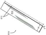
图8是根据一示例性实施方式的薄烧结材料带形式的烧结制品的透视图。Figure 8 is a perspective view of a sintered article in the form of a thin strip of sintered material according to an exemplary embodiment.
图9是根据另一示例性实施方式的来自生产线侧视图的示意图。Figure 9 is a schematic diagram from a side view of a production line according to another exemplary embodiment.
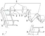
图10-11是根据其他示例性实施方式的生产线的透视图。10-11 are perspective views of production lines according to other exemplary embodiments.
图12是根据一示例性实施方式的生产线、或其一部分的示意图。Figure 12 is a schematic illustration of a production line, or a portion thereof, according to an exemplary embodiment.
图13是根据另一示例性实施方式的生产线、或其一部分的示意图。Figure 13 is a schematic illustration of a production line, or a portion thereof, according to another exemplary embodiment.
图14是根据另一示例性实施方式的生产线、或其一部分的示意图。Figure 14 is a schematic illustration of a production line, or a portion thereof, according to another exemplary embodiment.
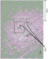
图15是在定位器板上烧结的薄陶瓷片材100倍放大的显微照片。Figure 15 is a photomicrograph at 100X magnification of a thin ceramic sheet sintered on a positioner plate.
图16是500倍放大率下与图15相同片材(大体为图15所示的虚线框内的图像)。Figure 16 is the same sheet as Figure 15 at 500x magnification (generally the image within the dotted box shown in Figure 15).
图17比较了使用本文所公开发明方法制成的部分烧结和完全烧结的带,覆盖白纸上的黑字。Figure 17 compares partially sintered and fully sintered tapes made using the inventive method disclosed herein, overlaying black lettering on white paper.
图18比较了使用本文所公开发明方法制成的部分烧结和完全烧结的带,覆盖黑纸上的白字。Figure 18 compares partially sintered and fully sintered tapes made using the inventive method disclosed herein, overlaying white lettering on black paper.
图19是使用本文所公开的本发明方法的薄陶瓷片材100倍放大的显微照片。Figure 19 is a photomicrograph at 100X magnification of a thin ceramic sheet using the inventive method disclosed herein.
图20是500倍放大率下与图19相同的片材。Figure 20 is the same sheet as Figure 19 at 500X magnification.
图21-22是根据示例性实施方式的带的表面扫描,其具有宽度方向(图21)和长度方向(图22)上的高度轮廓。21-22 are surface scans of a tape having height profiles in the width direction ( FIG. 21 ) and the length direction ( FIG. 22 ) according to an exemplary embodiment.
具体实施方式Detailed ways
在进入详细说明本发明的示例性实施方式的以下详细说明之前,应理解本发明的技术并不限于详细后面中所述或附图中所显示的细节或方法。例如,如本领域技术人员所理解的,与附图之一所示或者在涉及实施方式之一的文本中所述的实施方式相关的特征和属性可以适用于在另一附图所示或文本其他地方所描述的实施方式。Before proceeding to the following detailed description, which details exemplary embodiments of the invention, it is to be understood that the techniques of the present invention are not limited to the details or methodology described in the following detailed description or shown in the accompanying drawings. For example, features and attributes related to an embodiment shown in one of the drawings or described in the text referring to one of the embodiments may be applicable to the embodiments shown in another drawing or described in the text as understood by those skilled in the art. Implementations described elsewhere.
参考图3A-3B,生产线310包括炉系统312以及侧视图所示延伸到炉系统312中的工件(例如,带状物、带、网、线、材料),如带314。带314可围绕曲线或辊316布设,并向着炉系统312进行引导。根据一示例性实施方式,炉系统312包括通路318,所述通路318包括粘合剂烧尽位置B和/或用于带通过粘合剂烧尽位置B之后使得带314至少部分烧结的烧结位置C。在一些实施方式中,粘合剂烧尽位置B邻近烧结位置C,例如沿生产线310直接在烧结位置C的上方或下方,例如在烧结位置C上方或下方1米内、50厘米内、10厘米内。如进一步讨论,粘结剂烧尽位置B和烧结位置C的紧密设置减少了在进行烧结之前带314未被粘结剂结合的时间/长度。Referring to FIGS. 3A-3B ,
根据一示例性实施方式,对炉系统312的通路318进行定向以使得带314可以大体垂直延伸通过通路318,诸如不接触炉系统312至少一些区段的表面320,所述炉系统312的所述至少一些区段用来烧尽粘合剂(例如,粘合剂烧尽位置B)和/或使得带314至少部分烧结(例如,烧结位置C)。例如,通路318可以进行定向以使得带314可以大体垂直延伸,并且沿着相对于水平呈45°和135°之间(例如,60°和120°之间,如以90°±10°)取向的路径向上和/或向下移动。使得带314通过粘结剂烧尽位置B和/或烧结位置C而不使带314与烧结位置C的表面320和/或粘结剂烧尽位置B的表面322接触,被认为在由炉子系统312进行处理时,通过减少材料转移和/或刻痕或者由接触以其他方式对带314造成的成形,改进了带314的表面质量。According to an exemplary embodiment, the
根据一示例性实施方式,带314的第一区段是生坯带区段314A,其可以位于沿着生产线310的位置A。根据一示例性实施方式,生坯带区段314A包括通过有机粘合剂(例如聚乙烯醇缩丁醛、邻苯二甲酸二丁酯、聚碳酸烷基酯、丙烯酸聚合物、聚酯、硅酮等)结合的多晶陶瓷和/或矿物(例如氧化铝、氧化锆、锂石榴石(lithium garnet)、尖晶石)。在预期的实施方式中,生坯带区段314A可以包括以有机粘合剂结合的金属颗粒。在其它预期的实施方式中,生坯带区段314A可以包括由有机粘合剂结合的玻璃细粒(例如,高纯度二氧化硅细粒、硼硅酸盐、硅铝酸盐、碱石灰)或其它无机细粒。在预期的实施方式中,生坯带区段314A可以包含以有机粘合剂结合的玻璃陶瓷颗粒(例如,堇青石、LAS锂铝硅酸盐、纳米结构锂金属磷酸盐、钡长石)。根据一示例性实施方式,生坯带区段314A具有约0.01体积%至约25体积%的孔隙率,并且/或者无机颗粒的中值粒径为50纳米至1000纳米,并且布伦纳(Brunauer)、埃米特(Emmett)和特勒(Teller)(BET)表面积为2至30m2/g。在其他预期的实施方式中,上述材料可以通过无机粘合剂或其他粘合剂粘合,并且/或者上述材料可以是其他尺寸或具有其他孔隙率。According to an exemplary embodiment, the first section of
当生坯带区段314A通过粘结剂烧尽位置B时,炉系统312构造为由于氧化、挥发和/或交联将生坯带区段314A的粘合剂材料烧尽和/或烧成炭,例如烧尽大部分粘合剂和/或将大部分粘合剂烧成炭,例如至少90%粘合剂。根据示例性实施方式,生坯带区段314A以自支承的方式通过烧尽位置B,并且不需要和/或不接触烧尽位置B的表面322。在粘合剂烧尽位置B之外,带314不再是“生坯”,并且带314的第二区段是未结合带区段314B(例如,烧尽带区段,粘合剂烧成炭的带区段),其可以是未烧结的,但可能没有粘合剂或具有烧成炭的粘合剂。因为未结合带区段314B没有加工和/或未烧成炭的粘合剂,本领域的普通技术人员可以预期未结合带区段314B在其自身重量或未结合带区段314B下面的带314部分的重量下,由于缺乏粘合剂而简单崩塌或破裂。然而,申请人已经发现,尽管粘合剂被烧尽和/或烧成炭,但是如果对带314进行正确处理,例如如果对带314上的张力进行控制和/或如果在带314的无机材料(例如陶瓷细粒)进行至少部分烧结前带314并未弯曲和/或重新取向,则未结合带区段314B可以保持完好。As
仍然参考图3A,随后带314的未结合带区段314B部分进入和/或通过烧结位置C,并且炉系统312构造为使得未结合带区段314B的多晶陶瓷或其他无机材料至少部分烧结。例如,可以对多晶陶瓷细粒进行烧结,以使得细粒彼此结合或熔合,但是带314仍然包括大量的孔隙率(例如,至少10体积%、至少30体积%),其中“孔隙率”是指是未被无机材料如多晶陶瓷占据的带的体积部分。Still referring to FIG. 3A , unbonded tape segment 314B of
一旦至少部分烧结,带314的对应区段是至少部分烧结带区段314C。对至少部分烧结带区段314C进行部分并且不完全烧结可以将带314的强度增加至张可以对带314施加以促进随后的带314的成形的程度。根据一示例性实施方式,在张力下,发生带314的额外烧结以产生特别平坦或以其它方式成形的烧结制品(大体参见图5)。Once at least partially sintered, the corresponding section of
根据一示例性实施方式,生产线310进一步包括张力调节器324,所述张力调节器324例如通过与至少部分烧结带区段314C之间相互作用而影响带314中的张力。张力调节器324可以控制并分离在张力调节器324上方与下方的带314中的张力,以使得在张力调节器324的任一侧上的带314部分中的张力可以不同。在一些实施方式中,张力调节器324包括空气轴承,其中空气可以沿着带314移动通过生产线310的方向、或沿着与带314移动通过生产线310的方向相反的方向进行引导,例如,从而对带314中的张力进行调节。在其他实施方式中,张力调节器324包括夹辊,所述夹辊拉动或推动带314以影响带314中的张力。在其它实施方式中,张力调节器324可以是轮子(参见例如图12),其中轮子表面上的摩擦以及轮子的旋转影响带314中的张力。如所讨论的,带314中的张力可以用于在对带314进行烧结(例如在烧结区域C处或者沿着生产线310的其它位置进行烧结)时对带314进行成形。此外,通过张力调节器324向带314施加张力(其正量或负量)可以通过影响该区段中的张力而有助于将未结合带区段314B保持在一起。According to an exemplary embodiment, the
现在参考图3B,带314的温度可以沿带314长度方向改变,作为带314的特定部分沿着生产线310的位置的函数。生坯带区段314A在进入粘合剂烧尽位置B之前可经历第一温度,例如室温(例如,约25℃)。在粘合剂烧尽位置B附近,带314的未结合带区段314B所经受的温度可以高于生坯带区段314A所经受的温度,例如至少200℃,至少400℃。在烧结位置C附近、以及在烧结位置C处,带314所经历的温度可以高于粘合剂烧尽位置B附近的带314所经受的温度,例如在烧结位置C处为至少800℃、至少1000℃。位于沿生产线310经过烧结位置C的位置处的带314部分可经历低于烧结位置C处的带314部分和/或位于粘合剂烧尽位置B的带314部分的温度,例如经历室温。Referring now to FIG. 3B , the temperature of the
参见图4,炉系统410包括限定至少部分地延伸穿过炉系统410(例如完全穿过炉系统410的深度L1)的通路414的引导件412。在一些实施方式中,引导件412可以是可以由耐火材料形成的管或轴。根据一示例性实施方式,通路414是大体垂直定向的,以使得重力可以垂直牵拉、或沿着延伸通过通路414的细长工件(例如,柔性生坯带、带状物、线;参见图3A的整体带314)的长度以其他方式作用。在炉系统410的一些应用中,工件可以比通路414窄,并且可以位于通路414内,从而不接触引导件412的表面。炉系统可以在生产线、例如生产线310中使用。Referring to FIG. 4 , the furnace system 410 includes a
根据示例性实施方式,炉系统410的通路414具有延伸穿过炉系统410的深度尺寸L1、与深度尺寸L1正交的宽度尺寸(在图4延伸进入和延伸离开)、以及与深度尺寸L1和宽度尺寸正交的间隙尺寸L2。根据示意性实施方式,通路414的深度尺寸L1大于宽度尺寸,并且宽度尺寸大于间隙尺寸L2。根据示例性实施方式,间隙尺寸L2为至少1毫米,例如,至少2毫米、至少5毫米,以及/或者不超过500厘米。在一些实施方式中,宽度和间隙尺寸彼此相等,以使得通路414是圆柱形的。According to an exemplary embodiment, the
参见图4,炉系统410包括粘合剂烧尽位置B’以及烧结位置C’。烧尽位置B'构造为使得工件中的粘合剂材料燃烧,并且烧结位置C'构造为使得工件至少部分烧结。根据示例性实施方式,炉系统410包括热源416,例如,电阻加热元件、燃气或油燃烧器、或者其他热源。在一些实施方式中,热源416包围烧结位置C'的至少一部分、并且/或者与烧尽位置B'分开,例如通过可以由耐火材料形成的挡板或墙418与烧尽位置B'分开。根据一示例性实施方式,炉系统410的热源416位于烧尽位置B'的上方或下方。因此,热量可以从烧结位置C'协同地传递到粘合剂烧尽位置B'。在其他实施方式中,烧尽位置B可以具有与烧结位置C'分离的热源。Referring to FIG. 4, the furnace system 410 includes a binder burnout location B' and a sintering location C'. The burnout position B' is configured to burn the binder material in the workpiece, and the sintering position C' is configured to at least partially sinter the workpiece. According to an exemplary embodiment, the furnace system 410 includes a
在进入粘合剂烧尽位置B'之前,工件可经历第一温度,例如室温(例如,约25℃)。在粘合剂烧尽位置B'附近,工件所经历的温度可高于室温,例如,至少200℃、至少400℃。当工件靠近并通过烧结位置C'时,工件所经受的温度可高于在烧结位置B'附近工件所经受的温度,例如至少800℃、至少1000℃。在与粘合剂烧尽位置B'相反的烧结位置C'一侧上,超出烧结位置C'的工件的部分可经历较低的温度,例如经历室温。The workpiece may be subjected to a first temperature, such as room temperature (eg, about 25° C.), prior to entering the binder burnout position B′. Near the binder burnout location B', the temperature experienced by the workpiece may be higher than room temperature, eg, at least 200°C, at least 400°C. As the workpiece approaches and passes the sintering location C', the workpiece experiences a higher temperature than the workpiece near the sintering location B', for example at least 800°C, at least 1000°C. On the side of the sintering location C' opposite the binder burnout location B', the portion of the workpiece beyond the sintering location C' may experience a lower temperature, for example room temperature.
现在参见图5,如美国专利8,894,920中所述,可以生产3摩尔%的氧化钇稳定化的氧化锆(3YSZ)生坯陶瓷的铸件。在一示例中,从铸件切出2.5cm宽×5m长的材料生坯带512。将生坯带512缠绕在圆柱形辊514上,然后以2英寸/分钟的受控速率进料至炉系统516,如图5所示(同样参见炉系统410,如图4所示)。炉系统516的烧结位置C″保持在1200℃。粘合剂烧尽位置B″被隔离,并由氧化铝纤维板制成,以提供用于烧尽粘合剂的区域。粘合剂烧尽位置B″通过离开炉系统516的烧结位置C'的热气进行加热。Referring now to FIG. 5, castings of 3 mole percent yttria-stabilized zirconia (3YSZ) green ceramics can be produced as described in US Pat. No. 8,894,920. In one example, a 2.5 cm wide x 5 m long green strip of material 512 is cut from the casting. Green strip 512 was wound on
在所示构造510中,申请人已经发现10英寸长的粘合剂烧尽位置B″(在垂直方向上以长度显示)使得带512以高达约3英寸/分钟的速度成功进料。所示炉系统516的烧结位置C″是12英寸,导致烧结位置C”的总时间为约4到6分钟。在炉系统516的出口处,3YSZ带512'进行部分烧结,具有约0.65的相对密度。3YSZ带512'具有足够的强度用于处理,是柔性的,且厚度为约40微米。如图5所示,数米的烧结带512'已经在支承性塑料载体膜518上重新定向。In the
申请人已经发现,对于聚乙烯醇缩丁醛(PVB)粘合剂,粘合剂烧尽位置B″的温度应当在约200℃至600℃范围内。申请人已经发现,该粘合剂烧尽位置B″的长度足够还可以实现通过炉系统516的高速带速度,因为如果粘合剂烧尽位置B″太短,则粘合剂可能以过高的速率被去除,可能导致不受控制的粘合剂消除以及带512破损。此外,申请人已经发现粘合剂烧尽位置B″的长度与带512可以成功烧结情况下的速率相关。根据示例性实施方式,粘合剂烧尽位置B″的长度为至少2英寸和/或不超过50英寸,例如至少4英寸和/或不超过20英寸。在其他实施方式中,粘合剂烧尽位置B″可以具有在以上范围之外的长度。Applicants have found that for polyvinyl butyral (PVB) adhesives, the temperature at the adhesive burnout location B" should be in the range of about 200°C to 600°C. Applicants have found that the adhesive burnout Sufficient length of the burnout location B" also allows high speed belt speeds through the furnace system 516, because if the binder burnout location B" is too short, the binder may be removed at a rate that is too high, possibly resulting in uncontrolled Binder elimination and ribbon 512 breakage. Additionally, applicants have found that the length of the binder burnout site B" is related to the rate at which ribbon 512 can be successfully sintered. According to an exemplary embodiment, the binder burnout location B" has a length of at least 2 inches and/or no more than 50 inches, such as at least 4 inches and/or no more than 20 inches. In other embodiments, the binder burnout Only the position B" may have a length outside the above range.
仍然参考图5,在另一个示例中,使用构造510来生产和烧制带512(这次是氧化铝生坯陶瓷)。对带512进行浇铸的过程包括配料、研磨、除气(或脱气)、过滤、以及制造带。为了配料,将氧化铝粉末与包括粘合剂、分散剂、增塑剂和消泡剂的水基带铸造成分混合。所用成分由聚合物创新公司(Polymer Innovations)生产,包括基于丙烯酸的水溶性粘合剂。Still referring to FIG. 5 , in another example,
为了进行研磨,通过例如球磨、高剪切混合、摩擦研磨,振动研磨,辊研磨等方法在研磨机中对批料材料进行研磨并混合。研磨步骤使颗粒解聚集并形成均匀、良好分散的浆料。在一些实施方式中,申请人发现来自联合工艺公司(Union Process)的磨碎机(也称为搅拌式球磨机)可通过使得氧化铝粉末的聚集体或纳米聚集体瓦解而促进解聚集。申请人认为磨碎机由于在研磨过程中向材料输入高能量而具有优于其它研磨工艺和设备的优点,例如与其他技术相比,该研磨工艺能够在较短的时间内将该批料研磨成更小的粒度,例如,磨碎机的1至3小时相对于采用球磨的50至100小时。For milling, the batch material is ground and mixed in a mill by methods such as ball milling, high shear mixing, friction milling, vibratory milling, roller milling, and the like. The milling step deagglomerates the particles and forms a uniform, well dispersed slurry. In some embodiments, Applicants have discovered that an attritor (also known as an agitated ball mill) from Union Process can facilitate deagglomeration by disintegrating aggregates or nanoaggregates of alumina powder. Applicants believe that attritors have advantages over other grinding processes and equipment due to the high energy input to the material during grinding, such as the ability to grind the batch in a shorter time compared to other technologies to a smaller particle size, for example, 1 to 3 hours with an attritor versus 50 to 100 hours with a ball mill.
所用的一联合工艺磨碎机的总体积为750毫升(mL),工作体积/容积为250毫升。该容器装有130mL浆料和740g的2mm的99.9%纯氧化铝介质(即,研磨介质)。在研磨过程中,将容器水冷至15℃以避免过热、并减少溶剂的蒸发。首先以500转/分钟(rpm)对浆料进行5分钟的初始研磨以瓦解大聚集体,然后将速度增加至1300rpm并研磨1小时。在研磨结束时,将罐减速至170rpm,加入消泡剂以除去夹带的空气。然后,将浆料倾倒通过80-120目筛,以在除气之前从浆液中去除研磨介质。The combined process attritor used had a total volume of 750 milliliters (mL) and a working volume/volume of 250 mL. The vessel contained 130 mL of slurry and 740 g of 2 mm 99.9% pure alumina media (ie, grinding media). During milling, the vessel was water cooled to 15°C to avoid overheating and to reduce solvent evaporation. The slurry was initially ground at 500 revolutions per minute (rpm) for 5 minutes to break up large aggregates, then the speed was increased to 1300 rpm and ground for 1 hour. At the end of milling, the tank was slowed down to 170 rpm and antifoam was added to remove entrapped air. The slurry was then poured through an 80-120 mesh screen to remove grinding media from the slurry prior to degassing.
为了除气,例如在研磨之后,申请人发现研磨介质可以从浆料中滤出,并且可以使用真空将浆料脱气/除气以从经研磨的产物中除去所夹带的空气,否则所述经研磨的产物可能在混合物内包含气泡。除气可以用干燥器腔室和Mazerustar真空行星式混合器完成。可将浆料装入干燥器腔室中并进行高达10分钟的除气。初始除气后,可将浆料装入行星式混合器中并在真空下操作5分钟。申请人发现,替代性的除气程序(不使用Mazerustar混合器)是在干燥器腔室中使用更高的真空。For degassing, e.g. after grinding, applicants have found that the grinding media can be filtered out of the slurry and a vacuum can be used to degas/degas the slurry to remove entrapped air from the ground product that would otherwise be described. The ground product may contain air bubbles within the mixture. Degassing can be accomplished with a dryer chamber and a Mazerustar vacuum planetary mixer. The slurry can be loaded into the dryer chamber and degassed for up to 10 minutes. After initial degassing, the slurry can be charged to a planetary mixer and operated under vacuum for 5 minutes. Applicants have discovered that an alternative degassing procedure (without the use of a Mazerustar mixer) is to use a higher vacuum in the dryer chamber.
为了过滤,将浆料进行过滤以去除混合物中的任何大尺度污染物。例如,该污染物若不除去则可能会在烧结材料中以产生不利的光学性质。过滤可以用50微米、25微米、10微米或1微米的过滤器完成。该过滤器可以由例如尼龙、纤维或其他合适材料制成。For filtration, the slurry is filtered to remove any large scale contaminants in the mixture. For example, the contaminants may be present in the sintered material to produce unfavorable optical properties if not removed. Filtration can be done with 50 micron, 25 micron, 10 micron or 1 micron filters. The filter may be made of, for example, nylon, fiber or other suitable material.
对于带的制造步骤,将样品浇铸在厚度约50至150微米的硅酮涂布的


仍然参见图5,从如上所述浇铸的生坯上切下1.2米长×120微米厚×1.2厘米宽的带512并进行剥离。将带512缠绕到圆柱形辊514上。然后将带512以1英寸/分钟的受控速率进料至炉系统516中,如图5所示。带512具有足够的强度以在粘合剂烧尽期间在其自身重量下保持在一起。炉系统516的烧结位置C″保持在1100℃的温度下。在炉系统516的出口处,氧化铝带512'进行部分烧结,具有约0.7的相对密度。带512'的烧制厚度为约100微米。Still referring to Figure 5, a 1.2 meter long x 120 micron thick x 1.2 cm wide strip 512 was cut from the green body cast as described above and stripped. The belt 512 is wound onto a
参见图6A-6B,根据本文所公开的本发明方法和本文所公开的本发明设备制造的材料可以不同于根据常规方法制造的材料。根据一示例性实施方式,烧结制品610(例如片材、箔)包括第一表面612(例如,顶部、侧面)以及可以与第一表面612相反的第二表面614(例如,底部)。烧结制品进一步包括在第一表面612和第二表面614之间延伸的材料主体616。Referring to Figures 6A-6B, materials produced according to the inventive methods disclosed herein and the inventive devices disclosed herein may differ from materials produced according to conventional methods. According to an exemplary embodiment, a sintered article 610 (eg, sheet, foil) includes a first surface 612 (eg, top, sides) and a second surface 614 (eg, bottom), which may be opposite the
制品610的厚度T可以限定为第一表面612和第二表面614之间的距离。制品610的宽度(大致参见图8的烧结片材810的宽度W)可以限定为与厚度T正交的第一表面612或第二表面614中的一个表面的第一尺寸。制品610的长度(大致参见图8的烧结片材810的宽度L)可以限定为与厚度T和宽度正交的第一表面612或第二表面614中的一个表面的第二尺寸。根据示例性实施方式,烧结制品610是烧结材料的细长薄带。至少部分由于几何形状,一些这样的实施方式是柔性的,使得制品610能围绕心轴或卷轴弯曲(例如,直径为1米或更小、0.7米或更小),这对于制造、存储等是有利的。在其他实施方式中,烧结制品610可以是其他形状的(例如圆形、环形、套筒或管状形状),不具有恒定厚度等。The thickness T of the
根据示例性实施方式,制品610的长度大于制品610的宽度的2倍,如至少5倍、至少10倍、至少100倍。在一些实施方式中,制品610的宽度大于主体厚度T的两倍,例如至少5倍、至少10倍、至少100倍。在一些实施方式中,制品610的宽度为至少5毫米,例如至少10毫米、例如至少50毫米。在一些实施方式中,制品610的厚度T不超过2厘米,例如不超过5毫米,例如不超过2毫米,例如不超过1毫米,例如不超过500微米,例如不超过200微米。根据一示例性实施方式,当生坯带进入炉中并进行烧结时,烧结几乎均匀地发生;并且片材的长度、宽度和厚度可以减小至多约30%。这样,本文所公开的生坯带的尺寸可以比上述烧结制品所述尺寸大30%。薄带可使生产线能够快速运行,因为来自炉的热量可以快速穿透并烧结该带。另外薄带可以是柔性的,利于沿制生产线的方向弯曲和变化(例如,大致参见图11)。According to an exemplary embodiment, the length of the
根据示例性实施方式,如图6A的数码图像中所示且如图6B侧视图中概念性显示,烧结制品610基本未经抛光,以使得第一表面612和第二表面614中的一个表面或两者具有粒状轮廓,如当在显微镜下观察时尤为如此。粒状轮廓包括从主体616大体向外突出的细粒618,其相对细粒618之间的边界620处的表面凹陷部分具有至少25纳米和/或不大于100微米的高度H(例如,平均高度),如至少50纳米和/或不超过80微米的高度H。在其他实施方式中,高度H可以是其他尺寸。According to an exemplary embodiment, as shown in the digital image of FIG. 6A and shown conceptually in the side view of FIG. 6B , sintered
与从晶锭切下相反,粒状轮廓是将制品610烧结为薄带的烧结制品610制造过程的指标,并且相应的表面612、614基本没有抛光。另外,与抛光表面相比,粒状轮廓可以在一些应用(例如用于显示器的背光单元进行散射光)中为烧结制品610提供益处,增加用于涂层的更大粘附性的表面积或用于培养物生长的表面积。在预期的实施方式中,未抛光表面612、614的粗糙度为在沿制品长度的一个维度的10毫米距离上约10至约1000纳米,例如约15纳米至约800纳米。在预期的实施方式中,表面612、614中的一表面或两者的粗糙度为在沿单个轴的1cm的距离上约1nm至约10μm。The grain profile is indicative of the manufacturing process of the
相反,与烧结制品610具有相同材料的烧结制品710包括抛光表面712、714,其中细粒边界通常由于进行抛光而去除。在预期的实施方式中,根据本文公开的方法制造的烧结制品610可以进行抛光,如图7A-7B所示;例如,取决于制品的具体预期用途。例如,使用制品610作为基材可不需要非常光滑的表面,并且图6A-6B的未抛光表面可能是足够的;而该制品作为镜子或作为透镜的用途可能需要如图7A-7B所示进行抛光。然而,如本文所公开的,对于特别薄的制品或者薄且具有较大表面积的制品,可能难以进行抛光。In contrast, sintered
申请人认为,与图6A-6B的制品相比,从晶锭切下的烧结的陶瓷或其它材料的片材可能不具有容易识别的存在于其表面上的细粒边界。申请人进一步认为晶锭切割制品通常可以进行抛光以校正来自切割的粗糙表面。但是,申请人认为,对于非常薄的烧结的陶瓷或其他材料的制品,表面抛光可能特别困难或麻烦,随着该制品变薄且该制品的表面积变大,困难程度增加。然而,根据本公开技术制造的烧结制品可能较少由于这样的限制而受到限制,因为根据本发明技术制造的制品可以带的较长长度进行连续制造。此外,如本文所公开的炉系统的尺寸可以进行按比例缩放以适应和烧结更宽的制品,例如具有至少2厘米、至少5厘米、至少10厘米、至少50厘米宽度的制品。Applicants believe that a sheet of sintered ceramic or other material cut from an ingot may not have readily identifiable grain boundaries present on its surface, as compared to the article of FIGS. 6A-6B . Applicant further recognizes that boule cut articles can generally be polished to correct rough surfaces from cutting. Applicants believe, however, that surface polishing can be particularly difficult or cumbersome for very thin articles of sintered ceramic or other materials, with the degree of difficulty increasing as the article becomes thinner and the surface area of the article becomes larger. However, sintered articles made according to the disclosed techniques are likely to be less constrained by such limitations, since articles made according to the disclosed techniques can be manufactured continuously over longer lengths of tape. Furthermore, the size of the furnace system as disclosed herein can be scaled to accommodate and sinter wider articles, eg, articles having a width of at least 2 centimeters, at least 5 centimeters, at least 10 centimeters, at least 50 centimeters.
根据一示例性实施方式,烧结制品610具有粒状轮廓,并且在其表面612、614上具有一致的表面质量,这与背景技术中所讨论的使用定位器板制造的制品(其中,一侧通常通过与定位器板接触(例如,粘附和/或磨损)而有印记,而另一侧可能未曝露于定位器板)可能非常不同。在一些实施方式中,例如在烧结制品610为片材或带形式(大体参见图8所示的片材810)的情况下,表面一致性使得第一表面每平方厘米表面缺陷平均面积为第二表面的每平方厘米表面缺陷平均面积±50%内,其中“表面缺陷”是沿着相应表面尺寸至少15、10和/或5微米的磨损和/或粘附,例如,如图1-2所示,如第二表面的每平方厘米表面缺陷平均面积±30%内,例如,在第二表面的每平方厘米表面缺陷平均面积±20%内。According to an exemplary embodiment, the
根据一示例性实施方式,烧结制品610具有高表面质量,其可能与如背景技术中所讨论的使用定位器板所制造的制品(其中来自定位器板的粘附和/或磨损可能降低表面质量)非常不同。在一些实施方式中,例如,在烧结制品610为片材或带的形式(大体参见图8所示的片材810)的实施方式中,表面质量使得平均每平方厘米的第一和第二表面均具有少于15个、10个和/或5个尺寸大于15微米、10和/或5微米的表面缺陷,例如,平均每平方厘米少于3个这种表面缺陷,例如平均每平方厘米少于1个这样的表面缺陷。因此,根据本文公开的发明技术制造的烧结制品可具有相对高且一致的表面质量。申请人认为,烧结制品610高且一致的表面质量通过减少应力集中和/或裂纹引发的位点来促使制品610的强度增加。According to an exemplary embodiment, the
根据一示例性实施方式,制品610和生坯带的对应细粒材料包括多晶陶瓷。根据一示例性实施方式,制品610包括(例如,基本上由如下组成、至少50重量%由如下组成):氧化锆、氧化铝、尖晶石(例如MgAl2O4、ZnAl2O4、FeAl2O4、MnAl2O4、CuFe2O4、MgFe2O4、FeCr2O4)、石榴石、堇青石、莫来石、钙钛矿、烧绿石、碳化硅、氮化硅、碳化硼、二硼化钛、氮化硅铝(siliconalumina nitride)、和/或氧氮化铝。在一些实施方式中,制品610是金属。在其它实施方式中,制品610是由粉末细粒烧结的玻璃。在一些实施方式中,制品610是IX玻璃和/或玻璃陶瓷。本文所公开的材料可以是合成的。According to an exemplary embodiment, the
现在参考图8,在一些实施方式中,烧结制品是本文所公开材料的片材810(例如烧结带)形式的。片材810包括表面814(例如,顶部或底部)和与其相反的另一表面、以及在两表面814之间延伸的主体(通常参见图6A-6B的制品610的侧面612、614和主体616)。根据一个示例性实施方式,片材810的宽度W限定为与厚度T'正交的表面814中一个表面的第一尺寸。根据示例性实施方式,片材810具有至少两个大致垂直的纵向侧边缘812。片材810的长度L定义为与厚度T'和宽度W正交的顶部或底部表面814中的一个表面的第二尺寸。长度L可以大于或等于宽度W。宽度W可以大于或等于厚度T’。Referring now to FIG. 8, in some embodiments, the sintered article is in the form of a sheet 810 (eg, a sintered ribbon) of the materials disclosed herein.
根据示例性实施方式,厚度T'不大于500微米,如不大于250微米,如不大于100微米,和/或至少20纳米。根据一个示例性实施方式,片材810的表面积为至少10平方厘米,如至少30平方厘米,如至少100平方厘米,甚至在一些实施方式中超过1000、5000、或甚至10000平方厘米;或根据本文所公开几何形状的其它尺寸,例如关于制品610的实施方式。在一些实施方式中,片材810的宽度W小于其长度L的1/4、1/5、1/6、1/7、1/8、1/9、1/10、和/或1/20。该几何形状对于某些应用可能是特别有用的,例如将片材810用作直线型电池的基材和/或将片材810用作在烘箱中使碳纳米管生长的表面,其中片材810填充烤箱表面、但不填充烤箱的大量体积。According to an exemplary embodiment, the thickness T' is not greater than 500 microns, such as not greater than 250 microns, such as not greater than 100 microns, and/or at least 20 nanometers. According to an exemplary embodiment, the surface area of
根据示例性实施方式,片材810包括(例如,由以下材料形成、由如下材料组成、基本上由如下材料组成、超过50体积%由如下材料组成)选自多晶陶瓷和合成矿物的材料。在其它实施方式中,片材810包括如本文所公开的玻璃、金属或其他材料。此外,根据示例性实施方式,片材810的材料为烧结形式的以使得材料的细粒彼此熔合(大体参见图6A)。片材810可以具有粒状轮廓(大体参见图6A-6B)或者可以进行抛光(大体参见图7A-7B)。According to an exemplary embodiment,
例如,在一些实施方式中,片材810由中值粒径为50~1000纳米、且BET表面积为2~30m2/g的氧化铝粉末制成。片材810由99.5-99.995重量%的氧化铝和约100至约1000ppm的烧结添加剂(如氧化镁)的带式浇铸氧化铝粉末制成。在一些实施方式中,片材810是半透明的。当片材810厚度为500μm或更小时,片材810在约300nm至约800nm波长处的总透射率可以是至少30%的。在一些实施方式中,当片材810厚度为500μm或更小时,在约300nm至约800nm波长下穿过片材810的总透射率为约50%至约85%。在一些实施方式中,当片材810厚度为500μm或更小时,在约300nm至约800nm波长下穿过片材810的漫透射率为约10%至约60%。在设想的实施方式中,片材810在上述公开范围内的波长下、但具有其它厚度,例如本文公开的其它厚度的情况下,可以具有上述公开的透射率百分比。本文公开的除氧化铝之外的材料也可以导致该半透明的烧结制品。For example, in some embodiments, the
参考图9,生产线910包括生坯带922的源912、炉系统914、张力调节器916、918以及烧结带924的接收器920。根据一示例性实施方式,在可以进行单独制造时,生坯带922的源912可以是生坯带的一个卷922的形式。如图9所示,在一些实施方式中,将生坯带922引导至炉系统914的第一部分926中,例如通过引导通路928进行引导。如图9所示,在一些实施方式中,将生坯带922沿垂直轴引导通过炉系统914,以使得生坯带922不与炉系统的定位器板和/或表面接触。Referring to FIG. 9 ,
炉系统914的第一部分926可以包括粘合剂烧尽位置(大体参见图3的生产线的位置B)和用于使得带912部分烧结的位置(大体参见图3的生产线的位置C)。因此,离开第一系统914的第一部分926的带932可以是部分烧结的。通过炉系统914的第一部分926的带922中的张力可受张力调节器916影响,所述张力调节器916可使得张力调节器916沿生产线910的任一侧上的带922、932、924中的张力存在差别。如图9所示,在张力调节器916的下方,炉系统914包括第二部分930。The first section 926 of the
根据示例性实施方式,张力调节器916、918之间的带932、924中的张力可以大于并未在张力调节器916、918之间的带922、932、924中的张力。在一些实施方式中,当带932在炉系统914的第二部分930中烧结时,张力调节器916、918之间的提高的张力可以用于保持带932平坦。例如,部分烧结的带932可以具有足够柔性以通过在张力调节器932、918之间的带932中的张力进行弯曲和/或变平,同时由于部分烧结的结合,部分烧结的带932可以足够坚固以承受张力而不会破损。换言之,在炉系统914的第二部分930中,将部分烧结的带932烧结至最终密度,并保持在足够的张力下以使得片材、带或带材变平,消除可能在未约束烧结中出现的卷曲、弯曲、拱起等。例如,申请人发现1厘米宽的部分烧结的氧化锆或氧化铝带材能够承受大于1千克的张力,约20兆帕,而没有破损。According to an exemplary embodiment, the tension in the
因此,再次参见图8,在预期的实施方式中,片材810的未改性表面的平坦度为在沿着单轴(例如沿着片材810长度方向)的1cm的距离上约0.1μm至约50μm。该平坦度与本文所公开的材料的表面质量、表面一致性、大面积、薄厚度和/或材料性质结合可以使得片材、基材、烧结带、制品等特别适用于各种应用,例如用于显示器的坚硬覆盖片、高温基材、柔性隔膜和其他应用。Thus, referring again to FIG. 8 , in contemplated embodiments, the flatness of the unmodified surface of
由于在压力负荷下石榴石蠕变或松弛的能力有限,石榴石可能在石榴石进行制造之后难以重新成形。因此,根据常规方法,石榴石可能难以制造成薄且平坦的形式。为此,本领域技术人员通常将生坯主体夹在平坦的耐火表面之间,这通常会导致烧结制品两侧上的许多表面缺陷。因此,当制造如本文所公开的合成石榴石薄片材时,本公开的技术被认为是特别有用的。Due to the limited ability of garnets to creep or relax under pressure loads, garnets may be difficult to reshape after the garnets have been fabricated. Therefore, according to conventional methods, garnet may be difficult to manufacture in a thin and flat form. For this reason, those skilled in the art typically sandwich the green body between flat refractory surfaces, which often results in numerous surface defects on both sides of the sintered product. Accordingly, the techniques of the present disclosure are believed to be particularly useful when fabricating synthetic garnet flakes as disclosed herein.
参考图10,与图9的生产线910相似的生产线1010包括生坯带1022的源1012、具有两个分开部分1026、1030的炉系统1014、张力调节器1016、1018、以及烧结带1024的接收器1020。然而,对于生产线1010,生坯带在生产线1010上进行连续生产。此外,在烧结带1024从炉系统1014的第二部分1030中排出时,将烧结带1024切成条状物1032(例如,至少5厘米长、至少10厘米长,和/或不超过5米长、不超过3米长)。随后,条状物1032可进行堆叠、包装和运输。10, a
参见图11,生产线1110包括带1112(例如,生坯带)的源。源是带1112的卷轴1114形式的,其中带1112最初位于聚合物背衬1116(例如Mylar)上。当带1112大体水平地离开卷轴1114(例如,相对于水平方向在30°以内,相对于水平方向在10°以内)时,聚合物背衬1116在分离位置1118处从带1112撕下并且缠绕到单独的卷轴1120上。随后,带1112经过空气轴承1122,并且以受控量的下垂逐渐地重新取向至第一引导件1124中,所述第一引导件1124使得带1112大致垂直取向(例如,相对于垂直方向在30°内、相对于垂直方向在10°内)。Referring to FIG. 11 ,
呈生坯形式的带1112遵循着第一引导件1124向上移动至第一炉1126中(如图4所示,大体参见炉410)。在一些实施方式中,第一炉1126是将带1112的有机粘合剂烧成炭或烧尽以形成带1112的未结合区段的较低温度的炉。第一炉1126还可对所获得的带1112的未结合区段进行部分烧结以形成带1112的部分烧结区段1128。在通过第一炉之后,可以将带1112引导通过第二引导件1130。第一引导件1124和第二引导件1130使得带1112与通过第一炉1126的通路对准,使得带1112不与第一炉1126的表面接触,从而减少了与粘附和磨损相关的表面缺陷的数量。该带1112可能仍然具有一些缺陷,例如由于与错误颗粒接触造成的缺陷等。The belt 1112 in green form follows a
根据一示例性实施方式,在第二引导件1130之后,带的部分烧结区段1128布设在轮1132上。在一些实施方式中,轮1132具有低摩擦表面1134,部分烧结区段1128在所述低摩擦表面1134上滑动。轮1132与部分烧结区段1128之间的温差可有助于抑制轮1132与部分烧结区段1128之间的粘滞或粘附。根据一示例性实施方式,轮1132进行旋转以控制带1112中的张力,例如通过在轮1132的任一侧上为带1112提供不同的张力。According to an exemplary embodiment, after the second guide 1130 the partially sintered
例如,在一些情况下,轮1132以与带1112在轮1132上滑动的方向(例如,逆时针)相反的方向旋转(例如,顺时针),减小轮1132中带1112所来自一侧上的带1112中的张力,并增加轮1132中带1112离开一侧上的带1112中的张力,同时在带112的远端上通过张力调节器、如接收带1112的卷轴(大体参见图3和图9)、对带1112进行牵拉的机器臂(大体参见图10)、辊等保持所增加的张力。当带1112经过第二(可能温度更高)炉1136时,带1112中的张力在带1112完全烧结时使得带保持平坦。For example, in some cases,
如各种示例性实施方式中所示,生产线、设备以及所得烧结制品的构造和设置仅是说明性的。尽管在本公开中仅详细描述了一些实施方式,但是可以进行许多修改(例如,在各种元件的大小、尺寸、结构、形状和比例、参数的值、安装设置、材料的使用、颜色、取向上的变化)而不实质上背离本文所述主题的新颖性教导和优点。显示为一体形成的一些元件可以由多个部分或元件构成,元件的位置可以互换或以其他方式变化,并且离散元件的性质或数量或位置可以进行改变或变化。任何过程、逻辑算法或方法步骤的次序或顺序可根据替代性实施方式而变化或重新排序。可以对各种示例性实施方式的设计、操作条件和布置进行其他替代、修改、改变和省略,而不背离本发明的技术范围。As shown in the various exemplary embodiments, the construction and arrangement of the production line, equipment, and resulting sintered articles are illustrative only. Although only some embodiments have been described in detail in this disclosure, many modifications (for example, in size, dimension, structure, shape and proportion of various elements, values of parameters, installation settings, use of materials, colors, selection of upward changes) without materially departing from the novel teachings and advantages of the subject matter described herein. Some elements shown as integrally formed may be constructed of multiple parts or elements, the position of elements may be interchanged or otherwise varied, and the nature or number or position of discrete elements may be altered or varied. The order or sequence of any process, logical algorithm, or method steps may be varied or re-sequenced according to alternative implementations. Other substitutions, modifications, changes and omissions may be made to the designs, operating conditions and arrangements of the various exemplary embodiments without departing from the technical scope of the present invention.
* * ** * * *
再次参见图6,粒状轮廓包括相对于在细粒618之间的边界620处的表面凹陷部分以高度H(例如,平均高度)从主体616大体向外突出的细粒618,所述高度H为至少5纳米、例如至少10纳米、例如至少20纳米、例如至少25纳米,并且/或者不超过200微米、例如不超过100微米、不超过80微米、不超过50微米。Referring again to FIG. 6 , the grain profile includes
参见图12,用于部分烧结的生产线1210包括带1212(例如,生坯带)的源。源是带1214的卷轴1212形式,其中带1212最初位于聚合物背衬1216(例如Mylar)上。在一些这样的实施方式中,带1212从卷轴1214上离开并来到辊1244和真空抱筒(vacuum hug drum)1242上,然后聚合物背衬1216在分离位置1218处从带1212撕下,并且通过张紧装置1240张紧,经过辊1246,并卷绕到单独的卷轴1220上。带1212(没有背衬1216)随后进入炉1226的粘合剂烧尽区段B’”。在一些这样的实施方式中,带1212以大体垂直取向进入,并且/或者不与炉1226接触。Referring to Figure 12, a
在分离位置1218之后,呈生坯形式的带1212向下移动至炉1226中(如图4所示,大体参见炉410)。在一些实施方式中,炉1226的粘合剂烧尽区段B’”是将带1212的有机粘合剂烧成炭或烧尽以形成带1212的未结合区段的较低温度的炉。炉1226的较高温度部分C’”还可对所获得的带1212的未结合区段进行部分烧结以形成带1212的部分烧结区段1228,如图12中的离开炉1226所示。After
在通过炉1226之后,可以将带1212引导牵拉穿过用作第二引导件的辊1252。分离位置1218和排出辊1252可以使得带1212与通过炉1226的通路对准,使得带1212不与炉1226的表面接触,由此减少了与粘附和磨损相关的表面缺陷的数量。根据一示例性实施方式,分离位置1218和辊1252或炉1226的出口处或出口附近的其他引导件通常彼此垂直对齐,如沿垂直方向的15°内、10°内的线彼此垂直对齐。After passing through the
申请人注意到这样的带1212可能仍然具有一些缺陷,例如由于与错误颗粒、空气中的颗粒接触的缺陷等。排出辊1252可以由低摩擦聚合物材料制成。在在排出辊1252上经过之后,部分烧结的带可以缠绕在接收卷轴1250上。The applicant notes that such a
实施例1Example 1
用大致如图12所示的设备制造部分烧结的氧化锆带的90英尺长带。生坯带以类似于美国专利申请第8,894,920B2号的方式使用东曹株式会社(Tosho)(日本)的氧化锆粉末3YE进行制备。生坯带以大于约20厘米的宽度进行铸造,生坯带的厚度为约25微米。然后使用圆形剃刀刀片将该带手动划分为约15mm的宽度。使得生坯带从分离位置(参见图12中的分离位置1218)上的解送卷轴(pay-out spool)(大体参见图12中的卷轴1214)经过,并通过粘合剂烧尽烟道(参见图12中的烧尽区段B’”),通过过渡区(参见图12中的区域X’”),并进入更高温度的炉(例如,图12中的炉1226的区段C’”)。A 90 foot long strip of partially sintered zirconia tape was made using an apparatus generally shown in FIG. 12 . The green tape was prepared using zirconia powder 3YE from Tosho (Japan) in a manner similar to US Patent Application No. 8,894,920B2. The green strip was cast with a width greater than about 20 centimeters, and a green strip thickness of about 25 microns. The strip was then manually divided to a width of approximately 15mm using a round razor blade. The green tape is passed from a pay-out spool (see generally,
参考图12内容中实施例1,在分离位置1218处,陶瓷带1212从载体膜1216剥离。载体膜1216在张紧装置1240上运行并且到达卷取卷轴1220。粘合剂烧尽区B”’由来自炉区段C”’的热空气被动加热。用于实施例1的炉和粘合剂烧尽烟道中的通道由平行板材中的陶瓷纤维板制成,在板材之间具有0.125-0.5英寸的间隙(大体参见图4的间隙414和L2)。与间隙正交的宽度为约3.5英寸。粘合剂烧尽区的长度为约17英寸,并且粘合剂烧尽区下方的炉的长度为24英寸。Referring to Example 1 in the context of FIG. 12 , at a
申请人注意到,生坯带可以冷或热的方式插入(threaded)炉中。如果以热方式插入,则当对3YSZ(3摩尔%氧化钇稳定的氧化锆,四方相氧化锆多晶体“TZP”)、以及/或者氧化铝或具有相似烧结温度的其它陶瓷进行烧结或部分烧结时,申请人将炉的温度设定为接近1000℃,并且将带速度设定为1英寸/分钟。在以热方式插入之后,在带从炉底部出来后,温度可以升高,并且带速度也会增加。如果以冷方式插入,申请人建议在通过炉子并加热期间中以低速(0.25至1英寸/分钟)移动(即,输送、传输)带。Applicant notes that the green strip can be threaded into the furnace either cold or hot. If inserted thermally, when sintered or partially sintered 3YSZ (3 mole percent yttria stabilized zirconia, tetragonal zirconia polycrystalline "TZP"), and/or alumina or other ceramics with similar sintering temperatures , applicants set the temperature of the furnace to approximately 1000° C. and the belt speed to 1 inch/minute. After hot insertion, the temperature may increase and the belt speed increase after the belt comes out of the bottom of the furnace. If inserted cold, applicants recommend moving (ie conveying, conveying) the belt at a low speed (0.25 to 1 inch/minute) during passage through the oven and heating.
在该实施例1中,带以热方式插入,并且在插入之后,将炉加热并设定为1200℃,然后带以8英寸/分钟的速度移动通过炉。粘合剂烧尽烟道处于约100℃至400℃的温度下。将生坯带在炉内输送超过2.25小时,并且获得约90英尺连续长度的部分烧结带。In this Example 1, the tape was inserted hot, and after insertion, the furnace was heated and set to 1200°C, and the tape was moved through the furnace at a speed of 8 inches/minute. The binder burnout stack is at a temperature of about 100°C to 400°C. The green strip was conveyed in the furnace for over 2.25 hours and a continuous length of approximately 90 feet of partially sintered strip was obtained.
在宽度上的烧结收缩率为约9.5-10.5%。部分烧结的带在直径3.25英寸的卷轴上卷绕而不开裂。The sintering shrinkage across the width is about 9.5-10.5%. The partially sintered tape was wound on a 3.25 inch diameter spool without cracking.
实施例2Example 2
用类似于如图12所示的设备制造长度65英尺的部分烧结的氧化锆带,其中生坯带以类似于美国专利申请第8,894,920号的方式使用东曹株式会社(Tosho)(日本)的氧化锆粉末3YE进行制备。生坯带以大于约20厘米的宽度进行铸造。生坯带的厚度为约25微米。然后使用圆形剃刀刀片将生坯带手动划分为约52mm的宽度。Partially sintered zirconia tapes of 65 feet in length were produced with equipment similar to that shown in Figure 12, wherein the green tapes were oxidized by Tosho (Japan) in a manner similar to that of U.S. Patent Application No. 8,894,920. Zirconium powder 3YE was prepared. The green strip is cast at a width greater than about 20 centimeters. The thickness of the green tape was about 25 microns. The green strip was then manually divided to a width of approximately 52mm using a round razor blade.
接下来,使得生坯带从分离位置上的解送卷轴经过,并通过粘合剂烧尽烟道,通过过渡区,并进入更高温度主动加热的炉(例如,炉1226)。粘合剂烧尽区通过来自炉的加热空气被动加热。炉和粘合剂烧尽烟道中的通道(同样)由平行板材中的陶瓷纤维板制成,在板材之间具有1/8至1/2英寸的间隙。烟道的宽度为约31/2英寸。粘合剂烧尽区的长度约为17英寸,并且炉的长度为24英寸。Next, the green strip is passed from the unwind reel at the separation location, through the binder burnout flue, through the transition zone, and into a higher temperature actively heated furnace (eg, furnace 1226). The binder burnout zone is passively heated by heated air from the furnace. The channels in the furnace and binder burnout flues were (again) made of ceramic fiber boards in parallel plates with 1/8 to 1/2 inch gaps between the plates. The width of the flue is about 31/2 inches. The length of the binder burnout zone was approximately 17 inches and the length of the furnace was 24 inches.
在该实施例2中,在穿过之后,将炉加热至1000℃、1025℃、1050℃、1075℃、以及1100℃,同时带以2英寸/分钟的速度移动通过。粘合剂烧尽烟道处于约100℃至400℃的温度下。带在单独炉温下以各温度运行约1小时。炉运行超过6.5小时,并且使得超过连续65英寸(生坯)部分烧结带运行通过炉。In this Example 2, after passing, the furnace was heated to 1000°C, 1025°C, 1050°C, 1075°C, and 1100°C while the belt moved through at a speed of 2 inches/minute. The binder burnout stack is at a temperature of about 100°C to 400°C. The strips were run at each temperature for about 1 hour in a separate oven. The furnace was run for over 6.5 hours and over a continuous 65 inch (green body) partially sintered strip was run through the furnace.
整个带宽度的烧结收缩率取决于炉温,如下表1所列。发生了一些面外变形,表中烧结收缩率的变化部分是由于带的面外变形。The sintering shrinkage across the width of the strip depends on the furnace temperature, as listed in Table 1 below. Some out-of-plane deformation occurred, and the variation in sintering shrinkage in the table is partly due to out-of-plane deformation of the tape.
表1Table 1


在本文公开的各实施方式中,例如对于本文所公开的材料和系统,较高温度的炉的温度为至少800℃,例如至少1000℃。生坯带以至少1英寸/分钟,例如至少2英寸/分钟通过。例如,可以通过增加炉的长度来提高速率。通过其中的生坯带的收缩率为至少1.5%(例如,在一些实施方式中为至少2%)和/或不超过20%,例如不超过15%。In various embodiments disclosed herein, eg, for the materials and systems disclosed herein, the temperature of the higher temperature furnace is at least 800°C, eg, at least 1000°C. The green tape is passed at least 1 inch/minute, such as at least 2 inches/minute. For example, the rate can be increased by increasing the length of the furnace. The shrinkage of the green strip passing therethrough is at least 1.5 percent (eg, in some embodiments at least 2 percent) and/or no more than 20 percent, such as no more than 15 percent.
实施例3Example 3
用类似于如图12所示的设备制造长度60英尺的部分烧结的氧化锆带,其中生坯带以类似于美国专利申请第8,894,920号的方式使用东曹株式会社(Tosho)(日本)的氧化锆粉末3YE进行制备。生坯带以大于约20厘米的宽度进行铸造。生坯带的厚度为约25微米。然后使用圆形剃刀刀片将该带手动划分为约35mm的宽度。Partially sintered zirconia tapes of 60 feet in length were fabricated with equipment similar to that shown in Figure 12, wherein the green tapes were oxidized by Tosho (Japan) in a manner similar to that of U.S. Patent Application No. 8,894,920. Zirconium powder 3YE was prepared. The green strip is cast at a width greater than about 20 centimeters. The thickness of the green tape was about 25 microns. The strip was then manually divided to a width of approximately 35mm using a round razor blade.
使得生坯带从分离位置上的解送卷轴经过,并通过粘合剂烧尽烟道,通过过渡区,并进入炉。粘合剂烧尽区通过来自炉的加热空气被动加热。炉和粘合剂烧尽烟道中的通道由平行板材中的陶瓷纤维板制成,在板材之间具有1/8至1/2英寸的间隙。烟道的宽度为约31/2英寸。粘合剂烧尽区的长度约为17英寸,并且炉的长度为24英寸。The green strip is passed from the unwind reel at the separation position, through the binder burnout flue, through the transition zone, and into the furnace. The binder burnout zone is passively heated by heated air from the furnace. The channels in the furnace and binder burnout flue were made of ceramic fiber boards in parallel plates with a 1/8 to 1/2 inch gap between the plates. The width of the flue is about 31/2 inches. The length of the binder burnout zone was approximately 17 inches and the length of the furnace was 24 inches.
在该实施例3中,在穿过之后,将炉加热至1000℃、1150℃、以及1200℃,同时带以4英寸/分钟和6英寸/分钟的速度移动。粘合剂烧尽烟道处于约100℃至400℃的温度下。在各温度和相应带速度条件下将约10英尺的带在部分烧结后缠绕到直径为3.25的卷轴上,而没有断裂。In this Example 3, after the passes, the furnace was heated to 1000°C, 1150°C, and 1200°C while the belt moved at speeds of 4 inches/minute and 6 inches/minute. The binder burnout stack is at a temperature of about 100°C to 400°C. Approximately 10 feet of tape after partial sintering was wound onto a 3.25 diameter spool without breakage at each temperature and corresponding tape speed.
对烧结收缩率进行测定并列于下表2中,其中发生了一些面外变形,并且表中烧结收缩率的变化部分是由于带的面外变形。Sintering shrinkage was measured and reported in Table 2 below, where some out-of-plane deformation occurred and the variation in sintering shrinkage in the table is due in part to out-of-plane deformation of the tape.
表2Table 2

实施例4Example 4
用如图12所示的设备制造长度175英尺的部分烧结的氧化锆带。按如上所述制造氧化锆生坯带,但是使用圆形剃刀刀片将带手动划分为约15mm的宽度。使得带从分离位置上的解送卷轴经过,并通过粘合剂烧尽烟道,通过过渡区,并进入炉。以1100℃至1200℃的温度以及4、6、或8英寸/分钟的速度运行。粘合剂烧尽烟道处于约100℃至400℃的温度下,并且制造总体175英尺(生坯)的部分烧结带。A 175 foot length of partially sintered zirconia tape was fabricated using the apparatus shown in FIG. Zirconia green tapes were fabricated as described above, but the tapes were manually divided into widths of approximately 15 mm using a circular razor blade. The tape is passed from the unfeed reel at the separation position, through the binder burnout flue, through the transition zone, and into the furnace. Run at a temperature of 1100°C to 1200°C and a speed of 4, 6, or 8 inches per minute. The binder burnout stack was at a temperature of about 100°C to 400°C, and a total of 175 feet (green body) of partially sintered tape was produced.
对烧结收缩率进行测定并列于下表3中,其中发生了一些面外变形,并且表中烧结收缩率的变化部分是由于带的面外变形。当沿着带的长度1200mm进行测量时,以1200℃和8英寸/分钟制造的带在带的长度和宽度上具有总体约0.6mm的平均面外平坦度。Sintering shrinkage was measured and reported in Table 3 below, where some out-of-plane deformation occurred and the variation in sintering shrinkage in the table is due in part to out-of-plane deformation of the tape. The tape produced at 1200°C and 8 inches/minute had an overall average out-of-plane flatness of about 0.6 mm over the length and width of the tape when measured along the length of the tape, 1200 mm.
表3table 3

实施例5Example 5
用类似于如图12所示的设备制造长度147英尺的部分烧结的氧化锆带。氧化锆生坯带按如上所述进行制造,并且使用圆形剃刀刀片划分为约15mm。带按如上所述进行处理,不同的是,在穿过之后,将炉加热至并设定为1200℃,并且带以8英寸/分钟的速度移动。粘合剂烧尽烟道处于约100℃至400℃的温度下。使得生坯带移动通过炉超过3小时,并且获得超过147英尺连续长度(生坯)的部分烧结带。A 147 foot length of partially sintered zirconia tape was fabricated using equipment similar to that shown in FIG. A zirconia green tape was fabricated as described above and divided into approximately 15 mm using a round razor blade. The belt was processed as described above, except that after passing through, the furnace was heated and set to 1200°C and the belt moved at a speed of 8 inches per minute. The binder burnout stack is at a temperature of about 100°C to 400°C. The green strip was moved through the furnace over 3 hours and a partially sintered strip over 147 feet continuous length (green body) was obtained.
参见图13,用于部分烧结的生产线1310包括部分烧结带1312的源。源是部分烧结带1312的卷轴1314形式,其中带1312可以具有夹层材料。当带1312从卷轴1314上离开并来到辊1342时,高温材料的板材1346形成炉1326中的狭窄的通道。Referring to FIG. 13 , a
带1212随后进入炉1326,带1312大致垂直并且/或者不与触炉接触并且/或者沿炉的中心部分不与触炉接触。在预期的实施方式中,带的边缘可以与炉中的引导件或表面接触,但是稍后可以移除以提供带的低缺陷中心部分,如本文所公开的。在一些这样的实施方式中,带的纵向边缘包括切割标记,如激光或机械标记。The
在通过炉1326之后,可以将最终烧结的带1329牵拉通过张紧装置1340。输入辊1342和张紧装置1340与穿过炉1326的通道大致线性对齐,以使得带1312不与炉1326的表面接触,在一些这样的实施方式中,由此如本文文所述减少了与粘附和磨损相关的表面缺陷的数量。在通过张紧装置1340之后,使得最终烧结的带通过两个辊1344,并且通过传输装置1360(例如,辊、轴承、履带)。在传输装置1360之后,最终的烧结带可以在使用夹层材料的情况下卷绕或在不用夹层材料的情况下卷绕。After passing through
参见图14,用于部分烧结的生产线1410包括部分烧结带1412的源。源是部分烧结带1414的卷轴1412形式的,其中带1412可以具有夹层材料。带1412从卷轴1414上离开时,带1212随后进入炉1426,并且带1412是大致垂直取向的。在烧结过程中,张紧器(例如,重物1460,辊)附接到部分烧结的带上以在烧结期间对带进行牵拉以及/或者使得带保持平坦。在预想的实施方式中,重物1460可以是带本身的一段长度。Referring to FIG. 14 , a production line 1410 for partial sintering includes a source of partially sintered
令人惊讶的是,如上所述,申请人已发现生坯带的短长度以及烧尽的粘合剂可以承受一些张力,而不会使带瓦解。具有烧尽的粘合剂的区段在进入较高温炉之前的拉伸强度仅为相同材料并且由相同尺寸以及组成的生坯带形成的理想地完全烧结带的拉伸强度的一部分,例如小于20%,如小于10%,诸如小于5%,但仍为正值,如至少0.05%。Surprisingly, as noted above, applicants have found that the short length of the green tape and the burned-out binder can withstand some tension without the tape collapsing. The tensile strength of the section with burned-out binder before entering the higher temperature furnace is only a fraction of that of an ideally fully sintered tape formed from a green tape of the same material and size and composition, e.g. less than 20%, such as less than 10%, such as less than 5%, but still positive, such as at least 0.05%.
实施例6Example 6
如图1所述制造宽度15mm(生坯)的部分烧结带。然后将一卷15mm宽(生坯)、约25微米厚(生坯)的部分烧结带放在类似于如图13所示的系统1310(例如,第二炉,第二烧结位置)的设备上。陶瓷板材1346由碳化硅制成。板材之间的间隙为2至8毫米,板材的宽度为4英寸。炉的外部尺寸是21英寸长。将炉加热至1400℃(例如比实施例1的炉高至少100℃,例如,至少200℃以上、400℃以上)。A partially sintered strip with a width of 15 mm (green body) was produced as described in FIG. 1 . A roll of partially sintered tape 15 mm wide (green body) and approximately 25 microns thick (green body) is then placed on equipment similar to the
在实施例6中,部分烧结带(来自实施例1)以大于1英尺/分钟的速度用手快速插入1400℃的炉中。从卷轴1314提供足够的带,通过两个辊1344并且通过传输装置1360,使得带1312缠绕在张紧装置1340上。In Example 6, the partially sintered tape (from Example 1) was rapidly inserted by hand into a 1400°C furnace at a speed greater than 1 ft/min. Sufficient tape is provided from
在插入后,带以2英寸/分钟的速度运行。通过张紧装置1340将小于50克的张力施加到进行烧结的带上。制造约9英寸的致密的最终烧结带(例如,参见图17-22的完全烧结带2010)。该带是半透明的,如果放置文本与该带接触(参见图17-18的完全烧结带2010并与图17-18的部分烧结带2012进行比较),则可以通过该带阅读文本。该带确实具有光散射造成的一些白色雾度,可能来自微小孔隙率(例如,小于1%(如小于0.5%)并且/或者至少为0.1%的孔隙率)。After insertion, the belt runs at 2 inches/minute. A tension of less than 50 grams is applied by the
横向带收缩率约为24%。相同类型流延成型带的分批烧制材料具有约23%±约0.5%的烧结收缩率。尽管用于本实验的部分烧结带具有一些平面外变形,但在最终烧结之后,所述带在带运动方向上是平坦的。交叉网(带)方向存在一些“C形”卷曲。通过光学显微镜以100倍放大检查完全烧结带的1cm×1cm的面积。对最终烧结带的两面进行检查。没有发现定位器板典型的粘合或磨损缺陷。The transverse tape shrinkage was about 24%. Batch fired material of the same type of tape cast tape had a sinter shrinkage of about 23% ± about 0.5%. Although the partially sintered belt used for this experiment had some out-of-plane deformation, after final sintering the belt was flat in the direction of belt motion. There are some "C-shaped" curls in the cross web (ribbon) direction. A 1 cm x 1 cm area of the fully sintered tape was examined by an optical microscope at 100X magnification. Both sides of the final sintered strip are inspected. No bonding or wear defects typical of locator plates were observed.
如图15所示,最终烧结带可以弯曲至小于约2.5厘米的半径。As shown in Figure 15, the final sintered ribbon can be bent to a radius of less than about 2.5 centimeters.
实施例7Example 7
使用与图14所示类似的第二阶段烧结装置。炉仅约有4英寸高,有一个2英寸的热区。使用以类似于实施例3所述的方式制造的30毫米宽(生坯)的部分烧结带。在进行部分烧结之前,带为约25微米厚。将部分烧结的带卷置于炉上,其中炉在炉的顶部和底部绝热件(insulation)中具有3/16英寸和3.5英寸宽的狭窄间隙以使带通过。将带以冷方式穿过间隙并附接7.5克的重物(大体参见图14)。将炉加热到1450℃,当炉达到1450℃时开始带移动。带以0.5英寸/分钟的速度从顶部到底部运行。制成约18英寸的完全烧结的烧结氧化锆带。氧化锆带是半透明的。在实施例7中,对于4英寸的炉,带以及其完全烧结部分比炉长。参见图15-16,为了上下文和比较的目的,生坯带(3摩尔%的氧化钇稳定的氧化锆)按上述实施例中所述进行制造,并使用常规烧结工艺进行烧结,包括使用氧化铝定位器板以在烧结期间支承生坯从而形成陶瓷带3010。如图15所示,在100倍放大率下可以看到由于来自定位器板的粘附和磨损引起的表面缺陷。许多粘附或磨损引起的缺陷形成了烧结片材中的针孔,因为片材非常薄,为大约25微米。如图15所示,由于来自定位器板的粘附和磨损而产生的缺陷通常是沿彼此的共同方向上的椭圆形(oblong)。A second stage sintering apparatus similar to that shown in Figure 14 was used. The stove is only about 4 inches tall with a 2 inch hot zone. Partially sintered strips of 30 mm width (green body) produced in a manner similar to that described in Example 3 were used. Before partial sintering, the tape was about 25 microns thick. The partially sintered coils were placed on a furnace with narrow gaps of 3/16 inch and 3.5 inches wide in the top and bottom insulation of the furnace to pass the ribbon through. The belt is passed cold through the gap and a 7.5 gram weight is attached (see generally Figure 14). The furnace was heated to 1450°C and the belt movement was started when the furnace reached 1450°C. The belt runs from top to bottom at a speed of 0.5 in/min. Fully sintered sintered zirconia tapes of about 18 inches were made. The zirconia tape is translucent. In Example 7, for a 4 inch furnace, the strip and its fully sintered portion are longer than the furnace. 15-16, for context and comparison purposes, a green tape (3 mole percent yttria-stabilized zirconia) was fabricated as described in the above examples and sintered using a conventional sintering process, including the use of alumina The locator plate is used to support the green body during sintering to form the
如上所讨论的,由定位器引起的缺陷通常是由与定位器板接触的生坯带的烧结收缩所引起的表面特征,其中在烧结收缩期间,陶瓷在整个定位器板上拖拽其自身部分。结果是所获得的烧结制品的受支承侧具有从定位器板的耐火材料转移至烧结制品的表面缺陷(例如拖拽槽、烧结碎屑、杂质斑块等),以及定位器从烧结制品抽出材料而在该处形成的表面中的凹陷。当陶瓷制品具有沉积于其上的薄膜时,使该定位器缺陷最小化是重要的。如果一个或多个薄膜的层厚与定位器缺陷尺寸类似,则薄膜会具有针孔或者具有穿过薄膜层的定位器缺陷。As discussed above, defects caused by positioners are usually surface features caused by sintering shrinkage of the green strip in contact with the positioner plate, wherein during sintering shrinkage the ceramic drags parts of itself across the positioner plate . The result is that the supported side of the obtained sintered product has surface defects (such as drag grooves, sinter debris, impurity patches, etc.) transferred from the refractory material of the positioner plate to the sintered product, and the positioner draws material from the sintered product And a depression in the surface is formed there. Minimizing this locator defect is important when the ceramic article has a thin film deposited thereon. If one or more films have a layer thickness similar to the locator defect size, the film will either have a pinhole or have a locator defect through the film layers.
将图15-16的陶瓷带3010与使用本公开的技术制造的图17-22的陶瓷带2010进行比较;特别是如图19-20所示,其中分别为图15-16的相同放大率100X和500X下,并且来自以与用于图15-16的带的相同方式制造的生坯带。更具体地说,如本文所公开的,陶瓷带2010进行连续烧结,在1400℃下以2英寸/分钟的速率运行通过具有碳化硅中心通道的如实施例所述的第二炉。比较陶瓷带3010和陶瓷带2010,两种带显示出了在表面上的各种铸造痕迹,例如细长滚动条纹和倾斜(丘/谷)。陶瓷带3010显示出许多涉及定位器的缺陷:结合的颗粒,抽出和定位器-拖曳缺陷,例如,由于在收缩带拖拽经过定位器表面时的表面刨削,定位器拖曳在区域中产生了特征损伤图案,如本文所讨论。Compare the
参见图15-16和图19-20,在其表面的光学检查(参见图15和19)中,在100×处容易地观察到其截面尺寸大于5μm的结合颗粒。更具体地说,在整个约8cm2的面积上,在使用本文公开技术烧结的陶瓷带2010的表面上观察到一个这样的颗粒,而在约8cm2的相等面积上,在陶瓷带3010表面上观察到8个这样的颗粒.申请人认为陶瓷带3010由于与定位器接触而具有更多的结合颗粒,而陶瓷带2010具有较少数量的结合表面颗粒,后者可能是由于在炉内气氛中的颗粒粘附而造成的。在使用过滤器或其他方法去除或减少炉内气氛中的颗粒的未来的方法实施方式中,陶瓷带2010上的这种较少数量的结合表面颗粒可进一步减少。Referring to Figures 15-16 and Figures 19-20, in optical inspection of their surfaces (see Figures 15 and 19), bound particles with cross-sectional dimensions larger than 5 μm were easily observed at 100×. More specifically, one such particle was observed over an entire area of about 8 cm on the surface of ceramic tape2010 sintered using the techniques disclosed herein, and over an equal area of about 8cm on the surface of
根据一示例性实施例,根据本公开制造的带在其每8cm2表面上平均具有少于5个的截面尺寸大于5μm的结合颗粒,例如少于3个这样的颗粒,例如少于2个这样的颗粒。According to an exemplary embodiment, a tape manufactured according to the present disclosure has on average less than 5 bound particles having a cross-sectional dimension greater than 5 μm, such as less than 3 such particles, such as less than 2 such particles, per 8cm of its surface. particle.
根据一示例性实施例,如本文所公开的,烧结陶瓷片材具有小于50微米的厚度以及少于10个的针孔,其横截面积为至少1平方微米(或者,如果表面积小于一平方微米,则在整个表面上少于10个针孔),在整个表面上平均每平方毫米的表面,例如少于5个针孔,少于2个针孔,甚至在整个表面上平均每平方毫米少于1个针孔。According to an exemplary embodiment, the sintered ceramic sheet, as disclosed herein, has a thickness of less than 50 microns and less than 10 pinholes with a cross-sectional area of at least 1 square micron (or, if the surface area is less than one square micron , then less than 10 pinholes over the entire surface), averaged over the entire surface per square millimeter of the surface, such as less than 5 pinholes, less than 2 pinholes, or even less than an average of per square millimeter over the entire surface in 1 pinhole.
参考图19-20,陶瓷带19具有粒状表面,所述粒状表面具有凸起2014。凸起具有大约100微米或更多的最长尺寸。凸起通常是椭圆形的,如具有大体上彼此相同方向的主轴,如90%在方向D的15°内,例如90%在方向D的10°内。凸起可以区别于定位器引起的表面缺陷(例如磨损和粘附),因为凸起通常平滑滚动并且从邻接表面连续弯曲,与限定为或包括表面上的不相交的或不连续的边界(其是由定位器引起的粘附颗粒或磨损的特征)不同。凸起可以是本文所公开的至少一些过程的标记,例如由于较少限制的烧结过程的标记。其他实施方式可以不包括这种凸起,例如,如果带在烧结过程中轴向和横向张紧,这可以通过张紧器(例如辊、履带、轮子、机械张紧器、或其他这样的元件)来实现。Referring to FIGS. 19-20 , the ceramic tape 19 has a grained surface with
现在参考图21-22,根据本文公开的方法制造了陶瓷带4010,而无需定位器板。带4010的材料是3摩尔%氧化钇稳定的氧化锆,四方相氧化锆多晶“TZP”。带的宽度在12.8至12.9mm之间。所示部分是来自22英寸长片的带。带的厚度是约22微米。另外,白斑是扫描仪不能识别的标记在带上的标记物。Referring now to FIGS. 21-22, a
为了比较目的,带在线下方是完全烧结的,而在虚线L上方仅仅是部分烧结的。SEC1、SEC2、SEC3、SEC4是陶瓷带4010的顶部表面的轮廓。轮廓显示出带具有一些围绕纵轴(在图21中示出为X轴)的“C形”曲率。如本文所公开的,在张力下,通过完全烧结减少带中的拱起。可以看出,带的最大高度降低约100%,从约1.68mm降低到0.89至0.63mm之间。申请人相信,通过本方法和/或其它方法改进,例如增加张力或改变工艺速度,平放在平坦表面上的完全烧结带的最大高度将小于1.5mm(如小于1mm,如小于0.7mm,如理想地小于约100微米),例如,对于宽度为约10至15mm的带来说。For comparison purposes, the ribbon is fully sintered below the line and only partially sintered above the dotted line L. FIG. SEC1 , SEC2 , SEC3 , SEC4 are the contours of the top surface of the
在预期的实施方式中,本文所述带可以缠绕在卷轴上,如图所示,以形成带的一个卷。卷轴的直径可以为至少约0.5cm、如至少约2.5cm,以及/或者不大于1m,带的长度为至少1m、如至少10m,并且具有如本文所述的宽度和厚度,并且/或者如至少10mm和/或不大于20cm的宽度和至少10微米和/或不大于500微米、如不大于250微米、如不大于100微米、如不大于50微米的厚度。In contemplated embodiments, the tape described herein may be wound on a spool, as shown, to form a roll of tape. The diameter of the reel may be at least about 0.5 cm, such as at least about 2.5 cm, and/or not greater than 1 m, the length of the strip is at least 1 m, such as at least 10 m, and has a width and thickness as described herein, and/or as at least A width of 10 mm and/or not greater than 20 cm and a thickness of at least 10 microns and/or not greater than 500 microns, such as not greater than 250 microns, such as not greater than 100 microns, such as not greater than 50 microns.
本申请还涉及以下项目。This application also relates to the following items.
1.一种生产线,所述生产线包括:1. A production line, said production line comprising:
包括生坯区段的带,所述生坯区段包含通过有机粘合剂结合的无机材料细粒;以及a belt comprising green body sections comprising fine particles of inorganic material bound by an organic binder; and
一种炉,其包括:A furnace comprising:
限定通路的引导件,其中所述通路包括粘合剂烧尽位置以及烧结位置,以及a guide defining a passageway, wherein the passageway includes a binder burnout location and a sintering location, and
加热器,所述加热器实现了在通路的烧结位置至少300℃的温度;a heater that achieves a temperature of at least 300°C at the sintered location of the via;
其中,粘合剂烧尽位置使得生坯区段中的有机粘合剂烧成炭或燃烧,以形成尚未烧结但已经烧成炭或没有粘合剂的带的未结合区段;wherein the binder burnout position causes the organic binder in the green section to char or burn to form an unbonded section of the tape that has not been sintered but is charred or binder-free;
其中,烧结位置使得无机材料至少部分烧结以形成带的至少部分烧结区段;并且wherein the sintering location is such that the inorganic material is at least partially sintered to form an at least partially sintered section of the belt; and
其中,未结合区段支承了与之物理连接且邻近的带的重量。Therein, the unbonded section supports the weight of the strap to which it is physically connected and adjacent.
2.如项目1所述的生产线,其特征在于,所述炉是第一炉,所述生产线进一步包括:2. The production line according to item 1, wherein the furnace is the first furnace, and the production line further comprises:
第二炉,其中第二炉对至少部分烧结的带的无机材料进行进一步烧结以形成完全烧结的制品;以及a second furnace, wherein the second furnace further sinters the inorganic material of the at least partially sintered strip to form a fully sintered article; and
张力调节器,其中所述张力调节器影响所述带中的张力以促进在第二炉的进一步烧结期间对至少部分烧结的区段进行成形。A tension regulator, wherein the tension regulator affects the tension in the belt to facilitate shaping the at least partially sintered section during further sintering in the second furnace.
3.如项目1所述的生产线,其特征在于,对所述炉的通路进行定向以使得带大体垂直地通过炉。3. The production line according to item 1, characterized in that the passage of the furnace is oriented so that the belt passes through the furnace substantially vertically.
4.如项目1所述的生产线,其特征在于,所述通路沿直线路径延伸。4. The production line according to item 1, characterized in that the passageway extends along a rectilinear path.
5.如项目4所述的生产线,其特征在于,所述通路具有延伸穿过炉的深度尺寸、与深度尺寸正交的宽度尺寸、以及与深度尺寸和宽度尺寸正交的间隙尺寸,其中,深度尺寸大于宽度尺寸,并且宽度尺寸大于间隙尺寸。5. The production line of item 4, wherein the passageway has a depth dimension extending through the furnace, a width dimension orthogonal to the depth dimension, and a gap dimension orthogonal to the depth dimension and width dimension, wherein, The depth dimension is greater than the width dimension, and the width dimension is greater than the gap dimension.
6.如项目5的生产线,其特征在于,所述间隙尺寸为至少1毫米。6. The production line according to item 5, characterized in that said gap dimension is at least 1 mm.
7.如项目1所述的生产线,其特征在于,所述加热器对炉的粘合剂烧尽位置以及烧结位置进行加热。7. The production line according to item 1, wherein the heater heats the binder burnout position and the sintering position of the furnace.
8.如项目7所述的生产线,其特征在于,所述加热器定位成邻近烧结位置且至少部分围绕烧结位置,但是与粘合剂烧尽位置垂直间隔开。8. The production line of item 7, wherein the heater is positioned adjacent to and at least partially surrounding the sintering location, but vertically spaced from the binder burnout location.
9.如项目1所述的生产线,其特征在于,所述引导件包含耐火材料。9. The production line according to item 1, characterized in that said guides comprise a refractory material.
10.一种对带进行烧结的方法,所述方法包括以下步骤:10. A method of sintering a ribbon, said method comprising the steps of:
(a)使得带的生坯区段移动通过炉的第一炉位置,所述生坯区段包含通过有机粘合剂支承的无机细粒;(a) moving a green section of the belt, the green section comprising inorganic fines supported by an organic binder, through a first furnace position of the furnace;
(b)在生坯通过第一炉位置时,将生坯区段中的有机粘合剂烧尽或烧成炭,以形成带的未结合区段;(b) burning out or charring the organic binder in the green body section as the green body passes through the first furnace station to form the unbonded section of the tape;
(c)使得未结合区段移动通过第二炉位置;以及(c) moving the unbonded segment through the second oven position; and
(d)随着未结合区段通过第二炉位置,至少部分烧结无机细粒,以形成带的至少部分烧结区段,(d) at least partially sintering the inorganic fines as the unbonded section passes through the second furnace position to form at least partially sintered sections of the belt,
其中,在进行使得未结合区段移动通过第二炉位置的步骤的时候,无需对带的未结合区段进行支承的定位器板。Therein, there is no need for a locator plate supporting the unbonded section of the belt while the step of moving the unbonded section through the second oven position is performed.
11.如项目10所述的方法,其特征在于,在将生坯区段中的有机粘合剂烧尽或烧成炭的过程中,所述带的生坯区段在生坯区段通过第一炉位置时不与炉表面接触。11. The method according to
12.如项目11所述的方法,其特征在于,在使得无机细粒至少部分烧结的步骤期间,所述带的未结合区段在该未结合区段通过第二炉位置时不与炉表面接触。12. The method according to item 11, wherein during the step of at least partially sintering the inorganic fine particles, the unbonded section of the tape does not contact the furnace surface as the unbonded section passes through the second furnace position touch.
13.如项目12所述的方法,其特征在于,无机细粒是选自多晶陶瓷和合成矿物的材料的细粒。13. The method according to
14.如项目12所述的方法,其特征在于,所述带是整体的,以使得生坯区段、未结合区段、以及至少部分烧结的区段在所述方法的步骤(a)至(d)期间是彼此邻接的。14. The method of
15.如项目10所述的方法,其特征在于,使得无机细粒至少部分烧结的步骤期间,当未结合区段通过第二炉位置时,未结合区段是自支承的。15. The method of
16.如项目10所述的方法,其特征在于,当生坯区段通过第一炉位置时,生坯区段大体垂直取向,以使得未结合区段支承与之物理连接且垂直相邻的带的重量。16. The method of
17.一种烧结制品,其包括:17. A sintered product comprising:
第一表面、第二表面、以及在第一表面和第二表面之间延伸的材料主体,其中,第二表面在与第一表面相反的烧结制品反面,以使得烧结制品的厚度限定为第一表面和第二表面之间的距离,烧结制品的宽度限定为与厚度正交的第一表面或第二表面中一个表面的第一尺寸,并且烧结制品的长度限定为与烧结制品厚度和宽度正交的第一表面或第二表面中一个表面的第二尺寸,A first surface, a second surface, and a body of material extending between the first surface and the second surface, wherein the second surface is opposite the sintered article from the first surface such that the sintered article has a thickness defined as the first The distance between the surface and the second surface, the width of the sintered product is defined as the first dimension of one of the first surface or the second surface that is normal to the thickness, and the length of the sintered product is defined as being normal to the thickness and width of the sintered product the second dimension of one of the intersecting first or second surfaces,
其中,材料主体包含无机材料;Wherein, the material body includes inorganic materials;
其中,烧结制品的长度大于或等于烧结制品的宽度,并且其中,烧结制品是薄的以使得烧结制品的宽度大于烧结制品的厚度的5倍,烧结制品的厚度为不超过1毫米;wherein the length of the sintered product is greater than or equal to the width of the sintered product, and wherein the sintered product is thin such that the width of the sintered product is greater than 5 times the thickness of the sintered product, and the thickness of the sintered product is not more than 1 mm;
其中,烧结制品基本未抛光以使得第一和第二表面各自具有粒状轮廓;wherein the sintered article is substantially unpolished such that the first and second surfaces each have a grainy profile;
其中,烧结制品具有高表面质量以使得第一表面和第二表面都具有至少一平方厘米的下述区域:所述区域具有少于十个的粘附或磨损造成的尺寸大于五微米的表面缺陷,所述高表面质量有利于所述烧结制品的强度;和wherein the sintered article has a high surface quality such that both the first surface and the second surface have an area of at least one square centimeter having less than ten adhesion or wear-induced surface defects greater than five microns in size , the high surface quality contributes to the strength of the sintered product; and
其中,所述烧结制品在第一表面和第二表面上都具有一致的表面质量,使得第一表面每平方厘米的由粘附或磨损导致的尺寸大于五微米的表面缺陷的平均面积为第二表面每平方厘米的由粘附或磨损导致的尺寸大于五微米的表面缺陷的平均面积±50%之内。Wherein, the sintered product has a consistent surface quality on both the first surface and the second surface, so that the average area of surface defects with a size greater than five micrometers caused by adhesion or wear per square centimeter of the first surface is the second Within ± 50% of the average area per square centimeter of the surface of surface defects caused by adhesion or abrasion that are larger than five microns in size.
18.如项目17所述的烧结制品,其特征在于,粒状轮廓包括相对于各细粒之间边界处的第一表面和第二表面的凹陷部分高度范围为25纳米至150微米的细粒。18. The sintered article of
19.如项目17所述的烧结制品,其特征在于,所述制品的平坦度范围为沿第一表面或第二表面的长度方向上在1厘米的距离上100纳米至50微米。19. The sintered article of
20.如项目17所述的烧结制品,其特征在于,在基本未抛光时,第一表面和第二表面中至少一个表面的粗糙度范围为在沿第一表面或第二表面的长度方向上、沿着轮廓所测定1厘米的距离上1纳米至10微米。20. The sintered article of
21.如项目17所述烧结制品,其特征在于,所述制品特别薄且细长,以使得制品的长度大于制品宽度的5倍,并且制品的宽度大于制品的厚度的10倍。21. The sintered article of
22.如项目21所述的烧结制品,其特征在于,所述主体的厚度小于二分之一毫米,并且第一表面和第二表面中一个表面的面积大于30平方厘米。22. The sintered article of item 21, wherein the body has a thickness of less than one-half millimeter and one of the first and second surfaces has an area greater than 30 square centimeters.
23.如项目22所述的烧结制品,其特征在于,所述第一表面和第二表面中至少一个表面的面积大于100平方厘米。23. The sintered article of item 22, wherein at least one of the first surface and the second surface has an area greater than 100 square centimeters.
24.如项目17所述的烧结制品,其特征在于,所述无机材料是选自多晶陶瓷和合成矿物的无机材料。24. The sintered article according to
25.一种烧结制品,其包括:25. A sintered article comprising:
其中,烧结制品是片材,所述片材包括第一表面、第二表面、以及在第一表面和第二表面之间延伸的材料主体,其中,第二表面在与第一表面相反的片材反面,以使得片材的厚度限定为第一表面和第二表面之间的距离,片材的宽度限定为与厚度正交的第一表面或第二表面中一个表面的第一尺寸,并且片材的长度限定为与片材厚度和宽度正交的第一表面或第二表面中一个表面的第二尺寸,Wherein the sintered article is a sheet comprising a first surface, a second surface, and a body of material extending between the first surface and the second surface, wherein the second surface is on the opposite side of the first surface the opposite side of the material such that the thickness of the sheet is defined as the distance between the first surface and the second surface, the width of the sheet is defined as a first dimension of one of the first or second surfaces normal to the thickness, and the length of the sheet is defined as a second dimension of one of the first or second surfaces normal to the thickness and width of the sheet,
其中,材料主体是选自多晶陶瓷和合成矿物的材料,并且其中,所述材料是烧结形式的,以使得材料的细粒彼此熔合;wherein the body of material is a material selected from polycrystalline ceramics and synthetic minerals, and wherein said material is in sintered form such that grains of the material are fused to each other;
其中,片材的第一表面和第二表面基本未抛光,以使得各表面具有粒状轮廓,所述粒状轮廓包括相对于细粒之间边界处各表面的凹陷部分高度范围为25纳米至150微米的细粒。wherein the first surface and the second surface of the sheet are substantially unpolished such that each surface has a granular profile comprising a recessed portion height of each surface relative to the boundary between the grains in the range of 25 nanometers to 150 micrometers of fine grains.
其中,所述片材薄且细长,以使得片材的长度大于片材的宽度的5倍,并且片材的宽度大于片材的厚度的5倍,并且其中,片材的厚度不超过1毫米,且第一表面和第二表面各自的面积大于10平方厘米;wherein the sheet is thin and elongated such that the length of the sheet is greater than 5 times the width of the sheet and the width of the sheet is greater than 5 times the thickness of the sheet, and wherein the thickness of the sheet does not exceed 1 millimeters, and each of the first surface and the second surface has an area greater than 10 square centimeters;
其中,片材具有高表面质量,以使得第一表面和第二表面都具有至少10平方厘米的以下所述区域:所述区域具有少于100个的由粘附或磨损导致的尺寸大于五微米的表面缺陷;并且wherein the sheet has a high surface quality such that both the first surface and the second surface have an area of at least 10 square centimeters having less than 100 adhesion or abrasion-induced areas greater than five microns in size surface defects; and
其中,所述片材的平坦度范围为在沿第一表面或第二表面的长度方向上在1厘米的距离上100纳米至50微米。Wherein, the flatness of the sheet is in the range of 100 nanometers to 50 micrometers at a distance of 1 centimeter along the length direction of the first surface or the second surface.
26.如项目25所述烧结制品,其特征在于,除了选自多晶陶瓷和合成矿物的材料之外,材料主体的材料还是选自氧化铝、氧化锆、尖晶石和石榴石的材料。26. The sintered product according to item 25, characterized in that, in addition to the material selected from polycrystalline ceramics and synthetic minerals, the material of the body of material is also a material selected from alumina, zirconia, spinel and garnet.
27.如项目26所述的烧结制品,其特征在于,所述片材的厚度不超过500微米。27. The sintered article of item 26, wherein the thickness of the sheet is not more than 500 microns.
28.如项目27所述的烧结制品,其特征在于,所述片材至少部分透明,具有在约300纳米至约800纳米波长下至少30%的总透射率。28. The sintered article of item 27, wherein the sheet is at least partially transparent having a total transmission of at least 30% at a wavelength of from about 300 nanometers to about 800 nanometers.
29.如项目26所述的烧结制品,其特征在于,所述第一表面和第二表面中一个表面的面积大于100平方厘米。29. The sintered article of item 26, wherein one of the first and second surfaces has an area greater than 100 square centimeters.
30.如项目25所述的烧结制品,其特征在于,在基本未抛光时,第一表面和第二表面中至少一个表面的粗糙度范围为沿第一表面或第二表面长度方向上在1厘米的距离上1纳米至10微米。30. The sintered article of item 25, wherein, when substantially unpolished, at least one of the first and second surfaces has a roughness in the range of 1 along the length of the first or second surface. 1 nanometer to 10 micrometers in centimeters.
31.一种烧结制品,其包括:31. A sintered article comprising:
其中,所述烧结制品是陶瓷带;Wherein, the sintered product is a ceramic tape;
其中,所述陶瓷带包括第一表面、第二表面、以及在第一表面和第二表面之间延伸的材料主体,其中,第二表面在与第一表面相反的陶瓷带反面,以使得陶瓷带的厚度限定为第一表面和第二表面之间的距离,陶瓷带的宽度限定为与厚度正交的第一表面或第二表面中一个表面的第一尺寸,并且陶瓷带的长度限定为与陶瓷带厚度和宽度正交的第一表面或第二表面中一个表面的第二尺寸,Wherein, the ceramic strip comprises a first surface, a second surface, and a body of material extending between the first surface and the second surface, wherein the second surface is on the opposite side of the ceramic strip from the first surface, such that the ceramic The thickness of the tape is defined as the distance between the first surface and the second surface, the width of the ceramic tape is defined as a first dimension of one of the first or second surfaces normal to the thickness, and the length of the ceramic tape is defined as a second dimension of one of the first or second surfaces normal to the thickness and width of the ceramic strip,
其中,材料主体是选自氧化铝、氧化锆的陶瓷,并且其中,所述材料是烧结形式的,以使得材料的细粒彼此熔合;wherein the body of material is a ceramic selected from alumina, zirconia, and wherein said material is in sintered form such that the grains of material are fused to each other;
其中,陶瓷带的第一表面和第二表面基本未抛光,以使得各表面具有粒状轮廓,所述细粒轮廓包括相对于细粒之间边界处各表面的凹陷部分高度范围为10纳米至150微米的细粒;wherein the first surface and the second surface of the ceramic tape are substantially unpolished such that each surface has a grain profile comprising a recessed portion height in the range of 10 nanometers to 150 nanometers relative to each surface at the boundary between grains. Micron fine particles;
其中,所述陶瓷带薄且细长,以使得陶瓷带的长度大于陶瓷带的宽度的5倍,并且陶瓷带的宽度大于陶瓷带的厚度的5倍,并且其中,陶瓷带的厚度不超过150微米,且第一表面和第二表面各自的面积大于2平方厘米;wherein the ceramic tape is thin and elongated such that the length of the ceramic tape is greater than 5 times the width of the ceramic tape, and the width of the ceramic tape is greater than 5 times the thickness of the ceramic tape, and wherein the thickness of the ceramic tape does not exceed 150 microns, and the first surface and the second surface each have an area greater than 2 square centimeters;
其中,陶瓷带具有凸起,其中至少一些凸起的最大表面尺寸在100微米至约1mm之间,其中,凸起具有相对于周围相邻表面的平滑连续弯曲,以使得凸起的边界通常不表征为粘附或磨损;和Wherein the ceramic tape has protrusions, at least some of which have a maximum surface dimension between 100 micrometers and about 1 mm, wherein the protrusions have a smooth continuous curvature relative to surrounding adjacent surfaces such that the boundaries of the protrusions generally do not characterized by sticking or abrasion; and
其中,当不受约束地平放在平坦表面上时,陶瓷带具有围绕沿着陶瓷带长度轴的拱起。Wherein, the ceramic tape has a crown around the length axis of the ceramic tape when lying free on a flat surface.
32.如项目31所述的烧结制品,其中拱起导致比带的厚度大至少10微米且不超过1毫米的平坦表面上的陶瓷带高度。32. The sintered article of item 31, wherein the doming results in a ceramic ribbon height on a flat surface that is at least 10 microns and no more than 1 millimeter greater than the thickness of the ribbon.
33.陶瓷带的卷,其包括:33. A roll of ceramic tape comprising:
卷轴;reel;
缠绕在卷轴上的带,其中,陶瓷带是如项目17至32中任一项所述的烧结制品,并且,其中陶瓷带具有至少1米的长度。Tape wound on a reel, wherein the ceramic tape is the sintered article of any one of
Claims (9)
Translated fromChineseApplications Claiming Priority (4)
| Application Number | Priority Date | Filing Date | Title |
|---|---|---|---|
| US201562185950P | 2015-06-29 | 2015-06-29 | |
| US62/185,950 | 2015-06-29 | ||
| PCT/US2016/039708WO2017003980A1 (en) | 2015-06-29 | 2016-06-28 | Manufacturing line, process, and sintered article |
| CN201680038750.5ACN107848892B (en) | 2015-06-29 | 2016-06-28 | Production line, method, and sintered product |
Related Parent Applications (1)
| Application Number | Title | Priority Date | Filing Date |
|---|---|---|---|
| CN201680038750.5ADivisionCN107848892B (en) | 2015-06-29 | 2016-06-28 | Production line, method, and sintered product |
Publications (2)
| Publication Number | Publication Date |
|---|---|
| CN113582704A CN113582704A (en) | 2021-11-02 |
| CN113582704Btrue CN113582704B (en) | 2023-04-07 |
Family
ID=56413860
Family Applications (9)
| Application Number | Title | Priority Date | Filing Date |
|---|---|---|---|
| CN202110615498.2AActiveCN113263605B (en) | 2015-06-29 | 2016-06-28 | Production line, method, and sintered product |
| CN202110725628.8AActiveCN113370365B (en) | 2015-06-29 | 2016-06-28 | Production line, method, and sintered product |
| CN202110731255.5AActiveCN113305997B (en) | 2015-06-29 | 2016-06-28 | Production line, method, and sintered product |
| CN201680038750.5AActiveCN107848892B (en) | 2015-06-29 | 2016-06-28 | Production line, method, and sintered product |
| CN202110824498.3AActiveCN113582704B (en) | 2015-06-29 | 2016-06-28 | Production line, method and sintered product |
| CN202110561336.5AActiveCN113510830B (en) | 2015-06-29 | 2016-06-28 | Production lines, methods, and sintered products |
| CN202110727455.3AActiveCN113370366B (en) | 2015-06-29 | 2016-06-28 | Production line, method and sintered product |
| CN202110560430.9AActiveCN113199611B (en) | 2015-06-29 | 2016-06-28 | Production line, method and sintered product |
| CN202110725506.9AActiveCN113306005B (en) | 2015-06-29 | 2016-06-28 | Production line, method, and sintered product |
Family Applications Before (4)
| Application Number | Title | Priority Date | Filing Date |
|---|---|---|---|
| CN202110615498.2AActiveCN113263605B (en) | 2015-06-29 | 2016-06-28 | Production line, method, and sintered product |
| CN202110725628.8AActiveCN113370365B (en) | 2015-06-29 | 2016-06-28 | Production line, method, and sintered product |
| CN202110731255.5AActiveCN113305997B (en) | 2015-06-29 | 2016-06-28 | Production line, method, and sintered product |
| CN201680038750.5AActiveCN107848892B (en) | 2015-06-29 | 2016-06-28 | Production line, method, and sintered product |
Family Applications After (4)
| Application Number | Title | Priority Date | Filing Date |
|---|---|---|---|
| CN202110561336.5AActiveCN113510830B (en) | 2015-06-29 | 2016-06-28 | Production lines, methods, and sintered products |
| CN202110727455.3AActiveCN113370366B (en) | 2015-06-29 | 2016-06-28 | Production line, method and sintered product |
| CN202110560430.9AActiveCN113199611B (en) | 2015-06-29 | 2016-06-28 | Production line, method and sintered product |
| CN202110725506.9AActiveCN113306005B (en) | 2015-06-29 | 2016-06-28 | Production line, method, and sintered product |
Country Status (14)
| Country | Link |
|---|---|
| US (5) | US11629915B2 (en) |
| EP (2) | EP4015485A3 (en) |
| JP (4) | JP6845814B2 (en) |
| KR (3) | KR20250017766A (en) |
| CN (9) | CN113263605B (en) |
| AU (2) | AU2016285962B2 (en) |
| BR (1) | BR112017028526B1 (en) |
| DE (1) | DE202016009069U1 (en) |
| MX (2) | MX2018000125A (en) |
| MY (1) | MY187781A (en) |
| RU (1) | RU2718875C2 (en) |
| SG (1) | SG10202102922UA (en) |
| TW (3) | TWI740566B (en) |
| WO (1) | WO2017003980A1 (en) |
Families Citing this family (18)
| Publication number | Priority date | Publication date | Assignee | Title |
|---|---|---|---|---|
| US9362546B1 (en) | 2013-01-07 | 2016-06-07 | Quantumscape Corporation | Thin film lithium conducting powder material deposition from flux |
| HUE056765T2 (en) | 2013-10-07 | 2022-03-28 | Quantumscape Battery Inc | Bilayers and trilayers comprising lithium-stuffed garnet films and a method for sintering a thin an free standing lithium-stuffed garnet film |
| KR102643560B1 (en) | 2015-04-16 | 2024-03-07 | 퀀텀스케이프 배터리, 인코포레이티드 | Setter plates for solid electrolyte fabrication and methods of using the same to prepare dense solid electrolytes |
| US10486332B2 (en) | 2015-06-29 | 2019-11-26 | Corning Incorporated | Manufacturing system, process, article, and furnace |
| CN113263605B (en) | 2015-06-29 | 2023-02-03 | 康宁股份有限公司 | Production line, method, and sintered product |
| CN107851774A (en) | 2015-07-21 | 2018-03-27 | 昆腾斯科普公司 | Methods and materials for casting and sintering green garnet films |
| US9966630B2 (en) | 2016-01-27 | 2018-05-08 | Quantumscape Corporation | Annealed garnet electrolyte separators |
| US11158880B2 (en) | 2016-08-05 | 2021-10-26 | Quantumscape Battery, Inc. | Translucent and transparent separators |
| US11916200B2 (en) | 2016-10-21 | 2024-02-27 | Quantumscape Battery, Inc. | Lithium-stuffed garnet electrolytes with a reduced surface defect density and methods of making and using the same |
| EP4369453A3 (en) | 2017-06-23 | 2024-10-02 | QuantumScape Battery, Inc. | Lithium-stuffed garnet electrolytes with secondary phase inclusions |
| US10399905B2 (en)* | 2017-08-31 | 2019-09-03 | Corning Incorporated | Ceramic housing with texture |
| WO2019090360A1 (en) | 2017-11-06 | 2019-05-09 | Quantumscape Corporation | Lithium-stuffed garnet thin films and pellets having an oxyfluorinated and/or fluorinated surface and methods of making and using the thin films and pellets |
| WO2020180466A1 (en)* | 2019-03-05 | 2020-09-10 | Corning Incorporated | System and methods for processing an optical fiber preform |
| CN115943131A (en)* | 2020-08-18 | 2023-04-07 | 康宁股份有限公司 | Sintered electrode for battery and method for manufacturing same |
| AU2022235267A1 (en) | 2021-03-09 | 2023-09-07 | Quantumscape Battery, Inc. | Rapid ceramic processing techniques and equipment |
| WO2023154571A1 (en) | 2022-02-14 | 2023-08-17 | Quantumscape Battery, Inc. | Rapid thermal processing methods and apparatus |
| TWI830423B (en)* | 2022-10-06 | 2024-01-21 | 中國鋼鐵股份有限公司 | Method for controlling distributed material surface of distributor of sintering machine |
| WO2025085977A1 (en)* | 2023-10-25 | 2025-05-01 | James Cook University | Bendable ceramic product |
Family Cites Families (114)
| Publication number | Priority date | Publication date | Assignee | Title |
|---|---|---|---|---|
| US1597293A (en) | 1922-01-24 | 1926-08-24 | Ruff Otto | Mode of making sintered hollow bodies |
| US2966719A (en) | 1954-06-15 | 1961-01-03 | American Lava Corp | Manufacture of ceramics |
| US2900254A (en) | 1954-10-13 | 1959-08-18 | Sylvania Electric Prod | Process of producing sintered metal sheets |
| US3330654A (en) | 1964-04-28 | 1967-07-11 | Kennecott Copper Corp | Continuous process for producing sheet metal and clad metal |
| US3307872A (en) | 1966-04-25 | 1967-03-07 | Charles E Murcott | Support belt |
| US3704872A (en)* | 1968-08-21 | 1972-12-05 | Mallory & Co Inc P R | Sintering furnace |
| US3988405A (en) | 1971-04-07 | 1976-10-26 | Smith Robert D | Process for forming thin walled articles or thin sheets |
| US3837891A (en) | 1972-06-30 | 1974-09-24 | Du Pont | Process of strengthening polycrystalline refractory oxide fibers |
| JPS5110813A (en)* | 1974-07-16 | 1976-01-28 | Fujitsu Ltd | Seramitsukukibanno seizohoho |
| US4488870A (en) | 1981-05-08 | 1984-12-18 | Scrantom Dehart G | Method for firing article or the like |
| JPS6021852A (en)* | 1983-07-15 | 1985-02-04 | 松下電器産業株式会社 | Manufacture of sintered body thin sheet |
| JPS6021867A (en)* | 1983-07-15 | 1985-02-04 | 松下電器産業株式会社 | Manufacture of sintered body thin sheet |
| US4511328A (en) | 1983-09-20 | 1985-04-16 | Manville Service Corporation | Apparatus for the reclamation of glass fiber from scrap fiber glass mat |
| JPS61107609A (en) | 1984-10-30 | 1986-05-26 | 住友金属鉱山株式会社 | Manufacturing method of dielectric porcelain for high frequency use |
| JPS61158875A (en)* | 1984-12-28 | 1986-07-18 | 居上 英雄 | Plate-form new ceramic composite material and manufacture |
| DE3781328T4 (en) | 1986-06-06 | 1993-10-14 | Mitsubishi Chem Ind | Process for producing a fibrous or thin green ceramic body. |
| DE3632085A1 (en)* | 1986-09-20 | 1988-03-24 | Schott Glaswerke | METHOD AND DEVICE FOR CERAMIZING GLASS CERAMIC WINDOWS |
| JPS6463225A (en) | 1987-05-18 | 1989-03-09 | Sumitomo Electric Industries | Manufacture of superconductor complex |
| JP2615754B2 (en)* | 1988-02-10 | 1997-06-04 | 有限会社梶原製作所 | Ceramic green sheet manufacturing equipment |
| JPH0610112B2 (en)* | 1989-07-11 | 1994-02-09 | 日揮株式会社 | Ceramic plate manufacturing method |
| US5064588A (en) | 1989-05-15 | 1991-11-12 | Ngk Insulators, Ltd. | Method of manufacturing elongate ceramic articles |
| US5814262A (en)* | 1989-08-11 | 1998-09-29 | Corning Incorporated | Method for producing thin flexible sintered structures |
| US5089455A (en)* | 1989-08-11 | 1992-02-18 | Corning Incorporated | Thin flexible sintered structures |
| JP2849836B2 (en) | 1989-10-31 | 1999-01-27 | 富士写真フイルム株式会社 | Application method |
| JPH03197367A (en)* | 1989-12-26 | 1991-08-28 | Showa Denko Kk | Preparation of aluminum nitride sintered product |
| JPH03208176A (en) | 1990-01-09 | 1991-09-11 | Mitsubishi Electric Corp | Layout editor device that can automatically generate resistance |
| IE910117A1 (en)* | 1990-01-18 | 1991-07-31 | Du Pont | Method for reducing shrinkage during firing of green ceramic¹bodies |
| JPH0627026B2 (en)* | 1990-01-23 | 1994-04-13 | 株式会社巴川製紙所 | Ceramic substrate firing sheet |
| JP2504277B2 (en) | 1990-04-19 | 1996-06-05 | 株式会社村田製作所 | Method and apparatus for manufacturing ceramic green sheet for laminated ceramic electronic component |
| JP3041934B2 (en)* | 1990-10-11 | 2000-05-15 | 松下電器産業株式会社 | Manufacturing method of graphite film |
| US5579532A (en) | 1992-06-16 | 1996-11-26 | Aluminum Company Of America | Rotating ring structure for gas turbine engines and method for its production |
| JP3191418B2 (en)* | 1992-07-09 | 2001-07-23 | 住友電気工業株式会社 | Optical fiber manufacturing method |
| US5614043A (en) | 1992-09-17 | 1997-03-25 | Coors Ceramics Company | Method for fabricating electronic components incorporating ceramic-metal composites |
| US5290504A (en) | 1992-10-30 | 1994-03-01 | International Business Machines Corporation | Continuous air bearing vapor stabilization system and method |
| JP3088049B2 (en)* | 1992-12-22 | 2000-09-18 | 松下電工株式会社 | Green sheet manufacturing method and alumina substrate |
| JP2877681B2 (en) | 1994-02-21 | 1999-03-31 | 日本碍子株式会社 | Manufacturing method of long ceramic body |
| JP3028176B2 (en) | 1994-04-30 | 2000-04-04 | 東京計装株式会社 | Liquid level measuring device and float for the device |
| JP2830795B2 (en)* | 1994-09-27 | 1998-12-02 | 株式会社日本触媒 | Ceramic sheet for solid electrolyte membrane of fuel cell |
| US6001761A (en)* | 1994-09-27 | 1999-12-14 | Nippon Shokubai Co., Ltd. | Ceramics sheet and production method for same |
| US5728244A (en)* | 1995-05-26 | 1998-03-17 | Ngk Insulators, Ltd. | Process for production of ceramic member having fine throughholes |
| US5587346A (en)* | 1995-06-16 | 1996-12-24 | Osram Sylvania, Inc. | Translucent polycrystalline alumina |
| CN2237508Y (en) | 1995-09-13 | 1996-10-16 | 西安交通大学 | Vertical continuous sintering furnace |
| US5686694A (en) | 1995-10-11 | 1997-11-11 | The United States Of America As Represented By The Secretary Of The Navy | Unmanned undersea vehicle with erectable sensor mast for obtaining position and environmental vehicle status |
| JPH10231178A (en) | 1997-02-18 | 1998-09-02 | Ngk Insulators Ltd | Production of ceramic long object |
| DE69930330T2 (en)* | 1998-03-26 | 2006-08-24 | Jfe Steel Corp. | The continuous heat treatment furnace |
| US7108827B1 (en)* | 1998-04-10 | 2006-09-19 | Nippon Shokubai Co., Ltd. | Ceramic sheet and method of producing ceramic sheet |
| US6447712B1 (en)* | 1998-12-28 | 2002-09-10 | University Of Washington | Method for sintering ceramic tapes |
| JP2000210922A (en)* | 1999-01-26 | 2000-08-02 | Noritake Co Ltd | Method and apparatus for manufacturing ceramic sheet |
| JP4206569B2 (en) | 1999-07-02 | 2009-01-14 | 株式会社Ihi | Metal foil manufacturing method and apparatus |
| JP2001031476A (en)* | 1999-07-21 | 2001-02-06 | Noritake Co Ltd | Burning of ceramic sheet and burning apparatus |
| AU7087600A (en)* | 1999-09-01 | 2001-03-26 | Corning Incorporated | Fabrication of ultra-thinwall cordierite structures |
| JP2000094429A (en)* | 1999-09-24 | 2000-04-04 | Hitachi Ltd | Green sheet manufacturing method and apparatus |
| DE10051388B4 (en)* | 1999-10-18 | 2009-02-12 | Murata Mfg. Co., Ltd., Nagaokakyo-shi | Process for producing a ceramic green sheet and method for producing a ceramic multilayer component |
| US7056468B2 (en) | 2000-06-15 | 2006-06-06 | Paratek Microwave, Inc. | Method for producing low-loss tunable ceramic composites with improved breakdown strengths |
| JP2002036227A (en)* | 2000-07-27 | 2002-02-05 | Uht Corp | Cutting system for ceramic green sheet |
| TW500910B (en) | 2000-10-10 | 2002-09-01 | Ishikawajima Harima Heavy Ind | Continuous sintering furnace and its using method |
| WO2002062727A1 (en)* | 2001-02-08 | 2002-08-15 | Sumitomo Electric Industries, Ltd. | Porous ceramic and method for preparation thereof, and microstrip substrate |
| TWI294412B (en)* | 2002-03-08 | 2008-03-11 | Heraeus Inoorporated | Self-constrained low temperature glass-ceramic unfired tape for microelectronics and method for making and using the same |
| JP2003313613A (en)* | 2002-04-23 | 2003-11-06 | Chugai Ro Co Ltd | Vertical, heat-treating muffle furnace |
| JP2003328006A (en) | 2002-05-13 | 2003-11-19 | Ishikawajima Harima Heavy Ind Co Ltd | Continuous firing apparatus and manufacturing method for heat resistant alloy porous sheet |
| JP2004043197A (en)* | 2002-07-08 | 2004-02-12 | Ngk Spark Plug Co Ltd | Process for producing ceramic slurry, ceramic green sheet and ceramic sintered compact |
| US7531261B2 (en)* | 2003-06-30 | 2009-05-12 | Corning Incorporated | Textured electrolyte sheet for solid oxide fuel cell |
| JP3922458B2 (en)* | 2003-12-25 | 2007-05-30 | Tdk株式会社 | Method for producing ceramic green sheet for laminated electronic component |
| JP2005265360A (en) | 2004-03-22 | 2005-09-29 | Toray Ind Inc | Heat treatment device and method for sheet-shaped material |
| CN1304334C (en)* | 2004-05-24 | 2007-03-14 | Tdk株式会社 | Imbarking plate, ceramic base-plate manufacturing method and ceramic base-plate |
| US7135426B2 (en)* | 2004-05-25 | 2006-11-14 | Applied Materials, Inc. | Erosion resistant process chamber components |
| US7445745B2 (en)* | 2004-08-03 | 2008-11-04 | Corning Incorporated | Method for fabricating ceramic articles |
| JP4541985B2 (en) | 2004-10-29 | 2010-09-08 | 株式会社デンソー | Method for producing polycrystal |
| US20060228855A1 (en)* | 2005-03-29 | 2006-10-12 | Intel Corporation | Capacitor with co-planar electrodes |
| JP2008545612A (en)* | 2005-05-31 | 2008-12-18 | コーニング インコーポレイテッド | Aluminum titanate ceramic forming batch mixture and green body containing a combination of pore formers, and production and firing method of the mixture and green body |
| US7550319B2 (en) | 2005-09-01 | 2009-06-23 | E. I. Du Pont De Nemours And Company | Low temperature co-fired ceramic (LTCC) tape compositions, light emitting diode (LED) modules, lighting devices and method of forming thereof |
| US8849087B2 (en) | 2006-03-07 | 2014-09-30 | Qd Vision, Inc. | Compositions, optical component, system including an optical component, devices, and other products |
| CN101389914B (en) | 2006-03-23 | 2012-07-25 | 株式会社村田制作所 | Heat treatment furnace |
| CN101479202B (en) | 2006-06-30 | 2012-08-15 | 康宁股份有限公司 | Method and apparatus for reducing stress variation in glass sheet produced from glass ribbon |
| CN100579746C (en)* | 2007-03-21 | 2010-01-13 | 河北勇龙邦大新材料有限公司 | High-efficiency continuous solidification molding device and method for ceramic suspension |
| CN101311141A (en)* | 2007-05-22 | 2008-11-26 | 曹树梁 | Method for preparing large size hollow ceramic plate and use products thereof |
| CN101269977B (en)* | 2008-05-04 | 2010-11-10 | 景德镇陶瓷学院 | Method for preparing ceramic sheet with composite caking agent series water-based cast |
| JP2010064255A (en)* | 2008-09-08 | 2010-03-25 | Tdk Corp | Device and method for peeling ceramic green sheet |
| EP2361236B1 (en)* | 2008-10-31 | 2013-06-05 | Corning Incorporated | Methods and apparatus for casting ceramic sheets |
| US8359884B2 (en) | 2009-07-17 | 2013-01-29 | Corning Incorporated | Roll-to-roll glass: touch-free process and multilayer approach |
| US9631867B2 (en) | 2009-12-15 | 2017-04-25 | Primetals Technologies France SAS | Equipment and method for preheating a continuously moving steel strip |
| CN102101777A (en) | 2009-12-21 | 2011-06-22 | 淮杰电热科技(上海)有限公司 | Process method for preparing ceramic tube by vertical pure sintering |
| US8438876B2 (en) | 2010-03-29 | 2013-05-14 | Corning Incorporated | Method and apparatus for removing glass soot sheet from substrate |
| CN102254831A (en)* | 2010-05-20 | 2011-11-23 | 禾伸堂企业股份有限公司 | High-precision ceramic substrate process |
| CN102947079A (en) | 2010-06-11 | 2013-02-27 | 提克纳有限责任公司 | Structural member formed from a solid lineal profile |
| CN102093038B (en)* | 2010-12-06 | 2013-08-21 | 清华大学 | Method for manufacturing transparent alumina ceramic and application thereof |
| CN102161261A (en)* | 2010-12-18 | 2011-08-24 | 江苏锐毕利实业有限公司 | Multi-station jet-printing system of flexible printed circuit board |
| DE102011004533A1 (en) | 2011-02-22 | 2013-05-16 | Evonik Degussa Gmbh | Process for the purification of strong acids or strongly acidic media of divalent and higher valent metal ions |
| US8840832B2 (en)* | 2011-03-02 | 2014-09-23 | Accellent Inc. | Material processing systems |
| JP2013053353A (en)* | 2011-09-05 | 2013-03-21 | Toyota Motor Corp | Method for manufacturing sintered product |
| US20140299902A1 (en) | 2012-01-18 | 2014-10-09 | Goldeneye, Inc. | Articles and methods for rapid manufacturing of solid state light sources |
| CN102554249B (en) | 2012-03-02 | 2013-04-24 | 株洲弗拉德科技有限公司 | Method for preparing tungsten carbide based thermal spraying alloy powder |
| US20150037536A1 (en)* | 2012-03-28 | 2015-02-05 | Lintec Corporation | Release film for ceramic green sheet production process |
| US9718993B2 (en) | 2012-05-11 | 2017-08-01 | Keranor As | Green ceramic tapes and method for their fabrication |
| US9199870B2 (en)* | 2012-05-22 | 2015-12-01 | Corning Incorporated | Electrostatic method and apparatus to form low-particulate defect thin glass sheets |
| CN104541401B (en) | 2012-08-28 | 2018-12-07 | 应用材料公司 | The manufacture of solid state battery group |
| TWI478868B (en)* | 2012-09-19 | 2015-04-01 | 鐘化股份有限公司 | Method for producing carbonaceous film, and method for producing graphite film |
| JP6293767B2 (en)* | 2012-10-29 | 2018-03-14 | アルファ・アセンブリー・ソリューションズ・インコーポレイテッドAlpha Assembly Solutions Inc. | Sintered powder |
| US9284485B2 (en)* | 2012-11-07 | 2016-03-15 | Rolex Sa | Persistent phosphorescent composite material |
| CN103896595A (en)* | 2012-12-26 | 2014-07-02 | 株式会社村田制作所 | Ceramic raw piece and manufacturing method |
| WO2014179422A1 (en) | 2013-05-03 | 2014-11-06 | Corning Incorporated | Methods and apparatus for conveying a glass ribbon |
| US9482839B2 (en) | 2013-08-09 | 2016-11-01 | Corning Cable Systems Llc | Optical fiber cable with anti-split feature |
| HUE056765T2 (en) | 2013-10-07 | 2022-03-28 | Quantumscape Battery Inc | Bilayers and trilayers comprising lithium-stuffed garnet films and a method for sintering a thin an free standing lithium-stuffed garnet film |
| CN203863801U (en)* | 2013-12-31 | 2014-10-08 | 莱鼎电子材料科技有限公司 | Aluminum nitride ceramic substrate casting machine |
| CN203728729U (en)* | 2013-12-31 | 2014-07-23 | 秦皇岛玻璃工业研究设计院 | Sheet selecting or plate falling device of plate glass production line cold end |
| CN104478436B (en)* | 2014-11-20 | 2017-02-22 | 济南大学 | Preparation method of lamellar silicon carbide/zirconium carbide ultrahigh-temperature ceramic |
| KR102643560B1 (en) | 2015-04-16 | 2024-03-07 | 퀀텀스케이프 배터리, 인코포레이티드 | Setter plates for solid electrolyte fabrication and methods of using the same to prepare dense solid electrolytes |
| CN113263605B (en)* | 2015-06-29 | 2023-02-03 | 康宁股份有限公司 | Production line, method, and sintered product |
| US10766165B2 (en) | 2015-06-29 | 2020-09-08 | Corning Incorporated | Manufacturing line, process, and sintered article |
| US10155667B2 (en) | 2016-01-26 | 2018-12-18 | Corning Incorporated | System, process and related sintered article |
| CN106077658B (en)* | 2016-07-21 | 2019-01-18 | 广东风华高新科技股份有限公司 | Continous way debinding furnace and the method that degreasing is carried out using the continous way debinding furnace |
| US11158880B2 (en) | 2016-08-05 | 2021-10-26 | Quantumscape Battery, Inc. | Translucent and transparent separators |
| KR102718465B1 (en)* | 2016-12-21 | 2024-10-15 | 코닝 인코포레이티드 | Sintering system and sintered articles |
| JP2024158875A (en) | 2023-04-28 | 2024-11-08 | 株式会社ハーマン | Range hood |
- 2016
- 2016-06-28CNCN202110615498.2Apatent/CN113263605B/enactiveActive
- 2016-06-28KRKR1020257002670Apatent/KR20250017766A/enactivePending
- 2016-06-28CNCN202110725628.8Apatent/CN113370365B/enactiveActive
- 2016-06-28CNCN202110731255.5Apatent/CN113305997B/enactiveActive
- 2016-06-28EPEP21216090.7Apatent/EP4015485A3/enactivePending
- 2016-06-28SGSG10202102922UApatent/SG10202102922UA/enunknown
- 2016-06-28CNCN201680038750.5Apatent/CN107848892B/enactiveActive
- 2016-06-28MYMYPI2017705001Apatent/MY187781A/enunknown
- 2016-06-28KRKR1020187002241Apatent/KR102609809B1/enactiveActive
- 2016-06-28BRBR112017028526-6Apatent/BR112017028526B1/enactiveIP Right Grant
- 2016-06-28JPJP2017568026Apatent/JP6845814B2/enactiveActive
- 2016-06-28AUAU2016285962Apatent/AU2016285962B2/enactiveActive
- 2016-06-28CNCN202110824498.3Apatent/CN113582704B/enactiveActive
- 2016-06-28RURU2018103075Apatent/RU2718875C2/enactive
- 2016-06-28CNCN202110561336.5Apatent/CN113510830B/enactiveActive
- 2016-06-28EPEP16739313.1Apatent/EP3313803B1/enactiveActive
- 2016-06-28CNCN202110727455.3Apatent/CN113370366B/enactiveActive
- 2016-06-28WOPCT/US2016/039708patent/WO2017003980A1/ennot_activeCeased
- 2016-06-28KRKR1020237018031Apatent/KR102761486B1/enactiveActive
- 2016-06-28MXMX2018000125Apatent/MX2018000125A/enunknown
- 2016-06-28CNCN202110560430.9Apatent/CN113199611B/enactiveActive
- 2016-06-28DEDE202016009069.1Upatent/DE202016009069U1/enactiveActive
- 2016-06-28CNCN202110725506.9Apatent/CN113306005B/enactiveActive
- 2016-06-29TWTW109122843Apatent/TWI740566B/enactive
- 2016-06-29TWTW105120599Apatent/TWI701125B/enactive
- 2016-06-29TWTW110131022Apatent/TWI771162B/enactive
- 2018
- 2018-01-08MXMX2023014588Apatent/MX2023014588A/enunknown
- 2020
- 2020-10-16AUAU2020256447Apatent/AU2020256447B2/enactiveActive
- 2021
- 2021-02-26JPJP2021029925Apatent/JP7029559B2/enactiveActive
- 2021-09-08USUS17/468,752patent/US11629915B2/enactiveActive
- 2022
- 2022-02-18JPJP2022023664Apatent/JP7343633B2/enactiveActive
- 2023
- 2023-03-01USUS18/115,852patent/US11768032B2/enactiveActive
- 2023-08-29USUS18/239,211patent/US11953264B2/enactiveActive
- 2023-08-31JPJP2023140876Apatent/JP2023162372A/enactivePending
- 2024
- 2024-02-27USUS18/588,354patent/US12270604B2/enactiveActive
- 2025
- 2025-03-20USUS19/085,613patent/US12429281B2/enactiveActive
Also Published As
Similar Documents
| Publication | Publication Date | Title |
|---|---|---|
| CN113582704B (en) | Production line, method and sintered product | |
| US11148321B2 (en) | Polycrystalline waveguide | |
| HK40058112A (en) | Manufacturing line, process, and sintered article | |
| HK40058112B (en) | Manufacturing line, process, and sintered article |
Legal Events
| Date | Code | Title | Description |
|---|---|---|---|
| PB01 | Publication | ||
| PB01 | Publication | ||
| SE01 | Entry into force of request for substantive examination | ||
| SE01 | Entry into force of request for substantive examination | ||
| GR01 | Patent grant | ||
| GR01 | Patent grant |