CN113529282B - Method and device for cross-grid reciprocating movement of three-dimensional silk cushion head template - Google Patents
Method and device for cross-grid reciprocating movement of three-dimensional silk cushion head templateDownload PDFInfo
- Publication number
- CN113529282B CN113529282BCN202110844597.8ACN202110844597ACN113529282BCN 113529282 BCN113529282 BCN 113529282BCN 202110844597 ACN202110844597 ACN 202110844597ACN 113529282 BCN113529282 BCN 113529282B
- Authority
- CN
- China
- Prior art keywords
- template
- odd
- combined
- templates
- cross
- Prior art date
- Legal status (The legal status is an assumption and is not a legal conclusion. Google has not performed a legal analysis and makes no representation as to the accuracy of the status listed.)
- Active
Links
- 238000000034methodMethods0.000titleclaimsabstractdescription20
- 238000009826distributionMethods0.000claimsdescription15
- 239000002994raw materialSubstances0.000claimsdescription12
- 239000004033plasticSubstances0.000claimsdescription7
- 239000004677NylonSubstances0.000claimsdescription4
- 238000001125extrusionMethods0.000claimsdescription4
- 239000000463materialSubstances0.000claimsdescription4
- 229920001778nylonPolymers0.000claimsdescription4
- 238000003860storageMethods0.000claimsdescription2
- 239000007787solidSubstances0.000claims2
- QNRATNLHPGXHMA-XZHTYLCXSA-N(r)-(6-ethoxyquinolin-4-yl)-[(2s,4s,5r)-5-ethyl-1-azabicyclo[2.2.2]octan-2-yl]methanol;hydrochlorideChemical compoundCl.C([C@H]([C@H](C1)CC)C2)CN1[C@@H]2[C@H](O)C1=CC=NC2=CC=C(OCC)C=C21QNRATNLHPGXHMA-XZHTYLCXSA-N0.000claims1
- 238000009415formworkMethods0.000description7
- 238000010586diagramMethods0.000description6
- 238000004519manufacturing processMethods0.000description5
- 238000007493shaping processMethods0.000description3
- 238000001816coolingMethods0.000description2
- 238000000465mouldingMethods0.000description2
- 229920002292Nylon 6Polymers0.000description1
- 230000009286beneficial effectEffects0.000description1
- 239000003153chemical reaction reagentSubstances0.000description1
- 238000007796conventional methodMethods0.000description1
- 230000007812deficiencyEffects0.000description1
- 230000000694effectsEffects0.000description1
- 238000005265energy consumptionMethods0.000description1
- 238000005516engineering processMethods0.000description1
- 238000002474experimental methodMethods0.000description1
- 239000012768molten materialSubstances0.000description1
- 229920000642polymerPolymers0.000description1
- 238000007711solidificationMethods0.000description1
- 230000008023solidificationEffects0.000description1
- 230000001131transforming effectEffects0.000description1
Images


Classifications
- D—TEXTILES; PAPER
- D04—BRAIDING; LACE-MAKING; KNITTING; TRIMMINGS; NON-WOVEN FABRICS
- D04H—MAKING TEXTILE FABRICS, e.g. FROM FIBRES OR FILAMENTARY MATERIAL; FABRICS MADE BY SUCH PROCESSES OR APPARATUS, e.g. FELTS, NON-WOVEN FABRICS; COTTON-WOOL; WADDING ; NON-WOVEN FABRICS FROM STAPLE FIBRES, FILAMENTS OR YARNS, BONDED WITH AT LEAST ONE WEB-LIKE MATERIAL DURING THEIR CONSOLIDATION
- D04H3/00—Non-woven fabrics formed wholly or mainly of yarns or like filamentary material of substantial length
- D04H3/02—Non-woven fabrics formed wholly or mainly of yarns or like filamentary material of substantial length characterised by the method of forming fleeces or layers, e.g. reorientation of yarns or filaments
- D04H3/07—Non-woven fabrics formed wholly or mainly of yarns or like filamentary material of substantial length characterised by the method of forming fleeces or layers, e.g. reorientation of yarns or filaments otherwise than in a plane, e.g. in a tubular way
- D—TEXTILES; PAPER
- D04—BRAIDING; LACE-MAKING; KNITTING; TRIMMINGS; NON-WOVEN FABRICS
- D04H—MAKING TEXTILE FABRICS, e.g. FROM FIBRES OR FILAMENTARY MATERIAL; FABRICS MADE BY SUCH PROCESSES OR APPARATUS, e.g. FELTS, NON-WOVEN FABRICS; COTTON-WOOL; WADDING ; NON-WOVEN FABRICS FROM STAPLE FIBRES, FILAMENTS OR YARNS, BONDED WITH AT LEAST ONE WEB-LIKE MATERIAL DURING THEIR CONSOLIDATION
- D04H3/00—Non-woven fabrics formed wholly or mainly of yarns or like filamentary material of substantial length
- D04H3/005—Synthetic yarns or filaments
- D04H3/009—Condensation or reaction polymers
- D—TEXTILES; PAPER
- D04—BRAIDING; LACE-MAKING; KNITTING; TRIMMINGS; NON-WOVEN FABRICS
- D04H—MAKING TEXTILE FABRICS, e.g. FROM FIBRES OR FILAMENTARY MATERIAL; FABRICS MADE BY SUCH PROCESSES OR APPARATUS, e.g. FELTS, NON-WOVEN FABRICS; COTTON-WOOL; WADDING ; NON-WOVEN FABRICS FROM STAPLE FIBRES, FILAMENTS OR YARNS, BONDED WITH AT LEAST ONE WEB-LIKE MATERIAL DURING THEIR CONSOLIDATION
- D04H3/00—Non-woven fabrics formed wholly or mainly of yarns or like filamentary material of substantial length
- D04H3/005—Synthetic yarns or filaments
- D04H3/007—Addition polymers
- D—TEXTILES; PAPER
- D04—BRAIDING; LACE-MAKING; KNITTING; TRIMMINGS; NON-WOVEN FABRICS
- D04H—MAKING TEXTILE FABRICS, e.g. FROM FIBRES OR FILAMENTARY MATERIAL; FABRICS MADE BY SUCH PROCESSES OR APPARATUS, e.g. FELTS, NON-WOVEN FABRICS; COTTON-WOOL; WADDING ; NON-WOVEN FABRICS FROM STAPLE FIBRES, FILAMENTS OR YARNS, BONDED WITH AT LEAST ONE WEB-LIKE MATERIAL DURING THEIR CONSOLIDATION
- D04H3/00—Non-woven fabrics formed wholly or mainly of yarns or like filamentary material of substantial length
- D04H3/02—Non-woven fabrics formed wholly or mainly of yarns or like filamentary material of substantial length characterised by the method of forming fleeces or layers, e.g. reorientation of yarns or filaments
- D04H3/04—Non-woven fabrics formed wholly or mainly of yarns or like filamentary material of substantial length characterised by the method of forming fleeces or layers, e.g. reorientation of yarns or filaments in rectilinear paths, e.g. crossing at right angles
- D—TEXTILES; PAPER
- D10—INDEXING SCHEME ASSOCIATED WITH SUBLASSES OF SECTION D, RELATING TO TEXTILES
- D10B—INDEXING SCHEME ASSOCIATED WITH SUBLASSES OF SECTION D, RELATING TO TEXTILES
- D10B2321/00—Fibres made from polymers obtained by reactions only involving carbon-to-carbon unsaturated bonds
- D10B2321/02—Fibres made from polymers obtained by reactions only involving carbon-to-carbon unsaturated bonds polyolefins
- D10B2321/022—Fibres made from polymers obtained by reactions only involving carbon-to-carbon unsaturated bonds polyolefins polypropylene
- D—TEXTILES; PAPER
- D10—INDEXING SCHEME ASSOCIATED WITH SUBLASSES OF SECTION D, RELATING TO TEXTILES
- D10B—INDEXING SCHEME ASSOCIATED WITH SUBLASSES OF SECTION D, RELATING TO TEXTILES
- D10B2331/00—Fibres made from polymers obtained otherwise than by reactions only involving carbon-to-carbon unsaturated bonds, e.g. polycondensation products
- D10B2331/02—Fibres made from polymers obtained otherwise than by reactions only involving carbon-to-carbon unsaturated bonds, e.g. polycondensation products polyamides
- D—TEXTILES; PAPER
- D10—INDEXING SCHEME ASSOCIATED WITH SUBLASSES OF SECTION D, RELATING TO TEXTILES
- D10B—INDEXING SCHEME ASSOCIATED WITH SUBLASSES OF SECTION D, RELATING TO TEXTILES
- D10B2401/00—Physical properties
- D10B2401/06—Load-responsive characteristics
- D10B2401/063—Load-responsive characteristics high strength
Landscapes
- Engineering & Computer Science (AREA)
- Textile Engineering (AREA)
- Chemical & Material Sciences (AREA)
- Chemical Kinetics & Catalysis (AREA)
- Nonwoven Fabrics (AREA)
- Extrusion Moulding Of Plastics Or The Like (AREA)
Abstract
Description
Translated fromChinese技术领域technical field
本发明属于丝垫成型技术领域,具体涉及立体丝垫机头模板交叉网格化往复运动方法和装置。The invention belongs to the technical field of silk cushion forming, and in particular relates to a cross-grid reciprocating motion method and device for a three-dimensional silk cushion head template.
背景技术Background technique
目前立体或者平面结构的塑料丝垫生产工艺,一般采用挤出塑化熔料,经过模具及丝板喷出熔融状态的多束塑料丝,落入成型辊或定型辊之上进行成型或定型。此方式由于成型辊或定型辊的旋转及剥离方向为制品的纵向,所以丝与丝的纵向搭结点明显多于横向搭结点,因而造成制品的纵向强度近倍数的高于横向强度,制品横向强度弱成为严重影响制品综合强度的主要因素。At present, the production process of three-dimensional or planar plastic mats generally adopts extrusion of plasticized molten material, and multiple bundles of plastic filaments in a molten state are sprayed out through a mold and a wire plate, and fall onto a forming roller or a shaping roller for forming or shaping. In this method, since the rotation and peeling direction of the forming roller or shaping roller is the longitudinal direction of the product, the longitudinal overlapping points between the filaments are obviously more than the transverse overlapping points, thus causing the longitudinal strength of the product to be nearly multiples higher than the transverse strength. The weak transverse strength has become the main factor seriously affecting the comprehensive strength of the product.
高分子立体(含平面)丝垫在生产制造过程中为了满足制品纵、横两方向丝的搭结点均衡,即保证双方向抗拉强度相对一致,目前采用的最新技术方法是固定的机头及模板挤出丝束,在左右摆动的成型装置上成型;而未见固定成型装置,改造原有的机头及模板结构使其往复运动的技术方法。In the production process of polymer three-dimensional (including flat) silk mats, in order to meet the balance of overlapping joints of the longitudinal and transverse directions of the product, that is, to ensure that the tensile strength in both directions is relatively consistent, the latest technology currently used is a fixed head And template extruded tow, forming on the molding device that swings left and right; and there is no fixed molding device, the technical method of transforming the original head and template structure to make it reciprocate.
发明内容Contents of the invention
为了克服现有技术存在的不足,本发明提供立体丝垫机头模板交叉网格化往复运动方法和装置,可将多排丝束按网格化的效果,使其一排丝束左摆,与其相邻的另一排丝束右摆,在空中形成菱形网格布局,落入旋转的成型辊上,使菱形网格节点粘结固化,从而立体丝垫整体结构成为规律性统一的交叉网格结构。In order to overcome the deficiencies in the prior art, the present invention provides a cross-grid reciprocating motion method and device for the three-dimensional wire mat head template, which can make a row of tows swing to the left according to the effect of gridding, Another row of tow adjacent to it swings to the right, forming a diamond-shaped grid layout in the air, and falling onto the rotating forming roller, so that the nodes of the diamond-shaped grid are bonded and solidified, so that the overall structure of the three-dimensional wire mat becomes a regular and uniform cross network grid structure.
本发明的上述目的是通过以下技术方案实现的:Above-mentioned purpose of the present invention is achieved through the following technical solutions:
立体丝垫机头模板交叉网格化往复运动方法,塑料原料经过挤出机塑化,从总流道进入机头与分配板,经过组合摆动奇偶模板各个单模板中的流道,流道中的原料流入集料导槽后进行暂时储存,后通过丝束出孔均匀挤出丝束,挤出过程中,组合摆动奇偶模板分别按奇数排、偶数排有规律左右摆动,使丝束形成有规律的菱形网格状,然后落到转动的成型辊上,经冷却固化形成立体丝垫。Three-dimensional wire cushion head template cross-grid reciprocating movement method, the plastic raw material is plasticized by the extruder, enters the head and distribution plate from the main flow channel, and passes through the flow channel in each single template of the combined swing odd and even template, and the flow channel in the flow channel After the raw materials flow into the collection guide groove, they are temporarily stored, and then the tow is evenly extruded through the tow outlet hole. During the extrusion process, the combined swinging odd and even templates swing regularly according to the odd and even rows, so that the tow is formed regularly. The rhombus grid shape is then dropped onto the rotating forming roller, and solidified by cooling to form a three-dimensional silk mat.
进一步的,所述塑料原料为尼龙或者PP。Further, the plastic raw material is nylon or PP.
进一步的,所述组合摆动奇偶模板包括奇数模板与偶数模板,奇数模板向左摆动,偶数模板同时向右摆动。Further, the combined oscillating odd-even templates include odd-numbered templates and even-numbered templates, the odd-numbered templates swing to the left, and the even-numbered templates swing to the right at the same time.
立体丝垫机头模板交叉网格化往复运动装置,机头通过流道与挤出机固定连接,机头下端连接分配板,分配板下的模板为分体组合式,机头两侧分别固定左侧摆动装置与右侧摆动装置,两个摆动装置分别单独带动模板沿机头底部沟槽进行左右运动,底部沟槽与机头机械密封。Three-dimensional wire cushion head template cross-grid reciprocating device, the head is fixedly connected to the extruder through the flow channel, the lower end of the head is connected to the distribution plate, the template under the distribution plate is split and combined, and the two sides of the head are respectively fixed The left swinging device and the right swinging device, the two swinging devices separately drive the template to move left and right along the bottom groove of the machine head, and the bottom groove is mechanically sealed with the machine head.
进一步的,所述模板为组合摆动奇偶模板,组合摆动奇偶模板设有若干排单模板,其中奇数模板呈梳状连接,偶数模板呈梳状连接。Further, the templates are combined swing odd-even templates, and the combined swing odd-even templates are provided with several rows of single templates, wherein the odd-numbered templates are connected in a comb shape, and the even-numbered templates are connected in a comb-shaped shape.
进一步的,每排单模板内部设有流道,与流道垂直方向设有集料导槽,集料导槽设有若干个丝束出孔,每个丝束出孔之间的距离为相等或不相等。Further, each row of single templates is provided with a flow channel inside, and a collecting guide groove is arranged perpendicular to the flow channel. The collecting guide groove is provided with several tow outlet holes, and the distance between each tow outlet hole is equal to or not equal.
进一步的,所述组合摆动奇偶模板的单模板数量为2-12排。Further, the number of single templates of the combined oscillating parity templates is 2-12 rows.
进一步的,所述组合摆动奇偶模板的每排单模板的排距为均等或者不均等。Further, the row spacing of each row of single templates of the combined oscillating odd-even templates is equal or unequal.
进一步的,所述左侧摆动装置与右侧摆动装置可以分别是油缸、气缸、机械曲柄结构中的一种,改变驱动行程可改变制品交错网格的角度和形状。Further, the left side swing device and the right side swing device can be one of oil cylinder, air cylinder, and mechanical crank structure respectively, and changing the driving stroke can change the angle and shape of the interlaced grid of the product.
进一步的,所述分配板设有底部沟槽连接件,所述组合摆动奇偶模板通过底部沟槽连接件与分配板连接。Further, the distribution plate is provided with a bottom groove connection piece, and the combined swing odd-even template is connected to the distribution plate through the bottom groove connection piece.
本发明与现有技术相比的有益效果是:The beneficial effect of the present invention compared with prior art is:
丝垫成型过程中纵向强度变化基本没有损失,横向强度则提高了一倍,使得产品的纵向及横向力基本均衡,解决了产品需要提升横向力使其达标,而必须增加产品重量的问题,节约了原料,大大降低了能源的消耗,提高了产品的市场竞争力,社会效益和经济效益都非常大。There is basically no loss in the change of the longitudinal strength during the forming process of the silk mat, and the transverse strength is doubled, which makes the longitudinal and transverse forces of the product basically balanced, and solves the problem that the product needs to increase the transverse force to make it meet the standard, but must increase the product weight. Saving It saves raw materials, greatly reduces energy consumption, improves the market competitiveness of products, and has great social and economic benefits.
附图说明Description of drawings
图1为现有技术一体固定模板示意图;Fig. 1 is the schematic diagram of prior art integrated fixed formwork;
图2为本发明组合摆动奇偶模板示意图1;Fig. 2 is the schematic diagram 1 of combined swing parity template of the present invention;
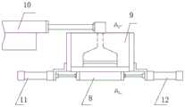
图3为立体丝垫机头模板交叉网格化往复运动装置图;Fig. 3 is the diagram of the cross-grid reciprocating motion device of the three-dimensional silk cushion head template;
图4为组合模板运动结构示意图;Fig. 4 is the schematic diagram of combined template motion structure;
图5为交叉网格在空中的重叠形态图;Fig. 5 is an overlapping form diagram of the intersecting grid in the air;
图6为本发明组合摆动奇偶模板示意图2。Fig. 6 is a schematic diagram 2 of the combined wobble parity template of the present invention.
其中,1、1排单模板,2、2排单模板,3、3排单模板,4、4排单模板,5、5排单模板,6、奇数模板,7、偶数模板,8、组合摆动奇偶模板,9、机头,10、挤出机,11、左侧摆动装置,12、右侧摆动装置,13、成型辊,14、一体固定模板、15、集料导槽、16、丝束出孔,17、流道,18、分配板,19、底部沟槽连接件。Among them, 1, 1 row template, 2, 2 row template, 3, 3 row template, 4, 4 row template, 5, 5 row template, 6, odd template, 7, even template, 8, combination Swing parity template, 9, head, 10, extruder, 11, left swing device, 12, right swing device, 13, forming roller, 14, integral fixed template, 15, material collection guide groove, 16, wire Beam exit hole, 17, flow channel, 18, distribution plate, 19, bottom groove connector.
具体实施方式Detailed ways
下面通过具体实施例详述本发明,但不限制本发明的保护范围。如无特殊说明,本发明所采用的实验方法均为常规方法,所用实验器材、材料、试剂等均可从商业途径获得。The present invention is described in detail below through specific examples, but the protection scope of the present invention is not limited. Unless otherwise specified, the experimental methods used in the present invention are conventional methods, and the experimental equipment, materials, reagents, etc. used can be obtained from commercial sources.
实施例1Example 1
如图1所示,目前市场现有技术使用的模板为一体固定模板14,不可移动;本发明所采用的模板为组合分体移动式,为组合摆动奇偶模板8,如图2所示。As shown in Figure 1, the formwork used in the prior art in the market is integrated
机头9通过流道与挤出机10固定连接,机头9下端连接分配板18,分配板18下的模板为分体组合式,机头9两侧分别固定左侧摆动装置11与右侧摆动装置12,两个摆动装置分别单独带动模板沿机头9底部沟槽进行左右运动,底部沟槽与机头9机械密封。The
所述模板为组合摆动奇偶模板8,组合摆动奇偶模板8设有2-12排单模板,其中奇数模板6呈梳状连接,偶数模板7呈梳状连接,每排单模板的排距为均等或者不均等。每排单模板内部设有流道17,与流道17垂直方向设有集料导槽15,集料导槽15设有若干个丝束出孔16,每个丝束出孔16之间的距离为相等或不相等。The template is a combined
所述左侧摆动装置11与右侧摆动装置12可以分别是油缸、气缸、机械曲柄结构中的一种,改变驱动行程可改变制品交错网格的角度和形状。The left
现有技术一体固定模板14挤出的丝束为垂直向下,不能形成交叉网格化形式;本发明实施例1组合摆动奇偶模板8以5排为例说明,组合摆动奇偶模板8由5组相互独立的模板组成,1,3,5排由独立油缸驱动向左移动,2,4排由另一独立油缸驱动向右移动,1-5排单模板在移动的过程中挤出丝束,形成交叉网格状丝垫。The tow extruded by the integrated
实施例2Example 2
塑料原料经过挤出机10塑化,从总流道进入机头9,经过组合摆动奇偶模板8各个单模板中的流道17,流道17中的原料流入集料导槽15后进行暂时储存,后通过丝束出孔16均匀挤出丝束,挤出过程中,组合摆动奇偶模板8分别按奇数排、偶数排有规律左右摆动,使丝束形成有规律的菱形网格状,然后落到转动的成型辊13上,经冷却固化形成立体丝垫。The plastic raw material is plasticized by the
沿机头9左右方向排列的每排丝束,均由独立的1排单模板、2排单模板、3排单模板、4排单模板与5排单模板在移动过程中排料,即所有的奇数排由奇数模板6排出,所有的偶数排由偶数模板7排出,奇数模板6和偶数模板7同时反方向移动。Each row of tows arranged along the left and right directions of the
当奇数排丝束通过奇数模板6向左侧移动时,该排丝束运行轨迹向左上方前倾。与此同时,当偶数排丝束通过偶数模板7向右侧移动时,该排丝束运行轨迹向右上方前倾。奇偶排丝束组合重叠在空中的形状为交叉网格化外形,当落入旋转的成型辊13上,即可将交叉网格外形结点固化成型,如图5所示。When the odd-numbered tows moved to the left through the odd-numbered
实施例3Example 3
与实施例1不同的是,分配板18设有底部沟槽连接件19,所述组合摆动奇偶模板8通过底部沟槽连接件19与分配板18连接。The difference from
实施例4Example 4
本发明产品使用的原料为尼龙或者PP,原料通过挤出机10塑化将熔融状态的原料通过流道送入机头9,再通过组合摆动奇偶模板8,使丝束呈规律交叉网状落入旋转的成型辊13固化成型。The raw material used in the product of the present invention is nylon or PP, and the raw material is plasticized by the
以尼龙为例,本发明试验参数变化如下:Taking nylon as an example, the test parameters of the present invention change as follows:
原料:尼龙6,丝垫制品规格:450g/㎡Raw material:
采用现有技术常规的生产工艺制造的制品测试结果如下:The product test result that adopts prior art conventional production process to manufacture is as follows:
纵向力:1.60KN/m,横向力:0.83KN/m。Longitudinal force: 1.60KN/m, lateral force: 0.83KN/m.
采用本发明工艺制造的制品测试结果如下:The product test result that adopts process of the present invention to manufacture is as follows:
纵向力:1.72KN/m,横向力:1.76KN/m。Longitudinal force: 1.72KN/m, lateral force: 1.76KN/m.
注明:纵向力、横向力,均为拉伸断裂强度值。Note: Longitudinal force and transverse force are tensile breaking strength values.
由测试结果可知,采用本发明立体丝垫机头模板交叉网格化往复运动装置和方法制备的产品,其纵向强度基本没变化,横向强度则提高了一倍,使得产品的纵向及横向力基本均衡,解决了产品需要提升横向力使其达标,而必须增加产品重量的问题,节约了原料。As can be seen from the test results, the longitudinal strength of the product prepared by adopting the cross-grid reciprocating device and method of the three-dimensional wire cushion head template of the present invention does not change substantially, and the transverse strength is then doubled, so that the longitudinal and transverse forces of the product are basically the same. Equilibrium solves the problem that the product needs to increase the lateral force to make it meet the standard, and the product weight must be increased, saving raw materials.
以上所述实施方式仅为本发明的优选实施例,而并非本发明可行实施的全部实施例。对于本领域一般技术人员而言,在不背离本发明原理和精神的前提下对其所作出的任何显而易见的改动,都应当被认为包含在本发明的权利要求保护范围之内。The implementation manners described above are only preferred embodiments of the present invention, but not all feasible embodiments of the present invention. For those skilled in the art, any obvious changes made without departing from the principle and spirit of the present invention should be considered to be included in the protection scope of the claims of the present invention.
Claims (4)
Priority Applications (3)
| Application Number | Priority Date | Filing Date | Title |
|---|---|---|---|
| CN202110844597.8ACN113529282B (en) | 2021-07-26 | 2021-07-26 | Method and device for cross-grid reciprocating movement of three-dimensional silk cushion head template |
| PCT/CN2022/093338WO2023005363A1 (en) | 2021-07-26 | 2022-05-17 | Machine head and die cross-gridding reciprocating motion method and apparatus for three-dimensional filament mat ensional wire pad head template |
| US18/555,818US20240200246A1 (en) | 2021-07-26 | 2022-05-17 | Method for producing three-dimensinal filament mats by machine head and mould plate cross-gridding reciprocating motion and apparatus thereof |
Applications Claiming Priority (1)
| Application Number | Priority Date | Filing Date | Title |
|---|---|---|---|
| CN202110844597.8ACN113529282B (en) | 2021-07-26 | 2021-07-26 | Method and device for cross-grid reciprocating movement of three-dimensional silk cushion head template |
Publications (2)
| Publication Number | Publication Date |
|---|---|
| CN113529282A CN113529282A (en) | 2021-10-22 |
| CN113529282Btrue CN113529282B (en) | 2023-02-03 |
Family
ID=78089007
Family Applications (1)
| Application Number | Title | Priority Date | Filing Date |
|---|---|---|---|
| CN202110844597.8AActiveCN113529282B (en) | 2021-07-26 | 2021-07-26 | Method and device for cross-grid reciprocating movement of three-dimensional silk cushion head template |
Country Status (3)
| Country | Link |
|---|---|
| US (1) | US20240200246A1 (en) |
| CN (1) | CN113529282B (en) |
| WO (1) | WO2023005363A1 (en) |
Families Citing this family (1)
| Publication number | Priority date | Publication date | Assignee | Title |
|---|---|---|---|---|
| CN113529282B (en)* | 2021-07-26 | 2023-02-03 | 大连塑研塑料科技开发有限公司 | Method and device for cross-grid reciprocating movement of three-dimensional silk cushion head template |
Citations (10)
| Publication number | Priority date | Publication date | Assignee | Title |
|---|---|---|---|---|
| GB1042135A (en)* | 1962-06-07 | 1966-09-14 | Courtaulds Ltd | Reinforced thermoplastic material |
| CN101721854A (en)* | 2008-10-30 | 2010-06-09 | 打清股份有限公司 | Filter and exhaust device using the filter, and manufacture method and device of the filter |
| CN101780711A (en)* | 2010-02-23 | 2010-07-21 | 大连塑料研究所有限公司 | Equipment for continuously directly extruding honeycomb panel products |
| WO2013052371A2 (en)* | 2011-10-05 | 2013-04-11 | 3M Innovative Properties Company | Three-dimensional polymeric strand netting, dies, and methods of making the same |
| CN212560656U (en)* | 2020-05-20 | 2021-02-19 | 广东长牛电气科技有限公司 | Melt-blown fabric production device |
| CN112481835A (en)* | 2020-11-30 | 2021-03-12 | 厦门当盛新材料有限公司 | Production method of polyethylene film |
| CN112501785A (en)* | 2020-10-29 | 2021-03-16 | 广东协宏无纺布科技有限公司 | Production method and production equipment of high-strength non-woven fabric |
| CN113106634A (en)* | 2021-04-23 | 2021-07-13 | 大连塑研塑料科技开发有限公司 | Reciprocating bonding method and device for transverse wires in wire mat forming process |
| CN113103611A (en)* | 2021-04-13 | 2021-07-13 | 大连塑研塑料科技开发有限公司 | Multi-axis rotation, extrusion molding three-dimensional network structure product and molding method and equipment |
| CN113122936A (en)* | 2021-05-20 | 2021-07-16 | 特复拉(潍坊)新材料技术有限公司 | Spinning device for producing non-woven fabric and PP spun-bonded non-woven fabric, PET spun-bonded non-woven fabric and PE spun-bonded non-woven fabric produced by spinning device |
Family Cites Families (7)
| Publication number | Priority date | Publication date | Assignee | Title |
|---|---|---|---|---|
| JP2675865B2 (en)* | 1989-07-05 | 1997-11-12 | 旭硝子マテックス株式会社 | Continuous molding method for fiber-reinforced synthetic resin lattice |
| CA2239383C (en)* | 1995-12-22 | 2006-08-08 | Hoechst Celanese Corporation | Thermoplastic three-dimensional fiber network |
| AT404474B (en)* | 1997-03-21 | 1998-11-25 | Chemiefaser Lenzing Ag | NET-WIDE AREA FROM A POLYMER |
| JP3034513B1 (en)* | 1999-01-08 | 2000-04-17 | カール・フロイデンベルク | Spunbond nonwoven fabric manufacturing equipment |
| CN102191627B (en)* | 2010-03-16 | 2013-08-07 | 机械科学研究总院先进制造技术研究中心 | Composite material three dimensional weaving equipment |
| WO2014043603A1 (en)* | 2012-09-17 | 2014-03-20 | Cornell University | High performance nanofibers and mats |
| CN113529282B (en)* | 2021-07-26 | 2023-02-03 | 大连塑研塑料科技开发有限公司 | Method and device for cross-grid reciprocating movement of three-dimensional silk cushion head template |
- 2021
- 2021-07-26CNCN202110844597.8Apatent/CN113529282B/enactiveActive
- 2022
- 2022-05-17WOPCT/CN2022/093338patent/WO2023005363A1/ennot_activeCeased
- 2022-05-17USUS18/555,818patent/US20240200246A1/enactivePending
Patent Citations (10)
| Publication number | Priority date | Publication date | Assignee | Title |
|---|---|---|---|---|
| GB1042135A (en)* | 1962-06-07 | 1966-09-14 | Courtaulds Ltd | Reinforced thermoplastic material |
| CN101721854A (en)* | 2008-10-30 | 2010-06-09 | 打清股份有限公司 | Filter and exhaust device using the filter, and manufacture method and device of the filter |
| CN101780711A (en)* | 2010-02-23 | 2010-07-21 | 大连塑料研究所有限公司 | Equipment for continuously directly extruding honeycomb panel products |
| WO2013052371A2 (en)* | 2011-10-05 | 2013-04-11 | 3M Innovative Properties Company | Three-dimensional polymeric strand netting, dies, and methods of making the same |
| CN212560656U (en)* | 2020-05-20 | 2021-02-19 | 广东长牛电气科技有限公司 | Melt-blown fabric production device |
| CN112501785A (en)* | 2020-10-29 | 2021-03-16 | 广东协宏无纺布科技有限公司 | Production method and production equipment of high-strength non-woven fabric |
| CN112481835A (en)* | 2020-11-30 | 2021-03-12 | 厦门当盛新材料有限公司 | Production method of polyethylene film |
| CN113103611A (en)* | 2021-04-13 | 2021-07-13 | 大连塑研塑料科技开发有限公司 | Multi-axis rotation, extrusion molding three-dimensional network structure product and molding method and equipment |
| CN113106634A (en)* | 2021-04-23 | 2021-07-13 | 大连塑研塑料科技开发有限公司 | Reciprocating bonding method and device for transverse wires in wire mat forming process |
| CN113122936A (en)* | 2021-05-20 | 2021-07-16 | 特复拉(潍坊)新材料技术有限公司 | Spinning device for producing non-woven fabric and PP spun-bonded non-woven fabric, PET spun-bonded non-woven fabric and PE spun-bonded non-woven fabric produced by spinning device |
Also Published As
| Publication number | Publication date |
|---|---|
| WO2023005363A1 (en) | 2023-02-02 |
| CN113529282A (en) | 2021-10-22 |
| US20240200246A1 (en) | 2024-06-20 |
Similar Documents
| Publication | Publication Date | Title |
|---|---|---|
| CN113529282B (en) | Method and device for cross-grid reciprocating movement of three-dimensional silk cushion head template | |
| CN104985181A (en) | Laser scanning method for manufacturing three-dimensional object | |
| CN109501249B (en) | Variable-section open-pore grid supporting structure and generation method thereof | |
| CN1205267A (en) | Method and device for producing honeycombs for beekeeping | |
| CN202992619U (en) | Solid plate and extrusion die for manufacturing same | |
| CN113103611B (en) | Multi-shaft rotating and extrusion molding three-dimensional net-shaped structure product and molding method and equipment | |
| CN101138458B (en) | High elasticity netted plastic cushion, producing method and equipment thereof | |
| CN212445691U (en) | Even extrusion device of mud material | |
| CN103211438A (en) | Multifunctional high-elasticity plastic soft pad as well as continuous production process and continuous production device of pad | |
| CN111716753B (en) | Processing machine and forming processing method for PE pearl wool packaging structure | |
| CN113106634B (en) | Method and device for reciprocating bonding of transverse filaments in filament mat forming process | |
| CN214263293U (en) | Extension forming device for continuously extruding large-diameter high-strength copper-magnesium alloy bars | |
| CN213835799U (en) | Double-row hole melt-blown plate | |
| CN112676365B (en) | Equipment and method for continuously extruding large-diameter high-strength copper-magnesium alloy bars | |
| CN203244157U (en) | Multifunctional high-elasticity plastic soft cushion and continuous production device thereof | |
| CN105216267A (en) | A kind of broadsheet efficient uniform extruder head and extrusion method | |
| CN210500771U (en) | Pneumatic sweeping device for skip of block forming machine | |
| CN201080007Y (en) | Plastic corrugated pipe forming device | |
| CN206464354U (en) | A kind of high surface requirements section bar mould | |
| AU731107B2 (en) | Anisotropic mat of continuous glass yarns and process of manufacture | |
| CN212453656U (en) | Vibrating template of slip form forming machine | |
| CN217258240U (en) | Mould distributor with multiple runners | |
| CN206887272U (en) | Spinneret die for micro Denier PET | |
| CN222060940U (en) | A grille automation device and a sliding plate pressing mechanism thereof | |
| JPS6044418B2 (en) | Matuto manufacturing method |
Legal Events
| Date | Code | Title | Description |
|---|---|---|---|
| PB01 | Publication | ||
| PB01 | Publication | ||
| SE01 | Entry into force of request for substantive examination | ||
| SE01 | Entry into force of request for substantive examination | ||
| GR01 | Patent grant | ||
| GR01 | Patent grant | ||
| TR01 | Transfer of patent right | Effective date of registration:20241127 Address after:No. 18 Fenghe South Road, Tieshan Street, Lushunkou District, Dalian City, Liaoning Province 116045 Patentee after:DALIAN PLASTICS RESEARCH INSTITUTE Co.,Ltd. Country or region after:China Address before:116033 No. 417, No. 1, Chuangxin Road, Lushunkou District, Dalian City, Liaoning Province Patentee before:DALIAN PLASTICS RESEARCH PLASTIC TECHNOLOGY DEVELOPMENT CO.,LTD. Country or region before:China | |
| TR01 | Transfer of patent right |