CN113507893B - Cartridge receiving jaw for surgical stapler and related manufacturing method using MIM - Google Patents
Cartridge receiving jaw for surgical stapler and related manufacturing method using MIMDownload PDFInfo
- Publication number
- CN113507893B CN113507893BCN201980093436.0ACN201980093436ACN113507893BCN 113507893 BCN113507893 BCN 113507893BCN 201980093436 ACN201980093436 ACN 201980093436ACN 113507893 BCN113507893 BCN 113507893B
- Authority
- CN
- China
- Prior art keywords
- elongate
- elongated
- lower jaw
- anvil
- recessed
- Prior art date
- Legal status (The legal status is an assumption and is not a legal conclusion. Google has not performed a legal analysis and makes no representation as to the accuracy of the status listed.)
- Active
Links
Images


Classifications
- A—HUMAN NECESSITIES
- A61—MEDICAL OR VETERINARY SCIENCE; HYGIENE
- A61B—DIAGNOSIS; SURGERY; IDENTIFICATION
- A61B17/00—Surgical instruments, devices or methods
- A61B17/068—Surgical staplers, e.g. containing multiple staples or clamps
- A61B17/072—Surgical staplers, e.g. containing multiple staples or clamps for applying a row of staples in a single action, e.g. the staples being applied simultaneously
- A61B17/07207—Surgical staplers, e.g. containing multiple staples or clamps for applying a row of staples in a single action, e.g. the staples being applied simultaneously the staples being applied sequentially
- B—PERFORMING OPERATIONS; TRANSPORTING
- B21—MECHANICAL METAL-WORKING WITHOUT ESSENTIALLY REMOVING MATERIAL; PUNCHING METAL
- B21K—MAKING FORGED OR PRESSED METAL PRODUCTS, e.g. HORSE-SHOES, RIVETS, BOLTS OR WHEELS
- B21K5/00—Making tools or tool parts, e.g. pliers
- B—PERFORMING OPERATIONS; TRANSPORTING
- B23—MACHINE TOOLS; METAL-WORKING NOT OTHERWISE PROVIDED FOR
- B23K—SOLDERING OR UNSOLDERING; WELDING; CLADDING OR PLATING BY SOLDERING OR WELDING; CUTTING BY APPLYING HEAT LOCALLY, e.g. FLAME CUTTING; WORKING BY LASER BEAM
- B23K9/00—Arc welding or cutting
- B23K9/02—Seam welding; Backing means; Inserts
- A—HUMAN NECESSITIES
- A61—MEDICAL OR VETERINARY SCIENCE; HYGIENE
- A61B—DIAGNOSIS; SURGERY; IDENTIFICATION
- A61B17/00—Surgical instruments, devices or methods
- A61B2017/00526—Methods of manufacturing
- A—HUMAN NECESSITIES
- A61—MEDICAL OR VETERINARY SCIENCE; HYGIENE
- A61B—DIAGNOSIS; SURGERY; IDENTIFICATION
- A61B17/00—Surgical instruments, devices or methods
- A61B17/068—Surgical staplers, e.g. containing multiple staples or clamps
- A61B17/072—Surgical staplers, e.g. containing multiple staples or clamps for applying a row of staples in a single action, e.g. the staples being applied simultaneously
- A61B2017/07214—Stapler heads
- A61B2017/07257—Stapler heads characterised by its anvil
- A61B2017/07264—Stapler heads characterised by its anvil characterised by its staple forming cavities, e.g. geometry or material
- A—HUMAN NECESSITIES
- A61—MEDICAL OR VETERINARY SCIENCE; HYGIENE
- A61B—DIAGNOSIS; SURGERY; IDENTIFICATION
- A61B17/00—Surgical instruments, devices or methods
- A61B17/068—Surgical staplers, e.g. containing multiple staples or clamps
- A61B17/072—Surgical staplers, e.g. containing multiple staples or clamps for applying a row of staples in a single action, e.g. the staples being applied simultaneously
- A61B2017/07214—Stapler heads
- A61B2017/07271—Stapler heads characterised by its cartridge
- A—HUMAN NECESSITIES
- A61—MEDICAL OR VETERINARY SCIENCE; HYGIENE
- A61B—DIAGNOSIS; SURGERY; IDENTIFICATION
- A61B17/00—Surgical instruments, devices or methods
- A61B17/068—Surgical staplers, e.g. containing multiple staples or clamps
- A61B17/072—Surgical staplers, e.g. containing multiple staples or clamps for applying a row of staples in a single action, e.g. the staples being applied simultaneously
- A61B2017/07214—Stapler heads
- A61B2017/07278—Stapler heads characterised by its sled or its staple holder
- A—HUMAN NECESSITIES
- A61—MEDICAL OR VETERINARY SCIENCE; HYGIENE
- A61B—DIAGNOSIS; SURGERY; IDENTIFICATION
- A61B17/00—Surgical instruments, devices or methods
- A61B17/068—Surgical staplers, e.g. containing multiple staples or clamps
- A61B17/072—Surgical staplers, e.g. containing multiple staples or clamps for applying a row of staples in a single action, e.g. the staples being applied simultaneously
- A61B2017/07214—Stapler heads
- A61B2017/07285—Stapler heads characterised by its cutter
- A—HUMAN NECESSITIES
- A61—MEDICAL OR VETERINARY SCIENCE; HYGIENE
- A61B—DIAGNOSIS; SURGERY; IDENTIFICATION
- A61B17/00—Surgical instruments, devices or methods
- A61B17/28—Surgical forceps
- A61B17/29—Forceps for use in minimally invasive surgery
- A61B2017/2926—Details of heads or jaws
- A61B2017/2927—Details of heads or jaws the angular position of the head being adjustable with respect to the shaft
- A—HUMAN NECESSITIES
- A61—MEDICAL OR VETERINARY SCIENCE; HYGIENE
- A61B—DIAGNOSIS; SURGERY; IDENTIFICATION
- A61B17/00—Surgical instruments, devices or methods
- A61B17/28—Surgical forceps
- A61B17/29—Forceps for use in minimally invasive surgery
- A61B2017/2926—Details of heads or jaws
- A61B2017/2932—Transmission of forces to jaw members
- A61B2017/2933—Transmission of forces to jaw members camming or guiding means
- A61B2017/2936—Pins in guiding slots
- B—PERFORMING OPERATIONS; TRANSPORTING
- B33—ADDITIVE MANUFACTURING TECHNOLOGY
- B33Y—ADDITIVE MANUFACTURING, i.e. MANUFACTURING OF THREE-DIMENSIONAL [3-D] OBJECTS BY ADDITIVE DEPOSITION, ADDITIVE AGGLOMERATION OR ADDITIVE LAYERING, e.g. BY 3-D PRINTING, STEREOLITHOGRAPHY OR SELECTIVE LASER SINTERING
- B33Y10/00—Processes of additive manufacturing
Landscapes
- Health & Medical Sciences (AREA)
- Engineering & Computer Science (AREA)
- Surgery (AREA)
- Life Sciences & Earth Sciences (AREA)
- Mechanical Engineering (AREA)
- Molecular Biology (AREA)
- Heart & Thoracic Surgery (AREA)
- Medical Informatics (AREA)
- Biomedical Technology (AREA)
- Animal Behavior & Ethology (AREA)
- General Health & Medical Sciences (AREA)
- Public Health (AREA)
- Veterinary Medicine (AREA)
- Nuclear Medicine, Radiotherapy & Molecular Imaging (AREA)
- Physics & Mathematics (AREA)
- Plasma & Fusion (AREA)
- Surgical Instruments (AREA)
Abstract
Translated fromChinese
Description
Translated fromChinese背景技术Background technique
内窥镜式外科器械可包括位于端部执行器和由临床医生操纵的柄部部分之间的轴。此轴可使得能够通过套管针插入到期望的深度并围绕轴的纵向轴线旋转,由此有利于将端部执行器定位在患者体内。还可通过包括一个或多个关节运动接头或特征部而进一步有利于定位该端部执行器,使得端部执行器能够选择性地进行关节运动或者以其他方式相对于轴的纵向轴线偏转。Endoscopic surgical instruments may include a shaft positioned between an end effector and a handle portion manipulated by a clinician. This shaft may enable insertion through the trocar to a desired depth and rotation about the longitudinal axis of the shaft, thereby facilitating positioning of the end effector within the patient. Positioning the end effector may also be further facilitated by including one or more articulation joints or features such that the end effector can be selectively articulated or otherwise deflected relative to the longitudinal axis of the shaft.
内窥镜式外科器械的示例包括外科缝合器。一些此类缝合器能够操作以夹紧组织层,切穿夹持的组织层,并且将钉驱动穿过组织层,以在组织层的切断端部附近将切断的组织层基本上密封在一起。仅示例性外科缝合器在以下美国专利中有所公开:2008年6月3日公布的名称为“Articulating Surgical Stapling Instrument Incorporating a Two-Piece E-Beam Firing Mechanism”的美国专利7,380,696;2013年4月2日公布的名称为“Surgical Stapling Instrument with An Articulatable End Effector”的美国专利8,408,439;和2013年6月4日公布的名称为“Motor-Driven Surgical Cutting Instrumentwith Electric Actuator Directional Control Assembly”的美国专利8,453,914。上面所引用的美国专利和美国专利公布中的每一个的公开内容以引用方式并入本文。Examples of endoscopic surgical instruments include surgical staplers. Some such staplers are operable to grip tissue layers, cut through the gripped tissue layers, and drive staples through the tissue layers to substantially seal the severed tissue layers together near their severed ends. Only exemplary surgical staplers are disclosed in the following U.S. Patents: U.S. Patent 7,380,696, issued June 3, 2008, entitled "Articulating Surgical Stapling Instrument Incorporating a Two-Piece E-Beam Firing Mechanism"; April 2013 U.S. Patent 8,408,439 titled "Surgical Stapling Instrument with An Articulatable End Effector" published on the 2nd; and U.S. Patent 8,453,914 titled "Motor-Driven Surgical Cutting Instrument with Electric Actuator Directional Control Assembly" published on June 4, 2013. The disclosures of each of the above-cited US Patents and US Patent Publications are incorporated herein by reference.
外科缝合器也可用于开腹手术和/或其他非内窥镜式手术。仅以举例的方式,在胸廓外科手术中,外科缝合器可通过胸廓切开术插入,并由此位于患者肋骨之间以到达一个或多个器官,该胸廓外科手术不使用套管针作为缝合器的导管。例如,在从胸腔中取出器官之前,可通过缝合器来切断并闭合通向器官的血管。当然,外科缝合器可用于各种其他情况和手术中。Surgical staplers may also be used in laparotomy and/or other non-endoscopic procedures. By way of example only, in thoracic surgery where a trocar is not used as a suture, a surgical stapler may be inserted through a thoracotomy and thereby positioned between a patient's ribs to access one or more organs device conduit. For example, a stapler may be used to cut and close blood vessels leading to the organ before removing the organ from the chest cavity. Of course, surgical staplers can be used in a variety of other situations and procedures.
虽然已制造和使用各种外科缝合器械和相关联的部件,但据信在本发明人之前还无人制造或使用在所附权利要求中所描述的发明。While various surgical stapling instruments and associated components have been made and used, it is believed that no one prior to the present inventor has made or used the invention described in the appended claims.
附图说明Description of drawings
并入本说明书中并构成本说明书的一部分的附图示出了本发明的实施方案,并且与上面给出的本发明的一般描述以及下面给出的实施方案的详细描述一起用于解释本发明的原理。The accompanying drawings, which are incorporated in and constitute a part of this specification, illustrate embodiments of the invention and together with the general description of the invention given above and the detailed description of the embodiments given below serve to explain the invention principle.
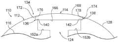
图1示出了第一示例性外科缝合器械的透视图;Figure 1 shows a perspective view of a first exemplary surgical stapling instrument;
图2示出了具有第一示例性端部执行器的图1的器械的侧视图;Figure 2 shows a side view of the instrument of Figure 1 with a first exemplary end effector;
图3示出了处于打开构型的图1的器械的端部执行器的透视图;Figure 3 shows a perspective view of the end effector of the instrument of Figure 1 in an open configuration;
图4A示出了图3的端部执行器沿图3的线4-4截取的侧剖视图,其中击发梁处于近侧位置;4A shows a side cross-sectional view of the end effector of FIG. 3 taken along line 4-4 of FIG. 3 with the firing beam in a proximal position;
图4B示出了图3的端部执行器沿图3的线4-4截取的侧剖视图,其中击发梁处于远侧位置;4B shows a side cross-sectional view of the end effector of FIG. 3 taken along line 4-4 of FIG. 3 with the firing beam in the distal position;
图5示出了图3的端部执行器沿图3的线5-5截取的端部剖视图;Figure 5 shows an end cross-sectional view of the end effector of Figure 3 taken along line 5-5 of Figure 3;
图6示出了图3的端部执行器的分解透视图;Figure 6 shows an exploded perspective view of the end effector of Figure 3;
图7示出了可结合到图1的器械中的第一示例性另选下钳口的右下透视图;Figure 7 shows a bottom right perspective view of a first exemplary alternative lower jaw that may be incorporated into the instrument of Figure 1;
图8示出了图7的下钳口的右下分解透视图,其中下钳口主体和细长盖为分开的;Figure 8 shows a bottom right exploded perspective view of the lower jaw of Figure 7 with the lower jaw body and elongated cover separated;
图9示出了图7的下钳口主体的底视图;Figure 9 shows a bottom view of the lower jaw body of Figure 7;
图10示出了图7的下钳口主体的顶视图;Figure 10 shows a top view of the lower jaw body of Figure 7;
图11示出了图7的下钳口主体的左侧视图;Figure 11 shows a left side view of the lower jaw body of Figure 7;
图12示出了图8的下钳口主体的远侧对准特征部的放大透视图;12 shows an enlarged perspective view of the distal alignment feature of the lower jaw body of FIG. 8;
图13示出了图8的下钳口主体的近侧对准特征部的放大透视图;13 shows an enlarged perspective view of the proximal alignment feature of the lower jaw body of FIG. 8;
图14示出了图7的下钳口和细长盖沿图7的线14-14截取的剖视图;Figure 14 shows a cross-sectional view of the lower jaw and elongated cover of Figure 7 taken along line 14-14 of Figure 7;
图14A示出了图14的下钳口主体和细长盖的放大剖视图;Figure 14A shows an enlarged cross-sectional view of the lower jaw body and elongated cover of Figure 14;
图15示出了可结合到图1的器械中的第二示例性另选下钳口的左侧透视图;Figure 15 shows a left side perspective view of a second exemplary alternative lower jaw that may be incorporated into the instrument of Figure 1;
图16示出了图15的下钳口的左侧分解透视图,该下钳口包括与细长盖分开的下钳口主体;Figure 16 shows a left side exploded perspective view of the lower jaw of Figure 15 including a lower jaw body separated from an elongated cover;
图17A示出了在成形之后但在被机加工之前的图16的下钳口主体的示意性剖面图;Figure 17A shows a schematic cross-sectional view of the lower jaw body of Figure 16 after forming but before being machined;
图17B示出了在被部分机加工之后但在被弯曲之前的图17A的下钳口主体的示意性剖面图;Figure 17B shows a schematic cross-sectional view of the lower jaw body of Figure 17A after being partially machined but before being bent;
图17C示出了在被机加工和弯曲之后的图17B的下钳口主体的示意性剖面图;Figure 17C shows a schematic cross-sectional view of the lower jaw body of Figure 17B after being machined and bent;
图18示出了图7的下钳口的示例性制造方法;Figure 18 shows an exemplary method of manufacturing the lower jaw of Figure 7;
图19示出了可结合到图1的器械中的第一示例性另选砧座的右上分解透视图;Figure 19 shows an upper right exploded perspective view of a first exemplary alternative anvil that may be incorporated into the instrument of Figure 1;
图20示出了图19的砧座的砧座主体的左下透视图;Figure 20 shows a lower left perspective view of the anvil body of the anvil of Figure 19;
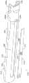
图21示出了在被机加工之前的图20的砧座主体的左下透视图;Figure 21 shows a lower left perspective view of the anvil body of Figure 20 before being machined;
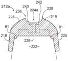
图22示出了图20的示意性左下剖面透视图,其示出了机加工部分;Figure 22 shows a schematic lower left cutaway perspective view of Figure 20 showing machined parts;
图23A示出了在成形之后但在被机加工之前的图20的砧座主体的示意性剖面图;Figure 23A shows a schematic cross-sectional view of the anvil body of Figure 20 after forming but before being machined;
图23B示出了在被机加工之后的图23A的砧座主体的示意性剖面图;Figure 23B shows a schematic cross-sectional view of the anvil body of Figure 23A after being machined;
图24A示出了图23B的砧座主体和图19的细长盖的示意性剖面图;Figure 24A shows a schematic cross-sectional view of the anvil body of Figure 23B and the elongated cover of Figure 19;
图24B示出了图23B的砧座和示例性细长盖的示意性剖面图;Figure 24B shows a schematic cross-sectional view of the anvil and exemplary elongated cap of Figure 23B;
图25A示出了图24A的砧座主体和细长盖之间的侧向间隙的放大部分的示意性剖面图;Figure 25A shows a schematic cross-sectional view of an enlarged portion of the lateral gap between the anvil body and the elongated cover of Figure 24A;
图25B示出了图24B的砧座主体和细长盖之间的配合的放大部分的示意性剖面图;Figure 25B shows a schematic cross-sectional view of an enlarged portion of the fit between the anvil body and the elongated cover of Figure 24B;
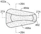
图26A示出了在被压印或电化学加工之前的图20的钉成形凹坑;Figure 26A shows the staple forming dimples of Figure 20 prior to being embossed or electrochemically machined;
图26B示出了在被压印或电化学加工之后的图20的钉成形凹坑;Figure 26B shows the staple forming dimples of Figure 20 after being embossed or electrochemically machined;
图27A示出了图26A的钉成形凹坑的中心部分沿图26A的线27A-27A截取的示意性剖面图;Figure 27A shows a schematic cross-sectional view of the central portion of the staple forming pocket of Figure 26A taken along
图27B示出了图26B的钉成形凹坑的中心部分沿图26B的线27B-27B截取的示意性剖面图;Figure 27B shows a schematic cross-sectional view of the central portion of the staple forming pocket of Figure 26B taken along
图28A示出了图26A的钉成形凹坑的一部分沿图26A的线28A-28A截取的示意性剖面图;Figure 28A shows a schematic cross-sectional view of a portion of the staple forming pocket of Figure 26A taken along
图28B示出了图26B的钉成形凹坑的一部分沿图26B的线28B-28B截取的示意性剖面图;Figure 28B shows a schematic cross-sectional view of a portion of the staple forming pocket of Figure 26B taken along
图29示出了在被压印或电化学加工之后的图26B的多个单独的钉成形凹坑;Figure 29 shows the individual staple forming pockets of Figure 26B after being embossed or electrochemically machined;
图30示出了可结合到图1的器械中的第二示例性另选砧座的右上分解透视图;并且Figure 30 shows an upper right exploded perspective view of a second exemplary alternative anvil that may be incorporated into the instrument of Figure 1; and
图31示出了图19的砧座的示例性制造方法。FIG. 31 illustrates an exemplary method of manufacturing the anvil of FIG. 19 .
附图并非旨在以任何方式进行限制,并且可以设想本发明的各种实施方案可以多种其他方式来执行,包括那些未必在附图中示出的方式。并入本说明书中并构成其一部分的附图示出了本发明的若干方面,并与说明书一起用于解释本发明的原理;然而,应当理解,本发明并不限于所示出的明确布置方式。The drawings are not intended to be limiting in any way, and it is contemplated that various embodiments of the invention may be carried out in numerous other ways, including those not necessarily shown in the drawings. The accompanying drawings, which are incorporated in and constitute a part of this specification, illustrate several aspects of the invention and together with the description serve to explain the principles of the invention; it is to be understood, however, that the invention is not limited to the precise arrangements shown. .
具体实施方式Detailed ways
下面对本技术的某些示例的说明不应用于限制本技术的范围。从下面的描述而言,本技术的其他示例、特征、方面、实施方案和优点对于本领域的技术人员而言将变得显而易见,下面的描述以举例的方式进行,这是为实现本技术所设想的最好的方式中的一种方式。正如将意识到的,本文所述的技术能够具有其他不同的和明显的方面,所有这些方面均不脱离本技术。因此,附图和说明应被视为实质上是例示性的而非限制性的。The following description of certain examples of the technology should not be used to limit the scope of the technology. Other examples, features, aspects, embodiments, and advantages of the present technology will become apparent to those skilled in the art from the following description, which is done by way of example and is intended to enable the present technology One of the best ways conceived. As will be realized, the technology described herein is capable of other different and obvious aspects, all without departing from the technology. Accordingly, the drawings and descriptions are to be regarded as illustrative in nature and not restrictive.
另外应当理解,本文所述的教导内容、表达方式、实施方案、示例等中的任何一者或多者可与本文所述的其它教导内容、表达方式、实施方案、示例等中的任何一者或多者相结合。因此,下述教导内容、表达方式、实施方案、实施例等不应视为彼此孤立。参考本文的教导内容,本文的教导内容可进行组合的各种合适方式对于本领域的普通技术人员而言将显而易见。此类修改和变型旨在包括在权利要求书的范围内。It should also be understood that any one or more of the teachings, expressions, embodiments, examples, etc. described herein may be combined with any of the other teachings, expressions, embodiments, examples, etc. described herein. or a combination of them. Accordingly, the following teachings, expressions, embodiments, examples, etc. should not be considered in isolation from each other. Various suitable ways in which the teachings herein may be combined will be apparent to those of ordinary skill in the art in view of the teachings herein. Such modifications and variations are intended to be included within the scope of the claims.
为公开内容的清楚起见,术语“近侧”和“远侧”在本文中相对于外科器械的人或机器人操作者而定义。术语“近侧”是指更靠近外科器械的人或机器人操作者并且更远离外科器械的外科端部执行器的元件位置。术语“远侧”是指更靠近外科器械的外科端部执行器并且更远离外科器械的人或机器人操作者的元件位置。此外,术语“上”、“下”、“侧向”、“横向”、“底部”、“顶部”为相对术语,以向下面提供的图描述提供附加清晰度。因此,术语“上”、“下”、“侧向”、“横向”、“底部”“顶部”不旨在不必要地限制本文所述的本发明。For clarity of disclosure, the terms "proximal" and "distal" are defined herein with respect to a human or robotic operator of the surgical instrument. The term "proximal" refers to the location of elements of the surgical end effector that are closer to the human or robotic operator of the surgical instrument and farther away from the surgical instrument. The term "distal" refers to an element location that is closer to the surgical end effector of the surgical instrument and farther from the human or robotic operator of the surgical instrument. Furthermore, the terms "upper", "lower", "lateral", "transverse", "bottom", "top" are relative terms to provide additional clarity to the description of the figures provided below. Thus, the terms "upper", "lower", "lateral", "transverse", "bottom" and "top" are not intended to unnecessarily limit the invention described herein.
此外,术语“第一”和“第二”在本文中用于区分外科器械的一个或多个部分。例如,第一组件和第二组件可另选地且分别被描述为第二组件和第一组件。术语“第一”和“第二”以及其他数字名称仅为此类术语的示例,并非旨在不必要地限制本文所述的本发明。Additionally, the terms "first" and "second" are used herein to distinguish one or more portions of a surgical instrument. For example, a first component and a second component may alternatively and respectively be described as a second component and a first component. The terms "first" and "second" and other numerical designations are examples of such terms only and are not intended to unnecessarily limit the invention described herein.
I.具有第一示例性端部执行器的第一示例性外科器械I. A first exemplary surgical instrument with a first exemplary end effector
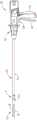
图1至图6示出了第一示例性外科缝合和切割器械(10),其尺寸被设定成通过套管针套管或切口(例如,胸廓切开术等)插入患者的手术部位以执行外科手术。本示例的器械(10)包括连接到轴(22)的主体(被示为柄部部分(20)),该轴在远侧终止于关节运动接头(11)中,该关节运动接头进一步与第一示例性端部执行器(12)联接。轴(22)可根据以下美国专利的教导内容中的至少一些教导内容进行构造:2017年10月24日公布的名称为“Surgical Instrument with Multi-Diameter Shaft”的美国专利9,795,379,该专利的公开内容以引用方式并入本文。Figures 1-6 illustrate a first exemplary surgical stapling and cutting instrument (10) sized to be inserted into a patient's surgical site through a trocar cannula or incision (e.g., thoracotomy, etc.) to Perform surgery. The instrument (10) of the present example includes a body (shown as handle portion (20)) connected to a shaft (22) that terminates distally in an articulation joint (11) that is further connected to a second An exemplary end effector (12) is coupled. Shaft (22) may be constructed in accordance with at least some of the teachings of the following U.S. Patent: U.S. Patent 9,795,379, issued October 24, 2017, entitled "Surgical Instrument with Multi-Diameter Shaft," the disclosure of which Incorporated herein by reference.
一旦关节运动接头(11)和端部执行器(12)穿过套管针的插管通道插入,关节运动接头(11)就可通过关节运动控件(13)进行远程关节运动,如图1中以虚像所描绘的,使得端部执行器(12)可从轴(22)的纵向轴线(LA)以所需角度(α)偏转。关节运动接头(11)和/或关节运动控件(13)可根据以下美国专利的教导内容中的至少一些教导内容进行构造并能够操作:2015年11月17日提交的名称为“Surgical Instrument End Effector ArticulationDrive with Pinion and Opposing Racks”的美国专利9,186,142,该专利的公开内容以引用方式并入本文;以及/或者美国专利9,795,379,该专利的公开内容以引用方式并入本文。Once the articulation joint (11) and end effector (12) are inserted through the cannula channel of the trocar, the articulation joint (11) can be remotely articulated via the articulation control (13), as shown in Figure 1 Depicted in phantom, the end effector (12) is deflectable at a desired angle (α) from the longitudinal axis (LA) of the shaft (22). The articulation joint (11) and/or articulation control (13) may be constructed and operable in accordance with at least some of the teachings of the following U.S. Patent: "Surgical Instrument End Effector" filed on November 17, 2015 Articulation Drive with Pinion and Opposing Racks", U.S. Patent 9,186,142, the disclosure of which is incorporated herein by reference; and/or U.S. Patent 9,795,379, the disclosure of which is incorporated herein by reference.
本示例的端部执行器(12)包括下钳口(16)和可枢转砧座(18)。下钳口(16)可根据以下美国专利的教导内容中的至少一些教导内容进行构造:2017年11月7日公布的名称为“Installation Features for Surgical Instrument End Effector Cartridge”的美国专利9,808,248,该专利的公开内容以引用方式并入本文。砧座(18)可以根据以下美国专利的教导内容中的至少一些教导内容进行构造:2016年12月13日公布的名称为“IntegratedTissue Positioning and Jaw Alignment Features for Surgical Stapler”的美国专利9,517,065,该专利的公开内容以引用方式并入本文;2017年12月12日公布的名称为“JawClosure Feature for End Effector of Surgical Instrument”的美国专利9,839,421,该专利的公开内容以引用方式并入本文;以及/或者2014年8月28日公布的名称为“StapleForming Features for Surgical Stapling Instrument”的美国公布2014/0239037,该专利的公开内容以引用方式并入本文。The end effector (12) of the present example includes a lower jaw (16) and a pivotable anvil (18). The lower jaw (16) may be constructed in accordance with at least some of the teachings of the following U.S. Patent: U.S. Patent 9,808,248, issued November 7, 2017, entitled "Installation Features for Surgical Instrument End Effector Cartridge," which The disclosure of is incorporated herein by reference. The anvil (18) may be constructed in accordance with at least some of the teachings of the following U.S. Patent: U.S. Patent 9,517,065, issued December 13, 2016, entitled "Integrated Tissue Positioning and Jaw Alignment Features for Surgical Stapler," which U.S. Patent 9,839,421, issued December 12, 2017, entitled "JawClosure Feature for End Effector of Surgical Instrument," the disclosure of which is incorporated herein by reference; and/or US Publication 2014/0239037, entitled "StapleForming Features for Surgical Stapling Instrument," published August 28, 2014, the disclosure of which is incorporated herein by reference.
柄部部分(20)包括手枪式握把(24)和闭合触发器(26)。闭合触发器(26)能够朝向手枪式握把(24)枢转,以使得砧座(18)朝向端部执行器(12)的下钳口(16)夹紧或闭合。砧座(18)的此类闭合是通过闭合管(32)和闭合环(33)提供的,这两者响应于闭合触发器(26)相对于手枪式握把(24)的枢转而相对于柄部部分(20)纵向地平移。闭合管(32)沿轴(22)的长度延伸;并且闭合环(33)定位在关节运动接头(11)的远侧。关节运动接头(11)能够操作以将纵向运动从闭合管(32)传送/传输到闭合环(33)。柄部部分(20)也包括击发触发器(28)(如图2所示)。细长构件(未示出)纵向延伸穿过轴(22),并响应于激发触发器(28)的致动,从柄部部分(20)向击发梁(14)传递纵向击发运动。击发梁(14)的这种远侧平移使得端部执行器(12)中夹紧的组织被缝合和切断,如下文将更详细地描述的。The handle portion (20) includes a pistol grip (24) and a closure trigger (26). A closure trigger (26) is pivotable toward the pistol grip (24) to cause the anvil (18) to clamp or close toward the lower jaw (16) of the end effector (12). Such closure of the anvil (18) is provided by a closure tube (32) and a closure ring (33), which oppose each other in response to the pivoting of the closure trigger (26) relative to the pistol grip (24). Translate longitudinally on the handle portion (20). A closed tube (32) extends along the length of the shaft (22); and a closed loop (33) is positioned distally of the articulation joint (11). The articulation joint (11) is operable to transmit/transmit longitudinal motion from the closed tube (32) to the closed loop (33). The handle portion (20) also includes a firing trigger (28) (shown in Figure 2). An elongated member (not shown) extends longitudinally through shaft (22) and transmits longitudinal firing motion from handle portion (20) to firing beam (14) in response to actuation of firing trigger (28). This distal translation of firing beam (14) causes tissue clamped in end effector (12) to be stapled and severed, as will be described in more detail below.
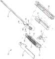
图3至图6描绘了采用电子束形式的击发梁(14)的端部执行器(12)。如最佳见于图4A至图4B,击发梁(14)包括横向取向的上部销(38)、击发梁盖(44)、横向取向的中部销(46)和处于远侧的切割刃(48)。上部销(38)被定位在砧座(18)的细长通道(42)内,并且能够在该细长通道内平移。击发梁盖(44)通过使击发梁(14)延伸穿过细长通道(45)(图4B所示)而可滑动地接合下钳口(16)的下表面,该细长通道是穿过下钳口(16)形成的。中部销(46)以滑动的方式接合下钳口(16)的顶表面,从而与击发梁盖(44)协作。击发梁(14)和/或相关联闭锁特征部可根据以下美国专利的教导内容中的至少一些教导内容进行构造并能够操作:2017年8月1日公布的名称为“Lockout Feature for Movable Cutting Member ofSurgical Instrument”的美国专利9,717,497,该专利的公开内容以引用方式并入本文。3-6 depict the end effector (12) employing a firing beam (14) in the form of an electron beam. As best seen in Figures 4A-4B, the firing beam (14) includes a transversely oriented upper pin (38), a firing beam cover (44), a transversely oriented middle pin (46), and a distally located cutting edge (48) . The upper pin (38) is positioned within the elongated channel (42) of the anvil (18) and is capable of translating within the elongated channel. The firing beam cover (44) slidably engages the lower surface of the lower jaw (16) by extending the firing beam (14) through the elongated channel (45) (shown in FIG. 4B ) that passes through the lower jaw. Jaws (16) are formed. The middle pin (46) slidably engages the top surface of the lower jaw (16), cooperating with the firing beam cover (44). The firing beam (14) and/or associated lockout feature may be constructed and operable in accordance with at least some of the teachings of the following U.S. Patent: Published August 1, 2017 entitled "Lockout Feature for Movable Cutting Member of Surgical Instrument", the disclosure of which is incorporated herein by reference.
图3示出本示例的朝近侧定位的击发梁(14)和枢转到打开位置的砧座(18),从而允许未耗尽的钉仓(37)可移除地安装到下钳口(16)的通道中。如最佳见于图5至图6,本示例的钉仓(37)包括仓体(70),该仓体呈现出上部平台(72)并与下部仓托盘(74)联接。如图3中最佳地示出,竖直狭槽(49)被形成为穿过钉仓(37)的一部分。同样如图3中最佳地示出,三排钉孔(51)被形成为在竖直狭槽(49)的一侧上穿过上部平台(72),另一组三排钉孔(51)被形成为在竖直狭槽(49)的另一侧上穿过上部平台(72)。如图4A至图6所示,楔形滑动件(41)和多个钉驱动器(43)被捕获在仓体(70)与托盘(74)之间,其中楔形滑动件(41)定位成接近钉驱动器(43)。楔形滑动件(41)能够在钉仓(37)内纵向地移动;而钉驱动器(43)能够在钉仓(37)内竖直地移动。钉(47)也被定位在仓体(70)内,位于对应的钉驱动器(43)上方。每个钉(47)在仓体(70)内被钉驱动器(43)竖直地驱动,以将钉(47)向外驱动穿过相关联的钉孔(51)。如图4A至图4B和图6中最佳地示出,楔形滑动件(41)存在倾斜凸轮表面,当楔形滑动件(41)朝远侧被驱动穿过钉仓(37)时,倾斜凸轮表面向上推压钉驱动器(43)。钉仓(37)可根据以下美国专利的教导内容中的至少一些教导内容进行构造并能够操作:美国专利9,517,065,该专利的公开内容以引用方式并入本文;以及/或者美国专利9,808,248,该专利的公开内容以引用方式并入本文。Figure 3 shows the proximally positioned firing beam (14) of the present example and the anvil (18) pivoted to an open position, allowing an unspent staple cartridge (37) to be removably mounted to the lower jaw (16) in the channel. As best seen in FIGS. 5-6 , the staple cartridge ( 37 ) of the present example includes a cartridge body ( 70 ) presenting an upper platform ( 72 ) coupled to a lower cartridge tray ( 74 ). As best shown in Figure 3, a vertical slot (49) is formed through a portion of the staple cartridge (37). Also best shown in Figure 3, three rows of nail holes (51) are formed through the upper platform (72) on one side of the vertical slot (49), another set of three rows of nail holes (51 ) is formed through the upper platform (72) on the other side of the vertical slot (49). As shown in Figures 4A-6, the wedge sled (41) and the plurality of staple drivers (43) are captured between the cartridge body (70) and the tray (74), with the wedge sled (41) positioned proximate to the staples. drive (43). The wedge sled (41) is movable longitudinally within the staple cartridge (37); and the staple driver (43) is movable vertically within the staple cartridge (37). Staples (47) are also positioned within cartridge body (70), above corresponding staple drivers (43). Each staple (47) is driven vertically within the cartridge body (70) by a staple driver (43) to drive the staples (47) outwardly through the associated staple hole (51). As best shown in FIGS. 4A-4B and FIG. 6 , wedge sled (41) presents an angled cam surface that when wedge sled (41) is driven distally through staple cartridge (37), the angled cam surface The surface pushes the staple driver (43) upward. Staple cartridge (37) may be constructed and operable in accordance with the teachings of at least some of the following U.S. Patents: U.S. Patent 9,517,065, the disclosure of which is incorporated herein by reference; and/or U.S. Patent 9,808,248, which The disclosure of is incorporated herein by reference.
在通过朝远侧推进闭合管(32)和闭合环(33)以使端部执行器(12)如图4A至图4B所示闭合的情况下,通过使上部销(38)进入砧座(18)的纵向通道(42),将击发梁(14)随后推进到与砧座(18)接合。推块(80)(图5所示)位于击发梁(14)的远侧端部处,并且当致动击发触发器(28)时当击发梁(14)朝远侧推进穿过钉仓(37)时推动楔形滑动件(41)。在此类击发期间,击发梁(14)的切割刃(48)进入钉仓(37)的竖直狭槽(49),从而切断夹持在钉仓(37)和砧座(18)之间的组织。如图4A至图4B所示,中间销(46)和推块(80)通过进入钉仓(37)内的竖直狭槽(49)中而一起致动钉仓(37),从而将楔形滑动件(41)驱动成与钉驱动器(43)发生向上顶起接触,这继而将钉(47)向外驱动穿过钉孔(51)并使钉与砧座(18)的内表面上的钉成形凹坑(53)(图3所示)形成接触。图4B示出了在完成切断和缝合组织之后完全朝远侧平移的击发梁(14)。从图4A至图4B中的视图中有意地省略了钉成形凹坑(53);但在图3中示出。在图5的视图中有意地省略了砧座(18)。在一些型式中,砧座(18)围绕由销(或类似的特征部)限定的轴线枢转,该销(或类似的特征部)在砧座(18)朝向下钳口(16)移动时,沿着细长狭槽或通道滑动。在此类型式中,枢转轴线沿着由狭槽和通道限定的路径平移,而砧座(18)同时围绕该轴线枢转。With the end effector (12) closed as shown in FIGS. 18), the firing beam (14) is then advanced into engagement with the anvil (18). A push block (80) (shown in FIG. 5 ) is located at the distal end of the firing beam (14) and when the firing trigger (28) is actuated the firing beam (14) is advanced distally through the staple cartridge ( 37) to push the wedge-shaped slider (41). During such a firing, the cutting edge (48) of the firing beam (14) enters the vertical slot (49) of the staple cartridge (37), thereby severing the staple clamped between the staple cartridge (37) and the anvil (18). organization. As shown in Figures 4A-4B, the center pin (46) and pusher block (80) together actuate the staple cartridge (37) by entering into the vertical slot (49) in the staple cartridge (37), thereby displacing the wedge. The slide (41) is driven into contact with the nail driver (43), which in turn drives the nail (47) outward through the nail hole (51) and makes the nail contact with the inner surface of the anvil (18). The staple forming pockets (53) (shown in Figure 3) make contact. Figure 4B shows the firing beam (14) fully translated distally after the tissue has been severed and stapled. The staple forming pocket ( 53 ) has been intentionally omitted from the view in FIGS. 4A-4B ; but is shown in FIG. 3 . The anvil ( 18 ) has been intentionally omitted from the view in FIG. 5 . In some versions, the anvil (18) pivots about an axis defined by a pin (or similar feature) that as the anvil (18) moves toward the lower jaw (16) , slides along an elongated slot or channel. In this type of version, the pivot axis translates along the path defined by the slot and channel while the anvil (18) simultaneously pivots about this axis.
器械(10)可另外根据本文引用的专利参考文献中的任一个参考文献的任何教导中的任一个教导内容进行构造并能够操作。可提供用于器械(10)的其它示例性修改将在下文中更详细地描述。下述教导内容并不限于本文引用的专利中所教导的器械(10)或装置。下述教导内容可易于应用到各种其它种类的器械,所述器械包括将不被归类为外科缝合器的器械。参考本文的教导内容,其中可应用下文教导内容的各种其它合适的装置和情况对本领域的普通技术人员将是显而易见的。Apparatus (10) may additionally be constructed and operable in accordance with any of the teachings of any of the patent references cited herein. Other exemplary modifications that may be provided for device (10) are described in more detail below. The following teachings are not limited to the apparatus (10) or devices taught in the patents cited herein. The following teachings are readily applicable to various other types of instruments, including instruments that would not be classified as surgical staplers. Various other suitable devices and situations in which the following teachings may be applied will be apparent to those of ordinary skill in the art in view of the teachings herein.
II.示例性下钳口、砧座及制造方法II. Exemplary Lower Jaws, Anvils, and Methods of Manufacturing
在一些常规制造工艺中,器械(10)的下钳口(16)或砧座(18)可由单个固体材料块(例如,金属)机加工而成。因此,下钳口(16)或砧座(18)的这种机加工可能为耗时的和昂贵的,这两种情况均为不期望的。本质上具有消耗性的常规机加工技术也可被认为是低效的,因为它们可在从单个固体材料块中移除的材料中产生废料。另外,在一些情况下,相当多的机加工可向下钳口(16)或砧座(18)中施加不期望的应力。因此,期望使用更快、更有效且更高性价比的工艺或工艺系统来制造下钳口(16),以进一步增强下钳口(16)或砧座(18)。另外,可能期望下钳口(16)或砧座(18)的特定部分和特征部具有严格的公差以有助于器械(10)的使用,而下钳口(16)或砧座(18)的其他特定部分和特征部可具有较宽松的公差,其中精确的尺寸不太重要。因此,期望制造示例性下钳口(110,210)和/或砧座(410,510),该下钳口和/或砧座为有效的、高性价比的和足够稳固的以与上述器械(10)的端部执行器(12)可互换地工作。In some conventional manufacturing processes, lower jaw (16) or anvil (18) of instrument (10) may be machined from a single solid block of material (eg, metal). Thus, such machining of the lower jaw (16) or anvil (18) can be time consuming and expensive, both of which are undesirable. Conventional machining techniques, which are consumable in nature, can also be considered inefficient because they can generate waste in the material removed from a single block of solid material. Additionally, in some cases, considerable machining can place undesired stresses in the lower jaw (16) or anvil (18). Therefore, it is desirable to further strengthen the lower jaw (16) or anvil (18) using a faster, more efficient and more cost-effective process or process system for manufacturing the lower jaw (16). Additionally, it may be desirable to have tight tolerances on certain portions and features of lower jaw (16) or anvil (18) to facilitate use of instrument (10) while lower jaw (16) or anvil (18) Other specific parts and features may have looser tolerances where exact dimensions are less critical. Accordingly, it is desirable to manufacture exemplary lower jaws (110, 210) and/or anvils (410, 510) that are efficient, cost-effective, and robust enough to mate with the end of the instrument (10) described above. The external actuators (12) work interchangeably.
如前所述,器械(10)包括主体(被示为柄部部分(20))、从主体延伸的轴(22)以及与轴(22)相连的端部执行器(12)。端部执行器(12)能够操作以压缩、缝合和切割组织。端部执行器(12)可包括可代替图1所示的下钳口(16)和/或砧座(18)使用的下钳口(110,210)和/或砧座(410,510)。换句话讲,并且如下文更详细地描述,下钳口(110,210)可代替器械(10)的下钳口(16)来使用,并且砧座(410,510)可代替器械(10)的砧座(18)来使用。另外,下钳口(110,210)可与砧座(410,510)一起使用。类似于其中砧座(18)相对于下钳口(16)枢转的器械(10)的操作,砧座(410,510)相对于下钳口(110,210)枢转。因此,砧座(410,510)和下钳口(210,310)可类似于由图1所示的砧座(18)和下钳口(16)执行的夹持来夹持组织。As previously mentioned, instrument (10) includes a body (shown as handle portion (20)), a shaft (22) extending from the body, and an end effector (12) coupled to shaft (22). End effector (12) is operable to compress, staple and cut tissue. End effector (12) may include lower jaws (110, 210) and/or anvils (410, 510) that may be used in place of lower jaws (16) and/or anvil (18) shown in FIG. 1 . In other words, and as described in more detail below, the lower jaws (110, 210) may be used in place of the lower jaws (16) of the instrument (10), and the anvils (410, 510) may be used in place of the anvils of the instrument (10) (18) to use. Additionally, lower jaws (110, 210) may be used with anvils (410, 510). Similar to the operation of instrument (10) in which anvil (18) pivots relative to lower jaw (16), anvil (410, 510) pivots relative to lower jaw (110, 210). Accordingly, the anvils ( 410 , 510 ) and lower jaws ( 210 , 310 ) can clamp tissue similar to the clamping performed by the anvil ( 18 ) and lower jaws ( 16 ) shown in FIG. 1 .
下钳口(110,210)和砧座(410,510)包括主体(例如,下钳口主体(112,212)和砧座主体(412,512))和细长盖(114,214,414,514,514a)。如将在下文更详细地讨论,细长盖(114,214,414,514,514a)被构造成能够例如通过焊接来固定到主体(例如,下钳口主体(112,212)或砧座主体(412,512))。类似于下钳口(16),下钳口(110,210)也被构造成能够接收钉仓(类似于图3所示的仓(37))。下面参考以下附图来描述下钳口(110,210)和砧座(410,510)的附加细节。The lower jaw (110, 210) and anvil (410, 510) include a body (eg, lower jaw body (112, 212) and anvil body (412, 512)) and an elongated cover (114, 214, 414, 514, 514a). As will be discussed in more detail below, the elongated cover (114, 214, 414, 514, 514a) is configured to be securable to a body (eg, lower jaw body (112, 212) or anvil body (412, 512)), such as by welding. Like lower jaw (16), lower jaw (110, 210) is also configured to receive a staple cartridge (similar to cartridge (37) shown in FIG. 3). Additional details of the lower jaws (110, 210) and anvils (410, 510) are described below with reference to the following figures.
A.第一示例性另选下钳口A. First Exemplary Alternative Lower Jaw
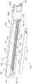
图7至图14A示出了第一示例性另选下钳口(110)。更具体地,图7示出了包括与细长盖(114)联接的下钳口主体(112)的下钳口(110)的右下透视图,而图8示出了与细长盖(114)分开一定距离的下钳口主体(112)的右下分解透视图。下钳口主体(112)包括置于相对的侧壁(118,120)之间的底壁(116),该相对的侧壁共同形成被构造成能够接收钉仓(例如,钉仓(37))的内腔(122)。下钳口主体(112)被示为大致U形的;然而,下钳口主体(112)可具有多种合适的形状。底壁(116)包括延伸穿过底壁(116)的内表面(126)和外表面(128)的细长通道(124)。如图7至图10所示,底壁(116)从近侧孔(130)纵向地延伸到远侧细长孔(132)。近侧孔(130)和远侧细长孔(132)完全延伸穿过底壁(116)的内表面(126)和外表面(128)。7-14A illustrate a first exemplary alternative lower jaw (110). More specifically, FIG. 7 shows a lower right perspective view of the lower jaw (110) comprising a lower jaw body (112) coupled with an elongated cover (114), while FIG. 114) Bottom right exploded perspective view of the lower jaw body (112) separated by a distance. Lower jaw body (112) includes a bottom wall (116) disposed between opposing side walls (118, 120) that together form a staple cartridge configured to receive a staple cartridge (e.g., staple cartridge (37)). Lumen (122). Lower jaw body (112) is shown as generally U-shaped; however, lower jaw body (112) may have a variety of suitable shapes. The bottom wall (116) includes an elongated channel (124) extending through an inner surface (126) and an outer surface (128) of the bottom wall (116). As shown in FIGS. 7-10 , bottom wall ( 116 ) extends longitudinally from proximal aperture ( 130 ) to distal elongated aperture ( 132 ). Proximal hole (130) and distal elongated hole (132) extend completely through inner surface (126) and outer surface (128) of bottom wall (116).
如图7至图10以及图12至图14A所示,下钳口主体(112)包括邻近细长通道(124)设置在底壁(116)中的至少一个对准特征部(134)。对准特征部(134)被构造成能够有助于将细长盖(114)与细长通道(124)对准。对准特征部(134)可与细长盖(114)能够固定地联接以至少部分地包封细长通道(124)。例如,在细长盖(114)与下钳口主体(112)能够固定地联接(例如,焊接)之前和期间,对准特征部(134)可有助于在下钳口主体(112)上对准和保持细长盖(114)。如图所示,对准特征部(134)包括第一凹陷部分(136)和第二凹陷部分(138)。第一凹陷部分(136)和第二凹陷部分(138)设置在底壁(116)的外表面(128)与下部刀轨道(152a-152b)之间。例如,下部刀轨道(152a-152b)可接收图6中相对于器械(10)所示的击发梁盖(44)。第一凹陷部分(136)和第二凹陷部分(138)分别包括由细长通道(124)分开的第一凹陷表面(140)和第二凹陷表面(142)。如图所示,第一凹陷部分(136)的第一凹陷表面(140)和第二凹陷部分(138)的第二凹陷表面(142)通向细长通道(124)。如图12所示,第一凹陷部分(136)和第二凹陷部分(138)分别包括远侧弓形表面(144,146)。远侧弓形表面(144,146)将第一凹陷部分(136)和第二凹陷部分(138)与细长盖(114)在远侧对准。类似地,如图13所示,第一凹陷部分(136)和第二凹陷部分(138)分别包括近侧弓形表面(148,150)。近侧弓形表面(148,150)将第一凹陷部分(136)和第二凹陷部分(138)与细长盖(114)在近侧对准。As shown in FIGS. 7-10 and 12-14A, lower jaw body (112) includes at least one alignment feature (134) disposed in bottom wall (116) adjacent elongated channel (124). Alignment feature (134) is configured to facilitate alignment of elongated cover (114) with elongated channel (124). The alignment feature (134) can be fixably coupled with the elongated cover (114) to at least partially enclose the elongated channel (124). For example, alignment features (134) may facilitate alignment on lower jaw body (112) before and during elongated cover (114) and lower jaw body (112) can be fixedly coupled (eg, welded). Align and maintain the slender cover (114). As shown, the alignment feature (134) includes a first recessed portion (136) and a second recessed portion (138). The first recessed portion (136) and the second recessed portion (138) are disposed between the outer surface (128) of the bottom wall (116) and the lower knife track (152a-152b). For example, lower knife tracks (152a-152b) may receive firing beam cover (44) shown in FIG. 6 relative to instrument (10). The first recessed portion (136) and the second recessed portion (138) respectively include a first recessed surface (140) and a second recessed surface (142) separated by an elongated channel (124). As shown, the first recessed surface (140) of the first recessed portion (136) and the second recessed surface (142) of the second recessed portion (138) lead to the elongated channel (124). As shown in FIG. 12, first recessed portion (136) and second recessed portion (138) include distal arcuate surfaces (144, 146), respectively. Distal arcuate surfaces (144, 146) distally align first recessed portion (136) and second recessed portion (138) with elongated cap (114). Similarly, as shown in FIG. 13, first recessed portion (136) and second recessed portion (138) include proximal arcuate surfaces (148, 150), respectively. Proximal arcuate surfaces (148, 150) proximally align first recessed portion (136) and second recessed portion (138) with elongated cover (114).
侧壁(118,120)大致垂直于底壁(116)延伸。侧壁(118,120)还可包括一个或多个孔和/或切口。如图7至图11所示,侧壁(118)包括近侧孔(154a-154b)、远侧切口(156)和向内渐缩部分(158)。类似地,侧壁(120)包括近侧孔(160a-160b)、远侧切口(162)和向内渐缩部分(164)。近侧孔(154a,160a)被构造成能够将下钳口(110)与砧座(18)能够枢转地联接。The side walls (118, 120) extend generally perpendicular to the bottom wall (116). The sidewalls (118, 120) may also include one or more holes and/or cutouts. As shown in FIGS. 7-11 , sidewall (118) includes proximal apertures (154a-154b), distal cutout (156), and inwardly tapered portion (158). Similarly, sidewall (120) includes proximal apertures (160a-160b), distal cutout (162), and inwardly tapered portion (164). Proximal apertures (154a, 160a) are configured to pivotally couple lower jaw (110) with anvil (18).
图14至图14A示出了图7的下钳口主体(112)和细长盖(114)的剖视图。如图所示,细长盖(114)包括相对的内表面(166)和外表面(168)。细长盖(114)焊接到下钳口主体(112)上以至少部分地包封细长通道(124)。然而,细长盖(114)可通过各种不同的方法和合适的紧固件固定到下钳口主体(112)。细长盖(114)的内表面(166)能够固定地联接(例如,焊接)到由细长通道(124)分开的第一凹陷部分(136)的第一凹陷表面(140)和第二凹陷部分(138)的第二凹陷表面(142)上。如图所示,细长盖(114)的外表面(168)被构造成能够与底壁(116)的外表面(128)大致齐平地延伸。这在端部执行器(12)正与组织相互作用时使妨碍组织的可能性最小化。细长盖(114)包括第一细长侧向外侧面(172)和第二细长侧向外侧面(174)。第一细长侧向外侧面(172)和第二细长侧向外侧面(174)被示为与第一凹陷部分(136)的第一细长侧向外侧面(176)和第二凹陷部分(138)的第二细长侧向外侧面(178)接触。Figures 14-14A show cross-sectional views of the lower jaw body (112) and elongated cover (114) of Figure 7 . As shown, elongated cover (114) includes opposing inner (166) and outer (168) surfaces. An elongated cover (114) is welded to the lower jaw body (112) to at least partially enclose the elongated channel (124). However, elongated cover (114) may be secured to lower jaw body (112) by a variety of different methods and suitable fasteners. The inner surface (166) of the elongated cover (114) can be fixedly coupled (eg, welded) to the first recessed surface (140) and the second recessed surface (140) of the first recessed portion (136) separated by the elongated channel (124) on the second recessed surface (142) of the portion (138). As shown, the outer surface (168) of the elongated cover (114) is configured to extend substantially flush with the outer surface (128) of the bottom wall (116). This minimizes the possibility of obstructing tissue while end effector (12) is interacting with tissue. The elongated cover (114) includes a first elongated laterally outer side (172) and a second elongated laterally outer side (174). First elongated lateral lateral side (172) and second elongated lateral lateral side (174) are shown as being in contact with first elongated lateral lateral side (176) and second recessed side of first recessed portion (136) The second elongate side of portion (138) is in contact with outer side (178).
下钳口主体(112)和细长盖(114)可使用多种工艺单独地成形。例如,下钳口主体(112)和细长盖(114)各自一体地成形为单件并且随后联接在一起(例如,焊接)。另外,下钳口主体(112)可使用金属注塑成型、增材制造、选择性激光熔化和/或直接金属激光烧结来成形。某些制造工艺(冲压、增材制造、选择性激光熔化、直接金属激光烧结和/或金属注塑成型)可导致比期望更宽松的公差。金属注塑成型(MIM)是指任何金属机加工工艺,其中将细粉末状金属与粘结剂材料混合以产生原料,该原料随后使用模塑工艺(例如,注塑成型)来成型和固化。金属注塑成型允许大量的复杂部件被成型。Lower jaw body (112) and elongated cover (114) may be individually formed using a variety of processes. For example, lower jaw body (112) and elongated cover (114) are each integrally formed as a single piece and subsequently coupled together (eg, welded). Additionally, the lower jaw body (112) may be shaped using metal injection molding, additive manufacturing, selective laser melting, and/or direct metal laser sintering. Certain manufacturing processes (stamping, additive manufacturing, selective laser melting, direct metal laser sintering, and/or metal injection molding) can result in looser tolerances than desired. Metal injection molding (MIM) refers to any metal machining process in which finely powdered metal is mixed with a binder material to produce a feedstock that is then shaped and cured using a molding process (eg, injection molding). Metal injection molding allows a large number of complex parts to be molded.
如图所示,下钳口主体(112)使用金属注塑成型来成形,这可导致相对于下钳口主体(112)的长度的约5%的公差。下钳口主体(112)及其相应特征部中的每个特征部具有模塑形状。另外,金属注塑成型可留下表面不平度。鉴于制造器械(10)所需的严格公差,期望精制下钳口主体(112)的至少某些特定部分。可能有利的是,使用高压力容器来热等静压下钳口主体(112,212)。热等静压(HIP)为用于减小金属的孔隙率并增加许多陶瓷材料的密度的制造工艺。热等静压可导致以下中的一者或多者:粉末状组分的压实、内部孔隙率的消除、机械性能的改善(诸如增加的抗疲劳性和抗极端温度性,更高的抗冲击性、抗磨损性和抗磨蚀性,以及改善的延展性)、更有效的生产(更严格的公差、机加工减少、废料减少)。热等静压可用于金属部件、陶瓷部件和/或复合材料部件上。例如,可将下钳口主体(112)放置在高压力容器中并使其经受高压气体和/或高温。虽然热等静压可能发生在机加工之前的某个时间,但还应设想到,热等静压可发生在机加工之后的某个时间。期望选择性地对下钳口主体(112)的特定结构特征部使用热等静压。该精制可应用于特别期望的特征部,而非精制整个下钳口主体(112)。另外,下钳口主体的某些特征部可随后被机加工成机加工形状。机加工某些特征部可提供许多有益效果,包括改善金属注塑成型工艺的尺寸公差。As shown, the lower jaw body (112) is formed using metal injection molding, which may result in a tolerance of about 5% relative to the length of the lower jaw body (112). Each of the lower jaw body (112) and its corresponding features has a molded shape. Additionally, metal injection molding can leave surface irregularities. In view of the tight tolerances required to manufacture instrument (10), it is desirable to finish at least certain portions of lower jaw body (112). It may be advantageous to hot isostatically press the lower jaw body (112, 212) using a high pressure vessel. Hot isostatic pressing (HIP) is a manufacturing process used to reduce the porosity of metals and increase the density of many ceramic materials. Hot isostatic pressing can result in one or more of the following: compaction of powdered components, elimination of internal porosity, improvement in mechanical properties (such as increased resistance to fatigue and extreme temperatures, higher resistance to impact, wear and abrasion resistance, and improved ductility), more efficient production (tighter tolerances, less machining, less scrap). Hot isostatic pressing can be used on metal parts, ceramic parts and/or composite parts. For example, the lower jaw body (112) may be placed in a high pressure vessel and subjected to high pressure gas and/or high temperature. While hot isostatic pressing may occur sometime prior to machining, it is also contemplated that hot isostatic pressing may occur sometime after machining. It is desirable to selectively apply hot isostatic pressing to specific structural features of the lower jaw body (112). This finishing can be applied to specific desired features rather than finishing the entire lower jaw body (112). Additionally, certain features of the lower jaw body may subsequently be machined into the machined shape. Machining certain features can provide a number of benefits, including improving dimensional tolerances of the metal injection molding process.
B.第二示例性另选下钳口B. Second Exemplary Alternative Lower Jaw
图15和图16示出了被构造成能够代替下钳口(16)使用的第二示例性另选下钳口(210)。类似于其中类似的附图标号表示类似的特征部的下钳口(110),下钳口(210)包括下钳口主体(212)和细长盖(214)。更具体地,图15示出了包括与细长盖(214)联接的下钳口主体(212)的下钳口(210)的右下透视图,而图16示出了与细长盖(214)分开一定距离的下钳口主体(212)的右下分解透视图。类似于上文参考图7至图14B所述的下钳口主体(112),下钳口主体(212)包括底壁(216)、相对的侧壁(218,220)、内腔(222)和细长通道(224)。底壁(216)置于相对的侧壁(218,220)之间,该相对的侧壁共同形成被构造成能够接收钉仓(例如,钉仓(37))的内腔(222)。类似于底壁(116),底壁(216)包括内表面(226)、外表面(228)、近侧孔(230)、对准特征部(234)、第一凹陷部分(236)、第二凹陷部分(238)、第一凹陷表面(240)和第二凹陷表面(242)。Figures 15 and 16 illustrate a second exemplary alternative lower jaw (210) configured to be used in place of lower jaw (16). Similar to lower jaw (110) in which like reference numerals represent like features, lower jaw (210) includes a lower jaw body (212) and an elongated cover (214). More specifically, FIG. 15 shows a bottom right perspective view of the lower jaw (210) comprising a lower jaw body (212) coupled with an elongated cover (214), while FIG. 214) Bottom right exploded perspective view of the lower jaw body (212) separated by a distance. Similar to the lower jaw body (112) described above with reference to FIGS. Long passage (224). Bottom wall (216) is interposed between opposing side walls (218, 220), which together form lumen (222) configured to receive a staple cartridge (eg, staple cartridge (37)). Similar to bottom wall (116), bottom wall (216) includes inner surface (226), outer surface (228), proximal aperture (230), alignment feature (234), first recessed portion (236), second Two recessed portions (238), a first recessed surface (240) and a second recessed surface (242).
不同于下钳口(110),下钳口(210)的底壁(216)未被示为包括远侧细长孔(132)、远侧弓形表面(144,146)或近侧弓形表面(148,150)。然而,可在下钳口主体(212)成形之后,随后机加工这些特征部中的一个或多个特征部,这类似于图17A至图17C所示的方法。例如,第一凹陷部分(236)和第二凹陷部分(238)可包括远侧弓形表面(244,246),该远侧弓形表面类似于上文参考图12和图13所述的远侧弓形表面(144,146)和近侧弓形表面(148,150)。类似于侧壁(120),侧壁(220)同样包括近侧孔(260a-260b)和向内渐缩部分(264)。类似于侧壁(118),侧壁(218)同样包括未被示出的近侧孔和向内渐缩部分。如图15和图16所示,下钳口(210)不包括类似于上文相对于下钳口(110)所述的远侧切口(156,162)的远侧切口。然而,如果需要,可施加类似于下钳口(110)的远侧切口(156,162)的远侧切口。Unlike lower jaw (110), bottom wall (216) of lower jaw (210) is not shown as including distal elongated hole (132), distal arcuate surfaces (144, 146) or proximal arcuate surfaces (148, 150) . However, one or more of these features may be subsequently machined after the lower jaw body ( 212 ) is formed, similar to the method shown in FIGS. 17A-17C . For example, first recessed portion (236) and second recessed portion (238) may include distal arcuate surfaces (244, 246) similar to the distal arcuate surfaces described above with reference to FIGS. 12 and 13 ( 144,146) and proximal arcuate surfaces (148,150). Similar to sidewall (120), sidewall (220) also includes proximal apertures (260a-260b) and inwardly tapered portion (264). Like sidewall (118), sidewall (218) also includes a proximal aperture and inwardly tapered portion, not shown. As shown in FIGS. 15 and 16 , lower jaw ( 210 ) does not include distal cutouts similar to distal cutouts ( 156 , 162 ) described above with respect to lower jaw ( 110 ). However, if desired, distal incisions similar to distal incisions (156, 162) of lower jaw (110) may be applied.
细长盖(214)包括内表面(266)和外表面(268)。类似于细长盖(114),细长盖(214)可使用多种方法(例如,冲压、注塑成型、金属注塑成型、增材制造等)来制造。细长盖(214)被构造成能够为底壁(216)提供附加支撑。细长盖(214)的外表面(268)可与底壁(216)的外表面(228)齐平地延伸。细长盖(214)可在下钳口主体(212)的机加工之前、期间或之后联接到底壁(216)的外表面(228)。例如,细长盖(214)可焊接到底壁(216)的外表面(228)。细长盖(214)包括第一细长侧向外侧面(272)和第二细长侧向外侧面(274)。细长盖(214)的第一细长侧向外侧面(272)和第二细长侧向外侧面(274)可分别与第一凹陷部分(236)的第一细长侧向外侧面(276)和第二凹陷部分(238)的第二细长侧向外侧面(278)接触,这类似于图14A所示的下钳口主体(112)和细长盖(114)。Elongated cover (214) includes an inner surface (266) and an outer surface (268). Similar to elongated cover (114), elongated cover (214) may be manufactured using a variety of methods (eg, stamping, injection molding, metal injection molding, additive manufacturing, etc.). Elongated cover (214) is configured to provide additional support for bottom wall (216). The outer surface (268) of the elongated cover (214) may extend flush with the outer surface (228) of the bottom wall (216). The elongated cover (214) may be coupled to the outer surface (228) of the bottom wall (216) before, during, or after machining of the lower jaw body (212). For example, elongated cover (214) may be welded to outer surface (228) of bottom wall (216). The elongated cover (214) includes a first elongated laterally outer side (272) and a second elongated laterally outer side (274). The first elongated laterally outer side (272) and the second elongated laterally outer side (274) of the elongated cover (214) can be respectively connected to the first elongated laterally outer side (236) of the first recessed portion (236). 276) in contact with the second elongated laterally outer surface (278) of the second recessed portion (238), similar to the lower jaw body (112) and elongated cover (114) shown in FIG. 14A.
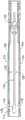
图17A示出了在成形之后但在机加工之前的类似于图16的下钳口主体(212a)。如图17A至图17B所示,侧壁(218,220)相对于底壁(216)具有钝角内角(θ1)。更具体地,在底壁(216)和侧壁(218)之间存在钝角内角(θ1),并且在底壁(216)和侧壁(220)之间存在钝角内角(θ1)。钝角内角(θ1)提供合适的拔模角以供模具(例如,金属注塑成型模具)被移除。例如,0.75度至1.5度的拔模角将导致大约90.75度至91.50度的钝角(θ1)。如图17A所示,细长通道(224a)不完全穿过底壁(216)而形成。在图17A中,下钳口主体(212a)可具有由连续实线限定的近终形状。如本文所用,“近终形状”是指初始成形操作产生非常接近最后(终)形状的中间(近终)形状,这降低了显著表面修整的需要和相关成本。这些初始成形操作可包括例如增材制造、选择性激光熔化、直接金属激光烧结和/或金属注塑成型。例如,如果所需操作需要更严格的公差,则这可能是有利的。图17A中的虚线示出了待移除的材料(例如,在一个或多个机加工步骤期间)。Figure 17A shows a lower jaw body (212a) similar to Figure 16 after forming but before machining. As shown in FIGS. 17A-17B , side walls ( 218 , 220 ) have an obtuse interior angle (θ1 ) with respect to bottom wall ( 216 ). More specifically, an obtuse interior angle (θ1) exists between the bottom wall (216) and the side wall (218), and an obtuse interior angle (θ1) exists between the bottom wall (216) and the side wall (220). The obtuse internal angle (θ1) provides a suitable draft angle for the mold (eg, metal injection molding mold) to be removed. For example, a draft angle of 0.75 to 1.5 degrees will result in an obtuse angle (θ1 ) of approximately 90.75 to 91.50 degrees. As shown in Figure 17A, the elongated channel (224a) is not formed completely through the bottom wall (216). In Figure 17A, the lower jaw body (212a) may have a near-net shape defined by continuous solid lines. As used herein, "near-net shape" means that the initial forming operation produces an intermediate (near-net) shape that is very close to the final (net) shape, which reduces the need for and associated costs of significant surface modification. These initial shaping operations may include, for example, additive manufacturing, selective laser melting, direct metal laser sintering, and/or metal injection molding. This may be advantageous, for example, if the desired operation requires tighter tolerances. The dashed lines in Figure 17A show material to be removed (eg, during one or more machining steps).
图17B示出了在部分机加工之后但在弯曲之前的图17A的下钳口主体(212a)。如图17B所示,细长通道(224)被机加工成完全延伸穿过下钳口主体(212)。更具体地,细长通道(224)完全延伸穿过底壁(216)的内表面(226a)和外表面(228)。如图17B所示,下钳口主体(212)的内表面(226a-226c)包括在下钳口主体(212)成形之后被机加工到下钳口主体(212)中的阶梯式表面。下部刀轨道(252a-252b)也被机加工到下钳口主体(212)中。例如,下部刀轨道(152a-152b)可接收图6中相对于器械(10)所示的击发梁盖(44)。Figure 17B shows the lower jaw body (212a) of Figure 17A after partial machining but before bending. As shown in Figure 17B, the elongated channel (224) is machined to extend completely through the lower jaw body (212). More specifically, elongated channel (224) extends completely through inner surface (226a) and outer surface (228) of bottom wall (216). As shown in FIG. 17B , inner surfaces ( 226a - 226c ) of lower jaw body ( 212 ) include stepped surfaces that are machined into lower jaw body ( 212 ) after lower jaw body ( 212 ) is formed. Lower knife tracks (252a-252b) are also machined into lower jaw body (212). For example, lower knife tracks (152a-152b) may receive firing beam cover (44) shown in FIG. 6 relative to instrument (10).
如图17B和图17C所示,下钳口主体(212)包括邻近细长通道(224)设置在底壁(216)中的至少一个对准特征部(234)。对准特征部(234)被构造成能够有助于将细长盖(214)与细长通道(224)对准。对准特征部(234)可与细长盖(214)能够固定地联接以至少部分地包封细长通道(224)。例如,在细长盖(214)与下钳口主体(212)能够固定地联接(例如,焊接)之前和期间,对准特征部(234)可有助于在下钳口主体(212)上对准和保持细长盖(214)。如图所示,对准特征部(234)包括第一凹陷部分(236)和第二凹陷部分(238)。第一凹陷部分(236)和第二凹陷部分(238)设置在底壁(216)的外表面(228)与下部刀轨道(252a-252b)之间。第一凹陷部分(236)和第二凹陷部分(238)分别包括由细长通道(224)分开的第一凹陷表面(240)和第二凹陷表面(242)。如图所示,第一凹陷部分(236)的第一凹陷表面(240)和第二凹陷部分(238)的第二凹陷表面(242)通向细长通道(224)并且大致垂直于细长通道(224)。As shown in FIGS. 17B and 17C , lower jaw body ( 212 ) includes at least one alignment feature ( 234 ) disposed in bottom wall ( 216 ) adjacent elongated channel ( 224 ). Alignment feature (234) is configured to facilitate alignment of elongated cover (214) with elongated channel (224). Alignment feature (234) can be fixably coupled with elongated cover (214) to at least partially enclose elongated channel (224). For example, alignment features (234) may facilitate alignment on lower jaw body (212) before and during elongated cover (214) and lower jaw body (212) can be fixedly coupled (eg, welded). Align and maintain the elongated cover (214). As shown, the alignment feature (234) includes a first recessed portion (236) and a second recessed portion (238). The first recessed portion (236) and the second recessed portion (238) are disposed between the outer surface (228) of the bottom wall (216) and the lower knife track (252a-252b). The first recessed portion (236) and the second recessed portion (238) respectively include a first recessed surface (240) and a second recessed surface (242) separated by an elongated channel (224). As shown, the first recessed surface (240) of the first recessed portion (236) and the second recessed surface (242) of the second recessed portion (238) open into the elongated channel (224) and are generally perpendicular to the elongated channel (224).
如图17C所示,相对于底壁(216)弯曲侧壁(218,220)以具有大约90度的内角(θ2)。更具体地,朝底壁(216)弯曲侧壁(218)并且朝底壁(216)弯曲侧壁(220),使得钝角(θ1)具有大约90度的角度(θ2)。因此,组织止挡件在大约0度处为直的。外部凹口(270)也被机加工到相对的侧壁(218,220)中。As shown in Figure 17C, the side walls (218, 220) are curved relative to the bottom wall (216) to have an interior angle (θ2) of approximately 90 degrees. More specifically, sidewall (218) is curved toward bottom wall (216) and sidewall (220) is curved toward bottom wall (216) such that obtuse angle (θ1) has an angle (θ2) of approximately 90 degrees. Thus, the tissue stop is straight at approximately 0 degrees. External recesses (270) are also machined into the opposing side walls (218, 220).
C.制造下钳口的示例性方法C. Exemplary method of fabricating the lower jaw
图18示出了制造外科器械(10)的端部执行器(12)的下钳口(110,210)的方法(310),该方法包括至少五个步骤(312,314,316,318,320)。如图所示,在步骤(312)处,方法(310)包括使用金属注塑成型工艺并使用金属注塑成型机(322)来形成下钳口主体(112,212),使得细长通道(124,224)不完全延伸穿过下钳口主体(112,212)。如前所述,下钳口主体(112,212)可经历热等静压过程。在步骤(314)处,方法(310)还包括随后使用车床(324)机加工细长通道(124,224)以完全延伸穿过下钳口主体(112,212),其中细长通道(124,224)被构造成能够接收刀的穿过该细长通道的一部分。18 shows a method (310) of manufacturing a lower jaw (110, 210) of an end effector (12) of a surgical instrument (10), the method comprising at least five steps (312, 314, 316, 318, 320). As shown, at step (312), the method (310) includes using a metal injection molding process and using a metal injection molding machine (322) to form the lower jaw body (112, 212) such that the elongated channel (124, 224) is incomplete Extends through the lower jaw body (112,212). As previously mentioned, the lower jaw body (112, 212) may undergo a hot isostatic pressing process. At step (314), the method (310) further includes subsequently machining the elongated channel (124, 224) using a lathe (324) to extend completely through the lower jaw body (112, 212), wherein the elongated channel (124, 224) is configured to A portion of a knife can be received through the elongated passage.
在步骤(316)处,方法(310)还包括使用压机(326)向内弯曲下钳口主体(112,212)的第一向外延伸的侧面和第二向外延伸的侧面(例如,相对的侧壁118,120,218,220)以与细长通道(124,224)大致垂直。在步骤(318)处,方法(310)还包括使用下钳口主体(112,212)的邻近细长通道(124,224)设置的至少一个对准特征部(134,234)来将细长盖(114,214)与完全延伸穿过下钳口主体(112,212)的细长通道(124,224)对准。在步骤(320)处,方法(310)还包括使用焊接机(328)将细长盖(114,214)焊接到下钳口主体(112,212)上以至少部分地包封细长通道(124,224)。At step (316), the method (310) further includes bending the first and second outwardly extending sides (e.g., opposite sides) of the lower jaw body (112, 212) inwardly using a press (326). The sidewalls (118, 120, 218, 220) are generally perpendicular to the elongated channel (124, 224). At step (318), the method (310) further includes aligning the elongated cover (114, 214) with the full Elongated channels (124, 224) extending through lower jaw bodies (112, 212) are aligned. At step (320), the method (310) further includes welding the elongated cover (114, 214) to the lower jaw body (112, 212) to at least partially enclose the elongated channel (124, 224) using a welding machine (328).
D.第一示例性另选砧座D. First Exemplary Alternative Anvil
图19至图29示出了被构造成能够代替器械(10)的砧座(18)使用的第一示例性另选砧座(410)。更具体地,图19示出了包括第一示例性砧座主体(412)和第三示例性细长盖(414)的砧座(410),并且图20示出了砧座(410)的左下透视图。砧座主体(412)包括置于相对的侧壁(418,420)之间的顶壁(416)。顶壁(416)包括多个钉成形凹坑(422),如将参考图26A至图29更详细地讨论的。顶壁(416)包括延伸穿过顶壁(416)的内表面(426)和外表面(428)的细长通道(424)。如图19和图20所示,砧座主体(412)包括被构造成能够与下钳口(110,210)的近侧孔(160a,260a)能够枢转地相互作用的第一销(430)和第二销(432)。19-29 illustrate a first exemplary alternative anvil (410) configured to be used in place of anvil (18) of instrument (10). More specifically, Figure 19 shows an anvil (410) comprising a first exemplary anvil body (412) and a third exemplary elongated cover (414), and Figure 20 shows the anvil (410) Bottom left perspective view. The anvil body (412) includes a top wall (416) disposed between opposing side walls (418, 420). Top wall (416) includes a plurality of staple forming pockets (422), as will be discussed in more detail with reference to FIGS. 26A-29. The top wall (416) includes an elongated channel (424) extending through an inner surface (426) and an outer surface (428) of the top wall (416). As shown in Figures 19 and 20, the anvil body (412) includes a first pin (430) configured to pivotally interact with a proximal hole (160a, 260a) of the lower jaw (110, 210) and Second pin (432).
如图19和图23A至图25B所示,砧座主体(412)包括邻近细长通道(424)设置在顶壁(416)中的至少一个对准特征部(434)。对准特征部(434)被构造成能够有助于将细长盖(414)与细长通道(424)对准。对准特征部(434)可与细长盖(414)能够固定地联接以至少部分地包封细长通道(424)。例如,在细长盖(414)与砧座主体(412)能够固定地联接(例如,焊接)之前和期间,对准特征部(134)可有助于在砧座主体(412)上对准和保持细长盖(414)。如图所示,对准特征部(434)包括第一凹陷部分(436)和第二凹陷部分(438)。第一凹陷部分(436)和第二凹陷部分(438)设置在顶壁(416)的外表面(428)与上部刀轨道(444a-444b)之间。如图19中使用影线所示,可机加工细长盖(414)的内表面以及第一凹陷部分(436)和第二凹陷部分(438)以改善尺寸公差。上部刀轨道(444a-444b)被构造成能够接收图3至图6中相对于器械(10)的端部执行器(12)所示的上部销(38)。图23A示出了在被成形之后但在被机加工以移除图19、图22和图23A所示的机加工部分(445)之前的图20的砧座主体(412a)。图23B示出了在被机加工之后的图23A的砧座主体(412)。第一凹陷部分(436)包括被示为大致垂直于细长通道(424)的凹陷表面(440)和邻接凹陷表面(440)的向外延伸的侧向内表面(446)。类似地,第二凹陷部分(438)包括被示为大致垂直于细长通道(424)的凹陷表面(442)和邻接凹陷表面(440)的向外延伸的侧向内表面(448)。第一凹陷部分(436)的第一凹陷表面(440)和第二凹陷部分(438)的第二凹陷表面(442)由细长通道(424)分开。如图所示,第一凹陷部分(436)的第一凹陷表面(440)和第二凹陷部分(438)的第二凹陷表面(442)通向细长通道(424)并且大致垂直于细长通道(424)。As shown in FIGS. 19 and 23A-25B , the anvil body ( 412 ) includes at least one alignment feature ( 434 ) disposed in the top wall ( 416 ) adjacent to the elongated channel ( 424 ). Alignment feature (434) is configured to facilitate alignment of elongated cover (414) with elongated channel (424). Alignment feature (434) can be fixably coupled with elongated cover (414) to at least partially enclose elongated channel (424). For example, alignment features (134) may facilitate alignment on anvil body (412) before and during elongated cover (414) and anvil body (412) can be fixedly coupled (e.g., welded). and keep the elongated cap (414). As shown, the alignment feature (434) includes a first recessed portion (436) and a second recessed portion (438). The first recessed portion (436) and the second recessed portion (438) are disposed between the outer surface (428) of the top wall (416) and the upper knife track (444a-444b). As shown using hatching in FIG. 19, the inner surface of the elongated cover (414) and the first and second recessed portions (436, 438) may be machined to improve dimensional tolerances. The upper knife tracks (444a-444b) are configured to receive the upper pin (38) shown in FIGS. 3-6 with respect to the end effector (12) of the instrument (10). Figure 23A shows the anvil body (412a) of Figure 20 after being formed but before being machined to remove the machined portion (445) shown in Figures 19, 22 and 23A. Figure 23B shows the anvil body (412) of Figure 23A after being machined. First recessed portion (436) includes a recessed surface (440) shown generally perpendicular to elongated channel (424) and an outwardly extending lateral interior surface (446) adjoining recessed surface (440). Similarly, second recessed portion (438) includes a recessed surface (442) shown generally perpendicular to elongated channel (424) and an outwardly extending lateral interior surface (448) adjoining recessed surface (440). The first recessed surface (440) of the first recessed portion (436) and the second recessed surface (442) of the second recessed portion (438) are separated by an elongated channel (424). As shown, the first recessed surface (440) of the first recessed portion (436) and the second recessed surface (442) of the second recessed portion (438) open into the elongated channel (424) and are generally perpendicular to the elongated channel (424).
图21示出了在被机加工之前的图19的砧座主体(412)的左下透视图。虽然钉成形凹坑(422)未被示为被施加,但钉成形凹坑(422)可在砧座主体(412)成形(例如,使用金属注塑成型工艺)时被施加。如图19和图20所示,砧座主体(412)的第一销(430)和第二销(432)被机加工以改善与近侧孔(160a,260a)的相互作用。图22示出了图20的左下剖面透视图,其示出了被构造成能够使用一种或多种机加工工艺移除的机加工部分(445)。Figure 21 shows a bottom left perspective view of the anvil body (412) of Figure 19 prior to being machined. While staple forming pockets (422) are not shown as being applied, staple forming pockets (422) may be applied while anvil body (412) is being formed (eg, using a metal injection molding process). As shown in FIGS. 19 and 20, first pin (430) and second pin (432) of anvil body (412) are machined to improve interaction with proximal holes (160a, 260a). Figure 22 shows the lower left cutaway perspective view of Figure 20 showing the machined portion (445) configured to be removable using one or more machining processes.
图24A示出了包括图23B的砧座主体(412)和图19的细长盖(414)的砧座(410A)。图24A和图25A共同示出了在将细长盖(414)焊接到砧座主体(412)上之后,在细长盖(414)的细长侧向外侧面(450,452)与砧座主体(412)的细长通道(424)的向外延伸的侧向内表面(446,448)之间存在侧向间隙(G1)。例如,根据一个具体实施方案,侧向间隙(G1)可为0.001英寸至0.003英寸。然而,应当设想到,间隙(G1)可有所变化。如图24A至图25B所示,细长盖(414)包括第一细长侧向外侧面(450)和第二细长侧向外侧面(452)以及相对的内表面(456)和外表面(458)。细长盖(414)焊接到下钳口主体(412)上以至少部分地包封细长通道(424)。细长盖(414)的内表面(456)的至少一部分能够固定地联接(例如,焊接)到由细长通道(424)分开的第一凹陷部分(436)的第一凹陷表面(440)和第二凹陷部分(438)的第二凹陷表面(442)上。可通过将第一细长侧向外侧面(450)与向外延伸的侧向内表面(446)焊接在一起并且通过将第二细长侧向外侧面(452)与向外延伸的侧向内表面(448)焊接在一起来将细长盖(414)焊接到下钳口主体(412)上。如图所示,细长盖(414)的外表面(458)被构造成能够与底壁(416)的外表面(428)大致齐平地延伸。然而,一个或多个焊缝可从间隙(G1)突出。FIG. 24A shows an anvil ( 410A) comprising the anvil body ( 412 ) of FIG. 23B and the elongated cover ( 414 ) of FIG. 19 . 24A and 25A collectively show that after the elongated cover (414) has been welded to the anvil body (412), where the elongated lateral sides (450, 452) of the elongated cover (414) are aligned with the anvil body ( A lateral gap (G1) exists between outwardly extending lateral inner surfaces (446, 448) of the elongated channel (424) of 412). For example, according to one particular embodiment, the lateral gap (G1) may be 0.001 inches to 0.003 inches. However, it is contemplated that the gap (G1) may vary. As shown in Figures 24A-25B, the elongated cover (414) includes a first elongated lateral lateral side (450) and a second elongated lateral lateral side (452) and opposing inner (456) and outer surfaces (458). An elongated cover (414) is welded to the lower jaw body (412) to at least partially enclose the elongated channel (424). At least a portion of the inner surface (456) of the elongated cover (414) can be fixedly coupled (e.g., welded) to the first recessed surface (440) and the first recessed portion (436) separated by the elongated channel (424) on the second recessed surface (442) of the second recessed portion (438). can be achieved by welding the first elongated laterally outer side (450) to the outwardly extending laterally inner surface (446) and by welding the second elongated laterally outer side (452) to the outwardly extending laterally The inner surfaces (448) are welded together to weld the elongated cover (414) to the lower jaw body (412). As shown, outer surface (458) of elongated cover (414) is configured to extend substantially flush with outer surface (428) of bottom wall (416). However, one or more welds may protrude from the gap (G1).
如图24B和图25B所示,细长盖(414a)包括邻近内表面(456a)的凹口(454),该内表面包括平坦表面(460)。更具体地,图24B示出了细长盖(414a)和图23B的砧座主体(412a)。图25B示出了图24B的砧座主体(412a)和细长盖(414a)之间的配合的放大部分。如图所示,细长盖(414a)的外表面(458a)不包括凹口。外表面(458a)与顶壁(416)的外表面(428)大致齐平。然而,应当设想到包括弓形表面的各种凹口(454),并且还应当设想到V形表面。相比于图24A和图25A所示的细长盖(414),可沿着凹口(454)弯曲细长盖(414a)以减小侧向间隙(G1)。例如,图25B中的侧向间隙(G2)小于0.001英寸。可通过将第一细长侧向外侧面(450a)与向外延伸的侧向内表面(446)焊接在一起并且通过将第二细长侧向外侧面(452a)与向外延伸的侧向内表面(448)焊接在一起来将细长盖(414a)焊接到下钳口主体(412)上。如图所示,细长盖(414a)的外表面(458a)被构造成能够与底壁(416)的外表面(428)大致齐平地延伸。然而,一个或多个焊缝可从间隙(G2)突出。As shown in Figures 24B and 25B, the elongated cover (414a) includes a notch (454) adjacent the inner surface (456a), which includes a planar surface (460). More specifically, Figure 24B shows the elongated cover (414a) and the anvil body (412a) of Figure 23B. Figure 25B shows an enlarged portion of the fit between the anvil body (412a) and elongated cap (414a) of Figure 24B. As shown, the outer surface (458a) of the elongated cover (414a) does not include a notch. The outer surface (458a) is substantially flush with the outer surface (428) of the top wall (416). However, various recesses (454) including arcuate surfaces are contemplated, and V-shaped surfaces are also contemplated. The elongated cover (414a) can be bent along the notch (454) to reduce the lateral gap (Gl) compared to the elongated cover (414) shown in Figures 24A and 25A. For example, the lateral gap (G2) in Figure 25B is less than 0.001 inches. can be obtained by welding the first elongated lateral outer side (450a) to the outwardly extending lateral inner surface (446) and by welding the second elongated lateral lateral side (452a) to the outwardly extending lateral The inner surfaces (448) are welded together to weld the elongated cover (414a) to the lower jaw body (412). As shown, the outer surface (458a) of the elongated cover (414a) is configured to extend substantially flush with the outer surface (428) of the bottom wall (416). However, one or more welds may protrude from the gap (G2).
如图所示,砧座主体(412)和细长盖(414,414a)各自一体地成形为单件并且随后联接在一起。例如,砧座主体(412)和细长盖(414)可使用多种工艺(包括金属注塑成型)单独地成形。金属注塑成型(MIM)是指任何金属机加工工艺,其中将细粉末状金属与粘结剂材料混合以产生原料,该原料随后使用模塑工艺(诸如注塑成型)来成型和固化。金属注塑成型允许大量的复杂部件被成型。砧座主体(412)及其相应特征部中的每个特征部具有模塑形状。As shown, the anvil body (412) and elongated cover (414, 414a) are each integrally formed as a single piece and subsequently coupled together. For example, anvil body (412) and elongated cap (414) may be separately formed using a variety of processes, including metal injection molding. Metal Injection Molding (MIM) refers to any metal machining process in which finely powdered metal is mixed with a binder material to produce a feedstock that is then shaped and cured using a molding process such as injection molding. Metal injection molding allows a large number of complex parts to be molded. Each of the anvil body (412) and its corresponding features has a molded shape.
砧座主体的某些特征部可随后被机加工成机加工形状。机加工某些特征部可提供许多有益效果,包括改善金属注塑成型工艺的尺寸公差。然而,应当设想到,如果需要,这些部件中的两个或更多个部件可一起一体地成形为单件。然而,砧座主体(412)可使用多种工艺来成形,包括增材制造、选择性激光熔化、直接金属激光烧结和/或金属注塑成型。某些制造工艺(冲压、增材制造、选择性激光熔化、直接金属激光烧结和/或金属注塑成型)可导致比期望更宽松的公差。鉴于制造器械(10)所需的严格公差,期望精制砧座主体(412)的至少某些特定部分以改善砧座主体(412)的尺寸精度。Certain features of the anvil body may subsequently be machined into the machined shape. Machining certain features can provide a number of benefits, including improving dimensional tolerances of the metal injection molding process. However, it is contemplated that two or more of these components could be integrally formed together as a single piece, if desired. However, the anvil body (412) can be formed using a variety of processes, including additive manufacturing, selective laser melting, direct metal laser sintering, and/or metal injection molding. Certain manufacturing processes (stamping, additive manufacturing, selective laser melting, direct metal laser sintering, and/or metal injection molding) can result in looser tolerances than desired. In view of the tight tolerances required to manufacture instrument (10), it is desirable to refine at least certain portions of anvil body (412) to improve the dimensional accuracy of anvil body (412).
钉成形凹坑(422)可与砧座主体(412)同时形成或在砧座主体(412)形成之后形成。例如,图21示出了砧座主体(412)的透视图,但其中钉成形凹坑(422)尚未形成。如参考图20更详细地描述,如果需要,可在形成砧座主体(412)之后机加工砧座主体(412)的至少一部分。Staple forming pockets (422) may be formed simultaneously with anvil body (412) or formed after anvil body (412) is formed. For example, Figure 21 shows a perspective view of the anvil body (412), but in which the staple forming pockets (422) have not yet been formed. As described in more detail with reference to FIG. 20, at least a portion of the anvil body (412) may be machined, if desired, after the anvil body (412) is formed.
如图26A至图29所示,在使用注塑成型工艺(例如,金属注塑成型工艺)形成钉成形凹坑(422)之后,可压印或电化学加工钉成形凹坑(422)的至少一部分。更具体地,图26A示出了在压印或电化学加工之前的钉成形凹坑(422a),而图26B示出了在压印或电化学加工之后的图26A的钉成形凹坑(422)。如图26A所示,钉成形凹坑(422a)包括设置在外部部分(464a,466a)之间的中心部分(462a)。如图26B、图27B和图28B所示,钉成形凹坑(422)的中心部分(462)随后被压印或电化学加工,这导致比未被压印或电化学加工的另一部分(例如,外部部分(464,466))更平滑的表面和更致密的表面。因此,外部部分(464,466)具有比钉成形凹坑(422)的中心部分(462)更粗糙且更小密度的表面。换句话讲,钉成形凹坑(422)的未机加工部分(例如,外部部分(464a,466a))具有第一表面光洁度,并且钉成形凹坑(422)的机加工部分(例如,中心部分(462))具有第二表面光洁度,其中第二表面光洁度比第一表面光洁度更精细。另选地,如果需要,可压印或电化学加工整个钉成形凹坑(422),包括外部部分(464,466)。As shown in FIGS. 26A-29 , after the staple-forming pockets ( 422 ) are formed using an injection molding process (eg, a metal injection molding process), at least a portion of the staple-forming pockets ( 422 ) can be embossed or electrochemically machined. More specifically, FIG. 26A shows the staple forming pocket (422a) before imprinting or electrochemical machining, while FIG. 26B shows the staple forming pocket (422a) of FIG. 26A after imprinting or electrochemical machining. ). As shown in FIG. 26A, staple forming pocket (422a) includes a central portion (462a) disposed between outer portions (464a, 466a). As shown in Figures 26B, 27B and 28B, the central portion (462) of the staple forming pocket (422) is subsequently embossed or electrochemically machined, which results in a larger portion than the other portion that is not embossed or electrochemically machined (e.g. , outer part (464,466)) smoother surface and denser surface. Thus, outer portions (464, 466) have a rougher and less dense surface than central portion (462) of staple forming pocket (422). In other words, unmachined portions (e.g., outer portions (464a, 466a)) of staple forming pockets (422) have the first surface finish, and machined portions (e.g., center Portion (462)) has a second surface finish, wherein the second surface finish is finer than the first surface finish. Alternatively, the entire staple forming pocket (422), including outer portions (464, 466), may be embossed or electrochemically machined, if desired.
“压印”为精密冲压的形式,其中工件经受足够高的应力以在材料的表面上引起塑性流动。塑性流动减小了表面晶粒尺寸并使工件的表面硬化,而工件内较深的材料保持其韧性和延展性。压印还改善了钉成形凹坑(422)的尺寸公差。电化学加工(ECM)为使用一种或多种电化学工艺移除金属的方法。电化学加工可因成本效益而用于批量生产,并且用于加工极硬材料或者难以使用常规方法机加工的材料。电化学加工可在硬质金属工件中切割小的或独特形状的角度、复杂的轮廓或腔体。"Indentation" is a form of precision stamping in which the workpiece is subjected to sufficiently high stresses to induce plastic flow on the surface of the material. Plastic flow reduces surface grain size and hardens the surface of the workpiece, while material deeper within the workpiece retains its toughness and ductility. Embossing also improves the dimensional tolerance of the staple forming pockets (422). Electrochemical machining (ECM) is a method of removing metals using one or more electrochemical processes. Electrochemical machining can be used cost-effectively for mass production and for machining extremely hard materials or materials that are difficult to machine using conventional methods. Electrochemical machining cuts small or uniquely shaped angles, complex contours or cavities in hard metal workpieces.
图27A示出了沿图26A的线27A-27A截取的钉成形凹坑(422a)的中心部分(462a),而图27B示出了沿图26B的线27B-27B截取的钉成形凹坑(422)的中心部分(462)。如图所示,当将图27A与图27B进行比较时,已被压印或电化学加工的中心部分(462a)比未被压印或电化学加工的相同钉成形凹坑(422)的另一部分(例如,外部部分(464,466))更平滑且更致密。Figure 27A shows the central portion (462a) of the staple forming pocket (422a) taken along
图28A示出了沿线28A-28A截取的图26A的钉成形凹坑(422a)的一部分,而图28B示出了沿线28B-28B截取的图26B的钉成形凹坑(422)的一部分。如图所示,当将图28A与图28B进行比较时,在压印或电化学加工工艺之后产生通道(468)。图29示出了在被压印或电化学加工之后的图26B的多个钉成形凹坑(422)。更具体地,中心部分(462)被压印或电化学加工。Figure 28A shows a portion of the staple forming pocket (422a) of Figure 26A taken along
D.第二示例性另选砧座D. Second Exemplary Alternative Anvil
图30示出了被构造成能够代替砧座(18)使用的第二示例性另选砧座(510)。类似于其中类似的附图标号表示类似的特征部的砧座(410),砧座(510)包括砧座主体(512)和细长盖(514)。类似于砧座主体(412),砧座主体(512)包括顶壁(516)、相对的侧壁(518,520)、细长通道(524)、内表面(未示出)、外表面(528)、第一销(530)、第二销(532)、至少一个对准特征部(534)、第一凹陷部分(536)、第二凹陷部分(538)、凹陷表面(540)、上部刀轨道(544a)和机加工部分(545)。上部刀轨道(544a)被构造成能够接收图3至图6中相对于器械(10)的端部执行器(12)所示的上部销(38)。类似于细长盖(414),细长盖(514)包括第一细长侧向外侧面(550)和第二细长侧向外侧面(552)以及相对的内表面(556)和外表面(558)。在使用一种或多种机加工工艺形成砧座主体(512)之后,可移除机加工部分(545)。类似于钉成形凹坑(422),砧座(510)也包括未被示出的多个钉成形凹坑。Figure 30 illustrates a second exemplary alternative anvil (510) configured to be used in place of anvil (18). Similar to anvil ( 410 ) in which like reference numerals represent like features, anvil ( 510 ) includes an anvil body ( 512 ) and an elongated cover ( 514 ). Similar to the anvil body (412), the anvil body (512) includes a top wall (516), opposing side walls (518, 520), an elongated channel (524), an inner surface (not shown), an outer surface (528) , first pin (530), second pin (532), at least one alignment feature (534), first recessed portion (536), second recessed portion (538), recessed surface (540), upper knife track (544a) and machined part (545). The upper knife track (544a) is configured to receive the upper pin (38) shown in FIGS. 3-6 with respect to the end effector (12) of the instrument (10). Similar to the elongated cover (414), the elongated cover (514) includes a first elongated laterally outer side (550) and a second elongated laterally outer side (552) and opposing inner (556) and outer surfaces (558). After the anvil body (512) is formed using one or more machining processes, the machined portion (545) may be removed. Similar to staple forming pockets (422), anvil (510) also includes a plurality of staple forming pockets, not shown.
E.制造砧座的示例性方法E. Exemplary Methods of Making Anvils
图31示出了制造外科器械(10)的端部执行器(12)的砧座(410,510)的方法(610),该方法包括至少五个步骤(612,614,616,618,620)。在步骤(612)处,方法(610)包括使用金属注塑成型工艺形成砧座主体(412,512),使得细长通道(424,524)不完全延伸穿过砧座主体(412,512)。可例如使用金属注塑成型机(622)来执行步骤(612)。然而,还应当设想到,可使用增材制造来形成砧座主体(412,512)。Fig. 31 shows a method (610) of manufacturing an anvil (410, 510) of an end effector (12) of a surgical instrument (10), the method comprising at least five steps (612, 614, 616, 618, 620). At step (612), the method (610) includes forming the anvil body (412, 512) using a metal injection molding process such that the elongated channel (424, 524) does not extend completely through the anvil body (412, 512). Step (612) may be performed, for example, using a metal injection molding machine (622). However, it is also contemplated that additive manufacturing may be used to form the anvil body (412, 512).
在步骤(614)处,方法(610)包括随后机加工细长通道(424,524)以完全延伸穿过砧座主体(412,512),其中细长通道(424,524)被构造成能够接收刀的穿过该细长通道的一部分(例如,上部销(38))。例如,上部刀轨道(444a-444b,544a)被构造成能够接收图3至图6中相对于器械(10)的端部执行器(12)所示的上部销(38)。应当设想到,细长通道(424,524)的机加工可发生在钉成形凹坑(422,522)的压印之前、同时或之后。可使用多种机加工工具,例如使用可手动操作或自动化的车床(624)来执行步骤(612)。使用近终形状的示例性方法(610)通过提供已施加有一个或多个特征部的砧座(410,510)来降低对昂贵机加工的需要。At step (614), the method (610) includes subsequently machining the elongated channel (424, 524) to extend completely through the anvil body (412, 512), wherein the elongated channel (424, 524) is configured to receive a knife through the A portion of an elongated channel (eg, upper pin (38)). For example, upper knife track (444a-444b, 544a) is configured to receive upper pin (38) shown in FIGS. 3-6 with respect to end effector (12) of instrument (10). It is contemplated that machining of the elongated channels (424, 524) may occur prior to, concurrently with, or after embossing of the staple forming pockets (422, 522). Step (612) may be performed using a variety of machining tools, such as using a manually operable or automated lathe (624). An exemplary method (610) of using a near-net shape reduces the need for expensive machining by providing an anvil (410, 510) already applied with one or more features.
在步骤(616)处,方法(610)包括使用压机(626)压印或电化学加工至少一个钉成形凹坑(422,522)的至少一部分。在步骤(618)处,方法(610)包括使用砧座主体(412,512)的邻近细长通道(424,524)设置的至少一个对准特征部来将细长盖(414,514)与完全延伸穿过砧座主体(412,512)的细长通道(424,524)对准。在步骤(620)处,方法(610)包括使用焊接机(628)将细长盖(414,514)焊接到砧座主体(412,512)上以至少部分地包封细长通道(424,524)。At step (616), method (610) includes embossing or electrochemically machining at least a portion of at least one staple forming pocket (422, 522) using a press (626). At step (618), the method (610) includes using at least one alignment feature of the anvil body (412, 512) disposed adjacent the elongated channel (424, 524) to align the elongated cover (414, 514) with the The elongated channels (424,524) of the bodies (412,512) are aligned. At step (620), the method (610) includes welding the elongated cover (414, 514) to the anvil body (412, 512) using a welding machine (628) to at least partially enclose the elongated channel (424, 524).
III.示例性组合III. Exemplary Combinations
以下实施例涉及本文的教导内容可被组合或应用的各种非穷尽性方式。应当理解,以下实施例并非旨在限制可在本专利申请或本专利申请的后续提交文件中的任何时间提供的任何权利要求的覆盖范围。不旨在进行免责声明。提供以下实施例仅仅是出于例示性目的。预期本文的各种教导内容可按多种其他方式进行布置和应用。还设想到,一些变型可省略在以下实施例中所提及的某些特征。因此,下文提及的方面或特征中的任一者均不应被视为决定性的,除非另外例如由发明人或关注发明人的继承者在稍后日期明确指明如此。如果本专利申请或与本专利申请相关的后续提交文件中提出的任何权利要求包括下文提及的那些特征之外的附加特征,则这些附加特征不应被假定为因与专利性相关的任何原因而被添加。The following examples relate to various non-exhaustive ways in which the teachings herein can be combined or applied. It should be understood that the following examples are not intended to limit the scope of coverage of any claims that may be presented at any time in this patent application or a subsequent filing of this patent application. No disclaimer of liability is intended. The following examples are provided for illustrative purposes only. It is contemplated that the various teachings herein can be arranged and applied in numerous other ways. It is also contemplated that some variations may omit certain features mentioned in the following embodiments. Accordingly, none of the aspects or features mentioned below should be considered conclusive unless expressly indicated otherwise at a later date, eg, by the inventor or successors of the concerned inventor. If any claims presented in this patent application or a subsequent filing related to this patent application include additional features other than those mentioned below, these additional features should not be presumed to be for any reason relevant to patentability and was added.
实施例1Example 1
一种制造外科器械的端部执行器的方法,其中所述端部执行器包括相对的第一钳口和第二钳口,其中所述第一钳口包括主体和细长盖,所述方法包括:(a)提供所述端部执行器的所述第一钳口的所述细长盖和所述主体,其中所述主体包括细长通道和至少一个对准特征部;(b)使用所述主体的邻近所述细长通道设置的所述至少一个对准特征部来将所述细长盖与完全延伸穿过所述主体的所述细长通道对准;以及(c)将所述细长盖焊接到所述主体上以至少部分地包封所述细长通道。A method of manufacturing an end effector for a surgical instrument, wherein the end effector includes opposed first and second jaws, wherein the first jaw includes a body and an elongated cover, the method comprising: (a) the elongate cover and the body providing the first jaw of the end effector, wherein the body includes an elongate channel and at least one alignment feature; (b) using said at least one alignment feature of said body disposed adjacent to said elongated channel to align said elongated cover with said elongated channel extending fully through said body; and (c) align said The elongated cover is welded to the body to at least partially enclose the elongated channel.
实施例2Example 2
根据实施例1所述的方法,其中,将所述细长盖焊接到所述主体上还包括将所述细长盖的内表面焊接到所述对准特征部的外表面上。The method of example 1, wherein welding the elongated cover to the body further comprises welding an inner surface of the elongated cover to an outer surface of the alignment feature.
实施例3Example 3
根据实施例1所述的方法,其中,所述对准特征部包括至少一个凹陷部分,所述至少一个凹陷部分包括凹陷表面,其中将所述细长盖焊接到所述主体上还包括将所述细长盖的内表面焊接到所述对准特征部的所述凹陷表面上。The method of example 1, wherein the alignment feature comprises at least one recessed portion, the at least one recessed portion comprising a recessed surface, and wherein welding the elongated cover to the body further comprises welding the An inner surface of the elongated cover is welded to the recessed surface of the alignment feature.
实施例4Example 4
根据实施例1所述的方法,其中,所述对准特征部包括第一凹陷部分和第二凹陷部分,其中所述第一凹陷部分和所述第二凹陷部分分别包括由所述细长通道分开的第一凹陷表面和第二凹陷表面,其中将所述细长盖焊接到所述主体上还包括将所述细长盖的内表面焊接到由所述细长通道分开的所述第一凹陷表面和所述第二凹陷表面上。The method of embodiment 1, wherein the alignment feature includes a first recessed portion and a second recessed portion, wherein the first recessed portion and the second recessed portion each include a separate first and second recessed surfaces, wherein welding the elongated cover to the body further includes welding an inner surface of the elongated cover to the first recessed surface separated by the elongated channel. the recessed surface and the second recessed surface.
实施例5Example 5
根据实施例4所述的方法,其中,所述第一凹陷部分和所述第二凹陷部分包括近侧弓形表面和远侧弓形表面,其中将所述细长盖与所述细长通道对准还包括通过使用所述近侧弓形表面和所述远侧弓形表面在近侧和在远侧对准所述细长盖。The method of example 4, wherein the first recessed portion and the second recessed portion comprise proximal and distal arcuate surfaces, wherein the elongate cap is aligned with the elongate channel Also included is aligning the elongate cap proximally and distally using the proximal arcuate surface and the distal arcuate surface.
实施例6Example 6
根据实施例1至5中任一项或多项所述的方法,其中,提供所述主体还包括使用金属注塑成型工艺形成所述主体,使得所述细长通道不完全延伸穿过所述主体;以及随后机加工所述细长通道以完全延伸穿过所述主体。The method of any one or more of embodiments 1-5, wherein providing the body further comprises forming the body using a metal injection molding process such that the elongate channel does not extend completely through the body ; and subsequently machining the elongated channel to extend completely through the body.
实施例7Example 7
根据实施例1至6中任一项或多项所述的方法,其中,所述主体包括砧座主体或下钳口主体,其中所述方法还包括将刀轨道的一部分机加工到所述砧座主体或所述下钳口主体中。The method of any one or more of embodiments 1-6, wherein the body comprises an anvil body or a lower jaw body, wherein the method further comprises machining a portion of the knife track to the anvil In the seat body or the lower jaw body.
实施例8Example 8
根据实施例1至7中任一项或多项所述的方法,其中,在将所述细长盖焊接到所述主体上之后,在所述细长盖的侧向外侧面与所述主体的所述细长通道的侧向内表面之间存在细长间隙。The method according to any one or more of embodiments 1 to 7, wherein after welding the elongated cover to the body, a laterally outer face of the elongated cover meets the body An elongated gap exists between the lateral inner surfaces of the elongated channel.
实施例9Example 9
根据实施例8所述的方法,其中,所述细长盖包括凹口,其中所述方法还包括沿着所述凹口弯曲所述细长盖以减小所述细长间隙。The method of example 8, wherein the elongated cover includes a notch, wherein the method further comprises bending the elongated cover along the notch to reduce the elongated gap.
实施例10Example 10
根据实施例1至9中任一项或多项所述的方法,其中,所述主体包括砧座主体或下钳口主体中的至少一者,其中提供所述第一钳口的所述细长盖和所述主体还包括金属注塑成型砧座主体或下钳口主体中的至少一者。The method according to any one or more of embodiments 1 to 9, wherein said body comprises at least one of an anvil body or a lower jaw body, wherein said thin portion of said first jaw is provided. The elongated cover and said body also include at least one of a metal injection molded anvil body or a lower jaw body.
实施例11Example 11
根据实施例1至10中任一项或多项所述的方法,其中,所述主体的所述至少一个对准特征部在焊接之前和在焊接期间均将所述细长盖与所述细长通道对准。The method according to any one or more of embodiments 1 to 10, wherein said at least one alignment feature of said body aligns said elongated cap with said elongated cap both before and during welding. Long channel alignment.
实施例12Example 12
根据实施例1至11中任一项或多项所述的方法,还包括:向内弯曲所述下钳口主体的第一向外延伸的侧面和第二向外延伸的侧面以与所述细长通道大致垂直。The method according to any one or more of embodiments 1-11, further comprising bending the first and second outwardly extending sides of the lower jaw body inwardly to align with the The elongated channel is generally vertical.
实施例13Example 13
根据实施例1至5和实施例8至9中任一项或多项所述的方法,其中,所述主体包括砧座主体,其中所述方法还包括金属注塑成型所述砧座主体的多个钉成形凹坑。The method of any one or more of embodiments 1-5 and embodiments 8-9, wherein the body comprises an anvil body, wherein the method further comprises metal injection molding multiple portions of the anvil body. nail forming dimples.
实施例14Example 14
根据实施例13所述的方法,其中,所述方法还包括在金属注塑成型所述多个钉成形凹坑之后,压印或电化学加工所述多个钉成形凹坑中的至少一个钉成形凹坑的至少一部分,其中压印或电化学加工的所述部分比未压印或电化学加工的另一部分更平滑且更致密。The method of
实施例15Example 15
根据实施例14所述的方法,其中,压印或电化学加工的所述部分为所述多个钉成形凹坑中的至少一个钉成形凹坑的中心部分。The method of example 14, wherein the embossed or electrochemically machined portion is a central portion of at least one staple forming pocket of the plurality of staple forming pockets.
实施例16Example 16
一种制造外科器械的端部执行器的方法,其中所述端部执行器包括相对的第一钳口和第二钳口,其中所述第一钳口包括主体和细长盖,其中所述主体包括细长通道,所述方法包括:(a)使用金属注塑成型工艺形成所述主体,使得所述细长通道不完全延伸穿过所述主体;(b)随后机加工细长通道以完全延伸穿过所述主体,其中所述细长通道被构造成能够接收刀的穿过所述细长通道的一部分;以及(c)将所述细长盖焊接到所述主体上以至少部分地包封所述细长通道。A method of manufacturing an end effector for a surgical instrument, wherein the end effector includes opposed first and second jaws, wherein the first jaw includes a body and an elongated cover, wherein the The body includes an elongated channel, the method comprising: (a) forming the body using a metal injection molding process such that the elongated channel does not extend completely through the body; (b) subsequently machining the elongated channel to completely extending through the main body, wherein the elongated passage is configured to receive a portion of a knife passing through the elongated passage; and (c) welding the elongated cover to the main body to at least partially Encapsulating the elongated channel.
实施例17Example 17
根据实施例16所述的方法,还包括:在将所述细长盖焊接到所述主体上之前机加工所述细长盖的内表面。The method of example 16, further comprising machining an inner surface of the elongated cover prior to welding the elongated cover to the body.
实施例18Example 18
一种器械,包括:(a)柄部部分;(b)轴,所述轴从所述柄部部分延伸;和(c)端部执行器,所述端部执行器与所述轴相连,其中所述端部执行器能够操作以压缩、缝合和切割组织,其中所述端部执行器包括下钳口和砧座,其中所述下钳口或所述砧座中的至少一者包括:(i)细长盖,所述细长盖包括相对的第一表面和第二表面,和(ii)主体,所述主体包括:(A)细长通道,所述细长通道完全延伸穿过所述主体,和(B)至少一个对准特征部,所述至少一个对准特征部邻近所述细长通道设置,其中所述对准特征部与所述细长盖的所述第一表面能够固定地联接以至少部分地包封所述细长通道。An instrument comprising: (a) a handle portion; (b) a shaft extending from the handle portion; and (c) an end effector coupled to the shaft, wherein the end effector is operable to compress, staple and cut tissue, wherein the end effector comprises a lower jaw and an anvil, wherein at least one of the lower jaw or the anvil comprises: (i) an elongated cover comprising opposed first and second surfaces, and (ii) a body comprising: (A) an elongated channel extending completely through said body, and (B) at least one alignment feature disposed adjacent said elongated channel, wherein said alignment feature is aligned with said first surface of said elongated cover Fixedly coupleable to at least partially enclose the elongate channel.
实施例19Example 19
根据实施例18所述的器械,其中,所述对准特征部包括至少一个凹陷部分,所述至少一个凹陷部分包括凹陷表面,其中所述细长盖的所述第一表面与所述对准特征部的所述凹陷表面能够固定地联接。The instrument of Example 18, wherein the alignment feature comprises at least one recessed portion comprising a recessed surface, wherein the first surface of the elongated cap is aligned with the alignment feature. The recessed surfaces of the features are fixedly coupleable.
实施例20Example 20
根据实施例18所述的器械,其中,所述对准特征部包括第一凹陷部分和第二凹陷部分,其中所述第一凹陷部分和所述第二凹陷部分分别包括由所述细长通道分开的第一凹陷表面和第二凹陷表面,其中所述细长盖的所述第一表面能够固定地联接到由所述细长通道分开的所述第一凹陷表面和所述第二凹陷表面上。The instrument of example 18, wherein the alignment feature comprises a first recessed portion and a second recessed portion, wherein the first recessed portion and the second recessed portion respectively comprise separate first and second recessed surfaces, wherein said first surface of said elongated cover is fixably coupled to said first and second recessed surfaces separated by said elongated channel superior.
实施例21Example 21
根据实施例18所述的器械,其中,所述对准特征部与所述细长盖的所述第一表面能够固定地联接以至少部分地包封所述细长通道。The instrument of Example 18, wherein the alignment feature and the first surface of the elongated cover are fixedly coupleable to at least partially enclose the elongated channel.
实施例22Example 22
根据实施例18至21中任一项或多项所述的器械,其中,所述细长盖的内表面焊接到所述对准特征部的外表面上。The instrument according to any one or more of Examples 18-21, wherein an inner surface of the elongated cover is welded to an outer surface of the alignment feature.
实施例23Example 23
根据实施例18所述的器械,其中,所述对准特征部包括至少一个凹陷部分,其中所述至少一个凹陷部分包括凹陷表面,其中所述细长盖的内表面焊接到所述对准特征部的所述凹陷表面上。The instrument of Example 18, wherein the alignment feature comprises at least one recessed portion, wherein the at least one recessed portion comprises a recessed surface, and wherein an inner surface of the elongated cap is welded to the alignment feature portion of the recessed surface.
实施例24Example 24
根据实施例18所述的器械,其中,所述对准特征部包括第一凹陷部分和第二凹陷部分,其中所述第一凹陷部分和所述第二凹陷部分分别包括由所述细长通道分开的第一凹陷表面和第二凹陷表面,其中所述细长盖的内表面焊接到由所述细长通道分开的所述第一凹陷表面和所述第二凹陷表面上。The instrument of example 18, wherein the alignment feature comprises a first recessed portion and a second recessed portion, wherein the first recessed portion and the second recessed portion respectively comprise Separate first and second recessed surfaces, wherein the inner surface of the elongated cover is welded to the first and second recessed surfaces separated by the elongated channel.
实施例25Example 25
根据实施例20和24中任一项或多项所述的器械,其中,所述第一凹陷部分和所述第二凹陷部分包括近侧弓形表面和远侧弓形表面,其中所述细长盖被构造成能够使用所述近侧弓形表面和所述远侧弓形表面在近侧和在远侧对准。The instrument according to any one or more of
实施例26Example 26
根据实施例18至25中任一项或多项所述的器械,其中,使用金属注塑成型工艺形成所述主体,使得所述细长通道不完全延伸穿过所述主体,其中所述细长通道随后被机加工以完全延伸穿过所述主体。The instrument according to any one or more of Examples 18-25, wherein said body is formed using a metal injection molding process such that said elongated channel does not extend completely through said body, wherein said elongated The channel is then machined to extend completely through the body.
实施例27Example 27
根据实施例18至26中任一项或多项所述的器械,其中,所述主体包括砧座主体或下钳口主体,其中刀轨道的一部分被机加工到所述砧座主体或所述下钳口主体中。An instrument according to any one or more of
实施例28Example 28
根据实施例18至27中任一项或多项所述的器械,其中,细长间隙在所述细长盖的侧向外侧面与所述主体的所述细长通道的侧向内表面之间延伸。The instrument according to any one or more of
实施例29Example 29
根据实施例18至28中任一项或多项所述的器械,其中,所述细长盖包括凹口,其中所述细长盖被构造成能够沿着所述凹口弯曲以减小所述间隙。The instrument according to any one or more of Examples 18-28, wherein the elongated cover includes a notch, wherein the elongated cover is configured to bend along the notch to reduce the said gap.
实施例30Example 30
根据实施例18至26和实施例28至29中任一项或多项所述的器械,其中,所述主体包括砧座主体或下钳口主体中的至少一者,其中砧座主体或下钳口主体中的至少一者使用金属注塑成型来形成。The instrument according to any one or more of embodiments 18-26 and embodiments 28-29, wherein the body comprises at least one of an anvil body or a lower jaw body, wherein the anvil body or the lower jaw body At least one of the jaw bodies is formed using metal injection molding.
实施例31Example 31
根据实施例18至30中任一项或多项所述的器械,其中,所述主体的所述至少一个对准特征部被构造成能够在焊接之前和在焊接期间均将所述细长盖与所述细长通道对准。The instrument according to any one or more of Examples 18-30, wherein said at least one alignment feature of said body is configured to align said elongate cap both prior to and during welding. aligned with the elongated channel.
实施例32Example 32
根据实施例18至31中任一项或多项所述的器械,其中,所述主体的第一向外延伸的侧面和第二向外延伸的侧面被构造成能够向内弯曲以与所述细长通道大致垂直。The instrument according to any one or more of Examples 18-31, wherein the first and second outwardly extending sides of the body are configured to flex inwardly to align with the The elongated channel is generally vertical.
实施例33Example 33
根据实施例18至26和实施例28至29中任一项或多项所述的器械,其中,所述主体包括砧座主体,其中使用金属注塑成型将多个钉成形凹坑形成到所述砧座主体中。The instrument according to any one or more of embodiments 18-26 and embodiments 28-29, wherein said body comprises an anvil body wherein a plurality of staple forming pockets are formed into said anvil using metal injection molding. in the anvil body.
实施例34Example 34
根据实施例33所述的器械,其中,压印或电化学加工所述多个钉成形凹坑中的至少一个钉成形凹坑的至少一部分,使得压印或电化学加工的所述部分比未压印或电化学加工的另一部分更平滑且更致密。The instrument of
实施例35Example 35
根据实施例34所述的器械,其中,压印或电化学加工的所述部分为所述多个钉成形凹坑中的至少一个钉成形凹坑的中心部分。The instrument of example 34, wherein the portion that is embossed or electrochemically machined is a central portion of at least one staple-forming pocket of the plurality of staple-forming pockets.
IV.杂项IV. Miscellaneous
应当理解,本文所述的教导内容、表达、实施方案、示例等中的任何一者或多者可与本文所述的其他教导内容、表达、实施方案、示例等中的任何一者或多者进行组合。因此,上述教导内容、表达、实施方案、示例等不应视为彼此孤立。参考本文的教导内容,本文的教导内容可进行组合的各种合适方式对于本领域的普通技术人员而言将显而易见。此类修改和变型旨在包括在权利要求书的范围内。It is to be understood that any one or more of the teachings, expressions, embodiments, examples, etc. described herein may be combined with any one or more of the other teachings, expressions, embodiments, examples, etc. described herein. to combine. Accordingly, the above teachings, expressions, embodiments, examples, etc. should not be viewed in isolation from each other. Various suitable ways in which the teachings herein may be combined will be apparent to those of ordinary skill in the art in view of the teachings herein. Such modifications and variations are intended to be included within the scope of the claims.
应当理解,据称以引用方式并入本文的任何专利、专利公布或其他公开材料,无论是全文或部分,仅在所并入的材料与本公开中所述的现有定义、陈述或者其他公开材料不冲突的范围内并入本文。因此,并且在必要的程度下,本文明确列出的公开内容代替以引用方式并入本文的任何冲突材料。据称以引用方式并入本文但与本文列出的现有定义、陈述或其他公开材料相冲突的任何材料或其部分,将仅在所并入的材料与现有的公开材料之间不产生冲突的程度下并入。It should be understood that any patent, patent publication, or other disclosure material that is said to be incorporated by reference herein, whether in whole or in part, is only to the extent that the incorporated material is consistent with the prior definitions, statements, or other disclosures set forth in this disclosure. The material is incorporated herein to the extent that it does not conflict. Accordingly, and to the extent necessary, the disclosure explicitly set forth herein supersedes any conflicting material incorporated herein by reference. Any material, or portion thereof, that is said to be incorporated herein by reference but that conflicts with existing definitions, statements, or other disclosed material set forth herein will only be disproved between the incorporated material and the existing disclosed material. Incorporate to the extent of conflict.
上述装置的型式可应用于由医疗专业人员进行的传统医学治疗和手术、以及机器人辅助的医学治疗和手术中。仅以举例的方式,本文的各种教导内容可易于并入机器人外科系统,诸如Intuitive Surgical,Inc.(Sunnyvale,California)的DAVINCITM系统。Devices of the type described above find application in conventional medical treatments and procedures performed by medical professionals, as well as in robot-assisted medical treatments and procedures. By way of example only, the various teachings herein may be readily incorporated into a robotic surgical system, such as the DAVINCI™ system from Intuitive Surgical, Inc. (Sunnyvale, California).
上文所述的型式的装置可被设计为单次使用后丢弃,或者它们可被设计为可多次使用。在任一种情况下或两种情况下,可对这些型式进行修复以在至少一次使用之后重复使用。修复可包括以下步骤的任意组合:拆卸装置,然后清洁或替换特定零件以及随后进行重新组装。具体地,可拆卸一些型式的装置,并且可以任何组合来选择性地替换或移除装置的任意数量的特定零件或部分。在清洁和/或更换特定部件时,所述装置的一些型式可在修复设施处重新组装或者在即将进行手术之前由用户重新组装以供随后使用。本领域的技术人员将会了解,装置的修复可利用多种技术进行拆卸、清洁/更换、以及重新组装。此类技术的使用以及所得的修复装置均在本申请的范围内。Devices of the type described above may be designed to be disposed of after a single use, or they may be designed to be used multiple times. In either or both cases, these versions can be reconditioned for reuse after at least one use. Reconditioning can include any combination of disassembly of the unit followed by cleaning or replacement of specific parts and subsequent reassembly. In particular, some versions of the device may be disassembled, and any number of specific parts or portions of the device may be selectively replaced or removed in any combination. Some versions of the devices may be reassembled for subsequent use at a reconditioning facility or by the user immediately prior to surgery upon cleaning and/or replacement of certain components. Those skilled in the art will appreciate that reconditioning of a device may utilize a variety of techniques for disassembly, cleaning/replacement, and reassembly. The use of such techniques, as well as the resulting prosthetic devices, are within the scope of this application.
仅以举例的方式,本文描述的型式可在手术之前和/或之后消毒。在一种消毒技术中,将所述装置放置在闭合且密封的容器诸如塑料袋或TYVEK袋中。然后可将容器和装置放置在可穿透容器的辐射场中,诸如γ辐射、x射线、或高能电子。辐射可杀死装置上和容器中的细菌。随后可将经消毒的装置储存在无菌容器中,以供以后使用。还可使用本领域已知的任何其他技术对装置进行消毒,所述技术包括但不限于β辐射或γ辐射、环氧乙烷或蒸汽。By way of example only, the versions described herein may be sterilized before and/or after surgery. In one sterilization technique, the device is placed in a closed and sealed container such as a plastic or TYVEK bag. The container and device can then be placed in a field of radiation that can penetrate the container, such as gamma radiation, x-rays, or high energy electrons. Irradiation kills bacteria on the device and in the container. The sterilized device can then be stored in a sterile container for later use. The device may also be sterilized using any other technique known in the art including, but not limited to, beta or gamma radiation, ethylene oxide, or steam.
已经示出和阐述了本发明的各种实施方案,可在不脱离本发明的范围的情况下由本领域的普通技术人员进行适当修改来实现本文所述的方法和系统的进一步改进。已经提及了若干此类可能的修改,并且其他修改对于本领域的技术人员而言将显而易见。例如,上文所讨论的实施例、实施方案、几何形状、材料、尺寸、比率、步骤等均是例示性的而非必需的。因此,本发明的范围应根据以下权利要求书来考虑,并且应理解为不限于说明书和附图中示出和描述的结构和操作的细节。Having shown and described various embodiments of the present invention, further improvements of the methods and systems described herein can be effected by appropriate modification by one of ordinary skill in the art without departing from the scope of the present invention. Several such possible modifications have been mentioned, and others will be apparent to those skilled in the art. For example, the examples, embodiments, geometries, materials, dimensions, ratios, steps, etc. discussed above are illustrative and not required. Accordingly, the scope of the present invention should be considered in terms of the following claims and is understood not to be limited to the details of structure and operation shown and described in the specification and drawings.
Claims (19)
Applications Claiming Priority (3)
| Application Number | Priority Date | Filing Date | Title |
|---|---|---|---|
| US16/236,714 | 2018-12-31 | ||
| US16/236,714US11051809B2 (en) | 2018-12-31 | 2018-12-31 | Cartridge receiving jaw for surgical stapler and associated method of manufacture with MIM |
| PCT/IB2019/061246WO2020141400A1 (en) | 2018-12-31 | 2019-12-21 | Cartridge receiving jaw for surgical stapler and associated method of manufacture with mim |
Publications (2)
| Publication Number | Publication Date |
|---|---|
| CN113507893A CN113507893A (en) | 2021-10-15 |
| CN113507893Btrue CN113507893B (en) | 2023-06-27 |
Family
ID=69055855
Family Applications (1)
| Application Number | Title | Priority Date | Filing Date |
|---|---|---|---|
| CN201980093436.0AActiveCN113507893B (en) | 2018-12-31 | 2019-12-21 | Cartridge receiving jaw for surgical stapler and related manufacturing method using MIM |
Country Status (6)
| Country | Link |
|---|---|
| US (1) | US11051809B2 (en) |
| EP (1) | EP3673831A3 (en) |
| JP (1) | JP2022515660A (en) |
| CN (1) | CN113507893B (en) |
| BR (1) | BR112021012671A2 (en) |
| WO (1) | WO2020141400A1 (en) |
Families Citing this family (16)
| Publication number | Priority date | Publication date | Assignee | Title |
|---|---|---|---|---|
| US11103245B2 (en)* | 2018-12-31 | 2021-08-31 | Cilag Gmbh International | Knife for surgical stapler and associated method of manufacture with MIM and hip |
| US11291450B2 (en)* | 2018-12-31 | 2022-04-05 | Cilag Gmbh International | Anvil for circular surgical stapler and associated method of manufacture with MIM |
| US11660093B2 (en) | 2020-09-16 | 2023-05-30 | Cilag Gmbh International | Method of applying buttress to end effector of surgical stapler |
| US11766261B2 (en) | 2020-09-16 | 2023-09-26 | Cilag Gmbh International | Apparatus and method to apply buttress to end effector of surgical stapler via fixed base |
| US11419605B2 (en) | 2020-09-16 | 2022-08-23 | Cilag Gmbh International | Apparatus and method to close end effector of surgical stapler onto buttress |
| US11413040B2 (en) | 2020-09-16 | 2022-08-16 | Cilag Gmbh International | Apparatus and method to apply buttress to end effector of surgical stapler with authentication |
| US11452523B2 (en) | 2020-09-16 | 2022-09-27 | Cilag Gmbh International | Apparatus and method to apply buttresses separately to jaws of end effector of surgical stapler |
| US11564683B2 (en) | 2020-09-16 | 2023-01-31 | Cilag Gmbh International | Apparatus and method to apply buttress to end effector of surgical stapler via driven member |
| US11559306B2 (en) | 2020-09-16 | 2023-01-24 | Cilag Gmbh International | Apparatus and method to detect full seating of buttress applicator in end effector of surgical stapler |
| US11832814B2 (en) | 2020-11-04 | 2023-12-05 | Cilag Gmbh International | Surgical stapler end effector sled having tapered distal end |
| USD1072250S1 (en) | 2020-11-04 | 2025-04-22 | Cilag Gmbh International | Surgical stapler end effector sled |
| US12064112B2 (en) | 2020-11-04 | 2024-08-20 | Cilag Gmbh International | Surgical stapler end effector sled having cartridge biasing feature |
| US11701112B2 (en) | 2020-11-04 | 2023-07-18 | Cilag Gmbh International | Surgical stapler end effector sled having staple driver support feature |
| US11553912B2 (en)* | 2020-11-04 | 2023-01-17 | Cilag Gmbh International | Surgical stapler end effector sled having multiple surface finishes |
| USD1084333S1 (en) | 2020-11-04 | 2025-07-15 | Cilag Gmbh International | Surgical stapler end effector sled |
| US11540826B2 (en) | 2020-11-04 | 2023-01-03 | Cilag Gmbh International | Surgical stapler end effector sled having cartridge wall support feature |
Citations (1)
| Publication number | Priority date | Publication date | Assignee | Title |
|---|---|---|---|---|
| CN101040772A (en)* | 2006-03-23 | 2007-09-26 | 伊西康内外科公司 | Articulating endoscopic accessory channel |
Family Cites Families (77)
| Publication number | Priority date | Publication date | Assignee | Title |
|---|---|---|---|---|
| US5366459A (en) | 1987-05-14 | 1994-11-22 | Inbae Yoon | Surgical clip and clip application procedures |
| US5333773A (en) | 1991-08-23 | 1994-08-02 | Ethicon, Inc. | Sealing means for endoscopic surgical anastomosis stapling instrument |
| GR920100358A (en) | 1991-08-23 | 1993-06-07 | Ethicon Inc | Surgical anastomosis stapling instrument. |
| US5350104A (en) | 1991-08-23 | 1994-09-27 | Ethicon, Inc. | Sealing means for endoscopic surgical anastomosis stapling instrument |
| US5163945A (en) | 1991-10-18 | 1992-11-17 | Ethicon, Inc. | Surgical clip applier |
| US5342373A (en) | 1992-09-14 | 1994-08-30 | Ethicon, Inc. | Sterile clips and instrument for their placement |
| US5403312A (en) | 1993-07-22 | 1995-04-04 | Ethicon, Inc. | Electrosurgical hemostatic device |
| US5431668A (en) | 1993-04-29 | 1995-07-11 | Ethicon, Inc. | Ligating clip applier |
| JPH0833642A (en)* | 1994-02-25 | 1996-02-06 | Ethicon Endo Surgery Inc | Improved anvil receiving port for surgical stapler |
| CA2143560C (en) | 1994-03-02 | 2007-01-16 | Mark Fogelberg | Sterile occlusion fasteners and instrument and method for their placement |
| US5951574A (en) | 1998-10-23 | 1999-09-14 | Ethicon Endo-Surgery, Inc. | Multiple clip applier having a split feeding mechanism |
| US7380696B2 (en) | 2003-05-20 | 2008-06-03 | Ethicon Endo-Surgery, Inc. | Articulating surgical stapling instrument incorporating a two-piece E-beam firing mechanism |
| US6978921B2 (en)* | 2003-05-20 | 2005-12-27 | Ethicon Endo-Surgery, Inc. | Surgical stapling instrument incorporating an E-beam firing mechanism |
| US7147140B2 (en) | 2003-12-30 | 2006-12-12 | Ethicon Endo - Surgery, Inc. | Cartridge retainer for a curved cutter stapler |
| US7134587B2 (en) | 2003-12-30 | 2006-11-14 | Ethicon Endo-Surgery, Inc. | Knife retraction arm for a curved cutter stapler |
| US7204404B2 (en) | 2003-12-30 | 2007-04-17 | Ethicon Endo-Surgery, Inc. | Slotted pins guiding knife in a curved cutter stapler |
| US7207472B2 (en) | 2003-12-30 | 2007-04-24 | Ethicon Endo-Surgery, Inc. | Cartridge with locking knife for a curved cutter stapler |
| US20050143759A1 (en) | 2003-12-30 | 2005-06-30 | Kelly William D. | Curved cutter stapler shaped for male pelvis |
| US20050145672A1 (en) | 2003-12-30 | 2005-07-07 | Schwemberger Richard F. | Curved cutter stapler with aligned tissue retention feature |
| US20050139636A1 (en) | 2003-12-30 | 2005-06-30 | Schwemberger Richard F. | Replaceable cartridge module for a surgical stapling and cutting instrument |
| US6988650B2 (en) | 2003-12-30 | 2006-01-24 | Ethicon Endo-Surgery, Inc. | Retaining pin lever advancement mechanism for a curved cutter stapler |
| US9072535B2 (en) | 2011-05-27 | 2015-07-07 | Ethicon Endo-Surgery, Inc. | Surgical stapling instruments with rotatable staple deployment arrangements |
| US7784663B2 (en)* | 2005-03-17 | 2010-08-31 | Ethicon Endo-Surgery, Inc. | Surgical stapling instrument having load sensing control circuitry |
| US7699860B2 (en) | 2005-04-14 | 2010-04-20 | Ethicon Endo-Surgery, Inc. | Surgical clip |
| US7686820B2 (en) | 2005-04-14 | 2010-03-30 | Ethicon Endo-Surgery, Inc. | Surgical clip applier ratchet mechanism |
| US7731724B2 (en) | 2005-04-14 | 2010-06-08 | Ethicon Endo-Surgery, Inc. | Surgical clip advancement and alignment mechanism |
| US7261724B2 (en) | 2005-04-14 | 2007-08-28 | Ethicon Endo-Surgery, Inc. | Surgical clip advancement mechanism |
| US8038686B2 (en) | 2005-04-14 | 2011-10-18 | Ethicon Endo-Surgery, Inc. | Clip applier configured to prevent clip fallout |
| US7670334B2 (en) | 2006-01-10 | 2010-03-02 | Ethicon Endo-Surgery, Inc. | Surgical instrument having an articulating end effector |
| US7464849B2 (en) | 2006-01-31 | 2008-12-16 | Ethicon Endo-Surgery, Inc. | Electro-mechanical surgical instrument with closure system and anvil alignment components |
| US7845537B2 (en) | 2006-01-31 | 2010-12-07 | Ethicon Endo-Surgery, Inc. | Surgical instrument having recording capabilities |
| US7422139B2 (en) | 2006-01-31 | 2008-09-09 | Ethicon Endo-Surgery, Inc. | Motor-driven surgical cutting fastening instrument with tactile position feedback |
| US20070175955A1 (en) | 2006-01-31 | 2007-08-02 | Shelton Frederick E Iv | Surgical cutting and fastening instrument with closure trigger locking mechanism |
| US8136711B2 (en)* | 2006-09-08 | 2012-03-20 | Tyco Healthcare Group Lp | Dissection tip and introducer for surgical instrument |
| US7753245B2 (en) | 2007-06-22 | 2010-07-13 | Ethicon Endo-Surgery, Inc. | Surgical stapling instruments |
| US8408439B2 (en) | 2007-06-22 | 2013-04-02 | Ethicon Endo-Surgery, Inc. | Surgical stapling instrument with an articulatable end effector |
| US8561870B2 (en) | 2008-02-13 | 2013-10-22 | Ethicon Endo-Surgery, Inc. | Surgical stapling instrument |
| US7980443B2 (en) | 2008-02-15 | 2011-07-19 | Ethicon Endo-Surgery, Inc. | End effectors for a surgical cutting and stapling instrument |
| US8701959B2 (en)* | 2008-06-06 | 2014-04-22 | Covidien Lp | Mechanically pivoting cartridge channel for surgical instrument |
| US8210411B2 (en) | 2008-09-23 | 2012-07-03 | Ethicon Endo-Surgery, Inc. | Motor-driven surgical cutting instrument |
| US8608045B2 (en) | 2008-10-10 | 2013-12-17 | Ethicon Endo-Sugery, Inc. | Powered surgical cutting and stapling apparatus with manually retractable firing system |
| US8262679B2 (en) | 2009-10-09 | 2012-09-11 | Ethicon Endo-Surgery, Inc. | Clip advancer |
| US8220688B2 (en) | 2009-12-24 | 2012-07-17 | Ethicon Endo-Surgery, Inc. | Motor-driven surgical cutting instrument with electric actuator directional control assembly |
| US8733613B2 (en) | 2010-09-29 | 2014-05-27 | Ethicon Endo-Surgery, Inc. | Staple cartridge |
| US9113862B2 (en) | 2010-09-30 | 2015-08-25 | Ethicon Endo-Surgery, Inc. | Surgical stapling instrument with a variable staple forming system |
| US8733615B2 (en) | 2011-05-19 | 2014-05-27 | Ethicon Endo-Surgery, Inc. | Circular stapler with frictional reducing member |
| US9101358B2 (en) | 2012-06-15 | 2015-08-11 | Ethicon Endo-Surgery, Inc. | Articulatable surgical instrument comprising a firing drive |
| US9517065B2 (en) | 2013-02-28 | 2016-12-13 | Ethicon Endo-Surgery, Llc | Integrated tissue positioning and jaw alignment features for surgical stapler |
| US9839421B2 (en) | 2013-02-28 | 2017-12-12 | Ethicon Llc | Jaw closure feature for end effector of surgical instrument |
| US9867615B2 (en) | 2013-02-28 | 2018-01-16 | Ethicon Llc | Surgical instrument with articulation lock having a detenting binary spring |
| US9186142B2 (en) | 2013-02-28 | 2015-11-17 | Ethicon Endo-Surgery, Inc. | Surgical instrument end effector articulation drive with pinion and opposing racks |
| US9717497B2 (en) | 2013-02-28 | 2017-08-01 | Ethicon Llc | Lockout feature for movable cutting member of surgical instrument |
| US9808248B2 (en) | 2013-02-28 | 2017-11-07 | Ethicon Llc | Installation features for surgical instrument end effector cartridge |
| US9795379B2 (en) | 2013-02-28 | 2017-10-24 | Ethicon Llc | Surgical instrument with multi-diameter shaft |
| US10092292B2 (en) | 2013-02-28 | 2018-10-09 | Ethicon Llc | Staple forming features for surgical stapling instrument |
| US9345481B2 (en) | 2013-03-13 | 2016-05-24 | Ethicon Endo-Surgery, Llc | Staple cartridge tissue thickness sensor system |
| US9561029B2 (en)* | 2013-08-15 | 2017-02-07 | Ethicon Endo-Surgery, Llc | Surgical stapler with rolling anvil |
| US10980542B2 (en) | 2016-11-14 | 2021-04-20 | Ethicon Llc | Circular surgical stapler with recessed deck |
| US10695068B2 (en) | 2017-04-28 | 2020-06-30 | Ethicon Llc | Hysteresis removal feature in surgical stapling instrument |
| US20180132849A1 (en) | 2016-11-14 | 2018-05-17 | Ethicon Endo-Surgery, Llc | Staple forming pocket configurations for circular surgical stapler anvil |
| US20150083772A1 (en) | 2013-09-23 | 2015-03-26 | Ethicon Endo-Surgery, Inc. | Surgical stapler with rotary cam drive and return |
| US10709452B2 (en) | 2013-09-23 | 2020-07-14 | Ethicon Llc | Methods and systems for performing circular stapling |
| US10729444B2 (en) | 2017-04-28 | 2020-08-04 | Ethicon Llc | Liquid-immune trigger circuit for surgical instrument |
| US10478189B2 (en) | 2015-06-26 | 2019-11-19 | Ethicon Llc | Method of applying an annular array of staples to tissue |
| US9713469B2 (en) | 2013-09-23 | 2017-07-25 | Ethicon Llc | Surgical stapler with rotary cam drive |
| US9936949B2 (en) | 2013-09-23 | 2018-04-10 | Ethicon Llc | Surgical stapling instrument with drive assembly having toggle features |
| US9907552B2 (en) | 2013-09-23 | 2018-03-06 | Ethicon Llc | Control features for motorized surgical stapling instrument |
| WO2015112978A1 (en)* | 2014-01-24 | 2015-07-30 | Electric Power Research Institute, Inc. | Stepped design weld joint preparation |
| US10154841B2 (en) | 2015-06-18 | 2018-12-18 | Ethicon Llc | Surgical stapling instruments with lockout arrangements for preventing firing system actuation when a cartridge is spent or missing |
| US10194913B2 (en) | 2015-07-30 | 2019-02-05 | Ethicon Llc | Surgical instrument comprising systems for assuring the proper sequential operation of the surgical instrument |
| EP3344153A1 (en) | 2015-08-31 | 2018-07-11 | Devicor Medical Products, Inc. | Multi-faceted needle tip |
| US10265073B2 (en)* | 2015-10-15 | 2019-04-23 | Ethicon Llc | Surgical stapler with terminal staple orientation crossing center line |
| US10499917B2 (en)* | 2015-10-15 | 2019-12-10 | Ethicon Llc | Surgical stapler end effector with knife position indicators |
| US20180168648A1 (en) | 2016-12-21 | 2018-06-21 | Ethicon Endo-Surgery, Llc | Durability features for end effectors and firing assemblies of surgical stapling instruments |
| US10898186B2 (en)* | 2016-12-21 | 2021-01-26 | Ethicon Llc | Staple forming pocket arrangements comprising primary sidewalls and pocket sidewalls |
| US10993716B2 (en) | 2017-06-27 | 2021-05-04 | Ethicon Llc | Surgical anvil arrangements |
| US11045192B2 (en) | 2018-08-20 | 2021-06-29 | Cilag Gmbh International | Fabricating techniques for surgical stapler anvils |
- 2018
- 2018-12-31USUS16/236,714patent/US11051809B2/enactiveActive
- 2019
- 2019-12-21WOPCT/IB2019/061246patent/WO2020141400A1/ennot_activeCeased
- 2019-12-21JPJP2021538250Apatent/JP2022515660A/enactivePending
- 2019-12-21CNCN201980093436.0Apatent/CN113507893B/enactiveActive
- 2019-12-21BRBR112021012671-6Apatent/BR112021012671A2/enactiveSearch and Examination
- 2019-12-30EPEP19220047.5Apatent/EP3673831A3/ennot_activeWithdrawn
Patent Citations (1)
| Publication number | Priority date | Publication date | Assignee | Title |
|---|---|---|---|---|
| CN101040772A (en)* | 2006-03-23 | 2007-09-26 | 伊西康内外科公司 | Articulating endoscopic accessory channel |
Also Published As
| Publication number | Publication date |
|---|---|
| EP3673831A2 (en) | 2020-07-01 |
| JP2022515660A (en) | 2022-02-21 |
| US11051809B2 (en) | 2021-07-06 |
| WO2020141400A1 (en) | 2020-07-09 |
| US20200205816A1 (en) | 2020-07-02 |
| CN113507893A (en) | 2021-10-15 |
| EP3673831A3 (en) | 2020-08-12 |
| BR112021012671A2 (en) | 2021-09-08 |
Similar Documents
| Publication | Publication Date | Title |
|---|---|---|
| CN113507893B (en) | Cartridge receiving jaw for surgical stapler and related manufacturing method using MIM | |
| JP7416773B2 (en) | Anvil assembly for linear surgical stapler | |
| JP7494183B2 (en) | Anvil for a circular surgical stapler and associated manufacturing method by MIM - Patents.com | |
| US12059151B2 (en) | Knife for surgical stapler and associated method of manufacture with MIM and HIP | |
| JP7508460B2 (en) | FRAME FOR SURGICAL STAPLER WITH STAMPING AND ASSOCIATED MANUFACTURING METHOD - Patent application | |
| US11744585B2 (en) | Cartridge receiving jaw for surgical stapler and associated method of manufacture with stamping | |
| US12082811B2 (en) | Surgical stapler anvil jaw with variable firing member slot |
Legal Events
| Date | Code | Title | Description |
|---|---|---|---|
| PB01 | Publication | ||
| PB01 | Publication | ||
| SE01 | Entry into force of request for substantive examination | ||
| SE01 | Entry into force of request for substantive examination | ||
| GR01 | Patent grant | ||
| GR01 | Patent grant |