CN113507082B - A single-phase passive anti-icing and melting ice resistance control device for tension towers - Google Patents
A single-phase passive anti-icing and melting ice resistance control device for tension towersDownload PDFInfo
- Publication number
- CN113507082B CN113507082BCN202110797159.0ACN202110797159ACN113507082BCN 113507082 BCN113507082 BCN 113507082BCN 202110797159 ACN202110797159 ACN 202110797159ACN 113507082 BCN113507082 BCN 113507082B
- Authority
- CN
- China
- Prior art keywords
- short
- interface
- thread
- shunt
- wire
- Prior art date
- Legal status (The legal status is an assumption and is not a legal conclusion. Google has not performed a legal analysis and makes no representation as to the accuracy of the status listed.)
- Expired - Fee Related
Links
Images


Classifications
- H—ELECTRICITY
- H02—GENERATION; CONVERSION OR DISTRIBUTION OF ELECTRIC POWER
- H02G—INSTALLATION OF ELECTRIC CABLES OR LINES, OR OF COMBINED OPTICAL AND ELECTRIC CABLES OR LINES
- H02G7/00—Overhead installations of electric lines or cables
- H02G7/16—Devices for removing snow or ice from lines or cables
Landscapes
- General Induction Heating (AREA)
Abstract
Description
Translated fromChinese一、技术领域1. Technical field
本发明涉及电力输送线路的耐张塔,特别是用于耐张塔的防冰融冰控制设备。The invention relates to a tension tower for power transmission lines, in particular to an anti-icing and melting ice control device for the tension tower.
二、背景技术2. Background technology
在电力输送线路中,耐张塔的垂直荷载决定电力线路的使用安全与寿命。在寒冷的冬季,耐张塔的防冰融冰尤为重要。In the power transmission line, the vertical load of the tension tower determines the safety and life of the power line. In the cold winter, the anti-icing and melting of the tension tower is particularly important.
专利号:ZL201811489790.9《线间无损单相分流器与设计和控制方法》给出了一种线间无损单相分流器的设计和控制方法。通过计算变压器线圈匝比,在微处理器对切换开关的控制下使导体电流刚好满足防冰融冰需求,精准控制电流、精准控制防冰融冰。本方法分流器可在正常输电和防冰融冰双重模式下工作,操作简单可靠。Patent No.: ZL201811489790.9 "Line-to-line lossless single-phase shunt and design and control method" gives a design and control method of line-to-line lossless single-phase shunt. By calculating the coil turns ratio of the transformer, under the control of the switch by the microprocessor, the conductor current can just meet the anti-icing and melting requirements, and the current can be precisely controlled to accurately control the anti-icing and melting. The shunt of the method can work in the dual modes of normal power transmission and anti-icing and melting, and the operation is simple and reliable.
专利号201921929880.5《无源智能融冰控制设备》解决了智能融冰设备在使用过程中取电困难的难题,通过传感主体温度变化改变电阻的变化,自动启动输电导线融冰、在感知融冰结束后自动停止融冰,保持输电导线温度在合适范围。Patent No. 201921929880.5 "Passive Intelligent Ice Melting Control Equipment" solves the problem of the difficulty of obtaining electricity during the use of intelligent ice melting equipment. It changes the resistance change by sensing the temperature change of the main body, automatically starts the transmission wire to melt ice, and senses the melting ice. After the end, it will automatically stop melting ice and keep the temperature of the transmission wire in a suitable range.
上述现有技术都存在如下的问题:The above-mentioned prior art all have the following problems:
1、有载分接开关结构复杂,价格昂贵,而且控制不方便,不便于耐张塔使用;1. The on-load tap-changer has a complex structure, is expensive, and is inconvenient to control, making it inconvenient to use the tension tower;
2、分压变压器承担的电压过高,导致制造成本高;2. The voltage borne by the voltage divider transformer is too high, resulting in high manufacturing costs;
3、整体重量较重,对安装的耐张塔力学性能要求高,对于存量输电线路,有的需要对耐张塔加固。3. The overall weight is heavy, and the mechanical properties of the installed tension towers are high. For the existing transmission lines, some of the tension towers need to be reinforced.
三、发明内容3. Content of the Invention
本发明的目的是提供一种专门针对耐张塔使用的防冰融冰电阻型控制设备。本设备对于存量输电线,路耐张塔不需加固即可直接使用。The purpose of the present invention is to provide an anti-icing and ice-melting resistance type control device specially used for tension towers. This equipment can be used directly for existing transmission lines and road tension towers without reinforcement.
本发明的目的是这样达到的:The object of the present invention is achieved in this way:
一种用于耐张塔的单相无源防冰融冰电阻型控制设备,其特征在于:控制设备由分压模块、分流模块、温控模块构成;对外连接接头有四个,分别为输出接头、输入铝线接头、输入钢芯接头、地线接头。A single-phase passive anti-icing and ice-melting resistance type control device for a tensile tower is characterized in that: the control device is composed of a voltage divider module, a current divider module and a temperature control module; there are four external connection joints, which are respectively output Connector, input aluminum wire connector, input steel core connector, ground wire connector.
分压模块有两个接口:地线侧接口、导线侧接口,地线侧接口与地线接头短路连接,导线侧接口与分流模块的漏电流接口短路连接。The voltage divider module has two interfaces: the ground wire side interface and the wire side interface. The ground wire side interface is short-circuited with the ground wire connector, and the wire side interface is short-circuited with the leakage current interface of the shunt module.
分流模块有三个接口:漏电流接口、输出侧接口、温控侧接口。漏电流接口与分压模块的导线侧接口短路连接;输出侧接口与输出接头短路连接;温控侧接口与温控模块的分流侧接口短路连接。The shunt module has three interfaces: leakage current interface, output side interface, and temperature control side interface. The leakage current interface is short-circuited with the wire-side interface of the voltage divider module; the output-side interface is short-circuited with the output connector; the temperature-control side interface is short-circuited with the shunt-side interface of the temperature control module.
温控模块有四个接口:分流侧接口、钢芯侧接口、均压接口、铝线侧接口。分流侧接口与分流模块温控侧接口短路连接;钢芯侧接口与输入钢芯接头短路连接;均压接口与输出接头短路连接;铝线侧接口与输入铝线接头短路连接。The temperature control module has four interfaces: the shunt side interface, the steel core side interface, the pressure equalizing interface, and the aluminum wire side interface. The shunt side interface is short-circuit connected to the temperature control side interface of the shunt module; the steel core side interface is short-circuited to the input steel core connector; the voltage equalization interface is short-circuited to the output connector; the aluminum wire side interface is short-circuited to the input aluminum wire connector.
分流模块有两种:双绕组分流变压器构成的分流模块和自耦分流变压器构成的分流模块。There are two types of shunt modules: shunt modules composed of double-winding shunt transformers and shunt modules composed of auto-shunt transformers.
双绕组分流变压器为两个绕组的变压器结构,分别为分流低压绕组和分流高压绕组,低压绕组和高压绕组的首端为同名端;分流低压绕组线圈匝数小于分流高压绕组线圈匝数;采用双绕组分流变压器时,漏电流接口为双绕组漏电流接口;输出侧接口为双绕组输出侧接口;温控侧接口为双绕组温控侧接口。The double-winding shunt transformer is a transformer structure with two windings, which are the shunt low-voltage winding and the shunt high-voltage winding. When using a winding shunt transformer, the leakage current interface is the double winding leakage current interface; the output side interface is the double winding output side interface; the temperature control side interface is the double winding temperature control side interface.
自耦分流变压器采用自耦升压变压器结构,只有一个变压器绕组,称为自耦分流绕组;分流高压首端为自耦分流绕组的首端,分流中性点为自耦分流绕组的末端;采用自耦分流变压器时,漏电流接口为自耦漏电流接口;输出侧接口为自耦输出侧接口;温控侧接口为自耦温控侧接口。The auto-shunt transformer adopts the structure of an auto-step-up transformer with only one transformer winding, which is called an auto-shunt winding; the shunt high-voltage head end is the head end of the auto-shunt shunt winding, and the shunt neutral point is the end of the auto-shunt shunt winding; In the case of an auto shunt transformer, the leakage current interface is the auto leakage current interface; the output side interface is the auto output side interface; the temperature control side interface is the auto temperature control side interface.
分压模块由分压电阻和分压电容并联构成。分压电阻和分压电容并联后,一端连接地线侧接口,另一端连接导线侧接口。所述温控模块由温度感应模块、感应电阻、保护电阻、启动开关A、启动开关B构成。保护电阻一端与均压接口短路连接,另一端与铝线侧接口短路连接;启动开关A一端与均压接口短路连接,另一端与铝线侧接口短路连接;启动开关B一端与钢芯侧接口短路连接,另一端与铝线侧接口短路连接。需要融冰时,启动开关A和启动开关B断开,开关A和启动开关B两端开路;不需要融冰时,启动开关A、启动开关B合上,开关A和启动开关B两端短路。The voltage dividing module is composed of a voltage dividing resistor and a voltage dividing capacitor in parallel. After the voltage dividing resistor and the voltage dividing capacitor are connected in parallel, one end is connected to the ground side interface, and the other end is connected to the wire side interface. The temperature control module is composed of a temperature sensing module, a sensing resistor, a protection resistor, a start switch A, and a start switch B. One end of the protection resistor is short-circuited to the voltage equalizing interface, and the other end is short-circuited to the aluminum wire side interface; one end of the start switch A is short-circuited to the voltage equalization interface, and the other end is short-circuited to the aluminum wire side interface; one end of the start switch B is short-circuited to the steel core side interface Short-circuit connection, and the other end is short-circuited with the interface on the aluminum wire side. When ice melting is required, start switch A and start switch B are disconnected, and both ends of switch A and start switch B are open; when ice melting is not required, start switch A and start switch B are closed, and both ends of switch A and start switch B are short-circuited .
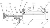
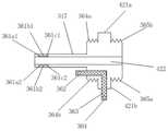
温度感应模块由温度感应外壳、温度感应右侧封口、温度感应钢芯、温度感应滑杆座、滑杆导管、滑杆、接触刷构成;在温度感应模块上,安装有分流侧接口、钢芯侧接口、铝线侧接口。The temperature sensing module is composed of a temperature sensing shell, a temperature sensing right seal, a temperature sensing steel core, a temperature sensing sliding rod seat, a sliding rod conduit, a sliding rod, and a contact brush; on the temperature sensing module, a shunt side interface and a steel core are installed. Side interface, aluminum wire side interface.
温度感应外壳、温度感应右侧封口构成感应外壳组件。温度感应钢芯、内固定点、分流侧接口、钢芯侧接口构成温度感应钢芯组件。温度感应滑杆座、滑杆导管、内嵌式接触刷短路线构成滑竿座组件。滑杆、接触刷、接触刷短路线构成接触刷组件。The temperature sensing housing and the temperature sensing right seal constitute the sensing housing assembly. The temperature-sensing steel core, the inner fixed point, the shunt side interface, and the steel-core side interface constitute the temperature-sensing steel core assembly. The temperature-sensing sliding rod seat, the sliding rod conduit, and the embedded contact brush short-circuit line constitute the sliding rod seat assembly. The sliding rod, the contact brush, and the contact brush short-circuit line constitute the contact brush assembly.
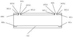
温度感应外壳为管状结构,在管状结构两端分别有左侧螺纹和右侧螺纹,左侧螺纹和右侧螺纹均为内螺纹。在温度感应外壳侧面,有钢线出口;钢线出口为温度感应外壳侧面圆孔,圆孔直径与温度感应钢芯一致。在侧面圆孔孔壁,刻有钢芯密封槽;钢芯密封槽用于放置环形密封圈,温度感应钢芯两端的外部连接段穿过钢线出口时,环形密封圈固定在钢芯密封槽,并使得温度感应钢芯两端的外部连接段与钢线出口之间保持密封;在所有部件安装后,温度感应外壳与安装在上边的部件形成密闭空间。The temperature sensing housing is a tubular structure, and the two ends of the tubular structure are respectively provided with a left thread and a right thread, and both the left thread and the right thread are internal threads. On the side of the temperature sensing housing, there is a steel wire outlet; the steel wire outlet is a round hole on the side of the temperature sensing housing, and the diameter of the round hole is the same as that of the temperature sensing steel core. A steel core sealing groove is engraved on the side wall of the circular hole; the steel core sealing groove is used to place an annular sealing ring. When the external connection sections at both ends of the temperature sensing steel core pass through the steel wire outlet, the annular sealing ring is fixed in the steel core sealing groove , and keep the seal between the external connection sections at both ends of the temperature-sensing steel core and the steel wire outlet; after all components are installed, the temperature-sensing shell and the components installed above form a closed space.
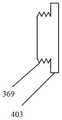
温度感应右侧封口有右侧封口螺纹和右侧底盖,右侧底盖与右侧封口螺纹为整体;右侧封口螺纹为外螺纹,与右侧螺纹紧密咬合;右侧底盖403为圆盘状,其直径大于或等于温度感应外壳的直径;温度感应右侧封口311通过右侧封口螺纹369与温度感应外壳的右侧螺纹大经相同,紧密咬合,并在右侧底盖和温度感应外壳右侧之间加入密封圈;使得温度感应右侧封口与温度感应外壳之间密封。The temperature-sensing right sealing has a right sealing thread and a right bottom cover, the right bottom cover and the right sealing thread are integral; the right sealing thread is an external thread, which is tightly engaged with the right thread; the
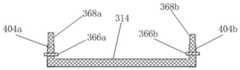
温度感应钢芯直径与使用的导线钢芯直径相同,中间段为直线,两端为外部连接段,外部连接段与中间段成90度;在两端外部连接段端头,有钢芯接口螺纹;钢芯接口螺纹为外螺纹,用于与分流侧接口、钢芯侧接口中的连接螺纹绞合;温度感应钢芯与自制热导线的内导体钢芯材质完全相同;温度感应钢芯两端的外部连接段穿过钢线出口,两端钢芯接口螺纹分别与有分流侧接口、钢芯侧接口的安装内螺纹咬合;内固定点为在外部连接段靠近中间段的一侧焊接的圆盘;内固定点圆盘半径大于钢芯半径,安装时,内固定点紧贴温度感应外壳内壁。The diameter of the temperature sensing steel core is the same as the diameter of the steel core of the conductor used. The middle section is a straight line, and the two ends are external connection sections. The outer connection section and the middle section are at 90 degrees. ;The thread of the steel core interface is an external thread, which is used for twisting with the connecting thread in the shunt side interface and the steel core side interface; the temperature sensing steel core and the inner conductor steel core of the self-made heating wire are of the same material; The external connection section passes through the steel wire outlet, and the steel core interface threads at both ends are respectively engaged with the installation internal threads with the shunt side interface and the steel core side interface; the internal fixation point is a disc welded on the side of the external connection section close to the middle section ; The radius of the inner fixed point disc is larger than the radius of the steel core. When installing, the inner fixed point is close to the inner wall of the temperature sensing shell.
分流侧接口、钢芯侧接口结构相同。分流侧接口、钢芯侧接口为短路连接接口与六角螺母焊接而成,短路连接接口与六角螺母均为金属材料制作;短路连接接口为环状;六角螺母为正六边形柱状,中间有安装内螺纹;安装内螺纹与纲芯接口螺纹匹配,紧密咬合。The structure of the shunt side interface and the steel core side interface are the same. The shunt side interface and the steel core side interface are welded by the short-circuit connection interface and the hexagonal nut. The short-circuit connection interface and the hexagonal nut are made of metal materials; the short-circuit connection interface is annular; Thread; the internal thread of the installation matches the thread of the core interface and is tightly engaged.
滑竿座组件中,温度感应滑杆座包括感应电阻连接螺纹,滑杆座本体,感应外壳连接螺纹三部分;均为为柱状。感应电阻连接螺纹,滑杆座本体,感应外壳连接螺纹同轴连接成一个整体,轴心为柱状空心体,柱状空心体的直径与滑杆导管内径相同;感应电阻连接螺纹与感应外壳连接螺纹大经相同;滑杆座本体直径大于感应外壳连接螺纹大经;感应电阻连接螺纹与感应外壳连接螺纹为外螺纹;感应外壳连接螺纹大经与左侧螺纹大经相同,感应外壳连接螺纹与左侧螺纹精密咬合,咬合时,中间加密封圈,使得二者之间密封;感应电阻连接螺纹大经与感应电阻右侧螺纹大经相同,并与感应电阻右侧螺纹紧密咬合。In the sliding rod seat assembly, the temperature sensing sliding rod seat includes three parts: the connecting thread of the sensing resistor, the body of the sliding rod seat, and the connecting thread of the sensing shell; all of which are cylindrical. The connection thread of the induction resistor, the body of the sliding rod base, and the connection thread of the induction shell are coaxially connected into a whole. The axis is a cylindrical hollow body. The diameter of the cylindrical hollow body is the same as the inner diameter of the sliding rod conduit; The diameter of the sliding rod base is larger than the diameter of the connection thread of the induction case; the connection thread of the induction resistor and the connection thread of the induction case are external threads; the connection thread of the induction case is the same as that of the left thread, and the connection thread of the induction case is The threads are precisely occluded. When occluding, a sealing ring is added in the middle to seal the two;
滑杆导管为管状结构,内径略大于滑杆的外经;滑杆导管中间的空腔与温度感应滑杆座的柱状空心体轴心相同,内径相同,成为一个整体,该整体称为伸缩滑槽;滑杆安装在伸缩滑槽中,在伸缩滑槽中滑动;滑杆导管左侧有多个导管密封槽导管密封槽中间加入密封圈,使得滑杆在滑杆导管中左右移动时,确保密封圈两端的的伸缩滑槽之间保持密封。The sliding rod conduit is a tubular structure, and the inner diameter is slightly larger than the outer diameter of the sliding rod; the cavity in the middle of the sliding rod catheter is the same as the axis of the cylindrical hollow body of the temperature sensing sliding rod seat, and the inner diameter is the same, forming a whole, which is called a telescopic sliding rod. The sliding rod is installed in the telescopic chute and slides in the telescopic chute; there are multiple pipe sealing grooves on the left side of the sliding rod guide pipe and a sealing ring is added in the middle of the pipe sealing groove, so that when the sliding rod moves left and right in the sliding rod guide pipe, ensure that Sealing is maintained between the telescopic chutes at both ends of the sealing ring.
内嵌式接触刷短路线为金属材料制作;嵌入到感应电阻连接螺纹与滑杆座本体中间。在两端有铝线侧接口和接触刷短接口;铝线侧接口在滑杆座本体侧面露出;接触刷短接口在感应电阻连接螺纹左侧底面露出。The built-in contact brush short-circuit wire is made of metal material; it is embedded between the connection thread of the inductive resistor and the body of the sliding rod seat. There are aluminum wire side interface and contact brush short interface at both ends; the aluminum wire side interface is exposed on the side of the sliding rod seat body; the contact brush short interface is exposed on the bottom surface of the left side of the inductive resistor connection thread.
感应电阻连接螺纹,滑杆座本体,感应外壳连接螺纹为一个整体,并将内嵌式接触刷短路线嵌在其中间。The connection thread of the inductive resistor, the body of the sliding rod seat, and the connection thread of the inductive shell are integrated as a whole, and the embedded contact brush short-circuit line is embedded in the middle.
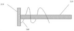
在接触刷组件中,滑杆为圆柱状,外径略小于滑杆导管中间的空腔内径,并穿过导管密封槽中间的密封圈,使得滑动时,滑杆导管内密封圈左右两边的伸缩滑槽空间保持密封。滑杆为一个整体;滑杆左侧底部有接触刷螺钉安装孔,用于与接触刷固定。In the contact brush assembly, the sliding rod is cylindrical, the outer diameter is slightly smaller than the inner diameter of the cavity in the middle of the sliding rod catheter, and passes through the sealing ring in the middle of the sealing groove of the catheter, so that when sliding, the left and right sides of the inner sealing ring of the sliding rod catheter expand and contract. The chute space remains sealed. The sliding rod is a whole; there are contact brush screw mounting holes on the bottom left side of the sliding rod for fixing with the contact brush.
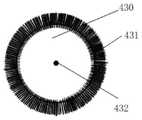
接触刷由固定圆盘和短路刷构成。固定圆盘与短路刷均为金属材料,固定圆盘为圆盘状,短路刷由大量的等长金属丝焊接在固定圆盘上,金属丝轴向过固定圆盘圆心,所有金属丝构成圆环状;固定圆盘圆心处有滑杆安装孔,用螺钉通过滑杆安装孔与接触刷螺钉安装孔,将接触刷与滑杆固定成一个整体。The contact brush consists of a fixed disc and a short-circuit brush. Both the fixed disc and the short-circuit brush are metal materials. The fixed disc is disc-shaped. The short-circuit brush is welded on the fixed disc by a large number of equal-length metal wires. The wire axis passes through the center of the fixed disc. Ring-shaped; there is a sliding rod mounting hole at the center of the fixed disc, and the contact brush and the sliding rod are fixed as a whole by screws through the sliding rod mounting hole and the contact brush screw mounting hole.
接触刷短路线为金属材料,一端焊接在固定圆盘上;一端焊接在接触刷短接口,使得短路刷与铝线侧接口短路连接;接触刷短路线环绕在滑杆上,使得滑竿左右移动时,接触刷短路线有活动区间,并保持短路刷与铝线侧接口短路连接。The short-circuit wire of the contact brush is made of metal material, and one end is welded to the fixed disc; , the contact brush short-circuit line has an active area, and the short-circuit brush and the aluminum wire side interface are kept short-circuited.
感应电阻模块由外壳底座、感应电阻丝,感应电阻外壳、均压接口构成。The inductive resistance module is composed of a shell base, an inductive resistance wire, an inductive resistance shell, and a voltage equalizing interface.
感应电阻外壳为圆筒状结构,在左右两侧,分别有感应电阻右侧螺纹与感应电阻左侧螺纹;感应电阻右侧螺纹和感应电阻左侧螺纹均为内螺纹,规格与尺寸相同。感应电阻右侧螺纹与感应电阻连接螺纹大经相同,并与感应电阻连接螺纹紧密咬合,安装时,之间加密封圈;感应电阻左侧螺纹与外壳底座安装螺纹紧密咬合,安装时,中间加密封圈;感应电组丝裸露环绕在感应电阻内壁,相邻感应电组丝有一定距离,不同圈电阻丝侧面不相接;感应电阻丝左端与均压接口短路连接;短路刷与感应电阻丝短路连接,短路刷与铝线侧接口短路连接;当滑杆左右移动时,带动短路刷左右移动;短路刷向左移动时,短路刷与均压接口之间电阻丝长度缩短,均压接口与铝线侧接口304之间电阻减少;短路刷向右移动时,短路刷与均压接口之间电阻丝长度伸长,均压接口与铝线侧接口之间电阻增加。The housing of the sensing resistor is a cylindrical structure, and on the left and right sides, there are the right thread of the sensing resistor and the left thread of the sensing resistor; the right thread of the sensing resistor and the left thread of the sensing resistor are both internal threads, and the specifications and dimensions are the same. The right thread of the inductive resistor and the connection thread of the inductive resistor have the same major diameter, and are closely engaged with the connection thread of the inductive resistor. When installing, add a sealing ring between them; the left thread of the inductive resistor is tightly engaged with the mounting thread of the housing base. Sealing ring; the induction electric group wire is exposed and surrounds the inner wall of the induction resistance, and there is a certain distance between the adjacent induction electric group wires, and the sides of the resistance wires of different circles are not connected; the left end of the induction resistance wire is short-circuited with the voltage equalizing interface; the short-circuit brush and the induction resistance wire Short-circuit connection, the short-circuit brush is short-circuited with the aluminum wire side interface; when the slider moves left and right, it drives the short-circuit brush to move left and right; when the short-circuit brush moves to the left, the length of the resistance wire between the short-circuit brush and the voltage-equalizing interface is shortened, and the voltage-equalizing interface and the The resistance between the
外壳底座分为底座支撑体和螺纹支撑体两部分,工程塑料制作,采用模压工艺模压成一个整体结构;底座支撑体和螺纹支撑体均为圆柱型,同轴,底座支撑体直径大于螺纹支撑体;螺纹支撑体外侧为外壳底座安装螺纹,外壳底座安装螺纹为外螺纹,与感应电阻左侧螺纹大径一致,且二者紧密咬合。The shell base is divided into two parts: the base support body and the threaded support body, which are made of engineering plastics and molded into an integral structure by a molding process; the base support body and the threaded support body are both cylindrical and coaxial, and the diameter of the base support body is larger than that of the threaded support body. ; The outer side of the threaded support body is the mounting thread of the housing base, and the mounting thread of the housing base is the external thread, which is the same as the large diameter of the left thread of the induction resistor, and the two are tightly engaged.
耐张塔的安装方式如下:在横担的两侧,分别安装绝缘子;在绝缘子的另一侧,安装耐张夹。假设电能从右侧向左侧输送;外导体为铝绞线,内导体为钢芯;左右两侧钢芯紧固连接在耐张夹上;右侧的钢芯与输入钢芯接头短路连接;右侧的铝绞线与输入铝线接头短路连接;左侧的钢芯与铝绞线短路后,与输出接头短路连接;地线接头与通过地线开关与地线连接。需要融冰时,地线开关闭合,使得地线接头与地线短路;不需要融冰时,地线开关打开,地线接头与地线断开。The installation method of the tension tower is as follows: insulators are installed on both sides of the cross arm; tension clamps are installed on the other side of the insulator. It is assumed that the electric energy is transmitted from the right side to the left side; the outer conductor is an aluminum stranded wire, and the inner conductor is a steel core; the steel cores on the left and right sides are tightly connected to the tension clamp; the steel core on the right side is short-circuited with the input steel core connector; The aluminum stranded wire on the right is short-circuited with the input aluminum wire connector; the steel core on the left is short-circuited with the aluminum stranded wire, and short-circuited with the output connector; the ground wire connector is connected with the ground wire through the ground switch. When ice melting is required, the ground switch is closed, so that the ground wire connector and the ground wire are short-circuited; when ice melting is not required, the ground wire switch is turned on, and the ground wire connector is disconnected from the ground wire.
单相无源防冰融冰电阻型控制设备连接的外导体外径用Dw表示;两个耐张塔之间的导线长度用L表示;内导体外经用Dn表示;自制热导线绝缘层厚度用dz表示;内导体电阻率,用An表示;额定输电电流用IA表示;额定输电电压用VA表示;设分压模块分压系数为kf,kf取值为0.7-0.95之间;所有单位均为公制单位,长度单位:米;时间单位:秒,质量单位:千克,温度单位:开尔文;The outer diameter of the outer conductor connected to the single-phase passive anti-icing and melting resistance type control equipment is represented by Dw ; the length of the wire between the two tension towers is represented by L; the outer diameter of the inner conductor is represented by Dn ; self-made heating wire insulation The layer thickness is represented by dz; the resistivity of the inner conductoris represented by An; the rated transmission current is represented by IA; the rated transmission voltage is represented by VA; All units are metric, length unit: meter; time unit: second, mass unit: kilogram, temperature unit: Kelvin;
变压器匝比:Transformer turns ratio:
分流变压器为双绕组分流变压器,或自耦分流变压器;两种变压器匝比相同;The shunt transformer is a double-winding shunt transformer, or an auto-shunt transformer; the turns ratio of the two transformers is the same;
分流变压器为升压变压器,匝比为:The shunt transformer is a step-up transformer with a turns ratio of:

感应电阻最大值:Maximum sense resistance:
感应电阻最大值为温度感应钢芯温度最低的时候的值;The maximum value of the sensing resistance is the value when the temperature of the temperature sensing steel core is the lowest;

保护电阻:Protection Resistor:

分压电阻:Voltage divider resistor:
设分压电阻取值为RFSet the voltage dividing resistor as RF

分压电容:Voltage divider capacitor:
设分流变压器的电感为LF,分压电容为CF,则:Assuming that the inductance of the shunt transformer is LF, and the voltage dividing capacitor is CF, then:

本发明的积极效果是:The positive effects of the present invention are:
1、控制设备整体重量轻,对于存量输电线,路耐张塔不需加固即可直接使用;1. The overall weight of the control equipment is light. For the existing transmission lines, the road tension tower can be used directly without reinforcement;
2、不需外加控制,便可实现输电线路自动调温;而且调温过程的传感和控制均为无源方式;2. The automatic temperature adjustment of the transmission line can be realized without external control; and the sensing and control of the temperature adjustment process are passive methods;
3、分流变压器绝缘要求低,制造成本低;3. The shunt transformer has low insulation requirements and low manufacturing cost;
4、结构简单,使用过程可靠性高。4. Simple structure and high reliability during use.
四、附图说明4. Description of the attached drawings
图1是本发明的控制设备总体结构示意图。FIG. 1 is a schematic diagram of the overall structure of the control device of the present invention.
图2是双绕组分流变压器构成的分流模块结构示意图。Figure 2 is a schematic structural diagram of a shunt module composed of a dual-winding shunt transformer.
图3是自耦分流变压器构成的分流模块结构示意图。FIG. 3 is a schematic structural diagram of a shunt module composed of an auto-shunt transformer.
图4是分压模块结构示意图。FIG. 4 is a schematic structural diagram of a voltage divider module.
图5是温控模块侧面示意图。FIG. 5 is a schematic side view of the temperature control module.
图6是温度感应模块剖面图。6 is a cross-sectional view of a temperature sensing module.
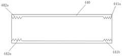
图7是温度感应外壳剖面图。FIG. 7 is a cross-sectional view of the temperature sensing housing.
图8是温度感应右侧封口示意图。Figure 8 is a schematic diagram of the temperature sensing right sealing.
图9是温度感应钢芯组件示意图。Figure 9 is a schematic diagram of a temperature sensing steel core assembly.
图10是温度感应钢芯组件中,分流侧接口与钢芯侧接口的结构示意图。分流侧接口301、钢芯侧接口302结构相同。Fig. 10 is a schematic structural diagram of the split side interface and the steel core side interface in the temperature sensing steel core assembly. The
图11是滑竿座组件剖面图示意图。Figure 11 is a schematic cross-sectional view of the slide rod seat assembly.
图12是接触刷组件示意图。Figure 12 is a schematic diagram of the contact brush assembly.
图13是接触刷结构示意图。Figure 13 is a schematic diagram of the structure of the contact brush.
图14是感应电阻模块剖面图。FIG. 14 is a cross-sectional view of an inductive resistor module.
图15是感应电阻外壳示意图。Figure 15 is a schematic diagram of the sensing resistor housing.
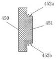
图16是外壳底座示意图。Figure 16 is a schematic diagram of the housing base.
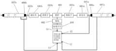
图17是耐张塔安装方式示意图。Figure 17 is a schematic diagram of the installation method of the tension tower.
图中,11输出接头,12输入铝线接头,13输入钢芯接头,14地线接头,100分压模块,101地线侧接口,102导线侧接口,200分流模块,201漏电流接口,202输出侧接口,203温控侧接口,201a双绕组漏电流接口,202a双绕组输出侧接口,203a双绕组温控侧接口,201b自耦漏电流接口,202b自耦输出侧接口,203b自耦温控侧接口,300温控模块,301分流侧接口,302钢芯侧接口,303均压接口,304铝线侧接口,310温度感应模块,311温度感应右侧封口,312温度感应外壳,314温度感应钢芯,316温度感应滑杆座,317滑杆导管,318滑杆,319接触刷,329感应电阻模块,334外壳底座,340保护电阻,350启动开关A,351启动开关B,360接触刷段路线,361导管密封槽,361a1、361a2、361b1、361b2、361c1、361c2、导管密封槽;362接触刷短接口,363内嵌式接触刷短路线,364感应电阻连接螺纹,364a、364b感应电阻连接螺纹,365感应外壳连接螺纹,365a、365b感应外壳连接螺纹,366a、366b内固定点,367a、367b钢芯密封槽,368a、368b钢芯接口螺纹,369右侧封口螺纹,367a1、367a2、367b1、367b2、367c1、367c2、367d1、367d2钢芯密封槽,400a、400b左侧螺纹;401a、401b右侧螺纹;402a、402b钢线出口,403右侧底盖,404a、404b外部连接段,405安装内螺纹,406六角螺母,407短路连接接口;421a、421b滑杆座本体;422伸缩滑槽,330a、330b感应电阻丝,440感应电阻模块外壳,441a、441b感应电阻模块右侧螺纹,442a、442b感应电阻左侧螺纹,431短路刷,452a、452b外壳底座安装螺纹。In the figure, 11 output connector, 12 input aluminum wire connector, 13 input steel core connector, 14 ground wire connector, 100 voltage divider module, 101 ground wire side interface, 102 wire side interface, 200 shunt module, 201 leakage current interface, 202 Output side interface, 203 temperature control side interface, 201a dual winding leakage current interface, 202a dual winding output side interface, 203a dual winding temperature control side interface, 201b auto leakage current interface, 202b auto coupling output side interface, 203b auto coupling temperature Control side interface, 300 temperature control module, 301 shunt side interface, 302 steel core side interface, 303 pressure equalizing interface, 304 aluminum wire side interface, 310 temperature sensing module, 311 temperature sensing right sealing, 312 temperature sensing shell, 314 temperature Sensing steel core, 316 temperature sensing sliding rod seat, 317 sliding rod conduit, 318 sliding rod, 319 contact brush, 329 sensing resistance module, 334 shell base, 340 protection resistor, 350 start switch A, 351 start switch B, 360 contact brush Section route, 361 conduit sealing groove, 361a1, 361a2, 361b1, 361b2, 361c1, 361c2, conduit sealing groove; 362 contact brush short interface, 363 embedded contact brush short circuit, 364 sensing resistor connection thread, 364a, 364b sensing resistor Connection thread, 365 induction housing connection thread, 365a, 365b induction housing connection thread, 366a, 366b internal fixing point, 367a, 367b steel core sealing groove, 368a, 368b steel core interface thread, 369 right sealing thread, 367a1, 367a2, 367b1, 367b2, 367c1, 367c2, 367d1, 367d2 steel core sealing groove, 400a, 400b left thread; 401a, 401b right thread; 402a, 402b steel wire outlet, 403 right bottom cover, 404a, 404b external connection section, 405 mounting internal thread, 406 hexagon nut, 407 short-circuit connection interface; 421a, 421b sliding rod seat body; 422 telescopic chute, 330a, 330b induction resistance wire, 440 induction resistance module shell, 441a, 441b induction resistance module right thread, 442a, 442b induction resistor left thread, 431 short-circuit brush, 452a, 452b housing base mounting thread.
五、具体实施方式Five, the specific implementation
附图给出了本发明的具体实施例。The drawings show specific embodiments of the invention.
参见附图1.See Figure 1.
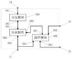
本发明用于耐张塔的单相无源防冰融冰电阻型控制设备由分压模块、分流模块、温控模块构成。对外连接接头有四个,分别为输出接头11、输入铝线接头12、输入钢芯接头13、地线接头14。The single-phase passive anti-icing and ice-melting resistance type control device for the tension tower of the present invention is composed of a voltage dividing module, a current dividing module and a temperature control module. There are four external connection joints, namely output joint 11 , input aluminum wire joint 12 , input steel core joint 13 , and
分压模块有两个接口:地线侧接口101、导线侧接口102;地线侧接口101与地线接头14短路连接,导线侧接口102与分流模块的漏电流接口201短路连接。The voltage divider module has two interfaces:
分流模块有三个接口:漏电流接口201、输出侧接口202、温控侧接口203;漏电流接口201与分压模块的导线侧接口102短路连接;输出侧接口202与输出接头11短路连接;温控侧接口203与温控模块的分流侧接口301短路连接。The shunt module has three interfaces: a leakage
温控模块有四个接口:分流侧接口301、钢芯侧接口302、均压接口303、铝线侧接口304;分流侧接口301与分流模块温控侧接口203短路连接;钢芯侧接口302与输入钢芯接头13短路连接;均压接口303与输出接头11短路连接;铝线侧接口304与输入铝线接头12短路连接。The temperature control module has four interfaces: the
参见附图2、3.See Figures 2 and 3.
分流模块有两种:双绕组分流变压器构成的分流模块和自耦分流变压器构成的分流模块。There are two types of shunt modules: shunt modules composed of double-winding shunt transformers and shunt modules composed of auto-shunt transformers.
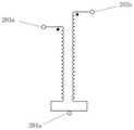
双绕组分流变压器为两个绕组的变压器结构,分别为分流低压绕组和分流高压绕组,低压绕组和高压绕组的首端为同名端;分流低压绕组线圈匝数小于分流高压绕组线圈匝数;采用双绕组分流变压器时,漏电流接口为双绕组漏电流接口201a;输出侧接口为双绕组输出侧接口202a;温控侧接口为双绕组温控侧接口203a。The double-winding shunt transformer is a transformer structure with two windings, which are the shunt low-voltage winding and the shunt high-voltage winding. In the case of a winding shunt transformer, the leakage current interface is the double winding leakage
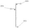
自耦分流变压器采用自耦升压变压器结构,只有一个变压器绕组,称为自耦分流绕组;分流高压首端为自耦分流绕组的首端,分流中性点为自耦分流绕组的末端;采用自耦分流变压器时,漏电流接口为自耦漏电流接口201b;输出侧接口为自耦输出侧接口202b;温控侧接口203为自耦温控侧接口203b。The auto-shunt transformer adopts the structure of an auto-step-up transformer with only one transformer winding, which is called an auto-shunt winding; the shunt high-voltage head end is the head end of the auto-shunt shunt winding, and the shunt neutral point is the end of the auto-shunt shunt winding; In the case of an auto shunt transformer, the leakage current interface is the auto leakage
参见图4.分压模块由分压电阻和分压电容并联构成;分压电阻和分压电容并联后,一端连接地线侧接口101,另一端连接导线侧接口102。See Figure 4. The voltage dividing module is composed of a voltage dividing resistor and a voltage dividing capacitor in parallel; after the voltage dividing resistor and the voltage dividing capacitor are connected in parallel, one end is connected to the
参见图5~16.See Figures 5 to 16.
温控模块由温度感应模块310、感应电阻模块329、保护电阻340、启动开关A、启动开关B构成。保护电阻340一端与均压接口303短路连接,另一端与铝线侧接口304短路连接;启动开关A 350一端与均压接口303短路连接,另一端与铝线侧接口304短路连接;启动开关B 351一端与钢芯侧接口302短路连接,另一端与铝线侧接口304短路连接。需要融冰时,启动开关A和启动开关B断开,开关A和启动开关B两端开路;不需要融冰时,启动开关A、启动开关B合上,开关A和启动开关B两端短路。The temperature control module is composed of a
本实施例中,启动开关A、启动开关B使用浙江启固电气有限公司:型号:GW9-12高压隔离开关。In this embodiment, the start switch A and the start switch B use Zhejiang Qigu Electric Co., Ltd.: Model: GW9-12 high-voltage isolation switch.
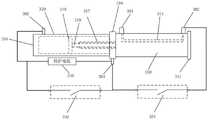
温度感应模块310由温度感应外壳312、温度感应右侧封口311、温度感应钢芯314、温度感应滑杆座316、滑杆导管317、滑杆318、接触刷319构成;在温度感应模块上,安装有分流侧接口301、钢芯侧接口302、铝线侧接口304。The
温度感应外壳312、温度感应右侧封口311构成感应外壳组件。温度感应钢芯314、内固定点366a、366b、分流侧接口301、钢芯侧接口302构成温度感应钢芯组件。温度感应滑杆座316、滑杆导管317、内嵌式接触刷短路线363构成滑竿座组件。滑杆318、接触刷319、接触刷短路线360构成接触刷组件。The
温度感应外壳312为管状结构,在管状结构两端分别有左侧螺纹400a、400b和右侧螺纹401a、401b,左侧螺纹和右侧螺纹均为内螺纹;在温度感应外壳侧面,有钢线出口402a、402b;钢线出口为温度感应外壳侧面圆孔,圆孔直径与温度感应钢芯314一致;在侧面圆孔孔壁,刻有钢芯密封槽367a1、367a2、367b1、367b2、367c1、367c2、367d1、367d2;钢芯密封槽用于放置环形密封圈,温度感应钢芯314两端的外部连接段404a、404b穿过钢线出口时,环形密封圈固定在钢芯密封槽367a、367b,并使得温度感应钢芯两端的外部连接段404a、404b与钢线出口之间保持密封;在所有部件安装后,温度感应外壳与安装在上边的部件形成密闭空间。The
温度感应右侧封口311有右侧封口螺纹369和右侧底盖403,右侧底盖与右侧封口螺纹为整体;右侧封口螺纹369为外螺纹,与右侧螺纹401a、401b紧密咬合;右侧底盖403为圆盘状,其直径大于或等于温度感应外壳312的直径;温度感应右侧封口311通过右侧封口螺纹369与温度感应外壳312的右侧螺纹401a、401b大经相同,紧密咬合,并在右侧底盖和温度感应外壳右侧之间加入密封圈;使得温度感应右侧封口与温度感应外壳之间密封。The temperature-sensing right sealing 311 has a
温度感应钢芯314直径与使用的导线钢芯直径相同,中间段为直线,两端为外部连接段404a、404b,外部连接段与中间段成90度。在两端外部连接段端头,有钢芯接口螺纹368a、368b。钢芯接口螺纹为外螺纹,用于与分流侧接口301、钢芯侧接口302中的连接螺纹绞合;温度感应钢芯314与自制热导线的内导体钢芯材质完全相同;温度感应钢芯两端的外部连接段404a、404b穿过钢线出口,两端钢芯接口螺纹分别与有分流侧接口301、钢芯侧接口302的安装内螺纹咬合;内固定点366a、366b为在外部连接段靠近中间段的一侧焊接的圆盘;内固定点圆盘半径大于钢芯半径,安装时,内固定点紧贴温度感应外壳312内壁。The diameter of the temperature
温度感应外壳与温度感应右侧封口采用力学性能好的绝缘材料制作,本实施例中,温度感应外壳与温度感应右侧封口应用模压工艺采用聚苯醚材料模压制作。The temperature sensing housing and the temperature sensing right seal are made of insulating materials with good mechanical properties. In this embodiment, the temperature sensing housing and the temperature sensing right seal are made of polyphenylene ether material using a molding process.
参见图10.分流侧接口301、钢芯侧接口302结构相同;分流侧接口301、钢芯侧接口302为短路连接接口407与六角螺母406焊接而成,短路连接接口与六角螺母均为金属材料制作;短路连接接口为环状;六角螺母为正六边形柱状,中间有安装内螺纹405;安装内螺纹405与纲芯接口螺纹368a、368b匹配,紧密咬合。See Figure 10. The
滑竿座组件中,温度感应滑杆座包括感应电阻连接螺纹364a、364b,滑杆座本体421a、421b,感应外壳连接螺纹365a、365b三部分;均为为柱状,感应电阻连接螺纹,滑杆座本体,感应外壳连接螺纹同轴连接成一个整体,轴心为柱状空心体,柱状空心体的直径与滑杆导管内径相同;感应电阻连接螺纹与感应外壳连接螺纹大经相同;滑杆座本体直径大于感应外壳连接螺纹大经;感应电阻连接螺纹与感应外壳连接螺纹为外螺纹;感应外壳连接螺纹大经与左侧螺纹400a、400b大经相同,感应外壳连接螺纹与左侧螺纹精密咬合,咬合时,中间加密封圈,使得二者之间密封;感应电阻连接螺纹大经与感应电阻右侧螺纹大经相同,并与感应电阻右侧螺纹紧密咬合。In the slide rod base assembly, the temperature sensing slide rod base includes three parts: sensing
滑杆导管317为管状结构,内径略大于滑杆318的外经。滑杆导管中间的空腔与温度感应滑杆座的柱状空心体轴心相同,内径相同,成为一个整体,该整体称为伸缩滑槽422;滑杆318安装在伸缩滑槽422中,在伸缩滑槽中滑动;滑杆导管左侧有多个导管密封槽361a1、361a2、361b1、361b2、361c1、361c2;导管密封槽中间加入密封圈,使得滑杆318在滑杆导管中左右移动时,确保密封圈两端的的伸缩滑槽之间保持密封。The sliding
内嵌式接触刷短路线363为金属材料制作;嵌入到感应电阻连接螺纹364a、364b与滑杆座本体421a、421b中间;在两端有铝线侧接口304和接触刷短接口362;铝线侧接口304在滑杆座本体421a、421b侧面露出;接触刷短接口362在感应电阻连接螺纹左侧底面露出。感应电阻连接螺纹364a、364b,滑杆座本体421a、421b,感应外壳连接螺纹365a、365b用工程塑料制作,实施例采用聚苯醚,采用模压工艺模压成为一个整体,并将内嵌式接触刷短路线363嵌在其中间。The embedded contact brush short-
附图12给出的接触刷组件示意图中,滑杆318为圆柱状,外径略小于滑杆导管317内径,并穿过导管密封槽361a1、361a2、361b1、361b2、361c1、361c2中间的密封圈,使得滑动时,滑杆导管内密封圈左右两边的伸缩滑槽422空间保持密封;滑杆318为一个整体;滑杆左侧底部有接触刷螺钉安装孔,用于与接触刷319固定。In the schematic diagram of the contact brush assembly shown in FIG. 12, the sliding
接触刷319由固定圆盘430和短路刷431构成;固定圆盘与短路刷均为金属材料,固定圆盘为圆盘状,短路刷431由大量的等长金属丝焊接在固定圆盘上,金属丝轴向过固定圆盘圆心,所有金属丝构成圆环状;固定圆盘圆心处有滑杆安装孔432,用螺钉通过滑杆安装孔与接触刷螺钉安装孔,将接触刷319与滑杆318固定成一个整体。The
接触刷短路线360,为金属材料,一端焊接在固定圆盘430上;一端焊接在接触刷短接口362,使得短路刷与铝线侧接口304短路连接;接触刷短路线360环绕在滑杆318上,使得滑竿左右移动时,接触刷短路线有活动区间,并保持短路刷431与铝线侧接口304短路连接。The contact brush short-
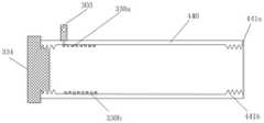
见附图14-16。感应电阻模块329由外壳底座334、感应电阻丝330a、330b,感应电阻外壳440、均压接口303构成。See Figures 14-16. The
感应电阻外壳440为圆筒状结构,在左右两侧,分别有感应电阻右侧螺纹441a、441b与感应电阻左侧螺纹442a、442b;感应电阻右侧螺纹和感应电阻左侧螺纹均为内螺纹,规格与尺寸相同;感应电阻右侧螺纹与感应电阻连接螺纹364a、364b大经相同,并与感应电阻连接螺纹紧密咬合,安装时,之间加密封圈;感应电阻左侧螺纹与外壳底座安装螺纹452a、452b紧密咬合,安装时,中间加密封圈;感应电组丝330a、330b裸露环绕在感应电阻内壁,相邻感应电组丝有一定距离,不同圈电阻丝侧面不相接;感应电阻丝左端与均压接口303短路连接;短路刷431与感应电阻丝短路连接,短路刷与铝线侧接口304短路连接;当滑杆318左右移动时,带动短路刷431左右移动;短路刷向左移动时,短路刷与均压接口303之间电阻丝长度缩短,均压接口303与铝线侧接口304之间电阻减少;短路刷向右移动时,短路刷431与均压接口303之间电阻丝长度伸长,均压接口303与铝线侧接口304之间电阻增加。The
当温度感应钢芯温度升高时,会将温度感应外壳内的油温升高,油温升高后体积膨胀,推动滑杆向左移动,使得均压接口303与铝线侧接口304之间电阻减少,并使得温度感应钢芯电流减少,温度感应钢芯温度降低。当温度感应钢芯温度降低时,会将温度感应外壳内的油温降低,油温降低后体积收缩,推动滑杆向右移动,使得均压接口303与铝线侧接口304之间电阻增加,并使得温度感应钢芯电流增加,温度感应钢芯温度增加。When the temperature of the temperature-sensing steel core rises, the temperature of the oil in the temperature-sensing housing will rise, and the volume of the oil will expand after the rising temperature, pushing the sliding rod to move to the left, so that the pressure-equalizing
外壳底座334分为底座支撑体450和螺纹支撑体451两部分,由工程塑料制作,实施例采用聚苯醚,采用模压工艺模压成一个整体结构;底座支撑体和螺纹支撑体均为圆柱型,同轴,底座支撑体直径大于螺纹支撑体;螺纹支撑体外侧为外壳底座安装螺纹452a、452b,外壳底座安装螺纹为外螺纹,与感应电阻左侧螺纹大径一致,且二者紧密咬合。The
参见附图17。See Figure 17.
本实施例采用的输电导线为“CN201810370549.8”公示的自制热导体,外导体为铝绞线607a、607b,内导体为钢芯605a、605b。The power transmission wires used in this embodiment are self-made heat conductors disclosed in "CN201810370549.8", the outer conductors are aluminum stranded
耐张塔的安装方式如下:在横担601两侧,分别安装绝缘子603a、603b;在绝缘子的另一侧,安装耐张夹604a、604b。The installation method of the tension tower is as follows: on both sides of the
假设电能从右侧向左侧输送;左右两侧钢芯紧固连接在耐张夹上;右侧的钢芯与输入钢芯接头13短路连接;右侧的铝绞线与输入铝线接头12短路连接;左侧的钢芯与铝绞线短路后,与输出接头11短路连接;地线接头14与通过地线开关608与地线连接。It is assumed that the electric energy is transmitted from the right side to the left side; the steel cores on the left and right sides are tightly connected to the tension clamp; the steel core on the right side is short-circuited with the input
需要融冰时,地线开关608闭合,使得地线接头与地线短路;不需要融冰时,地线开关打开,地线接头与地线断开。地线开关采用浙江启固电气有限公司:型号:GW9-12高压隔离开关。When ice melting is required, the
本实施例的设计参数计算方法:外导体外径,用Dw表示;两个安装有本发明装置耐张塔之间自制热导线长度,用L表示;内导体外经,用Dn表示;自制热导线绝缘层厚度,用dz表示;内导体电阻率,用An表示;额定输电电流,用IA表示;额定输电电压:用VA表示;设分压模块分压系数为kf,kf取值为0.7-0.95之间。The calculation method of the design parameters of this embodiment: the outer diameter of the outer conductor is represented byDw ; the length of the self-made heating wire between two tension towers installed with the device of the present invention is represented by L; the outer diameter of the inner conductor is represented byDn ; The thickness of the insulation layer of the self-made heating wire is represented by dz; the resistivity of the inner conductor is represented by An ; the rated transmission current is represented by IA; the rated transmission voltage is represented by VA; between 0.7-0.95.
所有单位均为公制单位:长度单位:米(m);时间单位:秒(sec)。质量单位:千克(kg)。温度单位:开尔文(K)。All units are metric: length unit: meter (m); time unit: second (sec). Mass unit: kilogram (kg). Temperature unit: Kelvin (K).
变压器匝比:Transformer turns ratio:
分流变压器为双绕组分流变压器,或自耦分流变压器;两种变压器匝比相同;The shunt transformer is a double-winding shunt transformer, or an auto-shunt transformer; the turns ratio of the two transformers is the same;
分流变压器为升压变压器,匝比为:The shunt transformer is a step-up transformer with a turns ratio of:

感应电阻最大值:Maximum sense resistance:
感应电阻最大值为温度感应钢芯温度最低的时候的值;The maximum value of the sensing resistance is the value when the temperature of the temperature sensing steel core is the lowest;

保护电阻:Protection Resistor:

分压电阻:Voltage divider resistor:
设分压电阻取值为RFSet the voltage dividing resistor as RF

分压电容:Voltage divider capacitor:
设分流变压器的电感为LF,分压电容为CF,则:Assuming that the inductance of the shunt transformer is LF, and the voltage dividing capacitor is CF, then:

Claims (7)
Translated fromChinese


Priority Applications (1)
| Application Number | Priority Date | Filing Date | Title |
|---|---|---|---|
| CN202110797159.0ACN113507082B (en) | 2021-07-14 | 2021-07-14 | A single-phase passive anti-icing and melting ice resistance control device for tension towers |
Applications Claiming Priority (1)
| Application Number | Priority Date | Filing Date | Title |
|---|---|---|---|
| CN202110797159.0ACN113507082B (en) | 2021-07-14 | 2021-07-14 | A single-phase passive anti-icing and melting ice resistance control device for tension towers |
Publications (2)
| Publication Number | Publication Date |
|---|---|
| CN113507082A CN113507082A (en) | 2021-10-15 |
| CN113507082Btrue CN113507082B (en) | 2022-05-13 |
Family
ID=78013380
Family Applications (1)
| Application Number | Title | Priority Date | Filing Date |
|---|---|---|---|
| CN202110797159.0AExpired - Fee RelatedCN113507082B (en) | 2021-07-14 | 2021-07-14 | A single-phase passive anti-icing and melting ice resistance control device for tension towers |
Country Status (1)
| Country | Link |
|---|---|
| CN (1) | CN113507082B (en) |
Citations (13)
| Publication number | Priority date | Publication date | Assignee | Title |
|---|---|---|---|---|
| US6396172B1 (en)* | 1998-12-04 | 2002-05-28 | Hydro-Quebec | Switching apparatus and method for a segment of an electric power line |
| US7000478B1 (en)* | 2005-01-31 | 2006-02-21 | Texas Instruments Incorporated | Combined pressure and temperature transducer |
| JP4567806B1 (en)* | 2010-01-08 | 2010-10-20 | 立山科学工業株式会社 | Non-contact temperature sensor |
| UA84934U (en)* | 2013-03-27 | 2013-11-11 | Таврийский Государственный Агротехнологический Университет | Signaling and melting system for glazed frost on wires of overhead transmission line |
| CN206225052U (en)* | 2016-09-30 | 2017-06-06 | 四川大学 | It is a kind of from ice melting electric cable and its ice-melting device |
| CN208298041U (en)* | 2018-02-07 | 2018-12-28 | Tcl-罗格朗国际电工(惠州)有限公司 | Incude temperature control circuit |
| CN208333516U (en)* | 2018-07-17 | 2019-01-04 | 湖北惠祥电子科技有限公司 | A kind of automobile sensor shell |
| CN109211434A (en)* | 2018-07-04 | 2019-01-15 | 中国船舶重工集团公司第七〇九研究所 | A kind of quickly dismantled passive and wireless induction takes temperature measurement sensor |
| CN109361187A (en)* | 2018-12-06 | 2019-02-19 | 四川大学 | Lossless single-phase shunt between lines and its design and control method |
| CN209298846U (en)* | 2018-12-06 | 2019-08-23 | 四川大学 | Line-to-line lossless three-phase shunt |
| CN110676790A (en)* | 2019-11-08 | 2020-01-10 | 四川大学 | Passive intelligent ice melting control equipment and ice melting control method thereof |
| CN111009869A (en)* | 2019-11-25 | 2020-04-14 | 国网湖南省电力有限公司 | Real-time online ice melting equipment for transmission conductor and control method thereof |
| CN211239259U (en)* | 2019-11-08 | 2020-08-11 | 四川大学 | Passive intelligent ice melting control equipment |
Family Cites Families (1)
| Publication number | Priority date | Publication date | Assignee | Title |
|---|---|---|---|---|
| US20100243633A1 (en)* | 2009-03-24 | 2010-09-30 | Tung Huynh | Power Line De-Icing Apparatus |
- 2021
- 2021-07-14CNCN202110797159.0Apatent/CN113507082B/ennot_activeExpired - Fee Related
Patent Citations (13)
| Publication number | Priority date | Publication date | Assignee | Title |
|---|---|---|---|---|
| US6396172B1 (en)* | 1998-12-04 | 2002-05-28 | Hydro-Quebec | Switching apparatus and method for a segment of an electric power line |
| US7000478B1 (en)* | 2005-01-31 | 2006-02-21 | Texas Instruments Incorporated | Combined pressure and temperature transducer |
| JP4567806B1 (en)* | 2010-01-08 | 2010-10-20 | 立山科学工業株式会社 | Non-contact temperature sensor |
| UA84934U (en)* | 2013-03-27 | 2013-11-11 | Таврийский Государственный Агротехнологический Университет | Signaling and melting system for glazed frost on wires of overhead transmission line |
| CN206225052U (en)* | 2016-09-30 | 2017-06-06 | 四川大学 | It is a kind of from ice melting electric cable and its ice-melting device |
| CN208298041U (en)* | 2018-02-07 | 2018-12-28 | Tcl-罗格朗国际电工(惠州)有限公司 | Incude temperature control circuit |
| CN109211434A (en)* | 2018-07-04 | 2019-01-15 | 中国船舶重工集团公司第七〇九研究所 | A kind of quickly dismantled passive and wireless induction takes temperature measurement sensor |
| CN208333516U (en)* | 2018-07-17 | 2019-01-04 | 湖北惠祥电子科技有限公司 | A kind of automobile sensor shell |
| CN109361187A (en)* | 2018-12-06 | 2019-02-19 | 四川大学 | Lossless single-phase shunt between lines and its design and control method |
| CN209298846U (en)* | 2018-12-06 | 2019-08-23 | 四川大学 | Line-to-line lossless three-phase shunt |
| CN110676790A (en)* | 2019-11-08 | 2020-01-10 | 四川大学 | Passive intelligent ice melting control equipment and ice melting control method thereof |
| CN211239259U (en)* | 2019-11-08 | 2020-08-11 | 四川大学 | Passive intelligent ice melting control equipment |
| CN111009869A (en)* | 2019-11-25 | 2020-04-14 | 国网湖南省电力有限公司 | Real-time online ice melting equipment for transmission conductor and control method thereof |
Non-Patent Citations (1)
| Title |
|---|
| 基于自融冰导线的在线实时融冰技术初探;莫思特等;《科学技术与工程》;20181128(第33期);第64-70页* |
Also Published As
| Publication number | Publication date |
|---|---|
| CN113507082A (en) | 2021-10-15 |
Similar Documents
| Publication | Publication Date | Title |
|---|---|---|
| CN102568696B (en) | High voltage insulation current lead for superconductive electric device | |
| CN110676790B (en) | Passive intelligent ice melting control equipment and ice melting control method thereof | |
| CN109361187B (en) | Lossless single-phase shunt between lines and its design and control method | |
| CN1971778B (en) | Single-phase self-coupling on-load voltage-regulating transformer | |
| CN109449854B (en) | Station-used lossless three-phase current divider for preventing ice and melting ice and design and control method | |
| CN113507082B (en) | A single-phase passive anti-icing and melting ice resistance control device for tension towers | |
| CN113507081B (en) | Passive lossless single-phase anti-icing and de-icing control equipment for strain tower | |
| CN209046216U (en) | The lossless single-phase current divider in station for anti-icing ice-melt | |
| CN113507084B (en) | Single-phase resistance type passive anti-icing and de-icing control equipment for strain tower | |
| CN109361186B (en) | Station nondestructive single-phase shunt and design and control method for anti-icing and melting | |
| CN114999782B (en) | Phase-shifting transformer for loop closing transfer power supply | |
| CN206433205U (en) | A self-melting ice conductor and its ice-melting equipment | |
| CN101916632B (en) | A high-power water-cooled resistor for a high-voltage direct current transmission converter valve | |
| CN209298845U (en) | Lossless single-phase shunt between lines | |
| CN113078603A (en) | Ice melting device for power line | |
| CN113507085B (en) | A three-phase passive anti-icing and melting ice resistance control device | |
| CN113507083B (en) | A three-phase passive anti-icing and ice-melting resistance control device for tension towers | |
| CN113517667B (en) | Nondestructive single-phase anti-icing and de-icing control equipment based on insulated gate bipolar transistor | |
| CN108183014A (en) | A kind of voltage transformer | |
| CN109347041A (en) | Lossless three-phase current shunt between lines and its design and control method | |
| CN209658875U (en) | A kind of high-tension cable and deicing system | |
| CN208175017U (en) | It is embedded in the heating equipment of the self-control heat conductor of insulating heat-conduction material | |
| CN113541081B (en) | Lossless single-phase anti-icing and de-icing control equipment based on thyristor | |
| CN216849378U (en) | Hybrid transmission cable, charging circuit, charging gun head and testing tool | |
| CN113507086B (en) | Passive lossless three-phase anti-icing and de-icing control equipment for strain tower |
Legal Events
| Date | Code | Title | Description |
|---|---|---|---|
| PB01 | Publication | ||
| PB01 | Publication | ||
| SE01 | Entry into force of request for substantive examination | ||
| SE01 | Entry into force of request for substantive examination | ||
| GR01 | Patent grant | ||
| GR01 | Patent grant | ||
| CF01 | Termination of patent right due to non-payment of annual fee | ||
| CF01 | Termination of patent right due to non-payment of annual fee | Granted publication date:20220513 |