CN113496053B - Intelligent layout method for bidirectional bottom ribs of multi-opening prefabricated laminated slab - Google Patents
Intelligent layout method for bidirectional bottom ribs of multi-opening prefabricated laminated slabDownload PDFInfo
- Publication number
- CN113496053B CN113496053BCN202110556394.9ACN202110556394ACN113496053BCN 113496053 BCN113496053 BCN 113496053BCN 202110556394 ACN202110556394 ACN 202110556394ACN 113496053 BCN113496053 BCN 113496053B
- Authority
- CN
- China
- Prior art keywords
- short
- steel bar
- reinforcing steel
- opening
- reinforcement
- Prior art date
- Legal status (The legal status is an assumption and is not a legal conclusion. Google has not performed a legal analysis and makes no representation as to the accuracy of the status listed.)
- Active
Links
Images


Classifications
- G—PHYSICS
- G06—COMPUTING OR CALCULATING; COUNTING
- G06F—ELECTRIC DIGITAL DATA PROCESSING
- G06F30/00—Computer-aided design [CAD]
- G06F30/10—Geometric CAD
- G06F30/13—Architectural design, e.g. computer-aided architectural design [CAAD] related to design of buildings, bridges, landscapes, production plants or roads
- G—PHYSICS
- G06—COMPUTING OR CALCULATING; COUNTING
- G06F—ELECTRIC DIGITAL DATA PROCESSING
- G06F30/00—Computer-aided design [CAD]
- G06F30/20—Design optimisation, verification or simulation
- G—PHYSICS
- G06—COMPUTING OR CALCULATING; COUNTING
- G06F—ELECTRIC DIGITAL DATA PROCESSING
- G06F2111/00—Details relating to CAD techniques
- G06F2111/10—Numerical modelling
Landscapes
- Engineering & Computer Science (AREA)
- Physics & Mathematics (AREA)
- Geometry (AREA)
- Theoretical Computer Science (AREA)
- General Physics & Mathematics (AREA)
- Computer Hardware Design (AREA)
- Evolutionary Computation (AREA)
- General Engineering & Computer Science (AREA)
- Structural Engineering (AREA)
- Computational Mathematics (AREA)
- Civil Engineering (AREA)
- Mathematical Analysis (AREA)
- Mathematical Optimization (AREA)
- Pure & Applied Mathematics (AREA)
- Architecture (AREA)
- Reinforcement Elements For Buildings (AREA)
Abstract
Translated fromChinese
Description
Translated fromChinese技术领域technical field
本发明涉及一种建筑施工技术领域,特别是一种基于BIM技术,对BIM三维模型多洞口的预制叠合板中的底筋的空间位置进行参数化设置,使钢筋实体模型的高精度布置的方法。The invention relates to the technical field of building construction, in particular to a method based on the BIM technology to parameterize the spatial position of the bottom reinforcement in the multi-hole prefabricated laminated board of the BIM three-dimensional model, so as to make the high-precision arrangement of the reinforcement solid model .
背景技术Background technique
建筑信息模型(Building Information Modeling)是以建筑工程项目的各项相关信息数据作为模型的基础,进行建筑模型的建立,通过数字信息仿真模拟建筑物所具有的真实信息。它具有可视化,协调性,模拟性,优化性和可出图性五大特点。Building Information Modeling (Building Information Modeling) takes the relevant information data of the construction project as the basis of the model, establishes the building model, and simulates the real information of the building through digital information simulation. It has five characteristics of visualization, coordination, simulation, optimization and drawing.
预制叠合板具有整体性能良好,连续性和整体刚度大的特点。高精度底筋布置的预制叠合板有利于钢筋的下料,对现场钢筋绑扎过程中的钢筋绑扎顺序,特别是在预留洞口处的绑扎位置有很好的技术指导作用。在预留洞口处的钢筋布置过程中,往往会出现钢筋与洞口碰撞,不仅无法正确表达图纸信息,同时使得洞口处的强度达不到设计要求。The prefabricated laminated board has the characteristics of good overall performance, continuity and overall stiffness. The prefabricated laminate with high-precision bottom reinforcement arrangement is conducive to the cutting of steel bars, and has a good technical guidance for the binding sequence of steel bars during the on-site steel bar binding process, especially the binding positions at the reserved openings. In the process of arranging the steel bars at the reserved openings, there are often collisions between the steel bars and the openings, which not only fails to express the drawing information correctly, but also makes the strength of the openings fail to meet the design requirements.
目前对于多洞口叠合板内部钢筋的深化设计仅仅停留在视觉效果阶段。例如Autodesk公司的Revit系列软件,可以采用手动对钢筋进行布置,但是操作复杂,且碰撞问题严重。目前市面上的其他对于叠合板内部钢筋能快速布置的插件,布置规则混乱,可调参数较少。同时在操作方面,面对预留洞口位置不同的叠合板,利用Revit系列软件,建模人员无法通过复制已经手工布置的底筋到其他不同预留位置的洞口处,全部采用手工建模需要消耗大量人力物力,且无法达到二维图纸所需要的精确度。At present, the detailed design of the internal reinforcement of the multi-hole laminated slab is only at the stage of visual effects. For example, Autodesk's Revit series software can manually arrange reinforcement, but the operation is complicated and the collision problem is serious. At present, other plug-ins on the market that can quickly arrange the reinforcement inside the laminated board, the arrangement rules are chaotic, and there are few adjustable parameters. At the same time, in terms of operation, in the face of laminated slabs with different reserved opening positions, using Revit series software, the modeler cannot copy the bottom ribs that have been manually arranged to other openings in different reserved positions. All manual modeling requires consumption of A lot of manpower and material resources, and the accuracy required for 2D drawings cannot be achieved.
发明内容SUMMARY OF THE INVENTION
本发明的目的是提供一种多洞口的预制叠合板双向底筋智能化布设方法,要解决现有BIM技术深化设计过程中,效率低下费时费工的技术问题。The purpose of the present invention is to provide a multi-hole prefabricated laminated board two-way intelligent layout method, to solve the technical problem of low efficiency, time-consuming and labor-intensive in the process of deepening the design of the existing BIM technology.
为实现上述目的,本发明采用如下技术方案:To achieve the above object, the present invention adopts the following technical solutions:
一种多洞口的预制叠合板双向底筋智能化布设方法,包括以下步骤:A method for intelligently laying bidirectional bottom ribs of a multi-hole prefabricated laminated board, comprising the following steps:
步骤一:选中已经布置有洞口的预制叠合板混凝土模型,同时得到该模型的 ID。Step 1: Select the prefabricated composite slab concrete model that has been arranged with openings, and get the ID of the model at the same time.
步骤二:获取步骤一中叠合板表面的基本参数。Step 2: Obtain the basic parameters of the surface of the laminated board in Step 1.
步骤三:筛选得到叠合板下表面的四条外边,将下表面的边按其长度进行从小到大排序,并进行两两分组。Step 3: Filter out the four outer edges of the lower surface of the laminated board, sort the edges of the lower surface from small to large according to their lengths, and group them into pairs.
步骤四:将步骤三中已分组完成的叠合板长边方向两边的起点和终点相连,得到短向钢筋的初始定位线,并且将初始定位线向两边方向延长,再将延长后的短向钢筋初始定位线根据偏移长度列表进行偏移,得到短向钢筋定位线。同理,得到长向钢筋定位线。Step 4: Connect the start and end points on both sides of the long-side direction of the laminated board that have been grouped in step 3 to obtain the initial positioning line of the short-direction reinforcement, and extend the initial positioning line to both sides, and then extend the short-direction reinforcement. The initial positioning line is offset according to the offset length list to obtain the short-direction reinforcement positioning line. In the same way, the long-direction reinforcement positioning line is obtained.
步骤五:根据步骤二获取叠合板混凝土模型洞口半径与圆心数据。Step 5: According to Step 2, obtain the data of the radius and center of the opening of the composite slab concrete model.
步骤六:根据步骤四和步骤五获取的长向钢筋定位线和洞口数据,判断洞口是否与长向钢筋定位线相交,若两者相交,将洞口圆心分别沿着短向钢筋定位线所在的两个方向偏移对应洞口半径+10的距离,得到长向钢筋定位线的两个顶点。再获取与长边方向相交的洞口所在的短边方向的顶点,交点,以及圆心到长边顶点的距离。同理,得到与短向钢筋相交的洞口所在的长边方向顶点、交点与圆心,以及圆心到短边顶点的距离。Step 6: According to the long-direction reinforcement positioning line and the opening data obtained in Steps 4 and 5, determine whether the opening intersects with the long-direction reinforcement positioning line. The offset in each direction corresponds to the distance of the radius of the opening +10, and the two vertices of the long-direction reinforcement positioning line are obtained. Then obtain the vertex in the short side direction where the opening intersecting with the long side direction is located, the intersection point, and the distance from the center of the circle to the vertex of the long side. In the same way, the vertex in the long side direction, the intersection point and the center of the circle, and the distance from the center of the circle to the vertex of the short side are obtained.
步骤七:根据步骤六中短向钢筋定位线与洞口交点的断线,取短向钢筋洞口断线的中点,判断断线中点到一侧顶点的距离是否大于对应圆心洞口的半径,若断线中点到一侧顶点的距离大于对应圆心洞口的半径,获取短向钢筋与洞口的交点更近的一侧点位,否则获取短向钢筋与洞口的交点更远的一侧点位,由此判断规则得到短向钢筋弯绕点位,同理得到长向钢筋弯绕点位。Step 7: According to the broken line between the short-direction reinforcing bar positioning line and the intersection point of the hole in step 6, take the midpoint of the short-direction steel bar hole broken line, and determine whether the distance from the broken line midpoint to one side vertex is greater than the radius of the corresponding hole in the center of the circle. The distance from the midpoint of the broken line to the vertex on one side is greater than the radius of the corresponding hole in the center of the circle, and the point on the side that is closer to the intersection of the short-direction steel bar and the hole is obtained, otherwise, the point on the side that is farther from the intersection of the short-direction steel bar and the hole is obtained. From this judgment rule, the short-direction steel bar bending point is obtained, and the long-direction steel bar bending point is obtained in the same way.
步骤八:由步骤一到步骤七所获取的钢筋定位线,输入钢筋的基本参数,生成钢筋的实体模型。Step 8: Input the basic parameters of the reinforcement bar from the reinforcement positioning line obtained in the step 1 to the step 7, and generate the solid model of the reinforcement bar.
与现有技术相比本发明具有以下特点和有益效果:Compared with the prior art, the present invention has the following features and beneficial effects:
本发明是在主流BIM软件Revit的可视化编程插件Dynamo上操作,通过计算机编程,智能地计算分析数据并判断返回结果,可以快速实现叠合板钢筋的自动化布置。The invention is operated on Dynamo, a visual programming plug-in of mainstream BIM software Revit, through computer programming, intelligently calculates and analyzes data and judges the returned result, and can quickly realize the automatic arrangement of the reinforcement of the superimposed plate.
本发明相较于已有的底面钢筋布置方法,利用编程节点对底面钢筋的点位进行自动布置,采用钢筋自动生成的方式,实现统计叠合板底筋数量,更贴近实际生产与统计的需求。Compared with the existing bottom reinforcement arrangement method, the present invention utilizes programming nodes to automatically arrange the bottom reinforcement points, adopts the method of automatic generation of reinforcement, realizes the counting of the bottom reinforcements of the superimposed slab, and is closer to the actual production and statistical requirements.
本发明对参考图纸中的洞口与钢筋的碰撞形式,实现以下多种碰撞情况:同时碰撞一根钢筋、同时碰撞两根钢筋、同时都不碰撞钢筋、以上三种情况同时随机存在。The present invention realizes the following multiple collision situations for the collision form of the opening and the steel bar in the reference drawing: simultaneously colliding with one steel bar, simultaneously colliding with two steel bars, not colliding with the steel bar at the same time, and the above three situations exist randomly at the same time.
本发明还根据参考图纸布筋要求与建模人员的建模习惯,对底筋进行精确的参数设置,包括起步钢筋距长边的距离、钢筋间距、钢筋距板底部距离、钢筋直径、出筋长度。同时满足叠合板板的出筋要求,提高了程序操作的效率。The present invention also sets precise parameters for the bottom reinforcement according to the reference drawing requirements for reinforcement arrangement and the modeling habits of the modeling personnel, including the distance between the starting reinforcement bar and the long side, the reinforcement bar spacing, the reinforcement bar distance from the bottom of the plate, the reinforcement bar diameter, and the reinforcement reinforcement. length. At the same time, it can meet the requirements of the rib of the laminated plate, and improve the efficiency of the program operation.
附图说明Description of drawings
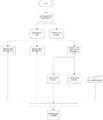
图1是本发明的总流程图。Figure 1 is a general flow diagram of the present invention.
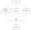
图2是获取板基本参数流程图。Figure 2 is a flow chart of acquiring the basic parameters of the board.
图3是获取洞口参数流程图。Figure 3 is a flow chart of obtaining the parameters of the opening.
图4是获取短向钢筋定位线流程图。Figure 4 is a flow chart of obtaining short-direction reinforcing bar positioning lines.
图5是获取长向钢筋定位线流程图。Fig. 5 is a flow chart of obtaining long-direction reinforcement positioning lines.
图6是获取长短向钢筋与洞口相交的圆顶点与交点流程图。FIG. 6 is a flow chart of obtaining the circle vertex and intersection point of the intersection of the long and short direction steel bars and the opening.
图7是获取短向钢筋弯绕点位流程图。Figure 7 is a flow chart of obtaining the bending point of the short-direction steel bar.
图8是获取长向钢筋弯绕点位流程图。Figure 8 is a flow chart of obtaining the bending point of the long-direction steel bar.
图9是钢筋底筋实体模型流程图。Fig. 9 is the flow chart of the solid model of the reinforcement bottom bar.
具体实施方式Detailed ways
实施过程中的模型是利用Autodesk公司发布的BIM建模平台Revit软件进行建造。The model in the implementation process is built using Revit software, the BIM modeling platform released by Autodesk.
上述发明内容可以通过计算机编程语言实现,在Dynamo的环境下使用DesignScript语言进行编程,施工步骤如下:The above-mentioned content of the invention can be realized by computer programming language, and the DesignScript language is used for programming under the environment of Dynamo. The construction steps are as follows:
步骤一:建立已经布置有洞口的预制叠合板混凝土模型。Step 1: Build a prefabricated composite slab concrete model with openings arranged.
1.叠合板模型洞口位置要随机布置,洞口大小和数量也随机设置。1. The position of the openings of the laminated plate model should be randomly arranged, and the size and number of the openings should also be randomly set.
步骤二:获取叠合板基本参数。Step 2: Obtain the basic parameters of the laminated board.
1.利用SelectModelElement节点选择需要布置的预制叠合板混凝土模型。1. Use the SelectModelElement node to select the precast composite slab concrete model to be arranged.
2.根据选择的模型,获取其表面参数和表面积参数。2. According to the selected model, obtain its surface parameters and surface area parameters.
步骤三:筛选得到叠合板下表面的四条外边。Step 3: The four outer edges of the lower surface of the laminated board are obtained by screening.
1.利用SortIndexByValue节点将步骤二中的叠合板表面积进行从小到大排序。1. Use the SortIndexByValue node to sort the surface area of the laminated board in step 2 from small to large.
2.将排序后的所有表面以两个表面为一组进行分组,取分组后表面积最大的两个表面,即叠合板的上下表面。2. Group all the sorted surfaces as a group of two surfaces, and take the two surfaces with the largest surface area after grouping, that is, the upper and lower surfaces of the superimposed board.
3.利用transpose节点将叠合板上下表面边的列表进行转置。3. Use the transpose node to transpose the list of upper and lower surface edges on the laminated board.
4.分别取上下表面一条边的两个起点,获取两个起点的Z轴方向的坐标,根据Z轴方向坐标的数值进行从小到大排序。4. Take the two starting points of one edge on the upper and lower surfaces respectively, obtain the coordinates of the two starting points in the Z-axis direction, and sort them from small to large according to the values of the Z-axis coordinates.
5.利用GetItemAtIndex节点根据Z轴坐标的排序再对上下两个表面进行排序。5. Use the GetItemAtIndex node to sort the upper and lower surfaces according to the order of the Z-axis coordinates.
6.根据上下表面排序后的列表,获取下表面的所有边,将所有的边根据其长度从大到小排序。由于普通洞口处的圆的周长小于外边长,将排序后的边两两分组。6. According to the sorted list of the upper and lower surfaces, get all the edges of the lower surface, and sort all the edges according to their lengths from large to small. Since the perimeter of the circle at the common hole is smaller than the outer edge, the sorted edges are grouped into two groups.
7.得到底面长边和底面短边。7. Get the bottom long side and bottom short side.
步骤四:得到预制叠合板短边方向的钢筋定位线Step 4: Obtain the reinforcement positioning line in the direction of the short side of the prefabricated laminated board
1.根据叠合板底面的两条长边,分别取叠合板两条底面长边的的起点和终点,将两点相连,得到短向钢筋的底面初始定位线。1. According to the two long sides of the bottom surface of the laminated board, take the starting point and the end point of the two long sides of the bottom surface of the laminated board respectively, and connect the two points to obtain the initial positioning line of the bottom surface of the short-direction steel bar.
2.利用Curve.ExtendEnd节点分别将短向钢筋的初始定位线向其起点方向与终点方向进行延长,延长长度即为出筋长度。2. Use the Curve.ExtendEnd node to extend the initial positioning line of the short-direction steel bar to its starting point and end point respectively, and the extended length is the length of the rib.
3.设置起步筋距离与钢筋间距的可调参数,并获得底面长边的长度,得到短向钢筋首根钢筋偏移长度的长度列表。3. Set the adjustable parameters of the distance of the starting bar and the spacing of the reinforcing bars, and obtain the length of the long side of the bottom surface, and obtain the length list of the offset length of the first reinforcing bar in the short direction.
4.利用Geometry.Translate节点将延伸后的短边方向初始定位线根据偏移距离长度列表进行偏移,得到短向底筋的定位线。同理,得到预制叠合板长向钢筋的定位线。4. Use the Geometry.Translate node to offset the extended initial positioning line in the short side direction according to the offset distance length list to obtain the positioning line of the short bottom rib. In the same way, the positioning line of the length of the prefabricated laminated board to the steel bar is obtained.
步骤五:获取预制叠合板的洞口与圆心数据Step 5: Obtain the hole and center data of the prefabricated laminate
1.利用DropItems节点删去步骤三中叠合板下表面的一组长边与一组短边,得到叠合板所有的洞口的边。1. Use the DropItems node to delete a set of long sides and a set of short sides on the lower surface of the laminated board in step 3 to obtain the edges of all the openings of the laminated board.
2.利用Curve.PointsAtEqualSegmentLength节点得到洞口上的三个点。2. Use the Curve.PointsAtEqualSegmentLength node to get the three points on the opening.
3.基于洞口上三个点,获取三个点对应的所有圆。3. Based on the three points on the opening, get all the circles corresponding to the three points.
4.得到每个圆对应的圆心和半径。4. Get the center and radius of each circle.
步骤六:获取长、短向钢筋定位线与洞口相交的圆顶点与交点Step 6: Obtain the vertices and intersection points of the intersection of the long and short reinforcement positioning lines and the opening
1.判断每一根长向的钢筋定位线是否与洞口线相交。1. Determine whether each long-direction rebar location line intersects with the opening line.
2.若每一组的判断结果不都为Flase,则证明该洞口与长向钢筋定位线相交,即需要将长向钢筋定位线在洞口处向短向钢筋定位线弯绕。2. If the judgment result of each group is not all Flase, it is proved that the hole intersects with the long-direction steel bar positioning line, that is, the long-direction steel bar positioning line needs to be bent at the hole opening to the short-direction steel bar positioning line.
3.将洞口圆心分别沿着短向钢筋定位线所在的两个方向偏移对应圆半径+10 的距离,得到每个洞口的长向钢筋定位线的两个顶点。3. Offset the center of the opening circle along the two directions of the short-direction reinforcing bar positioning line by a distance corresponding to the radius of the circle +10, and obtain the two vertices of the long-direction reinforcing bar positioning line of each opening.
4.利用FilterByBoolMask节点得到长向钢筋定位线与洞口相交的短边方向的顶点、交点以及圆心到短边顶点的距离。同理得到短向钢筋定位线与洞口相交的长边方向的顶点、交点,以及圆心到短边顶点的距离。4. Use the FilterByBoolMask node to obtain the vertices, intersection points and distances from the center of the circle to the vertices of the short side where the long-direction reinforcement positioning line intersects the opening. In the same way, the vertices and intersections of the long side where the short-direction reinforcement positioning line and the opening intersect, and the distance from the center of the circle to the vertices of the short side are obtained.
步骤七:确定长短向钢筋弯绕点位Step 7: Determine the bending point of the long and short steel bars
1.获取短向钢筋定位线与洞口交点的断线。1. Obtain the broken line of the intersection of the short-direction reinforcement positioning line and the opening.
2.获取断线中点。2. Get the midpoint of the disconnection.
3.获取步骤六中洞口与短向钢筋定位线相交的长边方向顶点列表中的一侧 (默认选择为A侧,另一侧为B侧)的顶点,利用Geometry.DistanceTo节点获取断线中点到一侧顶点的距离ListA。3. Obtain the vertices on one side (default selection is A side, the other side is B side) of the vertex list in the long side direction where the hole and the short-direction reinforcement positioning line intersect in step 6, and use the Geometry.DistanceTo node to get the vertices in the broken line. ListA of the distance from the point to the vertex on one side.
4.将ListA的数值乘以弯绕长宽比(默认为3),得到弯绕偏移点的短向偏移距离ListB。4. Multiply the value of ListA by the winding aspect ratio (3 by default) to obtain the short-direction offset distance ListB of the winding offset point.
5.获取断线中点到圆心的距离ListC。5. Obtain the distance ListC from the midpoint of the broken line to the center of the circle.
6.判断ListA是否大于对应圆的半径,利用Bool列表得到断线中点与ListB 的排序规则,分别得到钢筋在A侧与B侧的洞口断线中点以及偏移距离,将A 侧与B侧的断线中点分别沿着短向钢筋定位线所在的两个方向偏移一定的距离,偏移距离为ListB,分别得到A侧与B侧断线中点短边方向的偏移点位。6. Determine whether ListA is greater than the radius of the corresponding circle, use the Bool list to obtain the sorting rule of the midpoint of the broken line and ListB, and obtain the midpoint of the broken line and the offset distance of the opening of the steel bar on the A side and the B side, respectively. The midpoint of the broken line on the side is offset by a certain distance along the two directions of the short-direction reinforcing bar positioning line. .
7.获取步骤六中洞口与短向钢筋定位线相交的长边方向顶点,利用Geometry.DistanceTo节点获取排序后的断线中点到排序后的A/B侧顶点的距离,判断是否大于半径,以此筛选出短向钢筋与洞口的交点更近的一侧点位,该点位列表则为短向弯绕钢筋的长边方向偏移点位。7. Obtain the long-side vertices where the hole and the short-direction reinforcement positioning line intersect in step 6, and use the Geometry.DistanceTo node to obtain the distance from the midpoint of the broken line after sorting to the vertices on the A/B side after sorting, and judge whether it is greater than the radius. In this way, the point on the side that is closer to the intersection of the short-direction steel bar and the opening is screened out, and the list of points is the offset point in the long-side direction of the short-direction bending steel bar.
8.获取短向弯绕钢筋的短边方向偏移点位中每一组的第一项,根据Geometry.DoesIntersect节点,判断短向弯绕钢筋的短边方向偏移点位与所有的短向钢筋是否碰撞,即筛选出与洞口碰撞的短向钢筋列表ListE。利用 WH_Curve.GetPoints节点获取ListE的起点与终点,即为弯绕钢筋的起点与终点。8. Obtain the first item of each group of offset points in the short-side direction of the short-direction bending steel bar, and judge the short-side direction offset point of the short-direction bending steel bar and all the short-direction offset points according to the Geometry.DoesIntersect node. Whether the reinforcing bars collide, that is, filter out the list of short-direction reinforcing bars that collide with the openings. Use the WH_Curve.GetPoints node to get the start and end points of ListE, which are the start and end points of the bending bars.
9.将弯绕钢筋的起点、终点、短向弯绕钢筋的长边方向偏移点位、短向弯绕钢筋的短边方向偏移点位进行组合,即得到短向弯绕钢筋点位。同理得到长向钢筋弯绕点位。9. Combine the starting point and end point of the curved steel bar, the offset point of the long side direction of the short side curved steel bar, and the offset point of the short side direction of the short side curved steel bar to obtain the short side curved steel bar point. . In the same way, the bending point of the long-direction steel bar is obtained.
步骤八:生成短向钢筋实体模型和长向钢筋实体模型Step 8: Generate a short-direction reinforcement solid model and a long-direction reinforcement solid model
1.获取短向弯绕钢筋点位的Y轴方向的分量。1. Obtain the component in the Y-axis direction of the short-direction bending point.
2.对短向弯绕钢筋点位的Y轴方向的分量从小到大进行排序,得到短向钢筋方向上顺序排列的点位列表ListD。2. Sort the components in the Y-axis direction of the short-direction bending rebar points from small to large, and obtain a list of points arranged in sequence in the short-direction reinforcing bar direction ListD.
3.利用PolyCurve.ByPoints节点将ListD依次连接,得到弯绕钢筋的钢筋定位线。3. Use the PolyCurve.ByPoints node to connect ListD in turn to obtain the reinforcing bar positioning line that bends around the reinforcing bar.
4.利用List.SetDifference节点得到包含短向钢筋底面钢筋定位线列表,不包含与洞口相交的短向钢筋底面钢筋定位线列表,将该列表与弯绕钢筋进行列表组合,得到短向钢筋底面的钢筋定位线。4. Use the List.SetDifference node to obtain a list of reinforcement positioning lines on the bottom surface of short-direction reinforcement bars, excluding the list of reinforcement positioning lines on the bottom surface of short-direction reinforcement bars that intersect with the opening, and combine the list with the bending reinforcement list to obtain the bottom surface of short-direction reinforcement bars. Rebar location lines.
5.利用Geometry.Translate节点,将短向钢筋底面的定位线沿着Z轴正方向偏移25的距离,得到短向钢筋的钢筋定位线。利用Rebar.ByCurve节点,输入钢筋基本参数,生成端短向钢筋实体模型。同理得到长向钢筋实体模型。5. Using the Geometry.Translate node, offset the positioning line of the bottom surface of the short-direction steel bar by a distance of 25 along the positive direction of the Z-axis to obtain the reinforcing bar positioning line of the short-direction steel bar. Use the Rebar.ByCurve node to input the basic parameters of the reinforcement to generate a solid model of the short-to-end reinforcement. In the same way, the solid model of the longitudinal reinforcement is obtained.
所述所有步骤中的计算和判定是通过是使用DesignScript语言并调用 Autodesk公司发布的BIM建模平台Revit软件的应用程序编程接口中的相关函数来实现的。The calculation and determination in all the steps are realized by using the DesignScript language and calling the relevant functions in the application programming interface of the BIM modeling platform Revit software released by Autodesk.
本发明可适用于所有尺寸的叠合板内部钢筋的布置,不限于叠合板的长宽高尺寸、洞口大小、洞口数量。同时,钢筋直径、钢筋排布间距、钢筋根数、弯钩类型、钢筋布置位置、底部保护层厚度、四周保护层厚度皆为可调参数。程序运行结果运行美观、精确。对叠合板钢筋的深化应用提供了模型基础。The present invention can be applied to the arrangement of steel bars inside the laminated board of all sizes, and is not limited to the length, width and height of the laminated board, the size of the opening, and the number of openings. At the same time, the diameter of the steel bar, the spacing between the steel bars, the number of steel bars, the type of the hook, the position of the steel bar, the thickness of the bottom protective layer, and the thickness of the surrounding protective layer are all adjustable parameters. The result of the program running is beautiful and accurate. The detailed application of the reinforcement in the laminated slab provides the basis for the model.
以上所述仅表达了本发明的优选实施方式,其描述较为具体和详细,但并不能因此而理解为对本发明专利范围的限制。应当指出的是,对于本领域的普通技术人员来说,在不脱离本发明构思的前提下,还可以做出若干变形、改进及替代,这些都属于本发明的保护范围。因此,本发明专利的保护范围应以所附权利要求为准。The above description only expresses the preferred embodiments of the present invention, and the description thereof is relatively specific and detailed, but should not be construed as a limitation on the scope of the patent of the present invention. It should be pointed out that for those of ordinary skill in the art, without departing from the concept of the present invention, several modifications, improvements and substitutions can be made, which all belong to the protection scope of the present invention. Therefore, the protection scope of the patent of the present invention should be subject to the appended claims.
Claims (1)
Priority Applications (1)
| Application Number | Priority Date | Filing Date | Title |
|---|---|---|---|
| CN202110556394.9ACN113496053B (en) | 2021-05-21 | 2021-05-21 | Intelligent layout method for bidirectional bottom ribs of multi-opening prefabricated laminated slab |
Applications Claiming Priority (1)
| Application Number | Priority Date | Filing Date | Title |
|---|---|---|---|
| CN202110556394.9ACN113496053B (en) | 2021-05-21 | 2021-05-21 | Intelligent layout method for bidirectional bottom ribs of multi-opening prefabricated laminated slab |
Publications (2)
| Publication Number | Publication Date |
|---|---|
| CN113496053A CN113496053A (en) | 2021-10-12 |
| CN113496053Btrue CN113496053B (en) | 2022-06-24 |
Family
ID=77997511
Family Applications (1)
| Application Number | Title | Priority Date | Filing Date |
|---|---|---|---|
| CN202110556394.9AActiveCN113496053B (en) | 2021-05-21 | 2021-05-21 | Intelligent layout method for bidirectional bottom ribs of multi-opening prefabricated laminated slab |
Country Status (1)
| Country | Link |
|---|---|
| CN (1) | CN113496053B (en) |
Families Citing this family (1)
| Publication number | Priority date | Publication date | Assignee | Title |
|---|---|---|---|---|
| CN114741757B (en)* | 2022-04-11 | 2025-03-25 | 中冶京诚工程技术有限公司 | Three-dimensional reinforcement method and device for special-shaped structures with cavities |
Citations (9)
| Publication number | Priority date | Publication date | Assignee | Title |
|---|---|---|---|---|
| CN102943565A (en)* | 2012-11-30 | 2013-02-27 | 中国建筑第八工程局有限公司 | Construction method of large-sized arc-shaped wall |
| CN106499195A (en)* | 2016-09-18 | 2017-03-15 | 中核能源科技有限公司 | A kind of method of construction of unilateral steel plate concrete hollow combination roof system |
| CN109811878A (en)* | 2019-03-18 | 2019-05-28 | 江西万和建筑科技有限公司 | Integrated structure and construction method of cast-in-place laminated formwork for prefabricated buildings |
| CN110450262A (en)* | 2019-08-15 | 2019-11-15 | 浙江歌山建筑科技有限公司 | A kind of production technology of reinforcing bar prefabricated components |
| CN110541329A (en)* | 2019-08-13 | 2019-12-06 | 中铁六局集团有限公司 | construction method of ballastless track of heavy haul railway tunnel group |
| CN111535482A (en)* | 2020-04-18 | 2020-08-14 | 湖南顺天建设集团有限公司 | Aluminum mould construction concrete structure and tool and electromechanical reservation pre-embedding construction method |
| CN112049146A (en)* | 2020-09-29 | 2020-12-08 | 重庆建工第三建设有限责任公司 | A kind of steel structure foundation embedded part and its technological process |
| CN112100726A (en)* | 2020-09-19 | 2020-12-18 | 南昌大学 | Intelligent generation method of planar orthogonal multi-axial bearing platform steel bars |
| CN112116713A (en)* | 2020-09-19 | 2020-12-22 | 南昌大学 | A high-precision reinforcement arrangement method for linear bearing platform components |
Family Cites Families (1)
| Publication number | Priority date | Publication date | Assignee | Title |
|---|---|---|---|---|
| US20050183632A1 (en)* | 2004-02-11 | 2005-08-25 | Sturre Daryl J. | Lightweight cast stone composition and method |
- 2021
- 2021-05-21CNCN202110556394.9Apatent/CN113496053B/enactiveActive
Patent Citations (9)
| Publication number | Priority date | Publication date | Assignee | Title |
|---|---|---|---|---|
| CN102943565A (en)* | 2012-11-30 | 2013-02-27 | 中国建筑第八工程局有限公司 | Construction method of large-sized arc-shaped wall |
| CN106499195A (en)* | 2016-09-18 | 2017-03-15 | 中核能源科技有限公司 | A kind of method of construction of unilateral steel plate concrete hollow combination roof system |
| CN109811878A (en)* | 2019-03-18 | 2019-05-28 | 江西万和建筑科技有限公司 | Integrated structure and construction method of cast-in-place laminated formwork for prefabricated buildings |
| CN110541329A (en)* | 2019-08-13 | 2019-12-06 | 中铁六局集团有限公司 | construction method of ballastless track of heavy haul railway tunnel group |
| CN110450262A (en)* | 2019-08-15 | 2019-11-15 | 浙江歌山建筑科技有限公司 | A kind of production technology of reinforcing bar prefabricated components |
| CN111535482A (en)* | 2020-04-18 | 2020-08-14 | 湖南顺天建设集团有限公司 | Aluminum mould construction concrete structure and tool and electromechanical reservation pre-embedding construction method |
| CN112100726A (en)* | 2020-09-19 | 2020-12-18 | 南昌大学 | Intelligent generation method of planar orthogonal multi-axial bearing platform steel bars |
| CN112116713A (en)* | 2020-09-19 | 2020-12-22 | 南昌大学 | A high-precision reinforcement arrangement method for linear bearing platform components |
| CN112049146A (en)* | 2020-09-29 | 2020-12-08 | 重庆建工第三建设有限责任公司 | A kind of steel structure foundation embedded part and its technological process |
Non-Patent Citations (5)
| Title |
|---|
| Building Information Modeling (BIM) partnering framework for public construction projects;Atul Porwal 等;《Automation in Construction》;20201231;全文* |
| 基于BIM的建筑结构协同设计关键问题研究;蒋慧等;《森林工程》;20181218(第06期);第102-108页* |
| 基于BIM预制叠合板预留洞及磁盒安装施工技术;王伟红;《四川水泥》;20191215(第12期);第253页* |
| 大连快速轨道交通工程墩柱清水混凝土施工;周光毅等;《建筑技术》;20030916(第09期);第672-673页* |
| 曲线T梁桥施工新工艺与质量控制研究;申孝昌;《青海交通科技》;20080828(第04期);第24-26页* |
Also Published As
| Publication number | Publication date |
|---|---|
| CN113496053A (en) | 2021-10-12 |
Similar Documents
| Publication | Publication Date | Title |
|---|---|---|
| CN106354968B (en) | Prestressed concrete continuous beam design method based on BIM technology | |
| CN109408912B (en) | Special-shaped component parameterized modeling method based on Revit secondary development | |
| CN109783949A (en) | A kind of external scaffolding Intelligentized design method based on BIM | |
| CN108959694A (en) | BIM geometric model construction method for large-volume complex building | |
| CN111008420A (en) | BIM-based steel bar data generation method, device, equipment and medium | |
| CN104517008B (en) | Shear wall edge member parameterization design method based on BIM | |
| CN112116713B (en) | A high-precision reinforcement arrangement method for linear bearing platform components | |
| CN111353188B (en) | Automated system for artificial rock structural design and manufacture | |
| CN112069562B (en) | Zero-collision rapid arrangement method for three-way hoop reinforcement cage structure in rectangular component | |
| CN104679954A (en) | Method and system for lightening BIM (Building Information Modeling) model | |
| CN102156776A (en) | Method for establishing cable bridge network by using relational database | |
| CN110263451A (en) | Arch rib processing construction method based on BIM | |
| CN110706353B (en) | Parametric modeling method of device skin self-supporting structure | |
| CN115391878B (en) | Architectural drawing recognition and model building method for building human settlement environment simulation | |
| CN110162856A (en) | A kind of beam stirrup intelligent generation method based on dynamo | |
| CN113496053B (en) | Intelligent layout method for bidirectional bottom ribs of multi-opening prefabricated laminated slab | |
| CN109684739A (en) | A kind of reinforcement parameter generation method, device and equipment based on BIM model | |
| Lien et al. | BIM-based steel reinforcing bar detail construction design and picking optimization | |
| CN110096828A (en) | The modeling and construction method of the elongated muscle in floor Vierendeel girder top or bearing rod based on BIM technology | |
| CN110826128B (en) | Design method for rapid forming of bottom dredging and grooving in arbitrary shape | |
| CN115391871A (en) | Commercial land automatic layout method, electronic equipment and storage medium | |
| CN113449359B (en) | Intelligent arrangement method for two-way laminated plate gluten based on close-splicing type seam connection technology | |
| CN110909409A (en) | BIM-based assembly type construction steel bar data generation method, device, equipment and medium | |
| CN113468631B (en) | Automatic arrangement method of cast-in-situ steel bar for one-way laminated slab close-jointed joint connection | |
| CN111046465B (en) | Intelligent construction method of slab-shaped decorative surface of special-shaped floor |
Legal Events
| Date | Code | Title | Description |
|---|---|---|---|
| PB01 | Publication | ||
| PB01 | Publication | ||
| SE01 | Entry into force of request for substantive examination | ||
| SE01 | Entry into force of request for substantive examination | ||
| GR01 | Patent grant | ||
| GR01 | Patent grant | ||
| CB03 | Change of inventor or designer information | Inventor after:Lv Jing Inventor after:Wang Chenfeng Inventor after:Jia Lu Inventor after:Zhi Qing Inventor after:Zeng Sizhi Inventor after:Huang Lei Inventor after:Qin Song Inventor after:Wang Xuefei Inventor after:Yan Yue Inventor after:Luo Xiaodong Inventor before:Jia Lu Inventor before:Wang Chenfeng Inventor before:Lv Jing Inventor before:Zhiqing Inventor before:Zeng Sizhi Inventor before:Huang Lei Inventor before:Qin Song Inventor before:Wang Xuefei Inventor before:Yan Yue Inventor before:Luo Xiaodong | |
| CB03 | Change of inventor or designer information | ||
| CP03 | Change of name, title or address | Address after:330000, no.1177, Jiulong Avenue, Honggutan New District, Nanchang City, Jiangxi Province Patentee after:ZHONGMEI ENGINEERING Group Ltd. Patentee after:Nanchang University Patentee after:GANZHOU BUILDING INDUSTRY CO.,LTD. Address before:999 No. 330000 Jiangxi province Nanchang Honggutan University Avenue Patentee before:Nanchang University Patentee before:ZHONGMEI ENGINEERING Group Ltd. Patentee before:GANZHOU BUILDING INDUSTRY CO.,LTD. | |
| CP03 | Change of name, title or address | ||
| TR01 | Transfer of patent right | Effective date of registration:20240117 Address after:330000, 3rd Floor, Block A, Zone 2, Taoyuan Building, Xihu District, Nanchang City, Jiangxi Province Patentee after:JIANGXI ZHONGCHANG ENGINEERING CONSULTATION AND SUPERVISION Co.,Ltd. Address before:330000, no.1177, Jiulong Avenue, Honggutan New District, Nanchang City, Jiangxi Province Patentee before:ZHONGMEI ENGINEERING Group Ltd. Patentee before:Nanchang University Patentee before:GANZHOU BUILDING INDUSTRY CO.,LTD. | |
| TR01 | Transfer of patent right | ||
| CP03 | Change of name, title or address | Address after:330000, 3rd Floor, Block A, Zone 2, Taoyuan Building, Xihu District, Nanchang City, Jiangxi Province Patentee after:Zhongchang Xinzhi International Engineering Consulting Co.,Ltd. Country or region after:China Address before:330000, 3rd Floor, Block A, Zone 2, Taoyuan Building, Xihu District, Nanchang City, Jiangxi Province Patentee before:JIANGXI ZHONGCHANG ENGINEERING CONSULTATION AND SUPERVISION Co.,Ltd. Country or region before:China | |
| CP03 | Change of name, title or address |