CN113488749B - 2-18GHz frequency band center frequency continuously adjustable wideband band-stop filter - Google Patents
2-18GHz frequency band center frequency continuously adjustable wideband band-stop filterDownload PDFInfo
- Publication number
- CN113488749B CN113488749BCN202110543976.3ACN202110543976ACN113488749BCN 113488749 BCN113488749 BCN 113488749BCN 202110543976 ACN202110543976 ACN 202110543976ACN 113488749 BCN113488749 BCN 113488749B
- Authority
- CN
- China
- Prior art keywords
- microstrip
- band
- line
- stop filter
- stop
- Prior art date
- Legal status (The legal status is an assumption and is not a legal conclusion. Google has not performed a legal analysis and makes no representation as to the accuracy of the status listed.)
- Expired - Fee Related
Links
Images


Classifications
- H—ELECTRICITY
- H01—ELECTRIC ELEMENTS
- H01P—WAVEGUIDES; RESONATORS, LINES, OR OTHER DEVICES OF THE WAVEGUIDE TYPE
- H01P1/00—Auxiliary devices
- H01P1/20—Frequency-selective devices, e.g. filters
Landscapes
- Control Of Motors That Do Not Use Commutators (AREA)
Abstract
Description
Translated fromChinese技术领域technical field
本发明涉及通信滤波器件,尤其涉及一种工作在2-18GHz频段的中心频率连续可调宽带带阻滤波器。The invention relates to a communication filter device, in particular to a continuously adjustable wideband band-stop filter with center frequency working in the 2-18GHz frequency band.
背景技术Background technique
滤波器是现代无线通信网络中最重要的频率选择组件,在射频收发系统中,需要利用滤波器将接收到的信号进行选频滤波,再经由后端电路进行进一步的放大与变频处理。伴随着现代通信系统的不断发展,高质量、高速度、高带宽通信对滤波器的性能提出了更高的要求,因此,滤波器作为现代通信系统中最为重要的频率选择元件,其性能影响着整个通信系统。The filter is the most important frequency selection component in the modern wireless communication network. In the radio frequency transceiver system, it is necessary to use the filter to filter the received signal, and then perform further amplification and frequency conversion processing through the back-end circuit. With the continuous development of modern communication systems, high-quality, high-speed, high-bandwidth communications put forward higher requirements on the performance of filters. Therefore, filters are the most important frequency selection components in modern communication systems, and their performance affects the entire communication system.
现代雷达和无线通信系统等常常需要多个频段的工作状态,为了满足系统的集成度及小型化要求,通常采取多个滤波器并联的射频前端滤波电路,其对电路面积要求较大,且不利于集成化。而对于可重构滤波器,其相关文献报道较少,且多采取机械式或磁调节式结构,频率调节手段较为复杂,难以集成化与小型化。Modern radar and wireless communication systems often require multiple frequency bands to work. In order to meet the integration and miniaturization requirements of the system, a RF front-end filter circuit with multiple filters connected in parallel is usually used, which requires a large circuit area and does not require Conducive to integration. As for reconfigurable filters, there are few related literature reports, and most of them adopt mechanical or magnetic adjustment structures, and the frequency adjustment methods are relatively complicated, and it is difficult to integrate and miniaturize.
发明内容Contents of the invention
本发明的目的在于解决上述问题,提供一种工作在2-18GHz频段的中心频率连续可调宽带带阻滤波器。The object of the present invention is to solve the above problems, and provide a continuously adjustable wideband band-stop filter with center frequency operating in the 2-18GHz frequency band.
本发明的目的是这样实现的,提供2-18GHz频段中心频率连续可调宽带带阻滤波器,包括四个工作在不同频段的带阻滤波单元,分别为:工作在2-4GHz频段的第一带阻滤波单元、工作在4-9GHz频段的第二带阻滤波单元、工作在9-13.7GHz频段的第三带阻滤波单元以及工作在13.7-18GHz频段的第四带阻滤波单元;The purpose of the present invention is achieved by providing a continuously adjustable broadband band-stop filter with a center frequency in the 2-18GHz frequency band, including four band-stop filter units working in different frequency bands, which are respectively: the first band-stop filter unit working in the 2-4GHz frequency band A band-stop filter unit, a second band-stop filter unit working in the 4-9GHz frequency band, a third band-stop filter unit working in the 9-13.7GHz frequency band, and a fourth band-stop filter unit working in the 13.7-18GHz frequency band;
所述的四个带阻滤波单元均包括:微带主传输线,以及微带主传输线两侧沿微带主传输线长度方向周期性分布的多个微带谐振器,微带谐振器与微带主传输线缝隙耦合,且每个微带谐振器上均加载有变容二极管,通过改变所述变容二极管加载的容值实现阻带中心频率的连续可调。The four band-stop filter units all include: a main microstrip transmission line, and a plurality of microstrip resonators periodically distributed along the length direction of the main microstrip transmission line on both sides of the main microstrip transmission line, the resonators and the main microstrip The transmission line is gap-coupled, and each microstrip resonator is loaded with a varactor diode, and the center frequency of the stop band can be continuously adjusted by changing the capacitance loaded by the varactor diode.
优选的,所述第一带阻滤波单元和第二带阻滤波单元的微带谐振器均配置为四分之一波长终端短路的微带谐振器。Preferably, the microstrip resonators of the first band-rejection filter unit and the second band-rejection filter unit are both configured as microstrip resonators with a quarter-wavelength terminal short-circuited.
优选的,所述第三带阻滤波单元和第四带阻滤波单元的微带谐振器均配置为半波长终端开路微带谐振器。Preferably, the microstrip resonators of the third band-stop filter unit and the fourth band-stop filter unit are both configured as half-wavelength open-circuit microstrip resonators.
优选的,所述第一带阻滤波单元和第二带阻滤波单元均设置为:微带谐振器包括第一微带线和第二微带线,第一微带线的一端通过金属化通孔接地,另一端通过变容二极管C1连接第二微带线的一端,第二微带线的另一端通过变容二极管C2连接金属化通孔后进行接地,变容二极管C1和C2的阴极均连接第二微带线,第一微带线与主微带传输线缝隙耦合,所有微带谐振器的第二微带线分别通过依次连接的隔交电阻和直流偏置线共同连接一个直流电压偏置。Preferably, the first band-rejection filter unit and the second band-rejection filter unit are configured as follows: the microstrip resonator includes a first microstrip line and a second microstrip line, and one end of the first microstrip line is passed through a metallization The hole is grounded, and the other end is connected to one end of the second microstrip line through the varactor diode C1, and the other end of the second microstrip line is connected to the metallized through hole through the varactor diode C2 to be grounded. The cathodes of the varactor diodes C1 and C2 are both Connect the second microstrip line, the first microstrip line is slot-coupled with the main microstrip transmission line, and the second microstrip lines of all microstrip resonators are respectively connected to a DC voltage bias through sequentially connected AC isolation resistors and DC bias lines. place.
优选的,所述第三带阻滤波单元和第四带阻滤波单元均设置为:微带谐振器包括第三微带线和第四微带线,第三微带线与第四微带线垂直连接,第四微带线一端通过变容二极管C3连接金属化通孔后进行接地,第三微带线与微带主传输线缝隙耦合,所有微带谐振器的第三微带线分别通过依次连接的隔交电阻和直流偏置线共同连接一个直流电压偏置。Preferably, both the third band-stop filter unit and the fourth band-stop filter unit are configured as follows: the microstrip resonator includes a third microstrip line and a fourth microstrip line, and the third microstrip line and the fourth microstrip line Vertically connected, one end of the fourth microstrip line is connected to the metallized through hole through the varactor diode C3 and then grounded, the third microstrip line is coupled with the main transmission line of the microstrip, and the third microstrip lines of all microstrip resonators pass through sequentially The connected AC blocking resistor and the DC bias line are commonly connected to a DC voltage bias.
优选的,在第一带阻滤波单元中,第一微带线的长度为5.2mm,第二微带线的长度为1mm,第一微带线与微带主传输线的间距为0.1mm,微带谐振器的数量为22个;在第二带阻滤波单元中,第一微带线的长度为3.2mm,第二微带线的长度为0.6mm,第一微带线与微带主传输线的间距为0.1mm,微带谐振器的数量为20个。Preferably, in the first band-stop filter unit, the length of the first microstrip line is 5.2mm, the length of the second microstrip line is 1mm, and the distance between the first microstrip line and the main transmission line of the microstrip is 0.1mm, and the microstrip line The number of band resonators is 22; in the second band stop filter unit, the length of the first microstrip line is 3.2mm, the length of the second microstrip line is 0.6mm, the first microstrip line and the microstrip main transmission line The pitch is 0.1 mm, and the number of microstrip resonators is 20.
优选的,在第三阻带滤波单元中,第三微带线的长度为4.5mm,第四微带线的长度为0.6mm,第三微带线与微带主传输线的间距为0.2mm,微带谐振器的数量为6个;在第四阻带滤波单元中,第三微带线的长度为2.5mm,第四微带线的长度为0.6mm,第三微带线与微带主传输线的间距为0.1mm,微带谐振器的数量为6个。Preferably, in the third stopband filter unit, the length of the third microstrip line is 4.5 mm, the length of the fourth microstrip line is 0.6 mm, and the distance between the third microstrip line and the main transmission line of the microstrip is 0.2 mm, The number of microstrip resonators is 6; in the fourth stopband filter unit, the length of the third microstrip line is 2.5mm, the length of the fourth microstrip line is 0.6mm, the third microstrip line and the main microstrip line The pitch of the transmission lines is 0.1 mm, and the number of microstrip resonators is 6.
优选的,每个带阻滤波单元的微带主传输线两端分别连接选通开关,所述选通开关通过计数字控制电路与控制端连接,通过控制端输入控制信号从而控制相应选通开关的导通,同时调节所导通的选通开关对应的带阻滤波单元中的变容二极管上加载的偏置电压。Preferably, the two ends of the microstrip main transmission line of each band-stop filter unit are respectively connected to a gating switch, and the gating switch is connected to the control terminal through a digital control circuit, and the control signal is input through the control terminal to control the corresponding gating switch. is turned on, and at the same time, the bias voltage loaded on the varactor diode in the band-stop filter unit corresponding to the turned-on gating switch is adjusted.
本发明的显著进步性至少体现在:Significant progress of the present invention is at least reflected in:
提出的一种宽带带阻滤波器,可实现2-18GHz频段中心频率连续可调,采用加载变容二极管的微带分布式周期滤波电路结构,具有高抑制度、低插入损耗、宽调节范围的特点,可以增加阻带抑制度,实现良好通带性能,有利于减小电路面积。同时,采用数字电路进行滤波器阻带频率控制,进一步提高了整个系统的集成化及数字化,使得本发明能够更好的满足工程需要。此外,通过两种不同形式的微带分布式谐振单元,实现了较高的工作频率与良好的通带性能。A broadband band-stop filter is proposed, which can realize continuous adjustment of the center frequency in the 2-18GHz frequency band. It adopts a microstrip distributed periodic filter circuit structure loaded with varactor diodes, which has high rejection, low insertion loss, and wide adjustment range. Features, can increase the stop-band suppression, achieve good pass-band performance, and help reduce the circuit area. At the same time, the digital circuit is used to control the stop band frequency of the filter, which further improves the integration and digitization of the whole system, so that the present invention can better meet the engineering needs. In addition, through two different forms of microstrip distributed resonant units, a higher operating frequency and good passband performance are achieved.
附图说明Description of drawings
图1为实施例的2-4GHz频段的带阻滤波单元的实际电路图;Fig. 1 is the actual circuit diagram of the band stop filter unit of the 2-4GHz frequency band of embodiment;
图2为实施例的9-13.7GHz频段的带阻滤波单元的实际电路图;Fig. 2 is the actual circuit diagram of the band stop filtering unit of the 9-13.7GHz frequency band of the embodiment;
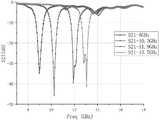
图3为实施例的2-4GHz频段的带阻滤波单元的测试性能图;Fig. 3 is the test performance diagram of the band stop filtering unit of the 2-4GHz frequency band of the embodiment;
图4为实施例的9-13.7GHz频段的带阻滤波单元的测试性能图。FIG. 4 is a test performance diagram of the band rejection filter unit in the 9-13.7 GHz frequency band of the embodiment.
具体实施方式detailed description
下面结合附图对本发明作进一步的阐述说明,应该说明的是,本发明的实施方式并不限于所提供的实施例。The present invention will be further described below in conjunction with the accompanying drawings. It should be noted that the embodiments of the present invention are not limited to the provided examples.
参阅图1-4所示,本发明提供如下实施例:Referring to shown in Fig. 1-4, the present invention provides following embodiment:
在本发明实施例方案中,提供的2-18GHz频段中心频率连续可调宽带带阻滤波器,包括四个工作在不同频段的带阻滤波单元,分别为:工作在2-4GHz频段的第一带阻滤波单元、工作在4-9GHz频段的第二带阻滤波单元、工作在9-13.7GHz频段的第三带阻滤波单元以及工作在13.7-18GHz频段的第四带阻滤波单元;In the solution of the embodiment of the present invention, the continuously adjustable wideband band-stop filter with center frequency in the 2-18GHz frequency band includes four band-stop filter units working in different frequency bands, namely: the first band-stop filter unit working in the 2-4GHz frequency band A band-stop filter unit, a second band-stop filter unit working in the 4-9GHz frequency band, a third band-stop filter unit working in the 9-13.7GHz frequency band, and a fourth band-stop filter unit working in the 13.7-18GHz frequency band;
所述的四个带阻滤波单元均包括:微带主传输线,以及微带主传输线两侧沿微带主传输线长度方向周期性分布的多个微带谐振器,微带谐振器与微带主传输线缝隙耦合,且每个微带谐振器上均加载有变容二极管,通过改变所述变容二极管加载的容值实现阻带中心频率的连续可调。The four band-stop filter units all include: a main microstrip transmission line, and a plurality of microstrip resonators periodically distributed along the length direction of the main microstrip transmission line on both sides of the main microstrip transmission line, the resonators and the main microstrip The transmission line is gap-coupled, and each microstrip resonator is loaded with a varactor diode, and the center frequency of the stop band can be continuously adjusted by changing the capacitance loaded by the varactor diode.
在上述实施例中,将2GHz—18GHz的频率调节范围划分为四个频段,分别对应四个可独立调节的带阻滤波单元,可通过切换不同的带阻滤波单元工作,从而实现整个2GHz—18GHz频率范围内的阻带连续可调。进一步的,带阻滤波单元采用50Ω微带主传输线,两侧分布多个微带谐振器,从而将阻带频率内的能量耦合到地,实现带阻滤波的功能。本实施例中采用的微带分布式周期滤波电路结构具有高抑制度、低插入损耗、宽调节范围的特点,采用分布式周期滤波电路结构,可以增加阻带抑制度,实现良好通带性能,有利于减小电路面积。In the above-mentioned embodiment, the frequency adjustment range of 2GHz-18GHz is divided into four frequency bands, corresponding to four independently adjustable band-stop filter units, and the entire 2GHz-18GHz can be realized by switching different band-stop filter units to work. The stopband is continuously adjustable over the frequency range. Furthermore, the band-stop filter unit adopts a 50Ω microstrip main transmission line, and a plurality of microstrip resonators are distributed on both sides, so as to couple the energy in the stop-band frequency to the ground and realize the function of band-stop filtering. The microstrip distributed periodic filter circuit structure used in this embodiment has the characteristics of high rejection, low insertion loss, and wide adjustment range. The distributed periodic filter circuit structure can increase the stopband rejection and achieve good passband performance. It is beneficial to reduce the circuit area.
参阅图1所示,在一些实施例中,所述第一带阻滤波单元和第二带阻滤波单元的微带谐振器均配置为四分之一波长终端短路的微带谐振器,每个微带谐振器可等效为LC并联谐振结构,通过窄缝耦合实现J/K变换器。更为具体的,所述第一带阻滤波单元和第二带阻滤波单元均设置为:微带谐振器包括第一微带线2和第二微带线3,第一微带线2的一端通过金属化通孔接地,另一端通过变容二极管C1连接第二微带线3的一端,第二微带线3的另一端通过变容二极管C2连接金属化通孔后进行接地,变容二极管C1和C2的阴极均连接第二微带线3,第一微带线2与主微带传输线1缝隙耦合,所有微带谐振器的第二微带线分别通过依次连接的隔交电阻(本实施例设置R1、R2两个隔交电阻)和直流偏置线4共同连接一个直流电压偏置。微带谐振器的谐振频率由微带线(第一微带线2和第二微带线3)感值容值及变容二极管(C1和C2)加载电容值共同决定,通过改变变容二极管加载的容值即可实现阻带中心频率的连续可调。Referring to FIG. 1, in some embodiments, the microstrip resonators of the first band-stop filter unit and the second band-stop filter unit are all configured as microstrip resonators with a quarter-wavelength short-circuited terminal, each The microstrip resonator can be equivalent to an LC parallel resonant structure, and a J/K converter can be realized through narrow slot coupling. More specifically, the first band-stop filter unit and the second band-stop filter unit are both configured as follows: the microstrip resonator includes a
参阅图2所示,在一些实施例中,所述第三带阻滤波单元和第四带阻滤波单元的微带谐振器均配置为半波长终端开路微带谐振器,每个微带谐振器可等效为LC并联谐振结构,通过窄缝耦合实现J/K变换器。具体的,所述第三带阻滤波单元和第四带阻滤波单元均设置为:微带谐振器包括第三微带线5和第四微带线6,第三微带线5与第四微带线6垂直连接,第四微带线6一端通过变容二极管C3连接金属化通孔后进行接地,第三微带线5与微带主传输线1缝隙耦合,所有微带谐振器的第三微带线5分别通过依次连接的隔交电阻(本实施例设置R3、R4两个隔交电阻)和直流偏置线共同连接一个直流电压偏置。同样的,在本实施例中,微带谐振器的谐振频率由微带线(第三微带线5和第四微带线6)感值容值及变容二极管(C3)加载电容值共同决定,通过改变变容二极管加载的容值即可实现阻带中心频率的连续可调。Referring to FIG. 2, in some embodiments, the microstrip resonators of the third band-stop filter unit and the fourth band-stop filter unit are all configured as half-wavelength terminal open-circuit microstrip resonators, and each microstrip resonator It can be equivalent to an LC parallel resonant structure, and a J/K converter can be realized through narrow slot coupling. Specifically, the third band-stop filter unit and the fourth band-stop filter unit are both configured as follows: the microstrip resonator includes a
以上实施例中,通过在不同频率段使用不同结构的微带谐振器,减小了整体电路面积,并且优化了滤波器的通带性能,减小信号损耗。高频率段使用加载变容二极管的半波长开路微带谐振器,通过减少微带谐振器数量从而减少了变容二极管的使用,降低了整体滤波器的成本。In the above embodiments, by using microstrip resonators with different structures in different frequency bands, the overall circuit area is reduced, and the passband performance of the filter is optimized to reduce signal loss. The half-wavelength open-circuit microstrip resonator loaded with varactor diodes is used in the high-frequency section, and the use of varactor diodes is reduced by reducing the number of microstrip resonators, which reduces the cost of the overall filter.
可以理解的是,在第一和第二带阻滤波单元中,第一微带线与主微带传输线之间为缝隙耦合,即具有耦合间距S,同样的,在第三和第四带阻滤波单元中,第三微带线与主微带传输线之间为缝隙耦合,具有同样的耦合间距S,通过调整耦合间距S可改变耦合强度,从而改变整个带阻滤波单元的带宽与阻带抑制度,而通过调节微带线(第一至第四微带线)的长度可改变带宽与谐振器谐振频率,增加微带主传输线两侧的微带谐振器的数量能够增加阻带抑制度,减小带宽。因此,根据设计所需频率及抑制度指标,可合理选择耦合间距S、微带线长度以及微带主传输线两侧加载的微带谐振器的数量。It can be understood that, in the first and second band-stop filter units, there is a gap coupling between the first microstrip line and the main microstrip transmission line, that is, there is a coupling spacing S. Similarly, in the third and fourth band-stop In the filter unit, the gap coupling between the third microstrip line and the main microstrip transmission line has the same coupling spacing S. By adjusting the coupling spacing S, the coupling strength can be changed, thereby changing the bandwidth and stopband suppression of the entire band-stop filter unit. degree, and the bandwidth and the resonant frequency of the resonator can be changed by adjusting the length of the microstrip line (the first to the fourth microstrip line), increasing the number of microstrip resonators on both sides of the main transmission line of the microstrip can increase the stopband suppression degree, Reduce bandwidth. Therefore, according to the frequency and rejection index required by the design, the coupling spacing S, the length of the microstrip line, and the number of microstrip resonators loaded on both sides of the main transmission line of the microstrip can be reasonably selected.
作为一种优选的实施方式,微带主传输线1的宽度为1.52mm,在第一带阻滤波单元中,第一微带线2的长度为5.2mm,第二微带线3的长度为1mm,第一微带线2与微带主传输线1的间距为0.1mm,微带谐振器的数量为22个,以达到30dB的阻带抑制度与较宽的调节范围;在第二带阻滤波单元中,第一微带线2的长度为3.2mm,第二微带线3的长度为0.6mm,第一微带线2与微带主传输线1的间距为0.1mm,微带谐振器的数量为20个。进一步优选的,在第三阻带滤波单元中,第三微带线5的长度为4.5mm,第四微带线6的长度为0.6mm,第三微带线5与微带主传输线1的间距为0.2mm,微带谐振器的数量为6个;在第四阻带滤波单元中,第三微带线5的长度为2.5mm,第四微带线6的长度为0.6mm,第三微带线5与微带主传输线1的间距为0.1mm,微带谐振器的数量为6个。参阅图3和图4,图3为本实施例的2-4GHz频段的带阻滤波单元的测试性能图,图4为本实施例的9-13.7GHz频段的带阻滤波单元的测试性能图;可以得出,实施例所提供的带阻滤波器可实现2-18GHz频段中心频率连续可调,具有高抑制度、低插入损耗、宽调节范围的特点,实现了良好的通带性能。As a preferred embodiment, the width of the microstrip main transmission line 1 is 1.52 mm, and in the first band-stop filter unit, the length of the
为减小滤波器体积,将四段滤波器电路加工于同一块电路板上,使用铝制屏蔽腔体进行封装,整体的滤波器封装腔体体积为:200mm*100mm*60mm。In order to reduce the size of the filter, the four-stage filter circuit is processed on the same circuit board and packaged in an aluminum shielding cavity. The overall filter package cavity volume is: 200mm*100mm*60mm.
在一些实施例中,每个带阻滤波单元的微带主传输线两端分别连接选通开关,所述选通开关通过计数字控制电路与控制端连接,通过控制端输入控制信号从而控制相应选通开关的导通,同时调节所导通的选通开关对应的带阻滤波单元中的变容二极管上加载的偏置电压。对于本发明中的频率可重构方式,采用调节工作在反偏状态下的变容二极管容值,进而改变整个谐振器谐振频率进行整个滤波器的阻带频率调节。通过数字控制电路输出不同电压值,对应扫描不同阻带频率,从而得到频率-电压的近似关系。计算机输入相应阻带频率,通过通讯协议与数字控制电路连接,数字电路输出对应控制电压,从而达到所期望的阻带频率。In some embodiments, the two ends of the microstrip main transmission line of each band-rejection filter unit are respectively connected to a gating switch, and the gating switch is connected to the control terminal through a digital control circuit, and a control signal is input through the control terminal to control the corresponding selection. The pass switch is turned on, and at the same time, the bias voltage loaded on the varactor diode in the band-stop filter unit corresponding to the turned-on gating switch is adjusted. For the frequency reconfigurable method in the present invention, the capacitance value of the varactor diode working in the reverse bias state is adjusted, and then the resonant frequency of the entire resonator is changed to adjust the stopband frequency of the entire filter. Different voltage values are output through the digital control circuit, and different stop band frequencies are correspondingly scanned, so as to obtain an approximate relationship between frequency and voltage. The computer inputs the corresponding stop band frequency, connects with the digital control circuit through the communication protocol, and the digital circuit outputs the corresponding control voltage, so as to achieve the desired stop band frequency.
以上所述,仅为本发明的具体实施方式,但本发明的保护范围并不局限于此,任何熟悉本技术领域的技术人员在本发明揭露的技术范围内,可轻易想到变化或替换,都应涵盖在本发明的保护范围之内。因此,本发明的保护范围应所述以权利要求的保护范围为准。The above is only a specific embodiment of the present invention, but the scope of protection of the present invention is not limited thereto. Anyone skilled in the art can easily think of changes or substitutions within the technical scope disclosed in the present invention. Should be covered within the protection scope of the present invention. Therefore, the protection scope of the present invention should be based on the protection scope of the claims.
Claims (7)
Translated fromChinesePriority Applications (1)
| Application Number | Priority Date | Filing Date | Title |
|---|---|---|---|
| CN202110543976.3ACN113488749B (en) | 2021-05-19 | 2021-05-19 | 2-18GHz frequency band center frequency continuously adjustable wideband band-stop filter |
Applications Claiming Priority (1)
| Application Number | Priority Date | Filing Date | Title |
|---|---|---|---|
| CN202110543976.3ACN113488749B (en) | 2021-05-19 | 2021-05-19 | 2-18GHz frequency band center frequency continuously adjustable wideband band-stop filter |
Publications (2)
| Publication Number | Publication Date |
|---|---|
| CN113488749A CN113488749A (en) | 2021-10-08 |
| CN113488749Btrue CN113488749B (en) | 2023-01-17 |
Family
ID=77932855
Family Applications (1)
| Application Number | Title | Priority Date | Filing Date |
|---|---|---|---|
| CN202110543976.3AExpired - Fee RelatedCN113488749B (en) | 2021-05-19 | 2021-05-19 | 2-18GHz frequency band center frequency continuously adjustable wideband band-stop filter |
Country Status (1)
| Country | Link |
|---|---|
| CN (1) | CN113488749B (en) |
Families Citing this family (2)
| Publication number | Priority date | Publication date | Assignee | Title |
|---|---|---|---|---|
| CN114914647B (en)* | 2022-05-17 | 2023-04-28 | 电子科技大学 | Tunable broadband band-stop filter based on ferrite material |
| CN115117580B (en)* | 2022-07-12 | 2024-04-30 | 安徽大学 | High rectangular coefficient semi-lumped millimeter wave filter chip based on cross-coupling structure |
Citations (3)
| Publication number | Priority date | Publication date | Assignee | Title |
|---|---|---|---|---|
| CN202210797U (en)* | 2011-09-28 | 2012-05-02 | 四川九立微波有限公司 | Front end assembly of frequency-selecting receiver of multichannel microwave communication machine |
| CN110061333A (en)* | 2019-04-04 | 2019-07-26 | 电子科技大学 | A kind of microwave electricity tune bandstop filter of high degree of suppression and broad tuning range |
| CN110911786A (en)* | 2019-11-28 | 2020-03-24 | 电子科技大学 | Reconfigurable high-rejection dual-band-stop filter |
- 2021
- 2021-05-19CNCN202110543976.3Apatent/CN113488749B/ennot_activeExpired - Fee Related
Patent Citations (3)
| Publication number | Priority date | Publication date | Assignee | Title |
|---|---|---|---|---|
| CN202210797U (en)* | 2011-09-28 | 2012-05-02 | 四川九立微波有限公司 | Front end assembly of frequency-selecting receiver of multichannel microwave communication machine |
| CN110061333A (en)* | 2019-04-04 | 2019-07-26 | 电子科技大学 | A kind of microwave electricity tune bandstop filter of high degree of suppression and broad tuning range |
| CN110911786A (en)* | 2019-11-28 | 2020-03-24 | 电子科技大学 | Reconfigurable high-rejection dual-band-stop filter |
Non-Patent Citations (1)
| Title |
|---|
| 《Tunable Bandstop Filter Using Distributed Coupling Microstrip Resonators With Capacitive Terminal》;Qun Li等;《IEEE MICROWAVE AND WIRELESS COMPONENTS LETTERS》;20191216;第30卷(第1期);附图1-5,正文第2节* |
Also Published As
| Publication number | Publication date |
|---|---|
| CN113488749A (en) | 2021-10-08 |
Similar Documents
| Publication | Publication Date | Title |
|---|---|---|
| Gómez-García et al. | Avoiding RF isolators: Reflectionless microwave bandpass filtering components for advanced RF front ends | |
| CN113488749B (en) | 2-18GHz frequency band center frequency continuously adjustable wideband band-stop filter | |
| CN113037240B (en) | Wide adjustable range band elimination filter device with continuous frequency adjustable characteristic | |
| CN105514547A (en) | Low-pass band-pass five-duplex based on novel frequency separation structure | |
| CN113904082A (en) | Dual microstrip line coupler, power amplifier and related device and chip | |
| CN115275545B (en) | A compact absorptive filter power splitter | |
| CN110429362B (en) | Reconfigurable filter based on T-shaped resonator | |
| CN104332681B (en) | Novel three-dimensional multilayer single-zero-point dual-mode filter | |
| CN104377411B (en) | Varactor loaded reconfigurable band rejection filter | |
| CN110061333A (en) | A kind of microwave electricity tune bandstop filter of high degree of suppression and broad tuning range | |
| US6064281A (en) | Semi-lumped bandpass filter | |
| CN110729538B (en) | A miniaturized ultra-wideband bandpass filter with reconfigurable notch band | |
| CN104009271B (en) | Planar band-pass filter based on four cascaded resonators | |
| CN115295985B (en) | Dual-passband bandpass filter and system suitable for dual-band communication system | |
| CN110034363A (en) | A kind of microwave electricity tune bandstop filter based on open-end microstrip line construction | |
| CN113451728B (en) | Miniaturized T-shaped dual-mode resonator | |
| CN205621824U (en) | Five multiplexers of low pass - band -pass based on novel frequency separation structure | |
| CN102569955B (en) | Dual-frequency band-pass filter based on asymmetric branch node loading resonator | |
| CN221102370U (en) | Ka-band-pass filter | |
| CN101916891A (en) | A UWB Bandpass Filter with Bandstop Characteristic | |
| CN207834544U (en) | A kind of duplexing filtered switch based on coupling control | |
| CN106252799B (en) | The orthogonal strap bandpass filter of millimeter waveguide | |
| Zahari et al. | Comparison of electronically switchable high Q Bandstop to bandpass filters based on allpass network | |
| CN215266609U (en) | Cross multimode band-pass filter | |
| Kada et al. | Dual-band SHF reconfigurable bandpass filter using λ/4 microstrip resonators and chip inductor coupling |
Legal Events
| Date | Code | Title | Description |
|---|---|---|---|
| PB01 | Publication | ||
| PB01 | Publication | ||
| SE01 | Entry into force of request for substantive examination | ||
| SE01 | Entry into force of request for substantive examination | ||
| GR01 | Patent grant | ||
| GR01 | Patent grant | ||
| CF01 | Termination of patent right due to non-payment of annual fee | Granted publication date:20230117 | |
| CF01 | Termination of patent right due to non-payment of annual fee |