CN113484605B - Charger super-high harmonic emission evaluation method and device and storage medium - Google Patents
Charger super-high harmonic emission evaluation method and device and storage mediumDownload PDFInfo
- Publication number
- CN113484605B CN113484605BCN202110759708.5ACN202110759708ACN113484605BCN 113484605 BCN113484605 BCN 113484605BCN 202110759708 ACN202110759708 ACN 202110759708ACN 113484605 BCN113484605 BCN 113484605B
- Authority
- CN
- China
- Prior art keywords
- ultra
- charger
- emission
- high harmonic
- parallel
- Prior art date
- Legal status (The legal status is an assumption and is not a legal conclusion. Google has not performed a legal analysis and makes no representation as to the accuracy of the status listed.)
- Active
Links
- 238000011156evaluationMethods0.000titleclaimsabstractdescription19
- 238000000034methodMethods0.000claimsabstractdescription37
- 238000004458analytical methodMethods0.000claimsabstractdescription28
- 238000004364calculation methodMethods0.000claimsabstractdescription7
- 230000015654memoryEffects0.000claimsdescription25
- 238000004891communicationMethods0.000claimsdescription4
- 230000001939inductive effectEffects0.000claimsdescription4
- 230000007246mechanismEffects0.000abstractdescription6
- 238000010586diagramMethods0.000description10
- 230000006870functionEffects0.000description4
- 230000008569processEffects0.000description3
- 238000012545processingMethods0.000description3
- 238000011160researchMethods0.000description3
- 238000004590computer programMethods0.000description2
- 238000012937correctionMethods0.000description2
- 238000011161developmentMethods0.000description2
- 230000000694effectsEffects0.000description2
- 238000012986modificationMethods0.000description2
- 230000004048modificationEffects0.000description2
- 230000003287optical effectEffects0.000description2
- 230000002159abnormal effectEffects0.000description1
- 230000002457bidirectional effectEffects0.000description1
- 238000004134energy conservationMethods0.000description1
- 238000005265energy consumptionMethods0.000description1
- 230000007613environmental effectEffects0.000description1
- 239000002360explosiveSubstances0.000description1
- 230000003993interactionEffects0.000description1
- 230000002452interceptive effectEffects0.000description1
- 238000003801millingMethods0.000description1
- 238000010295mobile communicationMethods0.000description1
- 230000035515penetrationEffects0.000description1
- 230000009467reductionEffects0.000description1
- 230000011664signalingEffects0.000description1
- 239000007787solidSubstances0.000description1
Images


Classifications
- G—PHYSICS
- G01—MEASURING; TESTING
- G01R—MEASURING ELECTRIC VARIABLES; MEASURING MAGNETIC VARIABLES
- G01R23/00—Arrangements for measuring frequencies; Arrangements for analysing frequency spectra
- G01R23/16—Spectrum analysis; Fourier analysis
- G—PHYSICS
- G01—MEASURING; TESTING
- G01R—MEASURING ELECTRIC VARIABLES; MEASURING MAGNETIC VARIABLES
- G01R19/00—Arrangements for measuring currents or voltages or for indicating presence or sign thereof
Landscapes
- Physics & Mathematics (AREA)
- General Physics & Mathematics (AREA)
- Mathematical Physics (AREA)
- Secondary Cells (AREA)
- Charge And Discharge Circuits For Batteries Or The Like (AREA)
Abstract
Description
Translated fromChinese技术领域technical field
本发明涉及电能质量分析技术领域,具体涉及一种充电机超高次谐波发射评估方法、装置及存储介质。The invention relates to the technical field of power quality analysis, in particular to a method, device and storage medium for evaluating ultra-high harmonic emission of a charger.
背景技术Background technique
随着节能降耗与环境保护政策的实施,清洁高效的能源利用成为主流,新型用能设备广泛接入,电力电子设备开关频率不断升高,充电机等设备制造商使用有源功率因数校正(Active Power Factor Correction,APFC)装置或PWM整流器等开关型电力电子设备来满足2kHz以下的低频谐波发射限值要求并提高设备的功率因数。采用这些技术会使得发射从低于2kHz的经典谐波向2kHz至150kHz范围内的更高频率的转移,从而引发了新的电能质量问题。研究发现,超高次谐波发射会导致诸多电气设备的工作异常,例如PLC抄表系统中智能电表与集中器通讯失败、数控铣床控制功能故障、触控调光灯控制失灵、漏电断路器意外跳闸、干扰医疗设备等。给电力用户和企业带来经济损失。With the implementation of energy conservation and consumption reduction and environmental protection policies, clean and efficient energy utilization has become the mainstream, new energy-consuming equipment is widely connected, the switching frequency of power electronic equipment continues to increase, and equipment manufacturers such as chargers use active power factor correction ( Active Power Factor Correction (APFC) devices or switching power electronic equipment such as PWM rectifiers to meet the low frequency harmonic emission limit requirements below 2kHz and improve the power factor of the equipment. Adoption of these techniques results in a shift of emissions from classical harmonics below 2 kHz to higher frequencies in the 2 kHz to 150 kHz range, causing new power quality issues. The study found that the emission of ultra-high harmonics can cause abnormal operation of many electrical equipment, such as the failure of communication between the smart meter and the concentrator in the PLC meter reading system, the failure of the control function of the CNC milling machine, the failure of the touch dimming lamp control, and the accident of the leakage circuit breaker. tripping, interfering with medical equipment, etc. Bring economic losses to power users and enterprises.
电动汽车充电机是典型的超高次谐波源之一,随着新能源汽车产业发展规划的提出与新基建的展开,电动汽车充电机迎来了爆发式增长。可以预见,随着充电机渗透率的提高、开关频率的升高,在不同环境下配电网中充电机引起的超高次谐波污染问题将更加严峻。充电机超高次谐波问题已成为极具必要性和紧迫性的新型电能质量专题。然而目前针对超高次谐波的研究尚处于起步阶段,对于充电机超高次谐波发射机理与评估方法的研究尚浅。Electric vehicle chargers are one of the typical sources of ultra-high harmonics. With the proposal of the new energy vehicle industry development plan and the development of new infrastructure, electric vehicle chargers have ushered in explosive growth. It is foreseeable that with the increase in the penetration rate of chargers and the increase in switching frequency, the problem of ultra-high harmonic pollution caused by chargers in the distribution network in different environments will be more severe. The problem of ultra-high harmonics in chargers has become a new type of power quality topic with great necessity and urgency. However, the research on ultra-high harmonics is still in its infancy, and the research on the emission mechanism and evaluation method of ultra-high harmonics of chargers is still shallow.
发明内容SUMMARY OF THE INVENTION
有鉴于此,本发明实施例提供了一种充电机超高次谐波发射评估方法、装置及存储介质,以解决现有技术中对于充电机超高次谐波发射机理与评估方法存在空缺的技术问题。In view of this, embodiments of the present invention provide a method, device, and storage medium for evaluating the emission of ultra-high harmonics of a charger, so as to solve the problems in the prior art for the emission mechanism and evaluation method of ultra-high harmonics of chargers. technical problem.
本发明提出的技术方案如下:The technical scheme proposed by the present invention is as follows:
本发明实施例第一方面提供一种充电机超高次谐波发射评估方法,包括:采用双重傅里叶分析法对单模块整流电路进行分析,建立单模块整流电路超高次谐波电压扰动模型;基于单模块整流电路超高次谐波电压扰动模型,构建多模块并联的单台充电机超高次谐波原生发射模型;基于单台充电机超高次谐波原生发射模型,计算单台充电机超高次谐波发射电流;根据电压扰动模型和单台充电机超高次谐波发射电流确定单台充电机超高次谐波电流频带分布规律与特征频带发射幅值。A first aspect of the embodiments of the present invention provides a method for evaluating ultra-high harmonic emission of a charger, including: using a double Fourier analysis method to analyze a single-module rectifier circuit, and establishing a single-module rectifier circuit ultra-high harmonic voltage disturbance Model; based on the ultra-high harmonic voltage disturbance model of the single-module rectifier circuit, build a multi-module parallel single charger ultra-high harmonic primary emission model; According to the voltage disturbance model and the ultra-high harmonic emission current of a single charger, determine the frequency distribution law of the ultra-high harmonic current of a single charger and the emission amplitude of the characteristic frequency band.
可选地,该充电机超高次谐波发射评估方法还包括:基于单台充电机超高次谐波原生发射模型,计算多台相同开关频率充电机并联的超高次谐波发射电流;根据电压扰动模型和多台相同开关频率充电机并联的超高次谐波发射电流确定多台相同开关频率充电机并联时超高次谐波电流频带分布规律与特征频带发射幅值。Optionally, the method for evaluating the ultra-high harmonic emission of the charger further includes: calculating the ultra-high harmonic emission current of multiple chargers with the same switching frequency in parallel based on the original ultra-high harmonic emission model of a single charger; According to the voltage disturbance model and the ultra-high harmonic emission current of multiple chargers with the same switching frequency in parallel, the frequency distribution law of the ultra-high harmonic current and the emission amplitude of the characteristic frequency band when multiple chargers with the same switching frequency are connected in parallel are determined.
可选地,该充电机超高次谐波发射评估方法还包括:基于单台充电机超高次谐波原生发射模型,计算多台不同开关频率充电机并联的超高次谐波发射电流;根据电压扰动模型和多台不同开关频率充电机并联的超高次谐波发射电流确定多台不同开关频率充电机并联时超高次谐波电流频带分布规律与特征频带发射幅值。Optionally, the method for evaluating the ultra-high harmonic emission of the charger further includes: calculating the ultra-high harmonic emission current of multiple chargers with different switching frequencies in parallel based on the original ultra-high harmonic emission model of a single charger; According to the voltage disturbance model and the ultra-high harmonic emission current of multiple chargers with different switching frequencies in parallel, the frequency distribution law of ultra-high harmonic current and the emission amplitude of characteristic frequency bands when multiple chargers with different switching frequencies are connected in parallel are determined.
可选地,单模块整流电路超高次谐波电压扰动模型包括:基于同相层叠式载波空间矢量调制的单模块整流电路超高次谐波电压扰动模型和基于反相层叠式载波空间矢量调制的单模块整流电路超高次谐波电压扰动模型。Optionally, the single-module rectifier circuit ultra-high-order harmonic voltage disturbance model includes: a single-module rectifier circuit ultra-high-order harmonic voltage disturbance model based on in-phase stacked carrier space vector modulation and a single-module rectifier circuit based on inverse stacked carrier space vector modulation. Ultrahigh harmonic voltage disturbance model for single-module rectifier circuit.
可选地,单台充电机超高次谐波发射电流通过以下公式计算得到:Optionally, the ultra-high harmonic emission current of a single charger is calculated by the following formula:

其中,


可选地,多台相同开关频率充电机并联时单台充电机的超高次谐波发射电流通过以下公式计算得到:Optionally, when multiple chargers with the same switching frequency are connected in parallel, the ultra-high harmonic emission current of a single charger can be calculated by the following formula:

其中,


可选地,两台不同开关频率充电机并联时第一充电机本身发射的超高次谐波电流通过以下公式计算得到:Optionally, when two chargers with different switching frequencies are connected in parallel, the ultra-high harmonic current emitted by the first charger itself can be calculated by the following formula:

其中,


本发明实施例第二方面提供一种充电机超高次谐波发射评估装置,包括:电路分析模块,用于采用双重傅里叶分析法对单模块整流电路进行分析,建立单模块整流电路超高次谐波电压扰动模型;模型构建模块,用于基于单模块整流电路超高次谐波电压扰动模型,构建多模块并联的单台充电机超高次谐波原生发射模型;电流计算模块,用于基于单台充电机超高次谐波原生发射模型,计算单台充电机超高次谐波发射电流;特征分析模块,用于根据电压扰动模型和单台充电机超高次谐波发射电流确定单台充电机超高次谐波电流频带分布规律与特征频带发射幅值。A second aspect of the embodiments of the present invention provides an evaluation device for ultra-high harmonic emission of a charger, including: a circuit analysis module for analyzing a single-module rectifier circuit using a double Fourier analysis method, and establishing a single-module rectifier circuit ultra-high-order harmonics. High-order harmonic voltage disturbance model; model building module, which is used to build a multi-module parallel single-charger ultra-high-order harmonic original emission model based on the single-module rectifier circuit ultra-high-order harmonic voltage disturbance model; current calculation module, It is used to calculate the ultra-high harmonic emission current of a single charger based on the ultra-high harmonic emission model of a single charger; the feature analysis module is used to transmit the ultra-high harmonics of a single charger based on the voltage disturbance model and the single charger. The current determines the frequency distribution law of the ultra-high harmonic current of a single charger and the emission amplitude of the characteristic frequency band.
本发明实施例第三方面提供一种计算机可读存储介质,所述计算机可读存储介质存储有计算机指令,所述计算机指令用于使所述计算机执行如本发明实施例第一方面及第一方面任一项所述的充电机超高次谐波发射评估方法。A third aspect of the embodiments of the present invention provides a computer-readable storage medium, where the computer-readable storage medium stores computer instructions, and the computer instructions are used to cause the computer to execute the first and first aspects of the embodiments of the present invention. The method for evaluating the ultra-high harmonic emission of a charger according to any one of the aspects.
本发明实施例第四方面提供一种电子设备,包括:存储器和处理器,所述存储器和所述处理器之间互相通信连接,所述存储器存储有计算机指令,所述处理器通过执行所述计算机指令,从而执行如本发明实施例第一方面及第一方面任一项所述的充电机超高次谐波发射评估方法。A fourth aspect of the embodiments of the present invention provides an electronic device, including: a memory and a processor, the memory and the processor are connected in communication with each other, the memory stores computer instructions, and the processor executes the computer instructions, thereby executing the method for evaluating the ultra-high harmonic emission of a charger according to any one of the first aspect and the first aspect of the embodiments of the present invention.
本发明提供的技术方案,具有如下效果:The technical scheme provided by the invention has the following effects:
本发明实施例提供的充电机超高次谐波发射评估方法、装置及存储介质,通过采用双重傅里叶分析法对单模块整流电路进行分析,建立单模块整流电路超高次谐波电压扰动模型;基于该模型构建了多模块并联的单台充电机超高次谐波原生发射模型;由此计算得到单台充电机超高次谐波发射电流;从电压扰动模型和单台充电机超高次谐波发射电流可以确定单台充电机超高次谐波电流频带分布规律与特征频带发射幅值。由此,该评估方法通过对单模块整流电路的分析,实现了对多模块并联的充电机超高次谐波发射电流的计算和分析,弥补了现有技术中对于充电机超高次谐波发射机理与评估方法存在的空缺。According to the method, device and storage medium for evaluating ultra-high harmonic emission of a charger provided by the embodiment of the present invention, the single-module rectifier circuit is analyzed by using the double Fourier analysis method, and the ultra-high harmonic voltage disturbance of the single-module rectifier circuit is established. model; based on this model, a multi-module parallel single charger UHF native emission model is constructed; from this, the ultra-high harmonic emission current of a single charger is calculated; from the voltage disturbance model and the single charger ultra-high harmonic emission The high-order harmonic emission current can determine the frequency distribution law of the ultra-high-order harmonic current of a single charger and the emission amplitude of the characteristic frequency band. Therefore, the evaluation method realizes the calculation and analysis of the ultra-high harmonic emission current of the charger with multiple modules in parallel through the analysis of the single-module rectifier circuit, which makes up for the ultra-high harmonic emission of the charger in the prior art. There are gaps in launch mechanisms and evaluation methods.
附图说明Description of drawings
为了更清楚地说明本发明具体实施方式或现有技术中的技术方案,下面将对具体实施方式或现有技术描述中所需要使用的附图作简单地介绍,显而易见地,下面描述中的附图是本发明的一些实施方式,对于本领域普通技术人员来讲,在不付出创造性劳动的前提下,还可以根据这些附图获得其他的附图。In order to illustrate the specific embodiments of the present invention or the technical solutions in the prior art more clearly, the following briefly introduces the accompanying drawings that need to be used in the description of the specific embodiments or the prior art. Obviously, the accompanying drawings in the following description The drawings are some embodiments of the present invention. For those of ordinary skill in the art, other drawings can also be obtained based on these drawings without creative efforts.
图1是根据本发明实施例的充电机超高次谐波发射评估方法的流程图;1 is a flowchart of a method for evaluating ultra-high harmonic emission of a charger according to an embodiment of the present invention;
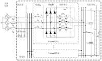
图2是根据本发明实施例的充电机电路拓扑结构图;2 is a circuit topology diagram of a charger according to an embodiment of the present invention;
图3是根据本发明实施例的多模块整流电路超高次谐波电压扰动模型示意图;3 is a schematic diagram of a multi-module rectifier circuit ultra-high-order harmonic voltage disturbance model according to an embodiment of the present invention;
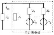
图4是根据本发明实施例的多模块并联的单台充电机超高次谐波原生发射模型示意图;FIG. 4 is a schematic diagram of a single charger with multiple modules connected in parallel with an ultra-high harmonic primary emission model according to an embodiment of the present invention;
图5是根据本发明另一实施例的充电机超高次谐波发射评估方法的流程图;5 is a flowchart of a method for evaluating ultra-high harmonic emission of a charger according to another embodiment of the present invention;
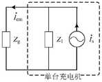
图6是根据本发明实施例的多台相同开关频率充电机并联示意图;6 is a schematic diagram of parallel connection of multiple chargers with the same switching frequency according to an embodiment of the present invention;
图7是根据本发明另一实施例的充电机超高次谐波发射评估方法的流程图;7 is a flowchart of a method for evaluating ultra-high harmonic emission of a charger according to another embodiment of the present invention;
图8是根据本发明实施例的两台不同开关频率充电机并联示意图;FIG. 8 is a schematic diagram of a parallel connection of two chargers with different switching frequencies according to an embodiment of the present invention;
图9是根据本发明实施例的充电机超高次谐波发射评估装置的结构框图;9 is a structural block diagram of a device for evaluating ultra-high harmonic emission of a charger according to an embodiment of the present invention;
图10是根据本发明实施例提供的计算机可读存储介质的结构示意图;10 is a schematic structural diagram of a computer-readable storage medium provided according to an embodiment of the present invention;
图11是根据本发明实施例提供的电子设备的结构示意图。FIG. 11 is a schematic structural diagram of an electronic device provided according to an embodiment of the present invention.
具体实施方式Detailed ways
为使本发明实施例的目的、技术方案和优点更加清楚,下面将结合本发明实施例中的附图,对本发明实施例中的技术方案进行清楚、完整地描述,显然,所描述的实施例是本发明一部分实施例,而不是全部的实施例。基于本发明中的实施例,本领域技术人员在没有做出创造性劳动前提下所获得的所有其他实施例,都属于本发明保护的范围。In order to make the purposes, technical solutions and advantages of the embodiments of the present invention clearer, the technical solutions in the embodiments of the present invention will be clearly and completely described below with reference to the accompanying drawings in the embodiments of the present invention. Obviously, the described embodiments These are some embodiments of the present invention, but not all embodiments. Based on the embodiments of the present invention, all other embodiments obtained by those skilled in the art without creative efforts shall fall within the protection scope of the present invention.
本发明实施例提供一种充电机超高次谐波发射评估方法,如图1所示,该评估方法包括如下步骤:An embodiment of the present invention provides an evaluation method for ultra-high harmonic emission of a charger. As shown in FIG. 1 , the evaluation method includes the following steps:
步骤S101:采用双重傅里叶分析法对单模块整流电路进行分析,建立单模块整流电路超高次谐波电压扰动模型;具体地,该整流电路可以选择Vieena型整流电路。Vieena型整流电路作为一种三电平拓扑,适用于高电压,大功率的研究领域,相比于传统的两电平拓扑结构,Vieena型整流电路可以有效降低开关管的电压应力以及交流侧的谐波含量;相比于二极管箝位型的三电平拓扑结构,其每个桥臂上只需要一个开关管,可以有效避免上下桥臂的直通问题,从而简化控制环节。Step S101 : using the double Fourier analysis method to analyze the single-module rectifier circuit, and establish a single-module rectifier circuit ultra-high-order harmonic voltage disturbance model; specifically, the rectifier circuit can select a Vieena type rectifier circuit. As a three-level topology, the Vieena rectifier circuit is suitable for high-voltage and high-power research fields. Compared with the traditional two-level topology, the Vieena rectifier circuit can effectively reduce the voltage stress of the switching tube and the voltage on the AC side. Harmonic content: Compared with the diode-clamped three-level topology, only one switch is required on each bridge arm, which can effectively avoid the shoot-through problem of the upper and lower bridge arms, thereby simplifying the control process.
在一实施例中,在分析时,首先确定Vieena型整流电路载波调制方法,采用双重傅里叶分析方法对单模块Vieena整流电路进行分析,在分析时假设实际调制比为M,直流侧电压为VDC。具体地,通过分析,可以建立基于同相/反相层叠式载波空间矢量调制的单模块Vieena型整流电路超高次谐波电压扰动模型。In one embodiment, during the analysis, the carrier modulation method of the Vieena type rectifier circuit is first determined, and the single-module Vieena rectifier circuit is analyzed by the double Fourier analysis method. In the analysis, it is assumed that the actual modulation ratio is M, and the DC side voltage is VDC . Specifically, through analysis, a single-module Vieena-type rectifier circuit ultra-high-order harmonic voltage disturbance model based on in-phase/inverse-phase stacked carrier space vector modulation can be established.
具体地,基于同相层叠式载波空间矢量调制的单模块Vieena型整流电路超高次谐波电压表达式为:Specifically, the ultra-high-order harmonic voltage expression of the single-module Vieena type rectifier circuit based on the in-phase stacked carrier space vector modulation is:
us=A1cos[(2m-1)ωct]+A2cos[2mωct+(2n-1)ωgt]+A3cos[(2m-1)ωct+2nωgt]us =A1 cos[(2m-1)ωc t]+A2 cos[2mωc t+(2n-1)ωg t]+A3 cos[(2m-1)ωc t+2nωg t ]
式中,


ωc为开关频率角频率,ωg为工频角频率,m和n均为整数,如0、±1、±2、±3……;J2k-1为2k-1次的贝塞尔函数,J2n+1为2n+1次的贝塞尔函数,M为调制比,VDC为直流侧电压。ωc is the switching frequency angular frequency, ωg is the power frequency angular frequency, m and n are integers, such as 0, ±1, ±2, ±3...; J2k-1 is the Bessel of 2k-1 times function, J2n+1 is the Bessel function of order 2n+1, M is the modulation ratio, and VDC is the DC side voltage.
基于反相层叠式载波空间矢量调制的单模块Vieena型整流电路超高次谐波电压表达式为:The ultra-high harmonic voltage expression of the single-module Vieena type rectifier circuit based on the inverse stacked carrier space vector modulation is:
us=A1 cos[mωct+(2n+1)ωgt]us =A1 cos[mωc t+(2n+1)ωg t]
式中:
步骤S102:基于单模块整流电路超高次谐波电压扰动模型,构建多模块并联的单台充电机超高次谐波原生发射模型。具体地,充电机可以是电动汽车充电机,也可以是用于电力,通讯,铁路,航船等领域中。Step S102: Based on the ultra-high-order harmonic voltage disturbance model of the single-module rectifier circuit, construct an ultra-high-order harmonic native emission model of a single charger with multiple modules connected in parallel. Specifically, the charger may be an electric vehicle charger, or may be used in fields such as electric power, communications, railways, and ships.
在一实施例中,多模块并联的单台充电机电路拓扑结构如图2所示,其中,整流电路为Vieena型整流电路,除Vieena模块外,该充电机电路还包括滤波器、电感Lb、整流桥、双向开关、直流母线以及外部输入的交流电源。多模块整流电路超高次谐波电压扰动模型如图3所示,其中,


步骤S103:基于单台充电机超高次谐波原生发射模型,计算单台充电机超高次谐波发射电流;具体地,基于上述图4构建的原生发射模型,则单台充电机超高次谐波发射电流通过以下公式计算得到:Step S103: Calculate the emission current of a single charger based on the ultra-high harmonics native emission model of a single charger; specifically, based on the native emission model constructed in FIG. The subharmonic emission current is calculated by the following formula:

其中,


步骤S104:根据电压扰动模型和单台充电机超高次谐波发射电流确定单台充电机超高次谐波电流频带分布规律与特征频带发射幅值。具体地,频带分布规律可以由电压扰动模型确定,即可以从基于同相层叠式载波空间矢量调制的单模块Vieena型整流电路超高次谐波电压表达式和基于反相层叠式载波空间矢量调制的单模块Vieena型整流电路超高次谐波电压表达式中确定。特征频带发射幅值可以由单台充电机超高次谐波发射电流表达式确定。Step S104: According to the voltage disturbance model and the ultra-high harmonic emission current of the single charger, determine the frequency band distribution law of the ultra-high harmonic current of the single charger and the emission amplitude of the characteristic frequency band. Specifically, the frequency band distribution law can be determined by the voltage disturbance model, that is, it can be determined from the ultra-high-order harmonic voltage expression of the single-module Vieena type rectifier circuit based on the in-phase stacked carrier space vector modulation and the one based on the inverse stacked carrier space vector modulation. The single-module Vieena-type rectifier circuit is determined in the expression of the ultra-high harmonic voltage. The emission amplitude of the characteristic frequency band can be determined by the expression of the ultra-high harmonic emission current of a single charger.
本发明实施例提供的充电机超高次谐波发射评估方法,通过采用双重傅里叶分析法对单模块整流电路进行分析,建立单模块整流电路超高次谐波电压扰动模型;基于该模型构建了多模块并联的单台充电机超高次谐波原生发射模型;由此计算得到单台充电机超高次谐波发射电流;从电压扰动模型和单台充电机超高次谐波发射电流可以确定单台充电机超高次谐波电流频带分布规律与特征频带发射幅值。由此,该评估方法通过对单模块整流电路的分析,实现了对多模块并联的充电机超高次谐波发射电流的计算和分析,弥补了现有技术中对于充电机超高次谐波发射机理与评估方法存在的空缺。In the method for evaluating the ultra-high harmonic emission of a charger provided by the embodiment of the present invention, a single-module rectifier circuit is analyzed by adopting a double Fourier analysis method, and a single-module rectifier circuit ultra-high harmonic voltage disturbance model is established; based on the model A multi-module parallel-connected single charger UHF native emission model is constructed; the UH harmonic emission current of a single charger is calculated from this; The current can determine the frequency distribution law of the ultra-high harmonic current of a single charger and the emission amplitude of the characteristic frequency band. Therefore, the evaluation method realizes the calculation and analysis of the ultra-high harmonic emission current of the charger with multiple modules in parallel through the analysis of the single-module rectifier circuit, which makes up for the ultra-high harmonic emission of the charger in the prior art. There are gaps in launch mechanisms and evaluation methods.
作为本发明实施例的一种可选的实施方式,如图5所示,该充电机超高次谐波发射评估方法还包括:As an optional implementation of the embodiment of the present invention, as shown in FIG. 5 , the method for evaluating the ultra-high harmonic emission of the charger further includes:
步骤S201:基于单台充电机超高次谐波原生发射模型,计算多台相同开关频率充电机并联的超高次谐波发射电流;具体地,当多台相同开关频率充电机并联时,其结构如图6所示,其中,


具体地,基于原生发射模型,计算的多台相同开关频率充电机并联时单台充电机超高次谐波发射电流可以通过以下公式计算得到:Specifically, based on the native emission model, the calculated ultra-high harmonic emission current of a single charger when multiple chargers with the same switching frequency are connected in parallel can be calculated by the following formula:

其中,


流入网侧的超高次谐波电流

步骤S202:根据电压扰动模型和多台相同开关频率充电机并联的超高次谐波发射电流确定多台相同开关频率充电机并联时超高次谐波电流频带分布规律与特征频带发射幅值。具体地,频带分布规律可以由电压扰动模型确定,即可以从基于同相层叠式载波空间矢量调制的单模块Vieena型整流电路超高次谐波电压表达式和基于反相层叠式载波空间矢量调制的单模块Vieena型整流电路超高次谐波电压表达式中确定。特征频带发射幅值可以由多台相同开关频率充电机并联的超高次谐波发射电流表达式确定。Step S202 : According to the voltage disturbance model and the ultra-high harmonic emission currents of multiple chargers with the same switching frequency in parallel, determine the frequency distribution law of the ultra-high harmonic current and the emission amplitude of the characteristic frequency band when the multiple chargers with the same switching frequency are connected in parallel. Specifically, the frequency band distribution law can be determined by the voltage disturbance model, that is, it can be determined from the single-module Vieena-type rectifier circuit based on the in-phase stacked carrier space vector modulation of the ultra-high harmonic voltage expression and the in-phase stacked carrier space vector modulation. The single-module Vieena-type rectifier circuit is determined in the expression of the ultra-high harmonic voltage. The emission amplitude of the characteristic frequency band can be determined by the expression of the ultra-high harmonic emission current of multiple chargers with the same switching frequency in parallel.
作为本发明实施例的一种可选的实施方式,如图7所示,该充电机超高次谐波发射评估方法还包括:As an optional implementation of the embodiment of the present invention, as shown in FIG. 7 , the method for evaluating the ultra-high harmonic emission of the charger further includes:
步骤S301:基于单台充电机超高次谐波原生发射模型,计算多台不同开关频率充电机并联的超高次谐波发射电流;在一实施例中,以两台不同开关频率充电机并联为例,如图8所示,为两台不同开关频率充电机并联示意图。其中,


两台不同开关频率充电机并联时第一充电机即充电机1本身发射的超高次谐波电流通过以下公式计算得到:When two chargers with different switching frequencies are connected in parallel, the ultra-high harmonic current emitted by the first charger, that is,

其中,


第一充电机即充电机1发射的超高次谐波电流


步骤S302:根据电压扰动模型和多台不同开关频率充电机并联的超高次谐波发射电流确定多台不同开关频率充电机并联时超高次谐波电流频带分布规律与特征频带发射幅值。具体地,频带分布规律可以由电压扰动模型确定,即可以从基于同相层叠式载波空间矢量调制的单模块Vieena型整流电路超高次谐波电压表达式和基于反相层叠式载波空间矢量调制的单模块Vieena型整流电路超高次谐波电压表达式中确定。特征频带发射幅值可以由多台不同开关频率充电机并联的超高次谐波发射电流表达式确定。Step S302 : According to the voltage disturbance model and the ultra-high harmonic emission currents of multiple chargers with different switching frequencies in parallel, determine the frequency distribution law of ultra-high harmonic currents and the emission amplitudes of characteristic frequency bands when multiple chargers with different switching frequencies are connected in parallel. Specifically, the frequency band distribution law can be determined by the voltage disturbance model, that is, it can be determined from the single-module Vieena-type rectifier circuit based on the in-phase stacked carrier space vector modulation of the ultra-high harmonic voltage expression and the in-phase stacked carrier space vector modulation. The single-module Vieena-type rectifier circuit is determined in the expression of the ultra-high harmonic voltage. The emission amplitude of the characteristic frequency band can be determined by the expression of the ultra-high harmonic emission current of multiple chargers with different switching frequencies in parallel.
本发明实施例还提供一种充电机超高次谐波发射评估装置,如图9所示,该装置包括:The embodiment of the present invention also provides a device for evaluating ultra-high harmonic emission of a charger, as shown in FIG. 9 , the device includes:
电路分析模块,用于采用双重傅里叶分析法对单模块整流电路进行分析,建立单模块整流电路超高次谐波电压扰动模型;详细内容参见上述方法实施例中步骤S101的相关描述。The circuit analysis module is used to analyze the single-module rectifier circuit by using the double Fourier analysis method, and establish a single-module rectifier circuit ultra-high-order harmonic voltage disturbance model; for details, refer to the relevant description of step S101 in the above method embodiment.
模型构建模块,用于基于单模块整流电路超高次谐波电压扰动模型,构建多模块并联的单台充电机超高次谐波原生发射模型;详细内容参见上述方法实施例中步骤S102的相关描述。The model building module is used to build a multi-module parallel-connected single charger ultra-high harmonic primary emission model based on the ultra-high harmonic voltage disturbance model of the single-module rectifier circuit; for details, please refer to step S102 in the above method embodiment for details. describe.
电流计算模块,用于基于单台充电机超高次谐波原生发射模型,计算单台充电机超高次谐波发射电流;详细内容参见上述方法实施例中步骤S103的相关描述。The current calculation module is used to calculate the ultra-high harmonic emission current of a single charger based on the original UH harmonic emission model of the single charger; for details, refer to the relevant description of step S103 in the above method embodiment.
特征分析模块,用于根据电压扰动模型和单台充电机超高次谐波发射电流确定单台充电机超高次谐波电流频带分布规律与特征频带发射幅值。详细内容参见上述方法实施例中步骤S104的相关描述。The characteristic analysis module is used to determine the frequency distribution law of the ultra-high harmonic current of a single charger and the emission amplitude of the characteristic frequency band according to the voltage disturbance model and the ultra-high harmonic emission current of a single charger. For details, refer to the relevant description of step S104 in the above method embodiments.
本发明实施例提供的充电机超高次谐波发射评估装置,通过采用双重傅里叶分析法对单模块整流电路进行分析,建立单模块整流电路超高次谐波电压扰动模型;基于该模型构建了多模块并联的单台充电机超高次谐波原生发射模型;由此计算得到单台充电机超高次谐波发射电流;从电压扰动模型和单台充电机超高次谐波发射电流可以确定单台充电机超高次谐波电流频带分布规律与特征频带发射幅值。由此,该评估装置通过对单模块整流电路的分析,实现了对多模块并联的充电机超高次谐波发射电流的计算和分析,弥补了现有技术中对于充电机超高次谐波发射机理与评估方法存在的空缺。The device for evaluating the ultra-high harmonic emission of the charger provided by the embodiment of the present invention analyzes the single-module rectifier circuit by adopting the double Fourier analysis method, and establishes a single-module rectifier circuit ultra-high harmonic voltage disturbance model; based on the model A multi-module parallel-connected single charger UHF native emission model is constructed; the UH harmonic emission current of a single charger is calculated from this; The current can determine the frequency distribution law of the ultra-high harmonic current of a single charger and the emission amplitude of the characteristic frequency band. Therefore, the evaluation device realizes the calculation and analysis of the ultra-high harmonic emission current of the charger with multiple modules in parallel through the analysis of the single-module rectifier circuit, which makes up for the ultra-high harmonic emission of the charger in the prior art. There are gaps in launch mechanisms and evaluation methods.
本发明实施例提供的充电机超高次谐波发射评估装置的功能描述详细参见上述实施例中充电机超高次谐波发射评估方法描述。For the functional description of the apparatus for evaluating the ultra-high harmonic emission of the charger provided by the embodiment of the present invention, refer to the description of the method for evaluating the ultra-high harmonic emission of the charger in the foregoing embodiment for details.
本发明实施例还提供一种存储介质,如图10所示,其上存储有计算机程序601,该指令被处理器执行时实现上述实施例中充电机超高次谐波发射评估方法的步骤。该存储介质上还存储有音视频流数据,特征帧数据、交互请求信令、加密数据以及预设数据大小等。其中,存储介质可为磁碟、光盘、只读存储记忆体(Read-Only Memory,ROM)、随机存储记忆体(Random Access Memory,RAM)、快闪存储器(Flash Memory)、硬盘(Hard Disk Drive,缩写:HDD)或固态硬盘(Solid-State Drive,SSD)等;所述存储介质还可以包括上述种类的存储器的组合。An embodiment of the present invention further provides a storage medium, as shown in FIG. 10 , on which a
本领域技术人员可以理解,实现上述实施例方法中的全部或部分流程,是可以通过计算机程序来指令相关的硬件来完成,所述的程序可存储于一计算机可读取存储介质中,该程序在执行时,可包括如上述各方法的实施例的流程。其中,所述存储介质可为磁碟、光盘、只读存储记忆体(Read-Only Memory,ROM)、随机存储记忆体(RandomAccessMemory,RAM)、快闪存储器(Flash Memory)、硬盘(Hard Disk Drive,缩写:HDD)或固态硬盘(Solid-State Drive,SSD)等;所述存储介质还可以包括上述种类的存储器的组合。Those skilled in the art can understand that all or part of the processes in the methods of the above embodiments can be completed by instructing relevant hardware through a computer program, and the program can be stored in a computer-readable storage medium. During execution, the processes of the embodiments of the above-mentioned methods may be included. Wherein, the storage medium may be a magnetic disk, an optical disk, a read-only memory (Read-Only Memory, ROM), a random access memory (Random Access Memory, RAM), a flash memory (Flash Memory), a hard disk (Hard Disk Drive) , abbreviation: HDD) or solid-state drive (Solid-State Drive, SSD), etc.; the storage medium may also include a combination of the above-mentioned types of memories.
本发明实施例还提供了一种电子设备,如图11所示,该电子设备可以包括处理器51和存储器52,其中处理器51和存储器52可以通过总线或者其他方式连接,图11中以通过总线连接为例。An embodiment of the present invention also provides an electronic device. As shown in FIG. 11 , the electronic device may include a
处理器51可以为中央处理器(Central Processing Unit,CPU)。处理器51还可以为其他通用处理器、数字信号处理器(Digital Signal Processor,DSP)、专用集成电路(Application Specific Integrated Circuit,ASIC)、现场可编程门阵列(Field-Programmable Gate Array,FPGA)或者其他可编程逻辑器件、分立门或者晶体管逻辑器件、分立硬件组件等芯片,或者上述各类芯片的组合。The
存储器52作为一种非暂态计算机可读存储介质,可用于存储非暂态软件程序、非暂态计算机可执行程序以及模块,如本发明实施例中的对应的程序指令/模块。处理器51通过运行存储在存储器52中的非暂态软件程序、指令以及模块,从而执行处理器的各种功能应用以及数据处理,即实现上述方法实施例中的充电机超高次谐波发射评估方法。As a non-transitory computer-readable storage medium, the
存储器52可以包括存储程序区和存储数据区,其中,存储程序区可存储操作系统、至少一个功能所需要的应用程序;存储数据区可存储处理器51所创建的数据等。此外,存储器52可以包括高速随机存取存储器,还可以包括非暂态存储器,例如至少一个磁盘存储器件、闪存器件、或其他非暂态固态存储器件。在一些实施例中,存储器52可选包括相对于处理器51远程设置的存储器,这些远程存储器可以通过网络连接至处理器51。上述网络的实例包括但不限于互联网、企业内部网、局域网、移动通信网及其组合。The
所述一个或者多个模块存储在所述存储器52中,当被所述处理器51执行时,执行如图1-8所示实施例中的充电机超高次谐波发射评估方法。The one or more modules are stored in the
上述电子设备具体细节可以对应参阅图1至图8所示的实施例中对应的相关描述和效果进行理解,此处不再赘述。The specific details of the above electronic device can be understood by referring to the corresponding descriptions and effects in the embodiments shown in FIG. 1 to FIG. 8 , and details are not repeated here.
虽然结合附图描述了本发明的实施例,但是本领域技术人员可以在不脱离本发明的精神和范围的情况下做出各种修改和变型,这样的修改和变型均落入由所附权利要求所限定的范围之内。Although the embodiments of the present invention have been described with reference to the accompanying drawings, various modifications and variations can be made by those skilled in the art without departing from the spirit and scope of the present invention, and such modifications and variations fall within the scope of the appended claims within the limits of the requirements.
Claims (10)
Translated fromChinese


Priority Applications (1)
| Application Number | Priority Date | Filing Date | Title |
|---|---|---|---|
| CN202110759708.5ACN113484605B (en) | 2021-07-05 | 2021-07-05 | Charger super-high harmonic emission evaluation method and device and storage medium |
Applications Claiming Priority (1)
| Application Number | Priority Date | Filing Date | Title |
|---|---|---|---|
| CN202110759708.5ACN113484605B (en) | 2021-07-05 | 2021-07-05 | Charger super-high harmonic emission evaluation method and device and storage medium |
Publications (2)
| Publication Number | Publication Date |
|---|---|
| CN113484605A CN113484605A (en) | 2021-10-08 |
| CN113484605Btrue CN113484605B (en) | 2022-04-22 |
Family
ID=77940880
Family Applications (1)
| Application Number | Title | Priority Date | Filing Date |
|---|---|---|---|
| CN202110759708.5AActiveCN113484605B (en) | 2021-07-05 | 2021-07-05 | Charger super-high harmonic emission evaluation method and device and storage medium |
Country Status (1)
| Country | Link |
|---|---|
| CN (1) | CN113484605B (en) |
Families Citing this family (1)
| Publication number | Priority date | Publication date | Assignee | Title |
|---|---|---|---|---|
| CN115684719A (en)* | 2023-01-03 | 2023-02-03 | 国网江西省电力有限公司电力科学研究院 | A broadband coupled harmonic analysis method and system for a new energy grid-connected system |
Citations (8)
| Publication number | Priority date | Publication date | Assignee | Title |
|---|---|---|---|---|
| JP2013247686A (en)* | 2012-05-23 | 2013-12-09 | Sharp Corp | Motor controller |
| CN105245092A (en)* | 2015-10-08 | 2016-01-13 | 青岛派克能源有限公司 | Pulse width modulation (PWM) rectifier using transformer leakage inductance as LCL filtering |
| JP2016163406A (en)* | 2015-02-27 | 2016-09-05 | ジョンソンコントロールズ ヒタチ エア コンディショニング テクノロジー(ホンコン)リミテッド | Active filter, motor drive device employing the same, and refrigeration device |
| CN106647332A (en)* | 2017-01-06 | 2017-05-10 | 南通华为电力设备有限公司 | Electric vehicle bidirectional charging discharging system design method |
| CN110210152A (en)* | 2019-06-06 | 2019-09-06 | 福州大学 | A kind of ultra harmonics source modeling method |
| CN111478565A (en)* | 2020-05-23 | 2020-07-31 | 西安科技大学 | Design method of higher harmonic suppression controller of VIENNA rectifier |
| CN111537796A (en)* | 2020-05-12 | 2020-08-14 | 华北电力大学 | A Ultra-High-Order Harmonic Measurement Method Based on Fixed-Frequency Asynchronous Sampling |
| CN112615378A (en)* | 2020-12-08 | 2021-04-06 | 深圳供电局有限公司 | Distribution network high-frequency resonance frequency shift method and device and computer readable storage medium |
Family Cites Families (1)
| Publication number | Priority date | Publication date | Assignee | Title |
|---|---|---|---|---|
| CN103036461B (en)* | 2011-09-29 | 2016-03-30 | 台达电子企业管理(上海)有限公司 | Three phase rectifier module, its system be suitable for and harmonic suppressing method |
- 2021
- 2021-07-05CNCN202110759708.5Apatent/CN113484605B/enactiveActive
Patent Citations (8)
| Publication number | Priority date | Publication date | Assignee | Title |
|---|---|---|---|---|
| JP2013247686A (en)* | 2012-05-23 | 2013-12-09 | Sharp Corp | Motor controller |
| JP2016163406A (en)* | 2015-02-27 | 2016-09-05 | ジョンソンコントロールズ ヒタチ エア コンディショニング テクノロジー(ホンコン)リミテッド | Active filter, motor drive device employing the same, and refrigeration device |
| CN105245092A (en)* | 2015-10-08 | 2016-01-13 | 青岛派克能源有限公司 | Pulse width modulation (PWM) rectifier using transformer leakage inductance as LCL filtering |
| CN106647332A (en)* | 2017-01-06 | 2017-05-10 | 南通华为电力设备有限公司 | Electric vehicle bidirectional charging discharging system design method |
| CN110210152A (en)* | 2019-06-06 | 2019-09-06 | 福州大学 | A kind of ultra harmonics source modeling method |
| CN111537796A (en)* | 2020-05-12 | 2020-08-14 | 华北电力大学 | A Ultra-High-Order Harmonic Measurement Method Based on Fixed-Frequency Asynchronous Sampling |
| CN111478565A (en)* | 2020-05-23 | 2020-07-31 | 西安科技大学 | Design method of higher harmonic suppression controller of VIENNA rectifier |
| CN112615378A (en)* | 2020-12-08 | 2021-04-06 | 深圳供电局有限公司 | Distribution network high-frequency resonance frequency shift method and device and computer readable storage medium |
Non-Patent Citations (2)
| Title |
|---|
| Space Vector Modulator for Vienna-Type Rectifiers;Rolando Burgos,Rixin Lai,Yunqing Pei,Fei (Fred) Wang;《IEEE TRANSACTIONS ON POWER ELECTRONICS》;20071008;全文* |
| 单相APFC型充电机超高次谐波产生机理分析;陶顺1要海江,刘云博,徐永海,钱叶牛;《电工电能新技术》;20201223;全文* |
Also Published As
| Publication number | Publication date |
|---|---|
| CN113484605A (en) | 2021-10-08 |
Similar Documents
| Publication | Publication Date | Title |
|---|---|---|
| CN107171313B (en) | A Simplified Electromagnetic Transient Modeling Method for MMC Systems Considering Negative Sequence Components | |
| CN107394818B (en) | A grid-connected operation control method and device for an energy storage battery based on an energy storage converter | |
| CN111697584A (en) | Harmonic distribution characteristic analysis method and system of hybrid direct current transmission system | |
| CN113131479B (en) | Ultrahigh harmonic prediction method and system generated by pulse width modulation | |
| CN109768565B (en) | Passive impedance adapter parameter design method and device suitable for flexible direct current | |
| CN108281986A (en) | The impedance modeling of voltage-controlled type virtual synchronous generator and method for analyzing stability | |
| CN114285050A (en) | Method, device and storage medium for suppressing DC side oscillation of flexible DC transmission system | |
| CN107070283A (en) | The improved model forecast Control Algorithm that a kind of inverter switching frequency is fixed | |
| CN111146804A (en) | Method and device for judging oscillation stability of wind power-flexible direct current transmission system | |
| CN113484605B (en) | Charger super-high harmonic emission evaluation method and device and storage medium | |
| CN111541263A (en) | Harmonic control strategy evaluation method, system and equipment for flexible direct current transmission system | |
| Kurtoğlu et al. | A novel nearest level modulation method with increased output voltage quality for modular multilevel converter topology | |
| Hang et al. | Space vector modulation strategy for VIENNA rectifier and load unbalanced ability | |
| CN107196540A (en) | A kind of modularization multi-level converter direct current harmonic suppressing method | |
| CN115473226A (en) | A VSC high-frequency impedance matrix modeling method and system based on closed-loop equations | |
| CN110556854A (en) | Static harmonic analysis method and system for grid-connected point of flexible direct-current power transmission system | |
| CN108092534B (en) | Control method and device for single-phase five-level converter | |
| CN114725943B (en) | A control method, system, device and medium for an active filter | |
| CN113179037B (en) | Switching frequency modulation method and device and storage medium | |
| CN110429852A (en) | A kind of method, system and terminal device inhibiting inverter switching device circulation | |
| CN206921090U (en) | MMC real-time simulation system based on GPU | |
| CN117791540A (en) | A DC side filter design method and device for a multi-terminal high voltage DC system | |
| CN112615378B (en) | Distribution network high-frequency resonance frequency shift method and device and computer readable storage medium | |
| CN109245144B (en) | Method and device for determining power operation domain of hybrid modular multilevel converter | |
| CN103715875A (en) | Switching frequency adjusting method and device and inverters |
Legal Events
| Date | Code | Title | Description |
|---|---|---|---|
| PB01 | Publication | ||
| PB01 | Publication | ||
| SE01 | Entry into force of request for substantive examination | ||
| SE01 | Entry into force of request for substantive examination | ||
| GR01 | Patent grant | ||
| GR01 | Patent grant |