CN113400386B - Textile cutting device - Google Patents
Textile cutting deviceDownload PDFInfo
- Publication number
- CN113400386B CN113400386BCN202110782276.XACN202110782276ACN113400386BCN 113400386 BCN113400386 BCN 113400386BCN 202110782276 ACN202110782276 ACN 202110782276ACN 113400386 BCN113400386 BCN 113400386B
- Authority
- CN
- China
- Prior art keywords
- holding body
- textile
- cutter
- holding
- cutting
- Prior art date
- Legal status (The legal status is an assumption and is not a legal conclusion. Google has not performed a legal analysis and makes no representation as to the accuracy of the status listed.)
- Active
Links
Images


Classifications
- B—PERFORMING OPERATIONS; TRANSPORTING
- B26—HAND CUTTING TOOLS; CUTTING; SEVERING
- B26D—CUTTING; DETAILS COMMON TO MACHINES FOR PERFORATING, PUNCHING, CUTTING-OUT, STAMPING-OUT OR SEVERING
- B26D3/00—Cutting work characterised by the nature of the cut made; Apparatus therefor
- B26D3/18—Cutting work characterised by the nature of the cut made; Apparatus therefor to obtain cubes or the like
- B26D3/22—Cutting work characterised by the nature of the cut made; Apparatus therefor to obtain cubes or the like using rotating knives
- B—PERFORMING OPERATIONS; TRANSPORTING
- B26—HAND CUTTING TOOLS; CUTTING; SEVERING
- B26D—CUTTING; DETAILS COMMON TO MACHINES FOR PERFORATING, PUNCHING, CUTTING-OUT, STAMPING-OUT OR SEVERING
- B26D7/00—Details of apparatus for cutting, cutting-out, stamping-out, punching, perforating, or severing by means other than cutting
- B26D7/01—Means for holding or positioning work
- B26D7/02—Means for holding or positioning work with clamping means
- B26D7/025—Means for holding or positioning work with clamping means acting upon planar surfaces
- D—TEXTILES; PAPER
- D06—TREATMENT OF TEXTILES OR THE LIKE; LAUNDERING; FLEXIBLE MATERIALS NOT OTHERWISE PROVIDED FOR
- D06H—MARKING, INSPECTING, SEAMING OR SEVERING TEXTILE MATERIALS
- D06H7/00—Apparatus or processes for cutting, or otherwise severing, specially adapted for the cutting, or otherwise severing, of textile materials
- G—PHYSICS
- G01—MEASURING; TESTING
- G01N—INVESTIGATING OR ANALYSING MATERIALS BY DETERMINING THEIR CHEMICAL OR PHYSICAL PROPERTIES
- G01N1/00—Sampling; Preparing specimens for investigation
- G01N1/28—Preparing specimens for investigation including physical details of (bio-)chemical methods covered elsewhere, e.g. G01N33/50, C12Q
- G01N1/286—Preparing specimens for investigation including physical details of (bio-)chemical methods covered elsewhere, e.g. G01N33/50, C12Q involving mechanical work, e.g. chopping, disintegrating, compacting, homogenising
- G01N2001/2873—Cutting or cleaving
Landscapes
- Life Sciences & Earth Sciences (AREA)
- Engineering & Computer Science (AREA)
- Forests & Forestry (AREA)
- Mechanical Engineering (AREA)
- Health & Medical Sciences (AREA)
- Physics & Mathematics (AREA)
- Textile Engineering (AREA)
- Chemical & Material Sciences (AREA)
- Analytical Chemistry (AREA)
- Biochemistry (AREA)
- General Health & Medical Sciences (AREA)
- General Physics & Mathematics (AREA)
- Immunology (AREA)
- Pathology (AREA)
- Treatment Of Fiber Materials (AREA)
Abstract
Description
Translated fromChinese技术领域technical field
本发明涉及切碎纺织品以制备检测样品的技术,具体为一种纺织品切割装置,其包含机架、握持部件、切刀及切刀驱动装置,所述握持部件包含第一握持体与第二握持体,至少在纺织品一侧的握持体的长条状结构部件内包含有针状物,至少在纺织品一侧握持体长条状结构部件包含软弹性材料,所述切刀包括刀轴及安装在刀轴上的至少一个刀片,刀轴通过切刀驱动装置活动安装在机架上,第一握持体、第二握持体两者之中至少有一个活动安装在机架上,所述纺织品切割装置含有压紧装置,压紧装置在切刀和握持体之间利用弹性力或重力将第二握持体与第一握持体压紧,本发明所述纺织品切割装置能确保纺织品被切割过程中握持牢固,从而确保将纺织品切开、不粘连。The present invention relates to a technology for shredding textiles to prepare testing samples, in particular to a textile cutting device comprising a frame, a holding part, a cutter and a cutter driving device, the holding part comprising a first holding body and The second holding body contains needles in the elongated structural part of the holding body at least on the textile side; the long structural part of the holding body at least on the textile side contains a soft elastic material; the cutter It includes a cutter shaft and at least one blade mounted on the cutter shaft, the cutter shaft is movably installed on the frame through the cutter drive device, and at least one of the first holding body and the second holding body is movably installed on the machine. On the rack, the textile cutting device includes a pressing device, and the pressing device uses elastic force or gravity between the cutting knife and the holding body to press the second holding body and the first holding body. The cutting device ensures that the textiles are held firmly during the cutting process, thus ensuring that the textiles are cut without sticking.
背景技术Background technique
在纺织品检测领域,经常需要将片状的纺织品(例如织物、非织造布、织物复合的皮尤等)切碎用于各种指标的检测,例如在检测纺织品水淬取液pH值及其甲醛含量的测试中,需要将被侧纺织品剪切为5mm左右的小方块,并且需要将剪碎的纺织品试样分别放入容器中制备多个平行试样。目前,相关工作主要依靠人工完成,由于需要测试的纺织品数量很大,检测机构需要大量人员手工用剪刀将纺织品剪切为碎的试样。In the field of textile testing, sheet-like textiles (such as fabrics, non-woven fabrics, fabric composite Pew, etc.) are often required to be shredded for the detection of various indicators, such as the detection of the pH value of textile water extract and its formaldehyde In the content test, the textile on the side needs to be cut into small squares of about 5mm, and the cut textile samples need to be placed in containers to prepare multiple parallel samples. At present, the related work is mainly done manually. Due to the large number of textiles to be tested, the testing institution requires a large number of personnel to manually cut the textiles into broken samples with scissors.
目前有能够切碎纺织品的机器,一种是采用螺旋刀切断布样,螺旋刀对安装调整的要求较高,并且易磨损,刀具磨损后导致切割不彻底,另一方面,采用螺旋刀切碎的纺织品碎片不容易实现自动按重量分样,也就是说,用螺旋刀切碎后的布样由于状态杂乱,很难将切碎后的布样按照检测规程的要求分别自动定量放入烧杯或锥形瓶等容器中。还有将布样铺在垫板上用滚刀片裁布的裁布机,由于裁布过程中刀刃会切入垫板中,导致有时候纺织品纤维会进入垫板切割缝隙中,容易污染后续试样。At present, there are machines that can shred textiles. One is to use a spiral knife to cut fabric samples. The spiral knife has high requirements for installation and adjustment, and is easy to wear. After the tool is worn, the cutting is not complete. It is not easy to achieve automatic sample separation by weight, that is to say, the cloth samples chopped with a spiral knife are in a messy state, and it is difficult to automatically quantitatively put the chopped cloth samples into a beaker or a beaker according to the requirements of the testing regulations. Conical flasks and other containers. There is also a cloth cutting machine that lays the cloth sample on the backing plate and uses a roller blade to cut the cloth. Because the blade will cut into the backing plate during the cutting process, sometimes the textile fibers will enter the cutting gap of the backing plate, which is easy to contaminate the subsequent samples. .
发明专利申请“一种纺织品切碎方法及纺织品切碎装置”(申请号2019100558152)采用行、列排列的多根针状物刺透纺织品后将纺织品固定在针状物上,之后首先利用切刀沿针状物的行排列方向将纺织品切割为条状,再沿针状物排列方向切割为碎片,该方法虽然能整体固定住织物,但是,在切刀切割织物的过程中,由于两针状物之间对织物的握持不够,导致会有纱线无法切断,特别是位于针状物之间织物上的纱线,最常见的情况是,当沿织物经向或纬向与切刀方向相同时,第一次切割时与切刀方向平行的、位于切缝处的纱线在第二次被切割时容易切不断,并且,织物第一次与第二次切割旋转后针状物阵列与握持部件之间对齐的难度较大,装置安装调整的难度很大,很难达到预期的效果。The invention patent application "a textile shredding method and textile shredding device" (application number 2019100558152) uses a plurality of needles arranged in rows and columns to penetrate the textile and fix the textile on the needle, and then first use a cutter The textile is cut into strips along the row direction of the needles, and then cut into pieces along the needle array direction. Although this method can fix the fabric as a whole, in the process of cutting the fabric by the cutter, due to the two needles. Insufficient grip of the fabric between the objects, resulting in yarns that cannot be cut, especially those on the fabric between the needles. At the same time, the yarn at the slit that is parallel to the direction of the cutter when the first cut is cut is easy to be cut continuously when the second is cut, and the needle array is rotated after the first and second cuts of the fabric. It is difficult to align with the holding parts, and it is very difficult to install and adjust the device, and it is difficult to achieve the expected effect.
现有纺织品碎片切割制备技术中,切割纺织品时,如果不握持住纺织品进行切割,则需要在纺织品下面垫一层衬垫,衬垫上被切刀切出的切缝容易被纺织品纤维污染;握持住纺织品进行切割时,只靠上下两面握持很难握持牢,纺织品在被切割过程中会移位,导致切不开。鉴于以上问题,本发明公开一种纺织品切割装置,与现有技术相比,本发明所述纺织品切割装置能确保纺织品被切割过程中握持牢固,防止纺织品被切割时发生移动退刀现象,从而确保将纺织品切开、不粘连,由于结构简单,对装配及调整的要求不高,用于分两次将纺织品切割成碎片,第一次切割将纺织品切割成条状,第二次沿与第一次切割方向相垂直的方向切割,将条状的纺织品切割成小块。In the existing textile cutting preparation technology, when cutting the textile, if the textile is not held for cutting, a layer of lining needs to be placed under the textile, and the slits cut by the cutter on the lining are easily contaminated by textile fibers; When holding the textile for cutting, it is difficult to hold it firmly by only holding the upper and lower sides, and the textile will shift during the cutting process, resulting in inability to cut. In view of the above problems, the present invention discloses a textile cutting device. Compared with the prior art, the textile cutting device of the present invention can ensure that the textiles are firmly held during the cutting process, and prevent the moving and retracting phenomenon of the textiles when the textiles are being cut. Make sure that the textile is cut and not sticking. Due to the simple structure, the requirements for assembly and adjustment are not high. It is used to cut the textile into pieces in two times. Cut the strip of textile into small pieces with one cut in a direction perpendicular to the cutting direction.
发明内容SUMMARY OF THE INVENTION
对现有技术的不足,本发明要解决的技术问题是,提供一种纺织品切割装置,其解决方案是:To the deficiencies of the prior art, the technical problem to be solved by the present invention is to provide a textile cutting device, the solution of which is:
一种纺织品切割装置,其特征在于其包含机架、握持部件、切刀及切刀驱动装置,A textile cutting device is characterized in that it comprises a frame, a holding part, a cutter and a cutter driving device,
所述握持部件包含第一握持体与第二握持体,第一握持体及第二握持体具有平行、间隔排列的长条状结构部件用于夹持纺织品,第一握持体及第二握持体夹持纺织品时,其长条结构部件在纺织品的两侧面对齐,至少在纺织品一侧的握持体的长条状结构部件内包含有针状物,所述针状物互相平行、呈行列排列,其内含有针状物的握持体的每根长条状结构中至少有一行针状物,所述针状物尖端由其所在的握持体指向纺织品另一侧的另一个握持体,针状物的长度方向与纺织品垂直。The holding parts include a first holding body and a second holding body. The first holding body and the second holding body have long strip-shaped structural parts arranged in parallel and spaced apart for holding textiles. When the body and the second holding body clamp the textile, the elongated structural parts thereof are aligned on both sides of the textile; The objects are parallel to each other and arranged in rows and columns, and there are at least one row of needles in each elongated structure of the holding body containing needles, and the tips of the needles point from the holding body where they are located to the other side of the textile. The other holding body on the side, the length of the needle is perpendicular to the textile.
握持部件直接或间接安装在机架上,所述握持部件的第一握持体、第二握持体两者之中至少有一个活动安装在机架上,至多有一个固定安装在机架上。第一握持体与第二握持体相邻安装,第一握持体与第二握持体接触时,第一握持体与第二握持体的长条状结构部件对齐。The holding part is directly or indirectly installed on the frame, at least one of the first holding body and the second holding body of the holding part is movably installed on the frame, and at most one is fixedly installed on the machine. on the shelf. The first holding body and the second holding body are installed adjacent to each other, and when the first holding body and the second holding body are in contact, the first holding body is aligned with the elongated structural components of the second holding body.
第一握持体与第二握持体能相向运动至接触,在第一握持体与第二握持体没有夹持住纺织品之前,所述针状物的尖端在握持体中,针状物的尖端不伸出握持体与纺织品接触的表面,当相向压紧第一握持体与第二握持体夹紧纺织品时,所述针状物能伸出其所在侧握持体与纺织品接触的表面刺入纺织品中,所述针状物能伸出其所在侧的握持体与纺织品接触的表面是通过针状物与握持体的长条状结构相对运动或者握持体的长条状结构在针状物长度方向受压缩尺寸变小实现的。The first holding body and the second holding body can move toward each other until they are in contact, and before the first holding body and the second holding body do not clamp the textile, the tip of the needle-like object is in the holding body, and the needle-like object is in the holding body. The tip of the needle does not protrude from the surface of the grip body in contact with the textile, when the first grip body and the second grip body are pressed against each other to clamp the textile, the needle can extend out of the grip body on the side where it is in contact with the textile The surface of the needle-like object penetrates into the textile, and the surface of the holding body on the side where the needle-like object can extend in contact with the textile is through the relative movement of the needle-like object and the elongated structure of the holding body or the long strip of the holding body. The structure is realized by reducing the size of the compressed needle in the length direction of the needle.
至少在纺织品一侧的握持体的长条状结构部件与纺织品接触位置处包含软弹性材料,位于纺织品切刀一侧的握持体长条状结构部件在所夹持纺织品法线方向上具有通透的缝隙,用于穿过圆切刀。Soft elastic material is included at least at the position where the elongated structural part of the gripping body on the textile side is in contact with the textile, and the elongated structural part of the gripping body on the side of the textile cutter has in the normal direction of the clamped textile. See-through slit for passing round cutters.
所述切刀包括刀轴及安装在刀轴上的至少一个刀片,当一个切刀上含有多片刀片时,刀片之间等间距、对齐排列,刀片间距与针状物行间距或列间距相等,所有刀片的切削刃位于一个面上;切刀通过切刀驱动装置活动安装在机架上,切刀安装于握持部件的一侧,位于第一握持体与第二握持体之间的外侧,即切刀不位于第一握持体与第二握持体之间,切刀刀片与第一握持体与第二握持体的长条状结构部件间隔中部对齐,刀轴与握持体的长条状结构部件长度方向相垂直。切刀轴具有绕切刀轴轴线旋转的自由度,切刀驱动装置至少含有驱动切刀绕其轴心转动的转动驱动装置,切刀切割纺织品时,切刀穿过与其相邻的握持部件长条状结构部件上的通透缝隙切割纺织品。The cutter includes a cutter shaft and at least one blade mounted on the cutter shaft. When a cutter contains multiple blades, the blades are equally spaced and aligned, and the blade spacing is equal to the row spacing or column spacing of the needles. , the cutting edges of all blades are located on one surface; the cutter is movably installed on the frame through the cutter drive device, and the cutter is installed on one side of the holding part, located between the first holding body and the second holding body The outer side of the cutter, that is, the cutter is not located between the first holding body and the second holding body, the cutting blade is aligned with the middle of the interval between the long strip-shaped structural components of the first holding body and the second holding body, and the cutter shaft is aligned with the The longitudinal direction of the elongated structural parts of the holding body is perpendicular to each other. The cutter shaft has a degree of freedom to rotate around the axis of the cutter shaft, and the cutter drive device at least includes a rotary drive device that drives the cutter to rotate around its axis. When the cutter cuts textiles, the cutter passes through the adjacent holding part. Through slits on elongated structural parts cut textiles.
第一握持体、第二握持体与切刀三者中至少有两个在第一握持体与第二握持体接触面的法线方向上具有运动自由度,握持部件与切刀在握持体长条状结构部件长度方向具有相对运动自由度。At least two of the first holding body, the second holding body and the cutting knife have freedom of movement in the normal direction of the contact surface of the first holding body and the second holding body, and the holding part and the cutting blade have a degree of freedom of movement. The knife has relative freedom of movement in the length direction of the elongated structural member of the holding body.
籍由以上机构,需要切碎纺织品时,将纺织品放在第一握持体和第二握持体之间,第一握持体与第二握持体相向夹住被切割的纺织品,握持体中的针状物伸出其所在侧的握持体与纺织品接触的表面刺入纺织品中,切刀通过与其相邻的握持体长条状结构部件通透的缝隙开始切割纺织品,由于握持部件具有软弹性材料夹持纺织品,同时第一握持体与第二握持体之间有针状物刺入纺织品中,起到了强制固定纺织品的作用,纺织品在被切割过程中不会移动。纺织品被两种作用握持,一种是第一握持体与第二握持体的夹持,另一种是针状物的固定作用,如果仅依靠两面的握持体夹持纺织品很难将纺织品的所有位置握持牢固,即使与纺织品接触的表面为弹性材料制成,也很难在所有位置将纺织品握持牢固,因为,第一,纺织品在被夹持时很难一点折皱都没有,相对比较薄的地方就会握持不牢,即使能展平纺织品,有些纺织品厚度本身就不匀,即使第一次切割前是平整的,第一次切割成条状后进行第二次垂直方向切割时也不会是完全平整的状态,另一方面,纺织品两面的握持体也会有变形,也不会完全是一个平面,特别是在加压夹持时,握持体本身会弯曲变形,也会导致握持不牢。本发明采用了扎入纺织品的针状物起到定位纺织品防止其在针状物径向移动的作用,切割完纺织品后两握持体分开后针状物会缩回握持体内,不会挂住被切开的纺织品。Due to the above mechanism, when the textile needs to be chopped, the textile is placed between the first holding body and the second holding body, and the first holding body and the second holding body are opposite to clamp the cut textile, and hold the The needles in the body protrude from the surface of the holding body on the side where it is in contact with the textile and penetrate into the textile. The holding part has a soft elastic material to hold the textile, and at the same time, a needle is inserted into the textile between the first holding body and the second holding body, which plays the role of forcibly fixing the textile, and the textile will not move during the cutting process. . The textile is held by two functions, one is the clamping of the first holding body and the second holding body, and the other is the fixing function of the needle. It is difficult to hold the textile by only relying on the holding bodies on both sides. Hold the textile firmly in all places, even if the surface in contact with the textile is made of an elastic material, it is difficult to hold the textile firmly in all places because, first, the textile is difficult to hold without wrinkling at all , the relatively thin place will not hold firmly, even if the textile can be flattened, the thickness of some textiles itself is not uniform, even if it is flat before the first cut, the second vertical after the first cut into strips When cutting in the direction, it will not be completely flat. On the other hand, the holding body on both sides of the textile will also be deformed, and it will not be completely flat, especially when pressing and clamping, the holding body itself will bend Deformation can also lead to poor grip. The invention adopts the needle-shaped object inserted into the textile to position the textile to prevent it from moving in the radial direction of the needle-shaped object. After the textile is cut, the needle-shaped object will retract into the holding body after the two holding bodies are separated, and will not hang. Live cut textiles.
所述纺织品切割装置含有压紧装置,所述压紧装置安装在安装切刀的部件上,压紧装置在切刀和与其相邻的握持体之间,在切刀与纺织品接近的过程中,压紧装置接触握持体在先,切刀接触被切割的纺织品在后,压紧装置在握持体长条状结构部件长度方向与切刀相邻的两侧位置接触握持体,当切刀进一步接近纺织品的过程中,压紧装置依靠弹性力逐渐增加压紧其相邻握持体的力,从而地压紧第一握持体与第二握持体之间的纺织品。压紧装置压紧刀片附近区域的握持体,且压紧装置的压紧位置随着切刀切割位置变化而变化,这样确保被切割的纺织品部分区段是握持良好的状态。压紧装置利用弹性力或重力压紧握持部件。The textile cutting device includes a pressing device, the pressing device is mounted on the part on which the cutting knife is installed, and the pressing device is between the cutting knife and its adjacent holding body, during the process of the cutting knife and the textile being approached , the pressing device contacts the holding body first, and the cutting knife touches the textile to be cut after, and the pressing device contacts the holding body at the two sides of the long strip-shaped structural member of the holding body adjacent to the cutting knife in the length direction. During the process of the knife approaching the textile further, the pressing device gradually increases the force of pressing the adjacent holding body by means of the elastic force, thereby pressing the textile between the first holding body and the second holding body. The pressing device presses the holding body in the vicinity of the blade, and the pressing position of the pressing device varies with the cutting position of the cutter, thus ensuring that the cut textile part is in a good state of grip. The pressing device uses elastic force or gravity to press the grip part.
附图说明Description of drawings
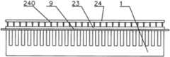
图1为本发明一种纺织品切割装置主视示意图。FIG. 1 is a schematic front view of a textile cutting device according to the present invention.
图2为本发明一种纺织品切割装置右视示意图。FIG. 2 is a schematic diagram of a right side view of a textile cutting device according to the present invention.
图3为本发明一种纺织品切割装置俯视示意图。3 is a schematic top view of a textile cutting device according to the present invention.
图4为本发明一种纺织品切割装置第一握持体主视示意图。4 is a schematic front view of a first holding body of a textile cutting device according to the present invention.
图5为本发明一种纺织品切割装置第一握持体俯视示意图。5 is a schematic top view of a first holding body of a textile cutting device according to the present invention.
图6为本发明一种纺织品切割装置第二握持体俯视示意图。6 is a schematic top view of a second holding body of a textile cutting device according to the present invention.
图7为本发明一种纺织品切割装置握持纺织品切割的示意图。FIG. 7 is a schematic diagram of a textile cutting device holding textile cutting according to the present invention.
图8为本发明一种纺织品切割装置一种增强握持力原理示意图。FIG. 8 is a schematic diagram of the principle of enhancing the gripping force of a textile cutting device according to the present invention.
图9为本发明一种纺织品切割装置带针第一握持体结构示意图。9 is a schematic structural diagram of a first holding body with needles of a textile cutting device according to the present invention.
图10为本发明一种纺织品切割装置带针握持纺织品原理示意图。FIG. 10 is a schematic diagram of the principle of a textile cutting device with needles for holding textiles according to the present invention.
图11为本发明一种纺织品切割装置带孔第二握持体示意图。11 is a schematic diagram of a second holding body with holes of a textile cutting device according to the present invention.
图12为本发明一种纺织品切割装置第二握持体侧带针握持示意图。FIG. 12 is a schematic diagram of holding a needle on the side of the second holding body of a textile cutting device according to the present invention.
图13为本发明一种纺织品切割装置第二活动针板握持示意图。Fig. 13 is a schematic diagram of holding the second movable needle plate of a textile cutting device according to the present invention.
图14为本发明一种纺织品切割装置第一活动针板握持示意图。FIG. 14 is a schematic view of holding the first movable needle plate of a textile cutting device according to the present invention.
图中:1.第一握持体 10.第一握持体基板 11.第一握持体弹性条 12.第一握持体针状物 13.带孔第一握持体 14.第一针板 140.第一针板针状物 15.第一握持体支柱 2.第二握持体 20.第二握持体基板 21.第二握持体弹性条 22.第二握持体针状物 23.带孔第二握持体 230.通孔 24.第二针板 240.第二针板针状物 25.第二握持体弹性层 30.切刀 31.刀轴 32.切刀轴带轮 33.切刀电机 40.铅锤导轨 41.切刀上下滑块 42.第二握持体上下滑块 44.切刀水平导轨 440.切刀水平导轨安装件 45.切刀水平滑块 46.切刀铅锤气缸 51.切刀移动平台 52.压紧滑块 53.压紧导杆 530.压紧弹簧 54.压紧轴座 55.压紧轴 56.切刀水平丝杠 560.丝杠螺母 561.丝杠轴承座 57.切刀水平电机 9.纺织品 91.水平机架 92.铅锤机架In the figure: 1. The
具体实施方式Detailed ways
下面结合图例给出本发明一种纺织品切割装置的几个具体实施例,这些实施例仅是对本发明的举例说明,并不构成对本发明权利要求的限制,本发明未述及之处适用于现有技术。Several specific embodiments of a textile cutting device of the present invention are given below in conjunction with the legends. These embodiments are only examples of the present invention, and do not constitute limitations to the claims of the present invention. There is technology.
本发明一种纺织品切割装置的实施例1(如图1~11所示):
一种纺织品切割装置,其包含机架、握持部件、切刀及切刀驱动装置,所述机架包括水平机架91以及与水平机架91相垂直的铅锤机架92,A textile cutting device includes a frame, a holding part, a cutter and a cutter drive device, the frame includes a
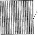
所述握持部件包含第一握持体1与第二握持体2,握持部件握持纺织品切割的示意图如图7所示,采用第一握持体1以及第二握持体2上下夹持纺织品9,如图4、5所示,第一握持体1是带有26根互相平行、凸起状长条的板状部件;如图6所示,第二握持体2是一块多根长条的镂空板,图7中刀片穿过第二握持体2的贯穿的缝隙切割纺织品9,第一握持体1上的沟槽用于通过刀片30。相当于第一握持体1及第二握持体2均具有平行、间隔排列的长条状结构用于夹持纺织品,第一握持体1及第二握持体2用于夹持纺织品的长条在纺织品的两侧面对齐,当然不排除第一握持体1采用第二握持体2结构并加厚。The holding member includes a
这种方案切割纺织品过程中经常会出现纺织品握持不够牢固,纺织品在第一握持体1及第二握持体2之间发生滑动,导致纺织品被嵌入到第一握持体1相邻两长条状结构部件之间的凹槽中。作为改进方案,为增大对纺织品的握持力,如图8所示,第一握持体1及第二握持体2与纺织品接触的面均加上小沟槽,或者第一握持体1及第二握持体2与纺织品接触的面采用摩擦系数大的材料或者柔性材料,这些方法及手段都不能杜绝纺织品在被切割过程中在第一握持体1及第二握持体2之间发生滑动的情况发生。In the process of cutting textiles with this solution, the textiles are often not held firmly enough, and the textiles slide between the
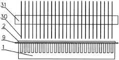
为了绝对有效地握持纺织品,改进图7中纺织品9下方的第一握持体1,将第一握持体内部植入针状物,如图9所示,在一块板状的第一握持体基板10上利用植针技术植入与第一握持体基板10相垂直、呈行列分布(26行、26列)的第一握持体针状物12,第一握持体针状物12的行、列间距6mm。第一握持体弹性条11为其上有26个通孔(孔间距6mm)的橡胶弹性条,第一握持体弹性条11宽3mm(图9中左右方向)、长153mm(图9中上下方向)、高25mm(图9中垂直于纸面的方向),将长条状的第一握持体弹性条11套在第一握持体针状物12上,第一握持体弹性条11上的每个孔内穿过一根第一握持体针状物12,第一握持体针状物12露出第一握持体基板10的高度为24mm,略低于第一握持体弹性条11的高度。本实施例中纺织品下方的第一握持体1相当于是由针板上套了26根弹性条组成,在第一握持体与第二握持体没有夹持住纺织品之前,所述第一握持体针状物12的尖端藏在第一握持体弹性条11中,不伸出第一握持体弹性条11与纺织品接触的表面。当第一握持体弹性条11与第二握持体2夹持纺织品9时,如图10所示,纺织品9被握持在第一握持体弹性条11及第二握持体2之间,给第一握持体基板10或第二握持体2向纺织品方向加压将纺织品9压紧时,第一握持体弹性条11高度方向(图10中上下方向)会被压收缩,第一握持体针状物12的尖端会伸出至第一握持体弹性条11外,并扎入纺织品9中,防止纺织品9在被切割的过程中沿第一握持体针状物12的径向移动导致切不开纺织品。图10中的第一握持体针状物12本应被第一握持体弹性条11遮挡着看不到,为了方便表示其位置,在图10中用实线表示。In order to hold the textiles absolutely effectively, the
所述第一握持体1安装在水平机架91上,第一握持体1与纺织品接触的面处于水平状态,第二握持体2通过第二握持体上下滑块42上下活动安装在铅锤导轨40上,铅锤导轨40安装在铅锤机架92上,第二握持体2在第一握持体1的上方,且具有靠近与远离第一握持体1的自由度,能运动到与第一握持体1接触,第二握持体2接触到第一握持体1时,其接触纺织品的面与第一握持体1接触纺织品的面接触、对齐。The
采用该带有针状物的握持部件握持纺织品时,即使是纺织品厚薄不匀,由于第一握持体弹性条11本身就具有可压缩性,其与第二握持体2之间压紧纺织品时基本能够将纺织品全部压住,加之第一握持体针状物12的尖端对纺织品所起到的强制性固定作用,会达到很好的握持效果。When the holding member with needles is used to hold the textile, even if the thickness of the textile is uneven, due to the compressibility of the first holding body
将纺织品切割为小方块时,可以采用图7所示主动绕其轴心旋转的切刀30一次将纺织品切割成多根条状,将纺织品水平旋转90度,在与第一次切割方向相垂直的方向再次切割便可以将纺织品切割为多块小方块。如图7所示,25片圆刀片套在切刀轴31上构成切刀,刀片之间等间距、对齐排列,刀片间距与第一握持体弹性条11间距相等,所有刀片的切削刃位于一个面上,刀片对准两个第一握持体弹性条11间距中间部位,这样切刀30一次可以将被切割纺织品切割为24条,当然不排除用单个切刀片一次切割一条切口的方式。When cutting the textile into small squares, the
所述切刀通过轴承座悬挂安装在切刀移动平台51上,安装在切刀移动平台51上的切刀电机33通过皮带以及切刀轴带轮32带动切刀30绕其刀轴轴心转动,圆刀片或六角刀片等主动旋转切割纺织品,切刀电机33作为切刀转动驱动装置的驱动部件,切刀轴承及轴承座作为切刀转动驱动装置的导向部件。The cutter is suspended and mounted on the
切刀移动平台51悬挂安装在沿切刀水平导轨44移动的切刀水平滑块45上,切刀水平导轨44通过切刀水平导轨安装件440安装在切刀上下滑块41上,丝杠螺母560安装在切刀移动平台51上,丝杠轴承座561安装在切刀水平导轨安装件440上,切刀水平导轨安装件440安装在沿铅锤导轨40上下滑动的切刀上下滑块41上,切刀水平丝杠56穿过丝杠螺母560及丝杠轴承座561,安装在切刀水平导轨安装件440上的切刀水平电机57通过皮带带动切刀水平丝杠56转动,切刀水平丝杠56转动带动切刀水平移动平台51水平运动(图2中左右方向运动),从而带动切刀水平进行切割方向运动。切刀水平电机57及切刀水平丝杠56作为切割运动驱动装置的驱动部件,切刀水平导轨44及切刀水平滑块45作为切割运动驱动装置的导向部件。The
切刀上下滑块41沿安装在铅锤机架92上的铅锤导轨40上下滑动,切刀上下滑块41位于第二握持体上下滑块42的上方,切刀位于第二握持体2的上方,安装在铅锤机架92上的切刀铅锤气缸46的气缸杆连接到切刀水平导轨安装件440上,切刀铅锤气缸46作为切刀进给驱动装置的(切刀进给方向为图1~2中上下方向)驱动部件,切刀上下滑块41及铅锤导轨40作为切刀进给驱动装置的导向部件。The upper and
籍由以上机构,需要切碎纺织品时,将纺织品放在第一握持体1的上面,切刀铅锤气缸46驱动切刀上下滑块41带动切刀水平导轨以及切刀沿铅锤导轨40向下(图1、2中)进给运动,第二握持体上下滑块42与切刀上下滑块41之间安装一根压缩弹簧,则压缩弹簧将第二握持体2压向第一握持体1并与之握持住纺织品,当然也可以采用单独的气缸或者电机驱动第二握持体2压向第一握持体1,由于第一握持体1受压,第一握持体弹性条11中的第一握持体针状物12便会伸出第一握持体弹性条11刺入纺织品中,纺织品便被第一握持体及第二握持体握持牢固。Due to the above mechanism, when the textile needs to be chopped, the textile is placed on the top of the
切刀30继续下行并由切刀电机33带动旋转,刀片通过第二握持体2长条状结构部件通透的缝隙开始切割纺织品,切刀水平电机57通过切刀水平丝杠56驱动切刀沿图2中左右方向移动,实现切割运动,切割完成后切刀铅锤气缸46将切刀提起,第一握持体弹性条11中的第一握持体针状物12便会缩回至第一握持体弹性条11内,将纺织品旋转90度后放在第一握持体1的上面,再重复一次切割,纺织品便被切成了小方块。The
尽管本实施例中每根第一握持体弹性条11中含有一排第一握持体针状物12,但是不排除采用2排及多排,每排第一握持体针状物12中相邻两根针状物的间距是6mm,刀片的间距为6mm,第一握持体以及第二握持体用于握持纺织品的长条状部件的宽度是3mm、间隔的凹槽是3mm,这样切成的纺织品碎片边长为6mm,但是不排除其它间距。同样,不排除采用其它排、列数量的长条状部件。例如,每排第一握持体针状物12中相邻针状物之间的间距小一些(例如3mm),更利于纺织品第一次切割成条状后再垂直方向进行第二次切割时对纺织品的良好握持,因为第一次切割完后条状纺织品的条宽为6mm,每排第一握持体针状物12中针状物间距为3mm的话,沿与第一次切割时方向垂直的方向进行第二次切割握持时,每条6mm宽纺织品长条均能保证能有针状物刺入。Although in this embodiment, each first holding body
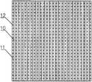
为防止第一握持体针状物12刺透纺织品后扎到第二握持体2上损伤第一握持体针状物12的尖端,可以将图10中的第二握持体2替换为图11所示的带孔第二握持体23,带孔第二握持体23相当于在第二握持体2上开了很多通孔,其上分布的通孔230与第一握持体针状物12对齐,第一握持体针状物12刺透纺织品后可以伸入通孔230中,不仅保护了第一握持体针状物12的尖端,由于第一握持体针状物完全穿透纺织品9,能起到更强的固定作用。In order to prevent the
尽管本实施例中第一握持体1固定安装在水平机架91上,第二握持体向下运动与第一握持体握持纺织品,切刀驱动装置含有驱动切刀绕其轴心转动的转动驱动装置、驱动切刀沿进刀方向(握持体接触纺织品的面的法线方向)移动的进给驱动装置以及驱动切刀沿切割纺织品方向(即握持体长条状结构部件的长度方向)移动的切割驱动装置。其实,只要是第一握持体、第二握持体与切刀三者中至少有两者在第一握持体与第二握持体接触面的法线方向(图1~2中上、下方向)上具有运动自由度即可,因此,在第一握持体与第二握持体接触面的法线方向上,除了本实施例中的第二握持体与切刀动、第一握持体不动的方案之外,也可以采用第一握持体与切刀动、第二握持体不动的方案,还可以采用第一握持体及第二握持体动、切刀不动的方案,甚至可以采用第一握持体、第二握持体、切刀三者都动的方案。第一握持体1动可以采用不同方式,例如,第一握持体1通过三杆气缸活动升降安装在水平机架91上并由三杆气缸驱动升降运动,与第二握持体握持纺织品。Although the
对于切割运动,其实只要是握持部件与切刀在握持体长条状结构部件长度方向具有相对运动自由度即可,因此,如果握持部件在握持体长条状结构部件长度方向具有运动自由度的话,切刀在握持体长条状结构部件长度方向可以固定不动。For the cutting motion, in fact, as long as the gripping member and the cutter have relative freedom of movement in the length direction of the elongated structural member of the gripping body, if the gripping member has freedom of movement in the lengthwise direction of the elongated structural member of the gripping body If the degree is high, the cutter can be fixed in the length direction of the long strip-shaped structural member of the grip body.
这些都是机械领域的常识性替换,通过变换安装方式、方向等可以用多种方式实现运动的配合。These are all common sense replacements in the mechanical field. By changing the installation method, direction, etc., the coordination of motion can be realized in various ways.
本发明一种纺织品切割装置的实施例2(如图1~3所示):
实施例1中需要较大的压紧力才能使第一握持体弹性条11产生足够的压缩变形量使第一握持针状物12露出第一握持体弹性条11,因此,为了给纺织品施加足够的压力,第二握持体2需要具有比较大的刚度,实施例1中第二握持体2是一个2mm厚的碳纤维复合板(当然可以用其它厚度的玻纤板、弹簧钢板等其它板)加工而成,通过其端部(图2中的右端)施加压力第二握持体2会弯曲,无法保证整个握持范围内的均匀加压,即使将第二握持体2的厚度加大,或者将加压的压缩弹簧加压点分布在第二握持体的两端,也很难在端部施加使第一握持体弹性条11产生足够变形量的力,特别是第一握持体弹性条11的中部变形量会不够,并且,切刀需要通过第二握持体的缝隙切割纺织品,第二握持体的厚度不宜太大,否则刀片的直径就需要增大,因此,第二握持体的厚度不宜厚。In
为了解决该问题,本实施例为所述纺织品切割装置增加压紧装置,用于在切刀切割纺织品时将第二握持体2局部压紧在第一握持体上1的纺织品上。In order to solve this problem, this embodiment adds a pressing device to the textile cutting device, which is used to partially press the
将实施例1中第二握持体上下滑块42与切刀上下滑块41之间安装的驱动第二握持体上下活动的压缩弹簧去掉,将第二握持体上下滑块42通过一根绳吊挂在切刀上下滑块41上。Remove the compression springs installed between the upper and
压紧装置用与刀轴31平行的两根压紧轴55在靠近第二握持体2的切刀两侧压在第二握持体2上方,压紧轴55与刀轴31平行,压紧轴55两端分别穿过两个压紧轴座54,每个压紧轴座54两端安装两根压紧导杆53,压紧导杆53穿过安装在切刀移动平台51上的压紧滑块52,在切刀移动平台51与压紧轴座54之间的压紧导杆53外套压紧弹簧530,相当于两根压紧轴55通过四根压紧导杆53可上下滑动的悬挂安装在切刀移动平台51下方。The pressing device uses two
当切刀铅锤气缸46驱动切刀30向下(图1、2中)进给运动时,第二握持体上下滑块42下滑将第二握持体2放在第一握持体1上的纺织品上,切刀继续下行,悬挂在切刀下的压紧轴55会落在第二握持体2上,随着切刀继续下行,压紧弹簧530受压缩,使压紧轴55压紧第二握持体,第二握持体2是一个2mm厚的碳纤维复合板,其具有一定的刚度,同时又能局部弯曲,压紧轴55压紧第二握持体2使其局部弯曲,由于两根压紧轴55间距与刀片外径相近,仅在切刀切割纺织品的局部压紧纺织品,这样只需要较小的压紧力就能在切割位置附近使第一握持体弹性条11达到足够的变形量,从而使第一握持体针状物12刺入纺织品9中。压紧轴55随切刀移动而移动,确保整个切割过程中切割位置附近的纺织品均能被有效地握持。切割完成后不再加压时,第一握持体针状物12会重新缩回至第一握持体弹性条11的内部,不会挂住纺织品,便于自动将切碎的纺织品取走或清理掉。When the cutter plumb
当然不排除采用气缸等独立驱动部件压紧轴55,例如用安装在切刀移动平台51上的气缸向下驱动压紧轴55,压紧力取决于气缸的缸径及气压,其实相当于气动弹簧。或者压紧装置采用一端安装在切刀移动平台51下方的弯曲的弹簧片,弹簧片的另一端压向下伸出至低于刀片,当切刀向第二握持体移动时,弹簧片伸出端先接触第二握持体以施加压力,随着切刀继续向第二握持体移动,靠弹簧片的变形增大压力。或者还可以用重力压紧,例如在切刀移动平台51下方用上下导向机构上下滑动悬挂重物,用重物的重力作为压紧力,相当于去掉图1~2中的压紧弹簧530,在压紧轴55上端增加配重。Of course, it is not excluded to use an independent driving component such as a cylinder to press the
本发明一种纺织品切割装置的实施例3(如图1~3、12所示):Embodiment 3 of a textile cutting device of the present invention (as shown in Figures 1-3, 12):
与实施例2不同,本实施例针状物安装在了第二握持体侧,如图12所示,相当于对图7中的第二握持体2进行了改造。在第二握持体基板20下方植入尖头向下的第二握持体针状物22,并将第二握持体弹性条21套在第二握持体针状物22上,第二握持体弹性条21结构与第一握持体弹性条11相似,只是高度低于第一握持体弹性条11,同样,不施加外力时,第二握持体针状物22的尖端不会外露在第二握持体弹性条21外。Different from the second embodiment, the needle-shaped object in this embodiment is installed on the side of the second holding body, as shown in FIG. 12 , which is equivalent to the modification of the
当第二握持体弹性条21与第一握持体1上凸起的长条状部件共同握持纺织品9时,通过向下压第二握持体基板20,第二握持体弹性条21被压缩,其中的第二握持体针状物22伸出第二握持体弹性条21扎入纺织品9内,限制纺织品水平方向位移。切割完成后,去除施加在第二握持体基板20上的力,第二握持体弹性条21恢复至原高度,第二握持体弹性条21缩回至第二握持体弹性条21内,特别适用于自动制样时自动将切开的布样取走。When the second holding body
为了防止第二握持体针状物22向下穿透纺织品9后扎到第一握持体1上损伤第二握持体针状物22的尖端,或者损伤第一握持体1的上表面,可以在将第一握持体1与纺织品接触处由硅胶、橡胶等软弹性材料制成,或者贴一层硅胶、橡胶等材料。In order to prevent the
图12中的第二握持体针状物22本应被第二握持体弹性条21遮挡着看不到,为了方便表示其位置,在图12中用实线画出。The
本发明一种纺织品切割装置的实施例4(如图13所示):Embodiment 4 of a textile cutting device of the present invention (as shown in Figure 13 ):
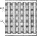
本实施例中纺织品9下方的第一握持体1与实施例2中相同,纺织品上方设置带孔第二握持体23以及第二针板24。所述第二针板24与第二握持体2结构相同,也是一块多根长条的镂空板,不同之处在于第二针板24下方安装有尖端向下的26行、26列第二针板针状物240,第二针板针状物240与带孔第二握持体23上的通孔一一对齐。第二针板24与带孔第二握持体23之间的部分第二针板针状物240外侧套压缩弹簧,当第二针板24不受指向第一握持体1方向的压力时,弹簧将第二针板24顶起,第二针板针状物240不会向下伸出带孔第二握持体23的通孔230,当需要握持纺织品9时,带孔第二握持体23与第一握持体1夹持住纺织品9,第二针板24受压带动第二针板针状物240向下运动穿过带孔第二握持体23的通孔230后刺入纺织品9中,起到定位纺织品的作用。In this embodiment, the
该实施例中带孔第二握持体23以及第一握持体1与纺织品接触的面均可以采用非软弹性材料,但是,由于纺织品不完全平整,即使第一次切割时纺织品是平整的,切割成条后再次沿垂直方向第二次切割时也会不再平整,例如可能会有卷边等现象,因此,优选还是纺织品9两侧的握持体中与纺织品接触的面至少有一面采用软弹性材料,利用软弹性材料夹持纺织品利于切割纺织品过程中对局部纤维的有效握持,特别是对于本身厚度就不匀的纺织品,例如镂空织物、比较稀疏的织物等。针状物起到强握持作用,软弹性材料变形握持起到辅助握持作用,两种作用相辅相成。In this embodiment, the
不排除第二针板24的驱动采用气缸等独立驱动。It is not excluded that the driving of the
本发明一种纺织品切割装置的实施例5(如图14所示):Embodiment 5 of a textile cutting device of the present invention (as shown in FIG. 14 ):
本实施例中纺织品9上方采用第二握持体2握持纺织品9,纺织品9下方设置带孔第一握持体13以及第一针板14。图14中的带孔第一握持体13相当于是带有多个通孔(通孔轴线方向在图14中是上下方向)的第一握持体1,由注塑工艺制备而成,或者用金属铸造或者机加工的方式加工。所述第一针板14是一块板,其上安装有尖端向上的第一针板针状物140,第一针板针状物140与带孔第一握持体13上的通孔一一对齐。为了提高握持效果,第二握持体2下面贴有第二握持体弹性层25,第二握持体弹性层25为聚氨酯微发泡板制成的与第二握持体2相同形状的部件,粘贴在第二握持体2的下方。第一针板14与带孔第一握持体13之间安装有可压缩的硅胶弹垫,使带孔第一握持体13不受第二握持体向下压力时第一针板针状物140不向上伸出带孔第一握持体13上表面。In this embodiment, a
当需要握持纺织品9时,带孔第一握持体13上的长条状部件的顶面与第二握持体2下面的第二握持体弹性层25夹持住纺织品9,第二握持体2被压紧装置向下压时,使带孔第一握持体13向下移动,第一针板针状物140经带孔第一握持体13的通孔刺入纺织品9中,起到定位纺织品的作用。图14中的第一针板针状物140被第带孔第一握持体13遮挡的部分应该是看不到,为了方便表示其位置,在图中用实线画出。When the
当然不排除采用独立的气缸等驱动部件驱动第一针板14带动第一针板针状物140向上穿过带孔第一握持体13的通孔后刺入纺织品9中。Of course, it is not ruled out that the
所有实施例中的驱动装置均可以用具有相同功能的常用部件及机构替换,例如气缸驱动的移动可以改为直线电机、旋转电机加丝杆、电机加凸轮顶杆、电磁铁等驱动,导向可以采用光轴、滑块或线性导轨等导向等,这些均属于本领域的常识,不再赘述。本发明不限于上文讨论的实施例,本领域技术人员可根据本发明推理出其它变体形式,这些变体形式也属于本发明的主题。The driving devices in all the embodiments can be replaced with common components and mechanisms with the same functions. For example, the movement driven by the cylinder can be changed to a linear motor, a rotary motor plus a screw, a motor plus a cam ejector, an electromagnet, etc., and the guide can be Guides such as optical axes, sliders or linear guides are used, which are common knowledge in the field and will not be repeated here. The present invention is not limited to the embodiments discussed above, and those skilled in the art can deduce other variants according to the present invention, which also belong to the subject matter of the present invention.
Claims (7)
Priority Applications (1)
| Application Number | Priority Date | Filing Date | Title |
|---|---|---|---|
| CN202110782276.XACN113400386B (en) | 2021-07-12 | 2021-07-12 | Textile cutting device |
Applications Claiming Priority (1)
| Application Number | Priority Date | Filing Date | Title |
|---|---|---|---|
| CN202110782276.XACN113400386B (en) | 2021-07-12 | 2021-07-12 | Textile cutting device |
Publications (2)
| Publication Number | Publication Date |
|---|---|
| CN113400386A CN113400386A (en) | 2021-09-17 |
| CN113400386Btrue CN113400386B (en) | 2022-08-02 |
Family
ID=77685885
Family Applications (1)
| Application Number | Title | Priority Date | Filing Date |
|---|---|---|---|
| CN202110782276.XAActiveCN113400386B (en) | 2021-07-12 | 2021-07-12 | Textile cutting device |
Country Status (1)
| Country | Link |
|---|---|
| CN (1) | CN113400386B (en) |
Family Cites Families (6)
| Publication number | Priority date | Publication date | Assignee | Title |
|---|---|---|---|---|
| ATE128405T1 (en)* | 1990-02-20 | 1995-10-15 | Procter & Gamble | OPEN CAPILLARY CHANNELS STRUCTURE, METHOD FOR MAKING SAME AND EXTRUSION NOZZLE FOR USE THEREIN. |
| US6823763B1 (en)* | 1997-05-30 | 2004-11-30 | Sara Lee Corporation | Automated garment piece cutter |
| CN104647457B (en)* | 2015-03-19 | 2016-04-20 | 河北工业大学 | A kind of cutting clamping device |
| CN110109421B (en)* | 2018-02-01 | 2023-03-14 | 天津工业大学 | Path planning method for acupuncture robot |
| CN111452113A (en)* | 2019-01-18 | 2020-07-28 | 天津工业大学 | Textile chopping method and textile chopping device applying same |
| CN210458724U (en)* | 2019-07-09 | 2020-05-05 | 界首市名扬针纺科技有限公司 | Cutting device is used in cotton production of regeneration |
- 2021
- 2021-07-12CNCN202110782276.XApatent/CN113400386B/enactiveActive
Also Published As
| Publication number | Publication date |
|---|---|
| CN113400386A (en) | 2021-09-17 |
Similar Documents
| Publication | Publication Date | Title |
|---|---|---|
| CN111452113A (en) | Textile chopping method and textile chopping device applying same | |
| CN102489577B (en) | Automatic deep-draw device for metal sheets | |
| CN109866497B (en) | Film stripping and removing device and method | |
| US7469622B2 (en) | Paper cutting machine having movable rest | |
| CN108312367A (en) | A kind of plate cutting machinery | |
| JP5031467B2 (en) | Finger joiner | |
| CN113400386B (en) | Textile cutting device | |
| KR20200037296A (en) | Film cutting device with linear actuator | |
| CN209520938U (en) | A textile shredding device | |
| CN109849494B (en) | Film stripping mechanism and stripping device | |
| JP2003062711A (en) | Automatic drilling device for u-rib | |
| CN210210140U (en) | Magnetic material inside diameter slicer clamping tool | |
| KR102036538B1 (en) | Apparatus for cutting round bar | |
| CN113601592B (en) | A textile holding method and a textile holding component | |
| CN216804585U (en) | Waste cleaning machine | |
| US1468705A (en) | Article holder for slicing machines | |
| CN217084548U (en) | Rubber alcohol friction resistance testing machine | |
| CN213714925U (en) | Tensile tension detection device for novel biodegradable fiber cloth | |
| JP2018119836A (en) | Thin slice preparation device | |
| KR20180032308A (en) | Material fixing apparatus | |
| CN212030948U (en) | A tissue sectioning device for pathologists | |
| CN210308094U (en) | Biological tissue slicer | |
| CN223395424U (en) | A device for fixing columnar pine wood cutting boards | |
| CN216732081U (en) | Abrasive paper cutting and positioning device | |
| CN222837853U (en) | Material taking device for extracting surface sweetener of tipping paper |
Legal Events
| Date | Code | Title | Description |
|---|---|---|---|
| PB01 | Publication | ||
| PB01 | Publication | ||
| SE01 | Entry into force of request for substantive examination | ||
| SE01 | Entry into force of request for substantive examination | ||
| GR01 | Patent grant | ||
| GR01 | Patent grant |