CN113397616B - a surgical instrument - Google Patents
a surgical instrumentDownload PDFInfo
- Publication number
- CN113397616B CN113397616BCN202110865511.XACN202110865511ACN113397616BCN 113397616 BCN113397616 BCN 113397616BCN 202110865511 ACN202110865511 ACN 202110865511ACN 113397616 BCN113397616 BCN 113397616B
- Authority
- CN
- China
- Prior art keywords
- loading unit
- piece
- sliding
- trigger
- surgical instrument
- Prior art date
- Legal status (The legal status is an assumption and is not a legal conclusion. Google has not performed a legal analysis and makes no representation as to the accuracy of the status listed.)
- Active
Links
Images


Classifications
- A—HUMAN NECESSITIES
- A61—MEDICAL OR VETERINARY SCIENCE; HYGIENE
- A61B—DIAGNOSIS; SURGERY; IDENTIFICATION
- A61B17/00—Surgical instruments, devices or methods
- A61B17/00234—Surgical instruments, devices or methods for minimally invasive surgery
- A—HUMAN NECESSITIES
- A61—MEDICAL OR VETERINARY SCIENCE; HYGIENE
- A61B—DIAGNOSIS; SURGERY; IDENTIFICATION
- A61B17/00—Surgical instruments, devices or methods
- A61B17/11—Surgical instruments, devices or methods for performing anastomosis; Buttons for anastomosis
- A61B17/115—Staplers for performing anastomosis, e.g. in a single operation
- A—HUMAN NECESSITIES
- A61—MEDICAL OR VETERINARY SCIENCE; HYGIENE
- A61B—DIAGNOSIS; SURGERY; IDENTIFICATION
- A61B17/00—Surgical instruments, devices or methods
- A61B17/068—Surgical staplers, e.g. containing multiple staples or clamps
- A61B17/072—Surgical staplers, e.g. containing multiple staples or clamps for applying a row of staples in a single action, e.g. the staples being applied simultaneously
- A61B17/07207—Surgical staplers, e.g. containing multiple staples or clamps for applying a row of staples in a single action, e.g. the staples being applied simultaneously the staples being applied sequentially
- A—HUMAN NECESSITIES
- A61—MEDICAL OR VETERINARY SCIENCE; HYGIENE
- A61B—DIAGNOSIS; SURGERY; IDENTIFICATION
- A61B90/00—Instruments, implements or accessories specially adapted for surgery or diagnosis and not covered by any of the groups A61B1/00 - A61B50/00, e.g. for luxation treatment or for protecting wound edges
- A61B90/08—Accessories or related features not otherwise provided for
- A—HUMAN NECESSITIES
- A61—MEDICAL OR VETERINARY SCIENCE; HYGIENE
- A61B—DIAGNOSIS; SURGERY; IDENTIFICATION
- A61B90/00—Instruments, implements or accessories specially adapted for surgery or diagnosis and not covered by any of the groups A61B1/00 - A61B50/00, e.g. for luxation treatment or for protecting wound edges
- A61B90/90—Identification means for patients or instruments, e.g. tags
- A—HUMAN NECESSITIES
- A61—MEDICAL OR VETERINARY SCIENCE; HYGIENE
- A61B—DIAGNOSIS; SURGERY; IDENTIFICATION
- A61B17/00—Surgical instruments, devices or methods
- A61B2017/00017—Electrical control of surgical instruments
- A—HUMAN NECESSITIES
- A61—MEDICAL OR VETERINARY SCIENCE; HYGIENE
- A61B—DIAGNOSIS; SURGERY; IDENTIFICATION
- A61B17/00—Surgical instruments, devices or methods
- A61B17/00234—Surgical instruments, devices or methods for minimally invasive surgery
- A61B2017/00353—Surgical instruments, devices or methods for minimally invasive surgery one mechanical instrument performing multiple functions, e.g. cutting and grasping
- A—HUMAN NECESSITIES
- A61—MEDICAL OR VETERINARY SCIENCE; HYGIENE
- A61B—DIAGNOSIS; SURGERY; IDENTIFICATION
- A61B17/00—Surgical instruments, devices or methods
- A61B2017/00367—Details of actuation of instruments, e.g. relations between pushing buttons, or the like, and activation of the tool, working tip, or the like
- A61B2017/00398—Details of actuation of instruments, e.g. relations between pushing buttons, or the like, and activation of the tool, working tip, or the like using powered actuators, e.g. stepper motors, solenoids
- A—HUMAN NECESSITIES
- A61—MEDICAL OR VETERINARY SCIENCE; HYGIENE
- A61B—DIAGNOSIS; SURGERY; IDENTIFICATION
- A61B17/00—Surgical instruments, devices or methods
- A61B2017/0046—Surgical instruments, devices or methods with a releasable handle; with handle and operating part separable
- A—HUMAN NECESSITIES
- A61—MEDICAL OR VETERINARY SCIENCE; HYGIENE
- A61B—DIAGNOSIS; SURGERY; IDENTIFICATION
- A61B17/00—Surgical instruments, devices or methods
- A61B2017/0046—Surgical instruments, devices or methods with a releasable handle; with handle and operating part separable
- A61B2017/00473—Distal part, e.g. tip or head
- A—HUMAN NECESSITIES
- A61—MEDICAL OR VETERINARY SCIENCE; HYGIENE
- A61B—DIAGNOSIS; SURGERY; IDENTIFICATION
- A61B17/00—Surgical instruments, devices or methods
- A61B2017/00477—Coupling
- A61B2017/00482—Coupling with a code
- A—HUMAN NECESSITIES
- A61—MEDICAL OR VETERINARY SCIENCE; HYGIENE
- A61B—DIAGNOSIS; SURGERY; IDENTIFICATION
- A61B17/00—Surgical instruments, devices or methods
- A61B2017/00982—General structural features
- A—HUMAN NECESSITIES
- A61—MEDICAL OR VETERINARY SCIENCE; HYGIENE
- A61B—DIAGNOSIS; SURGERY; IDENTIFICATION
- A61B17/00—Surgical instruments, devices or methods
- A61B17/068—Surgical staplers, e.g. containing multiple staples or clamps
- A61B17/072—Surgical staplers, e.g. containing multiple staples or clamps for applying a row of staples in a single action, e.g. the staples being applied simultaneously
- A61B2017/07214—Stapler heads
- A61B2017/07285—Stapler heads characterised by its cutter
- A—HUMAN NECESSITIES
- A61—MEDICAL OR VETERINARY SCIENCE; HYGIENE
- A61B—DIAGNOSIS; SURGERY; IDENTIFICATION
- A61B90/00—Instruments, implements or accessories specially adapted for surgery or diagnosis and not covered by any of the groups A61B1/00 - A61B50/00, e.g. for luxation treatment or for protecting wound edges
- A61B90/08—Accessories or related features not otherwise provided for
- A61B2090/0803—Counting the number of times an instrument is used
- A—HUMAN NECESSITIES
- A61—MEDICAL OR VETERINARY SCIENCE; HYGIENE
- A61B—DIAGNOSIS; SURGERY; IDENTIFICATION
- A61B90/00—Instruments, implements or accessories specially adapted for surgery or diagnosis and not covered by any of the groups A61B1/00 - A61B50/00, e.g. for luxation treatment or for protecting wound edges
- A61B90/08—Accessories or related features not otherwise provided for
- A61B2090/0807—Indication means
- A61B2090/0808—Indication means for indicating correct assembly of components, e.g. of the surgical apparatus
- A—HUMAN NECESSITIES
- A61—MEDICAL OR VETERINARY SCIENCE; HYGIENE
- A61B—DIAGNOSIS; SURGERY; IDENTIFICATION
- A61B90/00—Instruments, implements or accessories specially adapted for surgery or diagnosis and not covered by any of the groups A61B1/00 - A61B50/00, e.g. for luxation treatment or for protecting wound edges
- A61B90/08—Accessories or related features not otherwise provided for
- A61B2090/0807—Indication means
- A61B2090/0811—Indication means for the position of a particular part of an instrument with respect to the rest of the instrument, e.g. position of the anvil of a stapling instrument
- A—HUMAN NECESSITIES
- A61—MEDICAL OR VETERINARY SCIENCE; HYGIENE
- A61B—DIAGNOSIS; SURGERY; IDENTIFICATION
- A61B90/00—Instruments, implements or accessories specially adapted for surgery or diagnosis and not covered by any of the groups A61B1/00 - A61B50/00, e.g. for luxation treatment or for protecting wound edges
- A61B90/90—Identification means for patients or instruments, e.g. tags
- A61B90/98—Identification means for patients or instruments, e.g. tags using electromagnetic means, e.g. transponders
Landscapes
- Health & Medical Sciences (AREA)
- Surgery (AREA)
- Life Sciences & Earth Sciences (AREA)
- Heart & Thoracic Surgery (AREA)
- Engineering & Computer Science (AREA)
- Biomedical Technology (AREA)
- Nuclear Medicine, Radiotherapy & Molecular Imaging (AREA)
- Medical Informatics (AREA)
- Molecular Biology (AREA)
- Animal Behavior & Ethology (AREA)
- General Health & Medical Sciences (AREA)
- Public Health (AREA)
- Veterinary Medicine (AREA)
- Pathology (AREA)
- Oral & Maxillofacial Surgery (AREA)
- Surgical Instruments (AREA)
Abstract
Description
Translated fromChinese技术领域technical field
本发明涉及手术器械领域,特别涉及一种能够进行装载单元类型识别的外科器械。The invention relates to the field of surgical instruments, in particular to a surgical instrument capable of identifying the type of a loading unit.
背景技术Background technique
线性夹持、切割和吻合外科器械可以在手术操作中使用以切除组织。传统的线性夹持、切割和吻合的外科器械包括装载单元、手柄组件。装载单元为外科器械的执行器,其用于夹持在要被切割/吻合的组织。由于一台手术中,手柄组件是可多次使用的,而装载单元则是一次性的,因此,通常装载单元可拆卸地安装在手柄组件上,根据不同的情况更换对应地装载单元。不同类型的装载单元所需的驱动是不同的,在更换不同的装载单元时则需要将装载单元的相关信息(例如装载单元的类型)传送至手术器械的手柄组件上的控制单元上,进而根据装载单元的类型选择对应的驱动来使装载单元执行操作,以避免发生医疗事故。Linear gripping, cutting and stapling surgical instruments can be used in surgical procedures to excise tissue. Traditional linear clamping, cutting and stapling surgical instruments include a loading unit, handle assembly. The loading unit is the actuator of the surgical instrument, which is used to hold the tissue to be cut/stapled. In one operation, the handle assembly can be used multiple times, while the loading unit is disposable. Therefore, the loading unit is usually detachably installed on the handle assembly, and the corresponding loading unit can be replaced according to different conditions. Different types of loading units require different drives. When changing different loading units, the relevant information of the loading unit (such as the type of loading unit) needs to be transmitted to the control unit on the handle assembly of the surgical instrument, and then according to the The type of the loading unit selects the corresponding drive to make the loading unit perform operations to avoid medical accidents.
现有的外科器械通常设置识别单元以区分不同类型的装载单元。现有识别单元通常采用RFID扫描识别的方式,这种方式中,需要在装载单元侧附带一个RFID芯片,手柄部分则设置读取装置。使用时,操作人员将装载单元附带的RFID芯片贴近读取装置进行扫描后,再将装载单元插接于手柄部内,控制单元则根据读取装置读取的信息获得装载单元的类型信息。这种识别方式需要在插接前进行RFID扫描,增加了操作步骤,不够方便;同时,若扫描I型装载单元后,误将II型装载单元插接于手柄部上时,控制单元此时则并不能判断装载单元的类型错误。可见,这种方式还具有误判的风险。Existing surgical instruments are often provided with identification units to distinguish different types of loading units. The existing identification unit usually adopts the RFID scanning identification method. In this method, an RFID chip needs to be attached to the side of the loading unit, and the handle part is provided with a reading device. When in use, the operator scans the RFID chip attached to the loading unit close to the reading device, then inserts the loading unit into the handle, and the control unit obtains the type information of the loading unit according to the information read by the reading device. This identification method requires RFID scanning before insertion, which increases the operation steps and is inconvenient; at the same time, if the type II loading unit is mistakenly inserted into the handle part after scanning the type I loading unit, the control unit will It is not possible to determine the wrong type of load unit. It can be seen that this method also has the risk of misjudgment.
发明内容SUMMARY OF THE INVENTION
本发明要解决的技术问题是提供一种操作方便且误判风险较低的用于线性夹持、切割和吻合的外科器械。The technical problem to be solved by the present invention is to provide a surgical instrument for linear clamping, cutting and anastomosis that is easy to operate and has a low risk of misjudgment.
针对上述技术问题,本发明提供如下技术方案:For the above-mentioned technical problems, the present invention provides the following technical solutions:
一种外科器械,包括可适配不同类型装载单元的手柄组件,所述手柄组件包括手柄部和细长体组件,所述细长体组件设有装载单元类型识别部,包括:第一滑动件,滑动连接于所述细长体组件的外壳内,所述第一滑动件用于与装载单元配合,不同类型的装载单元安装时触发所述第一滑动件滑动至不同的目标位置;第一触发件,设置于所述第一滑动件上,随所述第一滑动件移动至不同目标位置;第一电路板,固定连接于所述细长体组件的外壳内,所述第一电路板沿所述第一滑动件的滑动方向间隔设置至少两个第一响应件,每个所述第一响应件用于与所述第一触发件配合以打开或切断一个第一电支路,其中,每个所述第一电支路上的负载值不同;控制器,配置为根据所述第一电路板的反馈信号确定所述装载单元的类型。A surgical instrument includes a handle assembly that can be adapted to different types of loading units, the handle assembly includes a handle portion and an elongated body assembly, the elongated body assembly is provided with a loading unit type identification portion, including: a first sliding member , slidably connected to the casing of the elongated body assembly, the first sliding piece is used to cooperate with the loading unit, and the first sliding piece is triggered to slide to different target positions when different types of loading units are installed; a trigger member, which is arranged on the first sliding member and moves to different target positions with the first sliding member; a first circuit board is fixedly connected to the casing of the elongated body assembly, the first circuit board At least two first response members are arranged at intervals along the sliding direction of the first sliding member, each of the first response members is used to cooperate with the first trigger member to open or cut off a first electrical branch, wherein , the load value on each of the first circuit branches is different; the controller is configured to determine the type of the loading unit according to the feedback signal of the first circuit board.
本发明的部分实施方式中,所述第一触发件与所述第一响应件配合时接通所述第一电支路,所述第一触发件与所述第一响应件为面接触或线接触。In some embodiments of the present invention, the first electrical branch is turned on when the first trigger member is matched with the first response member, and the first trigger member and the first response member are in surface contact or line contact.
本发明的部分实施方式中,所述第一响应件为设置于所述第一电路板上的导电触片,所述第一触发件为弹性导电插片,所述第一触发件一端连接于所述第一滑动件上,另一端抵接于所述第一电路板上,所述第一滑动件带动所述弹性导电插片滑动至与所述导电触片接触时,将所述导电触片所在的第一电支路连通。In some embodiments of the present invention, the first response member is a conductive contact piece disposed on the first circuit board, the first trigger member is an elastic conductive insert, and one end of the first trigger member is connected to a On the first sliding piece, the other end abuts on the first circuit board, and when the first sliding piece drives the elastic conductive insert to slide to contact with the conductive contact piece, the conductive contact The first electrical branch where the chip is located is connected.
本发明的部分实施方式中,所述第一触发件与所述第一响应件配合时切断所述第一电支路,所述第一触发件的长度配置成与相邻所述第一响应件之间的间距匹配,以使其移动至目标位置处时切断其中一个所述第一电支路。In some embodiments of the present invention, the first electrical branch is cut off when the first trigger member cooperates with the first response member, and the length of the first trigger member is configured to be connected to the adjacent first response member. The spacing between the pieces is matched to cut off one of the first electrical branches when it moves to the target position.
本发明的部分实施方式中,所述第一触发件与所述第一响应件配合时切断所述第一电支路,所述第一触发件的长度配置成与相邻所述第一响应件之间的间距匹配,以使其移动至目标位置处时切断多个所述第一电支路。In some embodiments of the present invention, the first electrical branch is cut off when the first trigger member cooperates with the first response member, and the length of the first trigger member is configured to be connected to the adjacent first response member. The spacing between the pieces is matched so as to cut off the plurality of said first electrical branches when it is moved to the target position.
本发明的部分实施方式中,所述第一响应件包括互相抵接的两个弹性导电触片,两个所述弹性导电触片电连接并形成一个所述第一电支路;所述第一触发件为设置于所述第一滑动件上的绝缘凸起,所述第一滑动件带动所述绝缘凸起滑动至两个所述弹性导电触片之间时,将所述两个弹性导电触片所在的第一电支路切断。In some embodiments of the present invention, the first response member includes two elastic conductive contact pieces abutting against each other, and the two elastic conductive contact pieces are electrically connected to form one of the first electrical branches; the first electrical branch; A trigger is an insulating protrusion disposed on the first sliding element. When the first sliding element drives the insulating protrusion to slide between the two elastic conductive contact pieces, the two elastic The first electrical branch where the conductive contacts are located is cut off.
本发明的部分实施方式中,所述细长体组件的外壳与所述第一滑动件之间设有第一复位件,所述第一复位件向所述第一滑动件施加朝向远端的作用力。In some embodiments of the present invention, a first reset member is provided between the outer casing of the elongated body assembly and the first sliding member, and the first reset member applies a distal-direction to the first sliding member. force.
本发明的部分实施方式中,所述细长体组件的外壳内设有支撑架,所述支撑架上设有滑槽,所述第一电路板固定连接于所述滑槽底部,所述第一滑动件滑动连接于所述滑槽上,所述第一复位件位于所述滑槽与所述第一滑动件之间。In some embodiments of the present invention, a support frame is provided in the casing of the elongated body assembly, a chute is provided on the support frame, the first circuit board is fixedly connected to the bottom of the chute, and the first circuit board is fixedly connected to the bottom of the chute. A sliding member is slidably connected to the sliding groove, and the first restoring member is located between the sliding groove and the first sliding member.
本发明的部分实施方式中,还包括指示单元,所述指示单元用于根据控制器的信号发出指示所述装载单元类型的第一指示信号。In some embodiments of the present invention, an indicating unit is further included, and the indicating unit is configured to issue a first indicating signal indicating the type of the loading unit according to a signal of the controller.
本发明的部分实施方式中,所述装载单元的近侧设置有识别特征部,所述识别特征部包括与装载单元类型识别部配合的识别作用面,识别作用面的位置与装载单元的类型匹配。In some embodiments of the present invention, an identification feature is provided on the proximal side of the loading unit, the identification feature includes an identification action surface that cooperates with the loading unit type identification portion, and the position of the identification action surface matches the type of loading unit .
本发明的部分实施方式中,还包括装载单元安装到位识别部,包括:第二滑动件与第三滑动件,分别滑动连接于所述细长体组件的外壳内,所述第二滑动件用于与装载单元的旋转锁定部配合,所述第三滑动件用于与所述装载单元的近端端面配合,在所述装载单元处于插接到位与旋转到位时,所述第二滑动件滑动至不同设定位置,所述第三滑动件位于相同设定位置;第二触发件与第三触发件,所述第二触发件与所述第二滑动件连接,第三触发件与所述第三滑动件连接;第二电路板,固定连接于所述细长体组件的外壳内,所述第二电路板上设置第二响应件和第三响应件,所述第二响应件用于与所述第二触发件配合以使第二电支路在第一状态与第二状态之间转换,第三响应件用于与所述第三触发件配合使第三电支路在第三状态与第四状态之间转换;对应所述装载单元的插接到位位置与旋转到位位置,所述第二电路板输出两种不同状态;In some embodiments of the present invention, it also includes a loading unit installation position identification portion, including: a second sliding member and a third sliding member, which are respectively slidably connected to the casing of the elongated body assembly, and the second sliding member is used for In order to cooperate with the rotation locking part of the loading unit, the third sliding member is used for matching with the proximal end face of the loading unit, and when the loading unit is in the insertion position and the rotation position, the second sliding member slides to different setting positions, the third sliding member is located at the same setting position; the second triggering member is connected with the third triggering member, the second triggering member is connected with the second sliding member, and the third triggering member is connected with the A third sliding member is connected; a second circuit board is fixedly connected in the casing of the elongated body assembly, a second response member and a third response member are arranged on the second circuit board, and the second response member is used for Cooperate with the second trigger member to make the second electrical branch switch between the first state and the second state, and the third response member is used to cooperate with the third trigger member to make the third electrical branch switch in the third state. switching between the state and the fourth state; the second circuit board outputs two different states corresponding to the insertion-in-position position and the rotation-in-position position of the loading unit;
控制器,配置为根据所述第二电路板的反馈信号确定所述装载单元是否安装到位。a controller configured to determine whether the loading unit is installed in place according to the feedback signal of the second circuit board.
本发明的部分实施方式中,所述第二滑动件与所述细长体组件的外壳之间设置第二复位件,所述装载单元处于插接到位位置时,装载单元的旋转锁定部抵接于第二滑动件上,所述第二触发件触发所述第二响应件使所述第二电支路处于第一状态;所述装载单元处于旋转到位位置时,所述第二复位件的作用下所述第二滑动件移动至细长体组件的远端,所述第二触发件与所述第二响应件分离使所述第二电支路处于第二状态。In some embodiments of the present invention, a second reset member is disposed between the second sliding member and the casing of the elongated body assembly, and when the loading unit is in the inserted position, the rotation locking portion of the loading unit abuts against On the second sliding member, the second trigger member triggers the second response member to make the second electrical branch in the first state; when the loading unit is in the rotated in-position position, the second reset member is in the first state. Under the action, the second sliding member moves to the distal end of the elongated body assembly, and the second trigger member is separated from the second response member so that the second electrical branch is in a second state.
本发明的部分实施方式中,所述第三滑动件与所述细长体组件的外壳之间设置第三复位件,所述装载单元处于插接到位位置及旋转到位位置时,所述第三触发件触发所述第三响应件使所述第三电支路处于第三状态;所述装载单元处于未插接位置时,所述第三复位件的作用下所述第三滑动件移动至细长体组件的远端,所述第三触发件与所述第三响应件分离使所述第三电支路处于第四状态。In some embodiments of the present invention, a third reset member is disposed between the third sliding member and the casing of the elongated body assembly, and when the loading unit is in the inserted position and the rotated in position, the third reset member is The trigger element triggers the third response element to make the third electrical branch in the third state; when the loading unit is in the unplugged position, the third sliding element moves to the position under the action of the third reset element. At the distal end of the elongated body assembly, the third trigger member is separated from the third response member to place the third electrical branch in a fourth state.
本发明的部分实施方式中,所述第二响应件及第三响应件分别为电开关,所述第二触发件与所述第三触发件通过触发该电开关进行状态切换,进而改变第二电支路与第三电支路的状态。In some embodiments of the present invention, the second response member and the third response member are electrical switches, respectively, and the second trigger member and the third trigger member switch states by triggering the electrical switch, thereby changing the second trigger member. The state of the electrical branch and the third electrical branch.
本发明的部分实施方式中,所述第二响应件/第三响应件为电触点,所述第二触发件与所述第二响应件配合形成接通或切断所述第二电支路的开关;所述第三触发件与所述第三响应件配合形成接通或切断所述第二电支路的开关。In some embodiments of the present invention, the second response member/third response member is an electrical contact, and the second trigger member cooperates with the second response member to form a connection or disconnection of the second electrical branch The switch; the third trigger member cooperates with the third response member to form a switch for turning on or off the second electrical branch.
本发明的部分实施方式中,若干所述第一电支路并联连接形成装载单元类型识别电路,所述第二电支路与所述第三电支路串联连接形成装载单元安装到位识别电路;所述装载单元类型识别电路与所述装载单元安装到位识别电路串联连接至所述控制器上。In some embodiments of the present invention, a plurality of the first electrical branches are connected in parallel to form a loading unit type identification circuit, and the second electrical branch is connected in series with the third electrical branch to form a loading unit installation position identification circuit; The loading unit type identification circuit is connected to the controller in series with the loading unit installed position identification circuit.
本发明的部分实施方式中,所述装载单元类型识别电路还包括与所述第一电支路并联连接的第一负载支路;所述装载单元安装到位识别电路中,所述第二电支路的第一状态与所述第二状态对应负载值不同的两个电支路,所述第三电支路的第三状态与第四状态对应接通电支路与断开电支路;In some embodiments of the present invention, the loading unit type identification circuit further includes a first load branch connected in parallel with the first electrical branch; the loading unit is installed in the position identification circuit, the second electrical branch The first state and the second state of the circuit correspond to two electrical branches with different load values, and the third and fourth states of the third electrical branch correspond to the on-circuit branch and the off-circuit branch;
所述装载单元处于未插接位置与旋转到位位置时,所述装载单元类型识别电路与所述装载单元安装到位识别电路处于接通状态且两种状态下的负载值不同;所述装载单元处于插接到位位置时,所述装载单元类型识别电路与所述装载单元安装到位识别电路处于断开状态。When the loading unit is in the unplugged position and the rotated in-position position, the loading unit type identification circuit and the loading unit installed in-position identification circuit are in an on state and the load values in the two states are different; When plugged into the in-place position, the loading unit type identification circuit and the loading unit installed-in-place identification circuit are in a disconnected state.
本发明的部分实施方式中,还包括指示单元,所述指示单元用于根据控制器的信号发出指示所述装载单元安装到位的第二指示信号。In some embodiments of the present invention, an indicating unit is further included, and the indicating unit is configured to issue a second indicating signal indicating that the loading unit is installed in place according to a signal from the controller.
本发明的部分实施方式中,所述装载单元的端部包括沿远端至近端依次连接的第一插接段和第二插接段,所述第一插接段的外径大于所述第二插接段的外径,所述第一插接段上设置所述旋转锁定部,所述第一插接段与所述第二插接段之间的台阶面抵接于所述第一滑动件上,所述第二插接段的端面抵接于所述第三滑动件上,其中,不同所述装载单元的所述第二插接段的长度不同。In some embodiments of the present invention, the end of the loading unit includes a first plug section and a second plug section connected in sequence from the distal end to the proximal end, and the outer diameter of the first plug section is larger than the outer diameter of the first plug section. The outer diameter of the second plug-in segment, the rotation locking portion is provided on the first plug-in segment, and the stepped surface between the first plug-in segment and the second plug-in segment abuts against the first plug-in segment. On a sliding member, the end face of the second plug-in segment abuts on the third sliding member, wherein the lengths of the second plug-in segments of different loading units are different.
本发明的部分实施方式中,所述装载单元的旋转锁定部为设置于所述装载单元端部的锁定凸起,所述细长体组件外壳内部设置锁定滑槽,所述锁定凸起与所述锁定滑槽配合实现所述装载单元旋转锁定。In some embodiments of the present invention, the rotation locking portion of the loading unit is a locking protrusion disposed at the end of the loading unit, a locking chute is provided inside the casing of the elongated body assembly, and the locking protrusion is connected to the locking protrusion. The locking chute cooperates to realize the rotation locking of the loading unit.
本发明的技术方案相对现有技术具有如下技术效果:The technical solution of the present invention has the following technical effects relative to the prior art:
本发明提供的外科器械中,其细长体组件上设置装载单元类型识别部,其设置用于与装载单元特征部进行匹配的滑动部件,滑动部件带动触发部件打开或切断不同的电支路,由于不同电支路的负载不同,实现了装载单元类型的识别。本发明的外科器械由于在装载单元插接的过程中即可实现了装载单元的类型识别,操作方便且误识别的风险较低。In the surgical instrument provided by the present invention, the slender body assembly is provided with a loading unit type identification portion, which is provided with a sliding member for matching with the loading unit feature portion, and the sliding member drives the trigger member to open or cut off different electrical branches, Due to the different loads of different electrical branches, the identification of the type of loading unit is realized. Since the surgical instrument of the present invention can realize the type identification of the loading unit in the process of inserting the loading unit, the operation is convenient and the risk of misidentification is low.
附图说明Description of drawings
下面将通过附图详细描述本发明中优选实施例,将有助于理解本发明的目的和优点,其中:The preferred embodiments of the present invention will be described in detail below through the accompanying drawings, which will help to understand the purpose and advantages of the present invention, wherein:
图1为本发明的外科器械的一种具体实施方式的整体结构示意图;1 is a schematic diagram of the overall structure of a specific embodiment of the surgical instrument of the present invention;
图2为本发明的外科器械的一种具体实施方式的手柄组件的示意图;2 is a schematic diagram of a handle assembly of a specific embodiment of the surgical instrument of the present invention;
图3为本发明的外科器械中三种不同类型装载单元的结构示意图;3 is a schematic structural diagram of three different types of loading units in the surgical instrument of the present invention;
图4为本发明的外科器械中装载单元安装到位识别部的一种具体实施方式的爆炸图;FIG. 4 is an exploded view of a specific embodiment of a loading unit in the surgical instrument of the present invention being installed in a position identification portion;
图5为本发明的外科器械中装载单元与细长体组件之间连接结构的结构示意图;5 is a schematic structural diagram of the connection structure between the loading unit and the elongated body assembly in the surgical instrument of the present invention;
图6为本发明的外科器械中装载单元类型识别部的一种具体实施方式的爆炸图;6 is an exploded view of a specific embodiment of a loading unit type identification portion in the surgical instrument of the present invention;
图7为本发明的外科器械中装载单元类型识别部与III型装载单元配合时的结构示意图;7 is a schematic structural diagram of the loading unit type identification part in the surgical instrument of the present invention when the loading unit is matched with a III-type loading unit;
图8为本发明的外科器械中装载单元类型识别部与I型装载单元配合时的结构示意图;8 is a schematic structural diagram of the loading unit type identification part in the surgical instrument of the present invention when the I-type loading unit cooperates;
图9为本发明的外科器械中装载单元类型识别部与II型装载单元配合时的结构示意图;9 is a schematic structural diagram of the loading unit type identification part in the surgical instrument of the present invention when the type II loading unit cooperates;
图10a为本发明的外科器械中装载单元类型识别电路的结构示意图;Figure 10a is a schematic structural diagram of a loading unit type identification circuit in the surgical instrument of the present invention;
图10b为本发明的外科器械中装载单元类型识别电路的另一结构示意图;Fig. 10b is another structural schematic diagram of the loading unit type identification circuit in the surgical instrument of the present invention;
图10c为本发明的外科器械中装载单元类型识别电路的另一结构示意图;10c is another schematic structural diagram of the loading unit type identification circuit in the surgical instrument of the present invention;
图11为本发明的外科器械中第一滑动件与第一触发件一种具体实施方式的结构示意图;11 is a schematic structural diagram of a specific embodiment of the first sliding member and the first trigger member in the surgical instrument of the present invention;
图12为本发明的外科器械中第一触发件与第一响应件的一种具体实施方式的配合关系示意图;Fig. 12 is a schematic diagram of the cooperation relationship of a specific embodiment of the first trigger member and the first response member in the surgical instrument of the present invention;
图13为本发明的外科器械中第一滑动件的一种具体实施方式的结构示意图;13 is a schematic structural diagram of a specific embodiment of the first sliding member in the surgical instrument of the present invention;
图14为本发明的外科器械中第一触发件的一种具体实施方式的结构示意图;14 is a schematic structural diagram of a specific embodiment of the first trigger in the surgical instrument of the present invention;
图15为本发明的外科器械中第一电路板及第一响应件的一种具体实施方式的结构示意图;15 is a schematic structural diagram of a specific embodiment of the first circuit board and the first response member in the surgical instrument of the present invention;
图16为本发明的外科器械中第一触发件与第一响应件的另一种具体实施方式的配合关系示意图;16 is a schematic diagram of the cooperation relationship of another specific embodiment of the first trigger member and the first response member in the surgical instrument of the present invention;
图17为本发明的外科器械中第一触发件的另一种具体实施方式的结构示意图;17 is a schematic structural diagram of another specific embodiment of the first trigger member in the surgical instrument of the present invention;
图18为本发明的外科器械中第一响应件的另一种具体实施方式的结构示意图;18 is a schematic structural diagram of another specific embodiment of the first response member in the surgical instrument of the present invention;
图19为本发明的外科器械中第二滑动件的一种具体实施方式的结构示意图;19 is a schematic structural diagram of a specific embodiment of the second sliding member in the surgical instrument of the present invention;
图20为本发明的外科器械中第二触发件的一种具体实施方式的结构示意图;20 is a schematic structural diagram of a specific embodiment of the second trigger member in the surgical instrument of the present invention;
图21a为本发明的装载单元类型识别电路与装载单元安装到位识别电路的一种具体实施方式在装载单元未插接状态下的连接状态;Fig. 21a is a connection state of the loading unit type identification circuit and the loading unit installation position identification circuit of a specific embodiment of the present invention when the loading unit is not plugged;
图21b为本发明的装载单元类型识别电路与装载单元安装到位识别电路的一种具体实施方式在装载单元插接到位状态下的连接状态;Fig. 21b is a connection state of the loading unit type identification circuit of the present invention and a specific embodiment of the loading unit installed-in-position identification circuit when the loading unit is inserted into the position;
图21c为本发明的装载单元类型识别电路与装载单元安装到位识别电路的一种具体实施方式在装载单元旋转到位状态下的连接状态;Figure 21c is a connection state of the loading unit type identification circuit of the present invention and a specific embodiment of the loading unit installed in-position identification circuit when the loading unit is rotated in place;
图22为本发明的外科器械中装载单元与细长体组件之间旋转锁定连接结构的结构示意图;Fig. 22 is a schematic structural diagram of the rotational locking connection structure between the loading unit and the elongated body assembly in the surgical instrument of the present invention;
图23a为本发明的外科器械中未安装装载单元的细长体组件上的示意图;Figure 23a is a schematic view of the elongated body assembly without the loading unit installed in the surgical instrument of the present invention;
图23b为本发明的外科器械中装载单元插入细长体组件上的示意图;Figure 23b is a schematic view of the insertion of the loading unit onto the elongated body assembly in the surgical instrument of the present invention;
图23c为本发明的外科器械中装载单元旋转到位的示意图。Figure 23c is a schematic view of the loading unit rotated into position in the surgical instrument of the present invention.
具体实施方式Detailed ways
下面将结合附图对本发明的技术方案进行清楚、完整地描述,在本发明的描述中,需要说明的是,术语“远侧/端”是指零部件、仪器和/或装置的较远离使用者(例如,使用该仪器的医生)的部分或其部件,而术语“近侧/端”是指所述零部件、仪器和/或装置的较接近使用者的部分或其部件。此外,术语“第一”、“第二”、“第三”仅用于描述目的,而不能理解为指示或暗示相对重要性。术语“安装”、“相连”、“连接”应做广义理解,例如,可以是固定连接,也可以是可拆卸连接,或一体地连接;可以是直接相连,也可以通过中间媒介间接相连,可以是两个元件内部的连通。对于本领域的普通技术人员而言,可以具体情况理解上述术语在本发明中的具体含义。The technical solutions of the present invention will be clearly and completely described below with reference to the accompanying drawings. In the description of the present invention, it should be noted that the term "distal/end" refers to the relatively distant use of parts, instruments and/or devices The term "proximal/end" refers to the part or part of the component, instrument and/or device that is closer to the user. Furthermore, the terms "first", "second", and "third" are used for descriptive purposes only and should not be construed to indicate or imply relative importance. The terms "installed", "connected" and "connected" should be understood in a broad sense, for example, it may be a fixed connection, a detachable connection, or an integral connection; it may be directly connected or indirectly connected through an intermediate medium, and it may be is the connection between the two elements. For those of ordinary skill in the art, the specific meanings of the above terms in the present invention can be understood in specific situations.
此外,下面所描述的本发明不同实施方式中所涉及的技术特征只要彼此之间未构成冲突就可以相互结合。In addition, the technical features involved in the different embodiments of the present invention described below can be combined with each other as long as they do not conflict with each other.
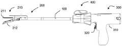
图1是外科器械一个实施例的结构示意图。图示实施例是内窥镜式器械,一般来说,本文所述的外科器械的实施例是内窥镜式外科切割吻合器械。然而,应该指出的是,外科器械还可以是非内窥镜式外科切割吻合器械,例如用于开放手术的开放式外科器械。FIG. 1 is a schematic structural diagram of an embodiment of a surgical instrument. The illustrated embodiment is an endoscopic instrument, and generally, the embodiments of the surgical instruments described herein are endoscopic surgical cutting and stapling instruments. It should be noted, however, that the surgical instrument may also be a non-endoscopic surgical cutting and stapling instrument, such as an open surgical instrument for open surgery.
图1、图2示出的外科器械,包括彼此可拆卸分离的手柄组件和装载单元200,其中,手柄组件可适配不同类型的装载单元200,装载单元200的远端设有末端执行器210,其包括钉砧组件211和钉仓组件212,钉砧组件211和钉仓组件212形成钳口,所述末端执行器210适于执行具体的手术操作,例如对组织进行夹持、缝合/吻合、切割等。在末端执行器210内设置有用于执行具体手术操作的可移动击发构件(图1中未示出)。手柄组件包括手柄部300和细长体组件100,细长体组件100限定了纵向轴线,该纵向轴线从手柄部300的远端向远侧延伸。细长体组件100的远端与装载单元200可拆卸连接。The surgical instrument shown in FIGS. 1 and 2 includes a handle assembly and a
进一步如图1和2所示,该手柄部300包括手柄主体310和致动部件320,通过操作致动部件320,实现末端执行器210的闭合、打开、缝合/吻合、切割等操作。Further as shown in FIGS. 1 and 2 , the
在可替代的实施例中,手柄部300和细长体组件100能够彼此可拆卸分离,手柄部300被配置为选择性地连接细长体组件100。In an alternative embodiment, the
应该指出的是,虽然本文描述的外科器械的实施例配置的是切割吻合组织的末端执行器210,但是在可替代的实施例中,还可配置用于切割吻合组织的其他技术。例如,也可使用利用射频(RF)能量或粘合剂来吻合组织的末端执行器。It should be noted that while the embodiments of the surgical instrument described herein are configured with an
进一步如图1所示,本发明实施例所述的手柄组件还包括旋转头组件400,所述旋转头组件400安装在手柄部300的远侧,并且与细长体组件100的近端固定连接,当旋转头组件400被操作绕外科器械的纵向轴线旋转时,能够带动细长体组件100和装载单元200一同旋转。As further shown in FIG. 1 , the handle assembly according to the embodiment of the present invention further includes a
上述实施例所述的外科器械,还包括装载单元类型识别机构,用来识别装载单元的类型,从而控制驱动系统根据装载单元的类型来提供驱动。The surgical instrument described in the above embodiments further includes a loading unit type identification mechanism for identifying the type of the loading unit, so as to control the drive system to provide driving according to the type of the loading unit.
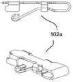
具体地,如图4所示,装载单元识别机构包括装载单元类型识别部100a,该装载单元类型识别部100a设置在细长体组件100的远侧,基于识别机构的判断可以确定装载单元200的类型,以便于进一步的手术操作。以下介绍装载单元类型识别部100a的具体实现方式。Specifically, as shown in FIG. 4 , the loading unit identification mechanism includes a loading unit
<装载单元类型识别部100a><Loading Unit
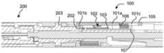
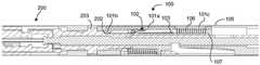
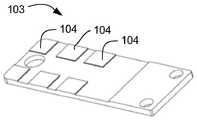
如图6所示,装载单元类型识别部100a包括:滑动连接于所述细长体组件100的外壳105内的第一滑动件101、设置于所述第一滑动件101上并随之滑动的第一触发件102、固定连接于所述细长体组件100的支撑架107内的第一电路板103,以及配置为根据所述第一电路板103的反馈信号确定所述装载单元200的类型的控制器。如图7-9所示,所述第一滑动件101用于与装载单元200配合,不同类型的装载单元200插接时触发所述第一滑动件101滑动至不同的目标位置,进而带动所述第一触发件102滑动至不同的目标位置;所述第一电路板103沿所述第一滑动件101的滑动方向间隔设置至少两个第一响应件104,每个所述第一响应件104用于与所述第一触发件102配合,提供与装载单元类型相对应的电信号。例如,通过所述第一响应件104与所述第一触发件102配合,打开或切断一个第一电支路A1,其中,每个所述第一电支路A1上的负载值不同。As shown in FIG. 6 , the loading unit
图3、以及图7-图9给出上述装载单元类型识别部100a用于识别三种不同类型的装载单元200的具体实施方式,其中,装载单元200的近侧设置特征部201,特征部201具有识别作用面202,不同类型的装载单元200的识别作用面202分别设置在沿纵向不同的目标位置,这样,装载单元200插接于细长体组件100上时,其特征部201的识别作用面202驱动所述第一滑动件101滑动与该装载单元200类型对应的距离。例如,如图3所示,I型装载单元200的识别作用面202设置在离其近侧端部最近的位置,如图8所示,当该I型装载单元200插入细长体组件100时,识别作用面202抵推第一滑动件101,进而带动第一触发件102滑动至第一目标位置,所述第一触发件102与所述细长体组件100远侧的第一响应件104配合,使得该第一响应件104连接的第一电支路A1状态发生变化,所述第一电路板103获得第一电信号发送至控制器,控制器根据第一电信号确定装载单元200为Ⅰ型装载单元200。类似的,III型装载单元200的识别作用面202设置在离其近侧端部最远的位置,如图7所示,当III型装载单元200被插入细长体组件100时,其识别作用面202抵推第一滑动件101,进而带动第一触发件102滑动至第二目标位置,所述第一触发件102与接近所述细长体组件100近端的第一响应件104配合,使得该第一响应件104连接的第一电支路A1状态发生变化,所述第一电路板103获得第二电信号发送至控制器,控制器根据第二电信号确定装载单元200为III型装载单元200;以此类推,如图9所示,控制器可以确定II型装载单元200,该II型装载单元的识别特征部201的识别作用面202设置在最近侧和最远侧之间。3, and FIGS. 7-9 show specific implementations of the above-mentioned loading unit
由于所述第一响应件104间隔设置于所述第一电路板103上,第一触发件102在滑动的过程中,位于两个第一响应件104之间的部分无电信号输出,通过调整不同第一电支路A1之间的负载差值,可以实现电学特征的宽识别容限,提高识别系统的可靠性。Since the
具体地,所述第一电支路A1上的负载的选择不唯一,例如可以采用电阻、二极管,电感,有源负载等;所述第一电路板103输出的电信号同样采用不同种类,例如采用电压模拟信号,还可以是调频,调幅,电容,电感等电信号。Specifically, the selection of the load on the first electrical branch A1 is not unique, for example, resistors, diodes, inductors, active loads, etc. can be used; the electrical signals output by the
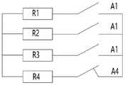
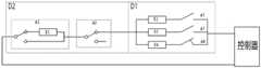
如图10a-10c示出一种以电阻作为负载的装载单元类型识别电路D1;具体地,一种实施方式中,如图10a所示,所述装载单元类型识别电路D1由两路所述第一电支路A1并联而成,其用于实现两种类型的装载单元200的识别;一种方式中,如图10b所示,所述装载单元类型识别电路D1由两路所述第一电支路A1与第一负载支路A4并联而成,其用于实现两种类型的装载单元200的识别;所述第一负载支路A4上连接所述第一负载R4,以使该所述装载单元类型识别电路D1形成常通形式的电路;如图10c所示,所述装载单元类型识别电路D1由三路所述第一电支路A1与第一负载支路A4并联而成,其用于实现三种类型的装载单元200的识别。Figures 10a-10c show a loading unit type identification circuit D1 using a resistor as a load; specifically, in an embodiment, as shown in Figure 10a, the loading unit type identification circuit D1 consists of two circuits of the first An electrical branch circuit A1 is formed in parallel, which is used to realize the identification of two types of
此外,如图10b所示,所述第一负载支路A4上连接所述第一负载R4,以使该所述装载单元类型识别电路D1形成常通形式的电路,用于对未插入装载单元200状态的自检。例如,当装载单元200未被插入时,第一负载支路A4处于连通状态,使整个电路形成闭合状态。进一步地,插入装载单元200后,例如III型装载单元200后,其识别作用面202接触第一滑动件101,第一触发件102与远端的第一响应件104持续配合,控制器识别该装载单元200的类型;插入其他类型的装载单元200,例如,I型装载单元或II型装载单元,其特征部201的识别作用面202均能抵推第一滑动件101,导通相应的第一电支路A1并提供相应的识别电信号,由控制器完成对相应装载单元类型的识别操作。In addition, as shown in FIG. 10b, the first load R4 is connected to the first load branch A4, so that the loading unit type identification circuit D1 forms a normally-on circuit, which is used for unplugged loading units. 200 state self-test. For example, when the
一种具体实施方式中,所述第一触发件102与所述第一响应件104配合时接通所述第一电支路A1,所述第一触发件102与所述第一响应件104为面接触或线接触。通过将第一触发件102与所述第一响应件104的配合区域设置为面接触或线接触,可通过调整第一触发件102与第一响应件104的宽度可以实现宽滑动范围,提高识别系统的可靠性,具体地,所述第一响应件104可以设置不同面积的识别信息区间,所述第一响应件104区域较大时其可以与所述第一触发件102接通面积较大,或者,第一触发件102设置为较大的接触面积,以便于与第一响应件104接通,该两种方式均可以使该装载单元类型识别部100a的识别容限较宽,提高其识别准确度。In a specific embodiment, when the
如图11和图12所示,所述第一响应件104为设置于所述第一电路板103上的导电触片104a,所述第一触发件102为弹性导电插片102a,所述第一触发件102一端连接于所述第一滑动件101上,另一端抵接于所述第一电路板103上,所述第一滑动件101带动所述弹性导电插片102a滑动至与所述导电触片104a接触时,将所述导电触片104a所在的第一电支路A1连通。更具体地,如图12和图15所示,所述导电触片104a可成型为方形片状,其可以略凸出或凹陷于电路板。如图14所示,所述弹性导电插片102a则成型为大致V字形插片结构,所述第一触发件102一端可插接于所述第一滑动件101上,具体地,所述第一滑动件101的其中一板面上设有插接槽口,V字形插片的一侧插接于所述第一滑动件101的插接槽口上;V字形插片的另一侧具有向外侧突出的弧形凸起,该弧形凸起部分则用于与所述导电触片104a配合实现线接触。这样,通过调整弧形凸起的宽度可以调整与所述导电触片104a的接触面积。更具体地,一种实施方式中,还可以在所述弧形凸起的表面上连接片状导电凸片,以使该弹性导电插片102a与所述导电触片104a形成面接触,通过调整片状导电凸片的大小调整与导电触片104a的接触面积。As shown in FIG. 11 and FIG. 12 , the
为了提高所述第一响应件104与所述第一触发件102的接触面积,所述第一滑动件101上可拆卸连接两个所述第一触发件102,所述第一触发件102沿垂直于所述第一滑动件101的滑动方向上间隔设置,所述第一电路板103上沿垂直所述第一滑动件101的滑动方向上设置两个所述第一响应件104,所述第一响应件104与所述第一触发件102的位置一一对应,以在两个第一触发件102与对应的两个第一响应件104配合时导通识别电路。In order to increase the contact area between the
另一种具体实施方式中,所述第一触发件102与所述第一响应件104配合时使所述第一电支路A1断开,所述第一触发件102的长度与相邻所述第一响应件104之间的间距匹配,以使其移动至不同位置处时只切断其中一个所述第一响应件104所在的第一电支路A1,由其他导通的第一电支路A1生成对应的识别电信号。In another specific embodiment, when the
或者,在可替代的实施例中,所述第一触发件102的长度与相邻所述第一响应件104之间的间距匹配,以使其移动至不同位置时可同时切断多个第一电支路A1;例如,当第一触发件102移动至第一目标位置时与第一组及第二组第一响应件104配合,同时切断两个第一电支路A1、移动至第二目标位置时与第二组与第三组第一响应件104配合,同时切断两个第一电支路A1,由其他支路组合形成识别电信号,依此类推。Or, in an alternative embodiment, the length of the
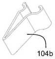
如图16-图18所示,所述第一响应件104包括互相抵接的两个弹性导电触片104b,两个所述弹性导电触片104b电连接并形成一个所述第一电支路A1;如图17所示,所述第一触发件102为设置于所述第一滑动件101上的绝缘凸起102b,所述第一滑动件101带动所述绝缘凸起102b滑动至两个所述弹性导电触片104b之间时,将所述两个弹性导电触片104b所在的第一电支路A1切断。As shown in FIGS. 16-18 , the
具体地,如图16所示,所述第一电路板103上沿所述细长体组件100的轴向成型两条平行设置的限位板1031,所述第一响应件104安装于两个限位板1031之间。其中,所述弹性导电触片104b的结构不唯一,一种具体方式中,所述弹性导电触片104b为V形,两个V形弹性导电触片104b的一个侧板面抵接于所述限位板1031上,另一侧板面则互相抵接形成电连接,为了使两个弹性导电触片104b之间可靠地电连接,所述V形弹性导电触片104b的一侧板面上向外形成弧形凸出部(参见图18),其使两个V形弹性导电触片104b形成较为可靠的线接触或面接触。为了使第一触发件102较为顺利地切断两个所述第一响应件104的连接,所述第一触发件102成型为近端部具有尖角结构的凸起(参见图17),使其近端部的宽度较窄,使其能够容易地插于两个V字形弹性导电触片104b之间,第一触发件102主体段与尖角段平滑过渡,当所述第一触发件102滑动至目标位置时,所述第一触发件102的主体段与所述第一响应件104配合,且第一触发件102的至少一部分为不导电材料制成),以实现可靠地切断。Specifically, as shown in FIG. 16 , two parallel limiting
具体地,如图4和图6所示,所述细长体组件100包括细长筒形的外壳105,所述第一滑动件101成型为长条形片状结构,其沿细长筒形外壳105的轴向滑动;为了使第一滑动件101在装配单元未插接状态下滑动至该细长体组件100的近端,所述细长体组件100的外壳105与所述第一滑动件101之间设有第一复位件106,所述第一复位件106向所述第一滑动件101施加朝向远端的作用力,这样,在所述第一复位件106的作用下,所述第一滑动件101滑动至接近所述细长体组件100的远端的初始状态。Specifically, as shown in FIGS. 4 and 6 , the
优选地,如图13所示,为了增加第一滑动件101与装载单元200的识别作用面202的抵推作用,在第一滑动件101的近端设有向轴心方向的凸起101b,第一滑动件101上纵轴上设有复位孔101c,外壳105与复位孔101c之间设有第一复位件106。Preferably, as shown in FIG. 13 , in order to increase the pushing action between the first sliding
具体地,如图6所示,所述细长体组件100的外壳105内设有支撑架107,所述支撑架107上设有滑槽,所述第一电路板103固定连接于所述滑槽底部,所述第一滑动件101滑动连接于所述滑槽的侧壁上,所述第一复位件106位于所述滑槽的近端与所述第一滑动件101的近端之间。Specifically, as shown in FIG. 6 , the
上述实施例所述的外科器械中,如图22所示,所述装载单元200的近端形成用于表征装载单元200类型的特征部201,以及用于与细长体组件100连接的连接结构;其包括沿远端至近端依次连接的第一插接段205和第二插接段206,所述第一插接段205的外径大于所述第二插接段206的外径,所述第一插接段205上设置旋转锁定部203,用于与细长体组件100实现旋转锁定;所述第二插接段206则形成用于表征不同类型装载单元200的特征部201。其中,不同所述装载单元200的所述第二插接段206的长度不同,所述第一插接段205与所述第二插接段206之间的台阶面抵接于所述第一滑动件101上,台阶面为识别作用面202。In the surgical instrument described in the above embodiment, as shown in FIG. 22 , the proximal end of the
此外,上述实施例所述的外科器械还包括装载单元安装到位识别机构,用来识别装载单元是否安装到位,当监测到装载单元已安装到位后,再控制驱动装载单元,避免出现因装载单元未安装到位,即进行手术操作而产生的医疗事故。In addition, the surgical instrument described in the above-mentioned embodiment further includes a loading unit installation position identification mechanism, which is used to identify whether the loading unit is installed in position. When it is detected that the loading unit is installed in position, the loading unit is controlled to drive the loading unit, so as to avoid the failure of the loading unit due to the failure of the loading unit. Installed in place, that is, medical malpractice caused by surgical operations.
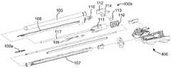
具体地,如图4所示,装载单元安装到位识别机构还包括安装到位识别部100b,设在细长体组件100内,基于安装到位识别部100b的判断可以确定装载单元200是否安装到位,以便于进一步的手术操作。在可替代的实施例中,安装到位识别部100b还可设置在旋转头组件400,或手柄部300内。以下介绍装载单元安装到位识别部100b的具体实现方式。Specifically, as shown in FIG. 4 , the loading unit installation position identification mechanism further includes an installation
<装载单元安装到位识别部100b><Loading Unit Installation
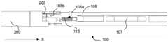
如图4所示为装载单元安装到位识别部100b的具体实施方式,其包括:分别滑动连接于所述细长体组件100的外壳105内的第二滑动件108与第三滑动件109,所述第二滑动件108用于与装载单元200的旋转锁定部203配合,所述第三滑动件109用于与所述装载单元200的近端端面204配合,在所述装载单元200处于插接到位与旋转到位时,所述第二滑动件108滑动至不同设定位置,所述第三滑动件109滑动至相同设定位置;第二触发件110与第三触发件111,所述第二触发件110与所述第二滑动件108连接,第三触发件111与所述第三滑动件109连接;固定连接于所述细长体组件100的外壳105内的第二电路板112,所述第二电路板112上设置第二响应件113和第三响应件114,所述第二响应件113用于与所述第二触发件110配合以使第二电支路A2在第一状态与第二状态之间转换,第三响应件114用于与所述第三触发件111配合以使第三电支路A3在第三状态与第四状态之间转换;对应所述装载单元200的插接到位位置与旋转到位位置,所述第二电路板112输出两种不同状态;所述控制器配置为根据所述第二电路板112的反馈信号确定所述装载单元200是否安装到位。As shown in FIG. 4 , the specific embodiment of the
具体地,所述第二电支路A2的第一状态与第二状态是指输出信号不同的两种电路状态,例如第一状态可以为电支路接通状态,第二状态可以为电支路断开状态;或者,第一状态可以为负载为L1的电支路,其输出信号为V1;所述第二状态为负载为L2的电支路,其输出信号为V2;同样地,所述第三电支路A3的第三状态与第四状态同样指输出信号不同的两种电路状态,在此不再赘述。Specifically, the first state and the second state of the second electrical branch A2 refer to two circuit states with different output signals, for example, the first state may be the electrical branch on state, and the second state may be the electrical branch Alternatively, the first state may be an electrical branch with a load of L1, and its output signal is V1; the second state may be an electrical branch with a load of L2, and its output signal is V2; The third state and the fourth state of the third electrical branch A3 also refer to two circuit states with different output signals, which will not be repeated here.
装载单元200经过插接到位后旋转的方式实现其锁定于细长体组件100上,具体地,如图22所示,所述装载单元200的旋转锁定部203为设置于所述装载单元200端部的锁定凸起,所述细长体组件100外壳105内部设置锁定滑槽118,所述锁定凸起与所述锁定滑槽118配合实现所述装载单元200旋转锁定。The
更具体地,如图19和图23a所示,第二滑动件108可滑动地设置在细长体组件100内的支撑架107上,第二滑动件108的远端设有锁止部108b和复位孔108a,复位孔108a和细长体组件100外壳105之间设有复位件115,复位件115可为弹簧、弹片或簧片等偏压件;如图23b所示,装载单元200沿X方向插入细长体组件100中,装载单元200的旋转锁定部203抵推第二滑动件108向近侧移动,以使旋转锁定部203处于锁定滑槽118的拐角处;图23c所示,装载单元200沿Y方向旋转,旋转锁定部203移动以给第二滑动件108让位,在复位件115偏压力的作用下第二滑动件108复位,在第二滑动件108和锁定滑槽118的锁定部的限位下,使旋转锁定部203锁定在细长体组件100内。More specifically, as shown in Figures 19 and 23a, the second sliding
由于装载单元200通过旋转锁定的方式安装于细长体组件100上,装载单元200经过插接到位后旋转的方式实现其锁定于细长体组件100上,因此,装载单元200具有插接到位位置与旋转到位位置。在插接到位位置时,所述装载单元200的旋转锁定部203抵推所述第二滑动件108移动至与所述第二响应件113配合的位置处,使第二电支路A2的状态改变,例如从切断状态改变为接通状态,所述装载单元200的近端端面204推动所述第三滑动件109移动至与所述第三响应件114配合的位置处,所述第三电支路A3的状态改变,例如从接通状态改变为切断状态;此时所述第二电路板112输出第一信号,例如,所述第二电支路A2状态为1,第三电支路A3状态为0;在旋转到位位置时,由于所述装载单元200的旋转锁定部203旋转,其与所述第二滑动件108脱离,此时所述第二滑动件108移动至不与第二响应件113配合的位置处,使所述第二电支路A2状态改变,例如,从接通状态改变为切断状态,而所述装载单元200的近端端面204在旋转的过程中其轴向位置不变,因此,其保持与所述第二响应件113配合,所述第三电支路A3的状态保持不变;此时,所述第二电路板112则输出第二信号,例如,所述第二电支路A2状态为0,第三电支路A3状态为0;所述控制器根据所述第二电路板112输出的电信号则可以判断该装载单元200是否安装到位。Since the
此外,第二复位件115的设置,使装载单元200处于旋转到位位置时,第二触发件110与所述第二响应件113能够可靠地分离,所述第二复位件115向所述第二滑动件108施加朝向远端的作用力。所述装载单元200处于插接到位位置时,装载单元200的旋转锁定部203抵接于第二滑动件108上,所述第二触发件110触发所述第二响应件113使所述第二电支路A2处于第一状态;所述装载单元200处于旋转到位位置时,在所述第二复位件115的作用下所述第二滑动件108移动至细长体组件100的远端,所述第二触发件110与所述第二响应件113分离使所述第二电支路A2处于第二状态。In addition, the setting of the
具体地,为了使装载单元200未插接位置与插接到位及旋转到位位置进行区分,即在装载单元200拆卸后,装载单元安装到位识别部能够有效复位,优选地,所述第三滑动件109与所述细长体组件100的外壳105之间设置第三复位件116,所述第三复位件116向所述第三滑动件109施加朝向远端的作用力。所述装载单元200处于插接到位位置及旋转到位位置时,所述第三触发件111触发所述第三响应件114使所述第三电支路A3处于第一状态;所述装载单元200处于未插接位置时,所述第三复位件116的作用下所述第三滑动件109移动至细长体组件100的远端,所述第三触发件111与所述第三响应件114分离使所述第三电支路A3处于第二状态。这样,所述装载单元200处于未插接位置、插接到位位置以及旋转到位位置时,所述第二电路板112能够输出不同的信号,以使控制器判断其是否安装到位。Specifically, in order to distinguish the unplugged position of the
所述第二触发件110与第二响应件113以及所述第三触发件111与第三响应件114之间的配合方式不唯一,以下通过两种不同的实施方式进行说明。The mode of cooperation between the
一种具体实施方式中,所述第二响应件113及第三响应件114为电开关,所述第二触发件110与所述第三触发件111通过触发该电开关改变其开关状态以改变第二电支路A2与第三电支路A3的状态。更具体地,所述第二响应件113为第一电开关,所述第二触发件110滑动至抵压所述第二响应件113的位置时,所述第一电开关的状态切换(例如从接通状态切换为断开状态),使所述第二电支路A2处于第一状态,所述第二触发件110滑动至与所述第二响应件113分离的位置时,所述第一电开关的状态切换(例如从断开状态切换为接通状态),使所述第二电支路A2处于第二状态;所述第三触发件111滑动至抵压所述第三响应件114的位置时,所述第二电开关的状态切换(例如从接通状态切换为断开状态),使所述第三电支路A3处于第三状态,所述第三触发件111滑动至与所述第三响应件114分离的位置时,所述第二电开关的状态切换(例如从接通状态切换为断开状态),使所述第三电支路A3处于第四状态。更具体地,所述电开关为推弹式电开关,所述第二触发件110或第三触发件111滑动至所述推弹式电开关的位置处时,推动其状态改变,当离开所述推弹式电开关的位置时,电开关的状态再次变化。In a specific implementation manner, the
另一种具体实施方式中,所述第二响应件113/第三响应件114为电触点,所述第二触发件110与所述第二响应件113配合形成接通或切断所述第二电支路A2的开关;所述第三触发件111与所述第三响应件114配合形成接通或切断所述第二电支路A2的开关。更具体地,所述第二触发件110滑动至抵接所述第二响应件113的位置时,所述第二触发件110与所述电触点接通所述第二电支路A2;所述第二触发件110滑动至与所述第二响应件113分离的位置时切断所述第二电支路A2;所述第三触发件111滑动至抵接所述第三响应件114的位置时,所述第三触发件111与所述电触点接通所述第三电支路A3;所述第三触发件111滑动至与所述第三响应件114分离的位置时切断所述第三电支路A3。In another specific implementation manner, the
所述装载单元类型识别部100a及装载单元安装到位识别部100b的检测电路的结构不唯一;一种具体实施方式中,若干所述第一电支路A1并联连接形成装载单元类型识别电路D1;所述第二电支路A2与所述第三电支路A3并联连接形成装载单元安装到位识别电路D2;装载单元类型识别电路D1与装载单元安装到位识别电路D2互相独立设置,两者分别电连接至控制器上。The structure of the loading unit
为了使简化装载单元类型识别部100a及装载单元安装到位识别部100b的检测电路,另一种实施方式中,若干所述第一电支路A1并联连接形成装载单元类型识别电路D1,所述第二电支路A2与所述第三电支路A3串联连接形成装载单元安装到位识别电路D2;装载单元类型识别电路D1与装载单元安装到位识别电路D2串联连接并连接至控制器上形成电回路。更具体地,所述装载单元类型识别电路D1还包括与所述第一电支路A1并联连接的第一负载支路A4;所述装载单元安装到位识别电路D2中,所述第二电支路A2的第一状态与所述第二状态对应负载值不同的两个电支路,所述第三电支路A3的第三状态与第四状态对应接通电支路与断开电支路;所述装载单元200处于未插接位置与旋转到位位置时,所述装载单元类型识别电路D1与所述装载单元安装到位识别电路D2处于接通状态且两种状态下的负载值不同,所述控制器根据整个电路的负载值确定该装载单元200的状态;所述装载单元200处于插接到位位置时,所述装载单元类型识别电路D1与所述装载单元安装到位识别电路D2处于断开状态。In order to simplify the detection circuit of the loading unit
具体地,如图21a-图21c所示为装载单元类型识别电路D1与装载单元安装到位识别电路D2串联连接的一种具体实施方式,其中,所述第二电支路A2中的第一状态下负载值为R1,第二状态下负载值为0;所述第三电支路A3中第三状态为接通状态,第四状态为断开状态,所述装载单元类型识别电路D1中包括两个并联连接的第一电支路A1以及一个负载值为R4的第一负载支路A4。Specifically, as shown in FIGS. 21 a to 21 c , a specific implementation manner in which the loading unit type identification circuit D1 and the loading unit installation position identification circuit D2 are connected in series, wherein the first state in the second circuit branch A2 The lower load value is R1, and the load value in the second state is 0; the third state in the third electrical branch A3 is an on state, and the fourth state is an off state, and the loading unit type identification circuit D1 includes: Two first electrical branches A1 connected in parallel and a first load branch A4 with a load value R4.
如图21a所示,所述装载单元200处于未插接位置时,所述第二电支路A2处于第一状态,所述第三电支路A3处于第三状态,所述装载单元类型识别电路D1通过第一负载支路A4处于接通状态,因此,整个电回路处于接通状态,并且基于第二电支路A2的负载R1与第一负载支路A4的负载R4;输出电信号为A1。As shown in FIG. 21a, when the
如图21b所示,所述装载单元200处于插接到位位置时,所述第二电支路A2切换至第二状态,所述第三电支路A3切换为第四状态,使整个电回路处于断开状态,所述控制器不能接受电信号;As shown in FIG. 21b, when the
如图21c所示,所述装载单元200处于旋转到位位置时,所述第二电支路A2再次切换至第一状态,所述第三电支路A3切换为第三状态,所述装载单元类型识别电路D1中,其中一个所述第一电支路A1接通,例如是负载为R2的第一电支路A1接通,整个电回路处于接通状态,并且基于第二电支路A2的负载R1、第一电支路A1的负载R2以及第一负载支路A4的负载R4;输出电信号为A2。As shown in FIG. 21c, when the
通过上述电路实现了在装载单元200未插接状态下,所述装载单元类型识别电路D1与所述装载单元安装到位识别电路D2处于接通状态,使外科器械处于自检状态;当装载单元200安装到位后,所述装载单元类型识别电路D1与所述装载单元安装到位识别电路D2再次处于接通状态且与未插接状态下的输出信号不同,控制器确定装载单元200安装到位且能够根据信号识别装载单元200的类型。The above circuit realizes that when the
具体地,所述第二滑动件108与第二触发件110之间的连接方式不唯一;一种具体方式中,两者采用插接连接固定;其中,所述第二滑动件108成型为细长杆形,其近端部设置插接孔,所述第二触发件110上设置插接于该插接孔的插接杆;更具体地,所述细长体组件100的外壳105上具有开口,所述第二触发件110穿设于所述开口处,如图20所示,所述第二触发件110包括:触发主体1101、滑块1102,插接杆1103以及触发杆1104;其中,触发主体1101与所述细长体组件100的外壳105固定连接,所述触发主体1101上设置滑道,所述滑块1102沿所述滑道滑动连接于所述触发主体1101并位于所述细长体组件100的外壳105的外侧;所述插接杆1103连接于所述滑块1102的远端并用于与所述第二滑动件108插接连接;所述触发杆1104连接于所述滑块1102的近端并用于触发所述第二响应件113。更具体地,所述触发杆1104上设置凸起部用于在滑动过程中抵压所述第二响应件113。Specifically, the connection mode between the second sliding
具体地,所述第三滑动件109与第三触发件111之间的连接方式不唯一;一种方式中,所述第三滑动件109成型为细长管形,其直接与位于所述细长体组件100近端的第三触发件111连接;另一种方式中,如图4所示,所述第三滑动件109成型与所述第三触发件111通过中间连接件117连接。更具体地,所述第三滑动件109成型为细长片状,并位于所述细长体组件100的远端,所述中间连接件117成型为套管形式,其穿设于中空的所述支撑架107内,所述第三触发件111成型为块体形,位于所述细长体组件100的近端。所述第三触发件111上设置凸起部用于在滑动过程中抵压所述第三响应件114。Specifically, the connection mode between the third sliding
具体地,该外科器械还包括指示单元,所述指示单元用于指示所述装载单元200的类型,所述控制器根据所述第一电路板103发出的电信号确定装载单元200的类型后,控制所述指示单元进行指示,以提示该外科器械的使用者当前装载单元200的类型。所述指示单元还用于指示所述装载单元200是否安装到位,所述控制器根据所述第二电路板112的反馈信号,使指示单元发出装载单元200安装到位的第二指示信号。Specifically, the surgical instrument further includes an indicating unit, which is used to indicate the type of the
所述指示单元的具体指示方式及实现结构不唯一,可以采用声音指示、机械指示、指示灯指示或文字指示的方式;相应地,指示单元可采用蜂鸣器、突出/凹陷部指示、发光二极管或显示屏等硬件结构以实现。另外,所述指示单元可以安装于该外科器械的手柄部300上,以方便使用者接受到指示信号。The specific indication method and implementation structure of the indication unit are not unique, and can be in the form of sound indication, mechanical indication, indicator light indication or text indication; Or a hardware structure such as a display screen to achieve. In addition, the indicating unit can be installed on the
显然,上述实施例仅仅是为清楚地说明所作的举例,而并非对实施方式的限定。对于所属领域的普通技术人员来说,在上述说明的基础上还可以做出其它不同形式的变化或变动。这里无需也无法对所有的实施方式予以穷举。而由此所引伸出的显而易见的变化或变动仍处于本发明的保护范围之中。Obviously, the above-mentioned embodiments are only examples for clear description, and are not intended to limit the implementation manner. For those of ordinary skill in the art, changes or modifications in other different forms can also be made on the basis of the above description. There is no need and cannot be exhaustive of all implementations here. However, the obvious changes or changes derived therefrom still fall within the protection scope of the present invention.
Claims (19)
Priority Applications (6)
| Application Number | Priority Date | Filing Date | Title |
|---|---|---|---|
| CN202110865511.XACN113397616B (en) | 2021-07-29 | 2021-07-29 | a surgical instrument |
| CN202210905155.4ACN115670539A (en) | 2021-07-29 | 2021-07-29 | a surgical instrument |
| PCT/CN2022/106013WO2023005693A1 (en) | 2021-07-29 | 2022-07-15 | Surgical instrument |
| JP2024505542AJP2024528126A (en) | 2021-07-29 | 2022-07-15 | Surgical Instruments |
| EP22848298.0AEP4378397A4 (en) | 2021-07-29 | 2022-07-15 | SURGICAL INSTRUMENT |
| US18/424,494US20240164781A1 (en) | 2021-07-29 | 2024-01-26 | Surgical instrument |
Applications Claiming Priority (1)
| Application Number | Priority Date | Filing Date | Title |
|---|---|---|---|
| CN202110865511.XACN113397616B (en) | 2021-07-29 | 2021-07-29 | a surgical instrument |
Related Child Applications (1)
| Application Number | Title | Priority Date | Filing Date |
|---|---|---|---|
| CN202210905155.4ADivisionCN115670539A (en) | 2021-07-29 | 2021-07-29 | a surgical instrument |
Publications (2)
| Publication Number | Publication Date |
|---|---|
| CN113397616A CN113397616A (en) | 2021-09-17 |
| CN113397616Btrue CN113397616B (en) | 2022-09-06 |
Family
ID=77687879
Family Applications (2)
| Application Number | Title | Priority Date | Filing Date |
|---|---|---|---|
| CN202210905155.4APendingCN115670539A (en) | 2021-07-29 | 2021-07-29 | a surgical instrument |
| CN202110865511.XAActiveCN113397616B (en) | 2021-07-29 | 2021-07-29 | a surgical instrument |
Family Applications Before (1)
| Application Number | Title | Priority Date | Filing Date |
|---|---|---|---|
| CN202210905155.4APendingCN115670539A (en) | 2021-07-29 | 2021-07-29 | a surgical instrument |
Country Status (5)
| Country | Link |
|---|---|
| US (1) | US20240164781A1 (en) |
| EP (1) | EP4378397A4 (en) |
| JP (1) | JP2024528126A (en) |
| CN (2) | CN115670539A (en) |
| WO (1) | WO2023005693A1 (en) |
Families Citing this family (2)
| Publication number | Priority date | Publication date | Assignee | Title |
|---|---|---|---|---|
| CN115670539A (en)* | 2021-07-29 | 2023-02-03 | 天津瑞奇外科器械股份有限公司 | a surgical instrument |
| CN116849742A (en)* | 2023-07-31 | 2023-10-10 | 无锡贝恩外科器械有限公司 | An electric stapler capable of recognizing at least four staple cartridge components |
Citations (6)
| Publication number | Priority date | Publication date | Assignee | Title |
|---|---|---|---|---|
| CN103349558A (en)* | 2007-10-05 | 2013-10-16 | 柯惠Lp公司 | Powered surgical stapling device |
| CN103767749A (en)* | 2012-10-18 | 2014-05-07 | 柯惠Lp公司 | Surgical device identification |
| CN105078530A (en)* | 2014-05-05 | 2015-11-25 | 柯惠Lp公司 | End-effector force measurement drive circuit |
| CN105213041A (en)* | 2014-06-09 | 2016-01-06 | 柯惠Lp公司 | Certification and information system for reusable surgical instruments |
| CN108969123A (en)* | 2017-05-30 | 2018-12-11 | 柯惠Lp公司 | Certification and information system for reusable surgical instrument |
| CN111759385A (en)* | 2020-07-17 | 2020-10-13 | 天津瑞奇外科器械股份有限公司 | Electric anastomat and loading unit thereof |
Family Cites Families (18)
| Publication number | Priority date | Publication date | Assignee | Title |
|---|---|---|---|---|
| JPS5940603U (en)* | 1982-09-08 | 1984-03-15 | 三菱重工業株式会社 | hydraulic cylinder |
| JP2000046502A (en)* | 1998-07-24 | 2000-02-18 | Honda Motor Co Ltd | Relative displacement detector |
| US7464849B2 (en)* | 2006-01-31 | 2008-12-16 | Ethicon Endo-Surgery, Inc. | Electro-mechanical surgical instrument with closure system and anvil alignment components |
| JP2008064208A (en)* | 2006-09-07 | 2008-03-21 | Tokutake Seisakusho:Kk | Cylinder device with stroke detection function |
| US8733614B2 (en)* | 2006-10-06 | 2014-05-27 | Covidien Lp | End effector identification by mechanical features |
| US7753246B2 (en)* | 2007-01-31 | 2010-07-13 | Tyco Healthcare Group Lp | Surgical instrument with replaceable loading unit |
| US7793812B2 (en)* | 2008-02-14 | 2010-09-14 | Ethicon Endo-Surgery, Inc. | Disposable motor-driven loading unit for use with a surgical cutting and stapling apparatus |
| US7913891B2 (en)* | 2008-02-14 | 2011-03-29 | Ethicon Endo-Surgery, Inc. | Disposable loading unit with user feedback features and surgical instrument for use therewith |
| US8453907B2 (en)* | 2009-02-06 | 2013-06-04 | Ethicon Endo-Surgery, Inc. | Motor driven surgical fastener device with cutting member reversing mechanism |
| US9421014B2 (en)* | 2012-10-18 | 2016-08-23 | Covidien Lp | Loading unit velocity and position feedback |
| WO2014098246A1 (en)* | 2012-12-20 | 2014-06-26 | Olympus Corporation | Position detection sensor and manipulator |
| US9826976B2 (en)* | 2013-04-16 | 2017-11-28 | Ethicon Llc | Motor driven surgical instruments with lockable dual drive shafts |
| US10561418B2 (en)* | 2014-06-26 | 2020-02-18 | Covidien Lp | Adapter assemblies for interconnecting surgical loading units and handle assemblies |
| US10729435B2 (en)* | 2015-11-06 | 2020-08-04 | Covidien Lp | Adapter assemblies for interconnecting surgical loading units and handle assemblies |
| US10338259B2 (en)* | 2015-12-14 | 2019-07-02 | Covidien Lp | Surgical adapter assemblies and wireless detection of surgical loading units |
| US10314579B2 (en)* | 2016-01-07 | 2019-06-11 | Covidien Lp | Adapter assemblies for interconnecting surgical loading units and handle assemblies |
| WO2020131692A1 (en)* | 2018-12-21 | 2020-06-25 | Intuitive Surgical Operations, Inc. | Surgical instruments having mechanisms for identifying and/or deactivating stapler cartridges |
| CN115670539A (en)* | 2021-07-29 | 2023-02-03 | 天津瑞奇外科器械股份有限公司 | a surgical instrument |
- 2021
- 2021-07-29CNCN202210905155.4Apatent/CN115670539A/enactivePending
- 2021-07-29CNCN202110865511.XApatent/CN113397616B/enactiveActive
- 2022
- 2022-07-15JPJP2024505542Apatent/JP2024528126A/enactivePending
- 2022-07-15EPEP22848298.0Apatent/EP4378397A4/enactivePending
- 2022-07-15WOPCT/CN2022/106013patent/WO2023005693A1/ennot_activeCeased
- 2024
- 2024-01-26USUS18/424,494patent/US20240164781A1/enactivePending
Patent Citations (7)
| Publication number | Priority date | Publication date | Assignee | Title |
|---|---|---|---|---|
| CN103349558A (en)* | 2007-10-05 | 2013-10-16 | 柯惠Lp公司 | Powered surgical stapling device |
| CN103767749A (en)* | 2012-10-18 | 2014-05-07 | 柯惠Lp公司 | Surgical device identification |
| CN105078530A (en)* | 2014-05-05 | 2015-11-25 | 柯惠Lp公司 | End-effector force measurement drive circuit |
| CN105213041A (en)* | 2014-06-09 | 2016-01-06 | 柯惠Lp公司 | Certification and information system for reusable surgical instruments |
| CN111938733A (en)* | 2014-06-09 | 2020-11-17 | 柯惠Lp公司 | Authentication and information system for reusable surgical instruments |
| CN108969123A (en)* | 2017-05-30 | 2018-12-11 | 柯惠Lp公司 | Certification and information system for reusable surgical instrument |
| CN111759385A (en)* | 2020-07-17 | 2020-10-13 | 天津瑞奇外科器械股份有限公司 | Electric anastomat and loading unit thereof |
Also Published As
| Publication number | Publication date |
|---|---|
| WO2023005693A1 (en) | 2023-02-02 |
| CN115670539A (en) | 2023-02-03 |
| US20240164781A1 (en) | 2024-05-23 |
| EP4378397A4 (en) | 2024-11-13 |
| JP2024528126A (en) | 2024-07-26 |
| CN113397616A (en) | 2021-09-17 |
| EP4378397A1 (en) | 2024-06-05 |
Similar Documents
| Publication | Publication Date | Title |
|---|---|---|
| US20210290235A1 (en) | Adapter assemblies for interconnecting surgical loading units and handle assemblies | |
| US10874390B2 (en) | Loading unit detection assembly and surgical device for use therewith | |
| CN113397616B (en) | a surgical instrument | |
| US9949737B2 (en) | Adapter assemblies for interconnecting surgical loading units and handle assemblies | |
| US11547394B2 (en) | Adapter assemblies for interconnecting surgical loading units and handle assemblies | |
| US20220412823A1 (en) | End-effector force measurement drive circuit | |
| CN106943169B (en) | Adapter assembly for interconnecting a surgical loading unit with a handle assembly | |
| US11428591B2 (en) | End-effector force measurement drive circuit | |
| US9775607B2 (en) | Indicators for surgical staplers | |
| US7431720B2 (en) | Multi-function clamping device with stapler and ablation heads | |
| US20210353295A1 (en) | Single use electronics for surgical devices | |
| CN113543730B (en) | Potential conversion circuit for electric surgical stapler | |
| CN113796907B (en) | Stroke detection structure and control method thereof, electric stapler and medical equipment | |
| CN114948032B (en) | An electric stapler device for surgery | |
| US20240374258A1 (en) | Power control circuit for powered surgical stapler | |
| US10285690B2 (en) | Surgical instruments and switch assemblies thereof |
Legal Events
| Date | Code | Title | Description |
|---|---|---|---|
| PB01 | Publication | ||
| PB01 | Publication | ||
| SE01 | Entry into force of request for substantive examination | ||
| SE01 | Entry into force of request for substantive examination | ||
| GR01 | Patent grant | ||
| GR01 | Patent grant |