CN1133953A - reducer - Google Patents
reducerDownload PDFInfo
- Publication number
- CN1133953A CN1133953ACN95120130ACN95120130ACN1133953ACN 1133953 ACN1133953 ACN 1133953ACN 95120130 ACN95120130 ACN 95120130ACN 95120130 ACN95120130 ACN 95120130ACN 1133953 ACN1133953 ACN 1133953A
- Authority
- CN
- China
- Prior art keywords
- gear
- speed reducer
- output shaft
- reducer according
- pins
- Prior art date
- Legal status (The legal status is an assumption and is not a legal conclusion. Google has not performed a legal analysis and makes no representation as to the accuracy of the status listed.)
- Granted
Links
- 239000003638chemical reducing agentSubstances0.000titleclaimsabstractdescription67
- 238000003825pressingMethods0.000claimsabstractdescription50
- 230000005540biological transmissionEffects0.000claimsdescription64
- 230000033001locomotionEffects0.000claimsdescription18
- 230000008878couplingEffects0.000claimsdescription5
- 238000010168coupling processMethods0.000claimsdescription5
- 238000005859coupling reactionMethods0.000claimsdescription5
- 230000007246mechanismEffects0.000description21
- 239000013013elastic materialSubstances0.000description19
- 230000009471actionEffects0.000description11
- 230000009467reductionEffects0.000description11
- 229920001971elastomerPolymers0.000description10
- 238000005516engineering processMethods0.000description10
- 229920002635polyurethanePolymers0.000description10
- 239000004814polyurethaneSubstances0.000description10
- 239000000463materialSubstances0.000description9
- 230000002093peripheral effectEffects0.000description6
- 239000002184metalSubstances0.000description5
- 238000000034methodMethods0.000description5
- 230000003287optical effectEffects0.000description5
- 125000006850spacer groupChemical group0.000description5
- 229920003002synthetic resinPolymers0.000description5
- 239000000057synthetic resinSubstances0.000description5
- 239000000853adhesiveSubstances0.000description4
- 230000001070adhesive effectEffects0.000description4
- 230000008859changeEffects0.000description4
- 230000004048modificationEffects0.000description4
- 238000012986modificationMethods0.000description4
- 230000006835compressionEffects0.000description3
- 238000007906compressionMethods0.000description3
- 230000000694effectsEffects0.000description3
- 230000005489elastic deformationEffects0.000description3
- 238000004519manufacturing processMethods0.000description3
- 241000309551Arthraxon hispidusSpecies0.000description2
- 238000005452bendingMethods0.000description2
- 230000000903blocking effectEffects0.000description2
- 239000007767bonding agentSubstances0.000description2
- 238000002844meltingMethods0.000description2
- 230000008018meltingEffects0.000description2
- 230000004043responsivenessEffects0.000description2
- 239000000701coagulantSubstances0.000description1
- 230000001112coagulating effectEffects0.000description1
- 230000005611electricityEffects0.000description1
- 238000009434installationMethods0.000description1
- 230000001788irregularEffects0.000description1
- 238000005304joiningMethods0.000description1
- 230000008569processEffects0.000description1
- 229920005989resinPolymers0.000description1
- 239000011347resinSubstances0.000description1
- 230000001360synchronised effectEffects0.000description1
Images


Classifications
- F—MECHANICAL ENGINEERING; LIGHTING; HEATING; WEAPONS; BLASTING
- F16—ENGINEERING ELEMENTS AND UNITS; GENERAL MEASURES FOR PRODUCING AND MAINTAINING EFFECTIVE FUNCTIONING OF MACHINES OR INSTALLATIONS; THERMAL INSULATION IN GENERAL
- F16H—GEARING
- F16H1/00—Toothed gearings for conveying rotary motion
- F16H1/28—Toothed gearings for conveying rotary motion with gears having orbital motion
- F16H1/32—Toothed gearings for conveying rotary motion with gears having orbital motion in which the central axis of the gearing lies inside the periphery of an orbital gear
- F16H1/321—Toothed gearings for conveying rotary motion with gears having orbital motion in which the central axis of the gearing lies inside the periphery of an orbital gear the orbital gear being nutating
- F—MECHANICAL ENGINEERING; LIGHTING; HEATING; WEAPONS; BLASTING
- F16—ENGINEERING ELEMENTS AND UNITS; GENERAL MEASURES FOR PRODUCING AND MAINTAINING EFFECTIVE FUNCTIONING OF MACHINES OR INSTALLATIONS; THERMAL INSULATION IN GENERAL
- F16H—GEARING
- F16H3/00—Toothed gearings for conveying rotary motion with variable gear ratio or for reversing rotary motion
- H—ELECTRICITY
- H02—GENERATION; CONVERSION OR DISTRIBUTION OF ELECTRIC POWER
- H02K—DYNAMO-ELECTRIC MACHINES
- H02K7/00—Arrangements for handling mechanical energy structurally associated with dynamo-electric machines, e.g. structural association with mechanical driving motors or auxiliary dynamo-electric machines
- H02K7/10—Structural association with clutches, brakes, gears, pulleys or mechanical starters
- H02K7/116—Structural association with clutches, brakes, gears, pulleys or mechanical starters with gears
Landscapes
- Engineering & Computer Science (AREA)
- General Engineering & Computer Science (AREA)
- Mechanical Engineering (AREA)
- Power Engineering (AREA)
- Retarders (AREA)
- Gear Transmission (AREA)
- General Details Of Gearings (AREA)
Abstract
Translated fromChineseDescription
Translated fromChinese本发明涉及一种只需单级就可获得大减速比的减速器。The invention relates to a speed reducer which can obtain a large reduction ratio with only one stage.
至今,已有多种减速机构可将高速转动变为低速转动,已知的减速器如下:So far, there have been various reduction mechanisms that can change high-speed rotation into low-speed rotation. The known reducers are as follows:
(1)第一种传统技术实例:(1) The first example of traditional technology:
采用正齿轮,伞齿轮和蜗轮等多级齿轮轮系或者采用行星齿轮实现减速的减速器。The reducer adopts multi-stage gear trains such as spur gears, bevel gears and worm gears or adopts planetary gears to achieve deceleration.
(2)第二种传统技术实例:(2) The second traditional technology example:
采用谐波驱动机构的减速器。它是一种利用齿数差来实现减速的机构。Reducer with harmonic drive mechanism. It is a mechanism that uses the difference in the number of teeth to achieve deceleration.
(3)第三种传统技术实例:(3) The third traditional technology example:
采用弹性变形波形齿轮的减速器,它是另一种利用齿数差来实现减速的机构,在日本专利申请公开号No.63—214544中已作过介绍。The reducer using elastically deformable wave gears is another mechanism that utilizes the difference in the number of teeth to achieve deceleration. It has been introduced in Japanese Patent Application Publication No. 63-214544.
(4)第四种传统技术实例:(4) The fourth traditional technology example:
采用万向节头或者球以便绕支枢运动一个回转伞齿轮的减速器,它是又一种利用齿数差来实现减速的机构,在日本专利申请公开号No.4—191546和日本专利申请公开号No.5—99283中已作介绍。A speed reducer that uses a universal joint head or a ball to move a rotary bevel gear around the pivot, it is another mechanism that uses the difference in the number of teeth to achieve deceleration, and is published in Japanese Patent Application Publication No. 4-191546 and Japanese Patent Application Publication It has been introduced in No.5-99283.
根据上述第三种传统技术实例的减速器如附图5所示。在图5中。参考标号30表示一个波形齿轮,在其端面的圆周部位具有一个齿部30A,而参考标号31表示一个变速齿轮,在其端面的圆周部位具有一个齿部31A,齿部31A与齿部30A的齿数不同。电机转轴32形成一根输入轴,参考标号33表示一个臂,在臂33的顶端部形成滚子34,而参考标号35表示一个底架。在这个减速器中,波形齿轮30在滚子34推动下弹性变形,从而使齿部30A与变速齿轮31的齿部31A啮合,当臂33围绕转轴32旋转时,啮合位置顺次改变。A speed reducer according to the above-mentioned third conventional technical example is shown in FIG. 5 . In Figure 5. Reference numeral 30 denotes a wave gear having a tooth portion 30A at the circumferential portion of its end face, and reference numeral 31 denotes a transmission gear having a tooth portion 31A at the circumferential portion of its end face, the number of teeth of the tooth portion 31A being the same as that of the tooth portion 30A. different. The motor shaft 32 forms an input shaft, reference numeral 33 denotes an arm, and a roller 34 is formed at the top end portion of the arm 33, and reference numeral 35 denotes a chassis. In this speed reducer, the wave gear 30 is elastically deformed by the push of the roller 34 so that the tooth portion 30A meshes with the tooth portion 31A of the transmission gear 31, and when the arm 33 rotates around the rotation shaft 32, the meshing position changes sequentially.
此处假定波形齿轮30沿转动方向被固定,变速齿轮31因受到每个齿轮的齿节挤压而转动。例如,波形齿轮30的齿数为64,变速齿轮31的齿数为66,当臂33转动一整圈时,变速齿轮31转动一个值2,此值正好等于两轮齿数之差。也就是说,它转了1/33(2/66)圈。Assuming here that the wave gear 30 is fixed in the direction of rotation, the transmission gear 31 is rotated by being pressed by the tooth pitch of each gear. For example, the number of teeth of the wave gear 30 is 64, and the number of teeth of the transmission gear 31 is 66. When the arm 33 rotates a full circle, the transmission gear 31 rotates a value of 2, which is exactly equal to the difference between the number of teeth of the two wheels. That is, it makes a 1/33 (2/66) turn.
根据上述第四种传统技术实例的减速器,如图6所示。在图6中,参考标号40、41、42、43、44、45、46、47和48分别表示机壳、输入轴、输入转动体、输入侧齿轮、转动支承球,输出轴、止动滚子销、滑槽和输出侧齿轮。当输入轴41转动时,固定在输入轴41上并具有一个倾斜端面的输入转动体42随之转动,与其滑动接触的输入侧齿轮43就以转动支承球44为支枢运动。A speed reducer according to the above-mentioned fourth conventional technical example is shown in FIG. 6 . In FIG. 6,
但是输入侧齿轮43没有转动,这是因为安装在其外圆周上的止动滚子销46与机壳40上做出的滑槽47相配合的缘故。输入转动体42与输入侧齿轮43的背面滑动接触,当它转动一整圈时,输入侧齿轮43作支枢运动,而与输入侧齿轮43部分啮合的输出侧齿轮48转动一个值,该值正好等于两齿轮的齿数之差。But
如果输入侧齿轮43的齿数为100,输出侧齿轮48的齿数为99,当输入侧齿轮43运动一整圈时,输入侧齿轮43与输出侧齿轮48多啮合于一个值。该值等于两齿轮的齿数差1。也就是说,输出侧齿轮48转动了1/100圈。If the number of teeth of the
然而,必须指出,上文所述的几种传统技术分别存在下列问题:However, it must be pointed out that the above-mentioned several conventional technologies have the following problems respectively:
(1)对于第一种传统技术实例而言:(1) For the first traditional technology instance:
当使用正齿轮、伞齿轮或者行星齿轮时,每级齿轮的减速比宜为1/2至1/3,如果获得大减速比,就必须采用多级齿轮轮系,于是导致设备庞大。When using spur gears, bevel gears or planetary gears, the reduction ratio of each gear should be 1/2 to 1/3. If a large reduction ratio is obtained, a multi-stage gear train must be used, resulting in bulky equipment.
如果使用蜗轮,只简单级就可获得大减速比,但传动效率低下,一般只有40%。If a worm gear is used, only a simple stage can obtain a large reduction ratio, but the transmission efficiency is low, generally only 40%.
(2)对于第二种传统技术实例而言:(2) For the second traditional technology example:
采用谐波驱动机构的减速器只需单级就可获得大减速比,但要减小厚度十分困难,使用球轴承时需增加零件数量,导致成本提高。A reducer using a harmonic drive mechanism can achieve a large reduction ratio with only a single stage, but it is very difficult to reduce the thickness. When using ball bearings, the number of parts needs to be increased, resulting in an increase in cost.
(3)对于第三种传统技术实例而言:(3) For the third traditional technology example:
本实例的特征在于:可弹性变形的波形齿轮,该齿轮所用的一种弹性材料,以及在使用中与变形恒定的齿轮相互啮合,所以,从弹性构件的机械强度以及零件结构的观点来看,这种实例只适用于小扭矩和对转动精度和耐用性要求不高的产品,例如公共福利事业所用的小尺寸产品。The characteristics of this example are: elastically deformable wave gear, a kind of elastic material used in the gear, and in use, mesh with the gear with constant deformation, so, from the viewpoint of the mechanical strength of the elastic member and the structure of the part, This example is only suitable for products with low torque and low requirements on rotational accuracy and durability, such as small-sized products used by public welfare institutions.
(4)对于第四种传统技术实例而言:(4) For the fourth traditional technology example:
回转齿轮和输出伞齿轮用刚性材料制成,回转齿轮在转动方向受到万向节头或者球、销等中枢支承的控制,与回转齿轮相对的输出伞齿轮的轴成为输出轴,但是从回转齿轮和输出伞齿轮的材料刚度、机构(它能经受输出轴侧的大负载)以及零件构造等观点来看,这种结构实例适用于工业产品和大扭距、要求耐用的重型机械。The slewing gear and the output bevel gear are made of rigid materials. The slewing gear is controlled by the universal joint head or ball, pin and other central supports in the direction of rotation. The shaft of the output bevel gear opposite to the slewing gear becomes the output shaft, but from the slewing gear From the point of view of the material rigidity of the output bevel gear, the mechanism (it can withstand a large load on the output shaft side) and the structure of the parts, this structural example is suitable for industrial products and heavy machinery with large torque and durability.
因此,当这一实例被用于小型变速器时,缩减尺寸(尤其是变薄)十分困难;另外,由于使用一个滚子销来控制转动,在运行期间滚子销会撞击机壳上的滑槽,因此容易产生齿隙,导致起动时转动不均匀。Therefore, when this example is used in a small transmission, downsizing (especially thinning) is very difficult; in addition, since a roller pin is used to control the rotation, the roller pin hits the slide groove on the case during operation , so it is easy to produce backlash, resulting in uneven rotation when starting.
本发明的第一个目的是:提供一种减速器,它只需单级就能获得大减速比,而且传动效率接近于正齿轮减速器。The first object of the present invention is to provide a speed reducer which can obtain a large reduction ratio with only a single stage, and whose transmission efficiency is close to that of a spur gear reducer.
本发明的第二个目的是:提供一种减速器,它在起动时在输出轴上能获得没有齿隙的稳定转动。A second object of the present invention is to provide a speed reducer which can obtain a stable rotation without backlash on the output shaft at the time of starting.
本发明的第三个目的是:提供一种结构简单、耐用、制造成本低廉的减速器。The third object of the present invention is to provide a reducer with simple structure, durable and low manufacturing cost.
本发明的特征在于:一种减速器,它包括一个固定的第一构件、一个与第一构件相对的第二构件、一个压紧构件、一根输出轴以及一个连接构件;所述压紧构件用来倾斜第二构件,使它顶住第一构件,并压紧第二构件致使其承载部分可能沿着一个环形轨迹运动;而所述连结构件将第二构件与输出轴连结在一起;或者在于:一种减速器,它包括一第一齿轮、一个第二齿轮以及一个压紧构件;所述第一齿轮固定在机壳上并呈环形;所述第二齿轮与一根输出轴相连结,它与第一齿轮相对并有一个齿数差,而且也呈环形;所述压紧机构在随同输入轴转动时压迫第二齿轮与第一齿轮部分啮合,因此在第二齿轮围绕输出轴运动的同时获得了大减速比。The present invention is characterized by: a speed reducer, which includes a fixed first member, a second member opposite to the first member, a pressing member, an output shaft and a connecting member; the pressing member It is used to tilt the second member so that it bears against the first member, and presses the second member so that its load-bearing part may move along a circular track; and the connecting member connects the second member and the output shaft together; Or it is: a speed reducer, which includes a first gear, a second gear and a pressing member; the first gear is fixed on the casing and has an annular shape; the second gear is connected to an output shaft Link, which is opposite to the first gear and has a tooth difference, and is also annular; said pressing mechanism, when rotating with the input shaft, forces the second gear to partially mesh with the first gear, so that when the second gear moves around the output shaft At the same time, a large reduction ratio is obtained.
通过下文的详细介绍,将使本发明的其它特征更加明了。Other features of the present invention will be more apparent through the following detailed description.
图1表示本发明减速器的第一实施例。Fig. 1 shows a first embodiment of the speed reducer of the present invention.
图2表示本发明减速器的第二实施例。Fig. 2 shows a second embodiment of the speed reducer of the present invention.
图3表示本发明减速器的第三实施例。Fig. 3 shows a third embodiment of the speed reducer of the present invention.
图4A和4B表示第三实施例中的一个传动构件(连结构件)。4A and 4B show a transmission member (coupling member) in the third embodiment.
图5表示一种根据传统技术的减速器。Fig. 5 shows a speed reducer according to conventional technology.
图6表示另一种根据传统技术的减速器。Fig. 6 shows another speed reducer according to the conventional art.
图7为图1减速器的改进形式。Fig. 7 is an improved version of the speed reducer in Fig. 1 .
图8为图2减速器的改进形式。Fig. 8 is an improved form of the reducer in Fig. 2 .
图9为图3减速器的改进形式。Fig. 9 is an improved version of the speed reducer in Fig. 3 .
图10为图1减速器的另一种改进形式。Fig. 10 is another modified form of the speed reducer in Fig. 1 .
图11为图2减速器的另一种改进形式。Fig. 11 is another modified form of the speed reducer in Fig. 2 .
图12为图3减速器的另一种改进形式。Fig. 12 is another modified form of the speed reducer in Fig. 3 .
图13为图1减速器的又一种改进形式。Fig. 13 is yet another modified form of the speed reducer in Fig. 1 .
图14为图2减速器的又一种改进形式。Fig. 14 is another improved form of the speed reducer in Fig. 2 .
图15为图3减速器的又一种改进形式。Fig. 15 is another improved form of the speed reducer in Fig. 3 .
图16表示本发明的另一种形式。Figure 16 shows another form of the invention.
图17是图16主要部分的分解透视图。Fig. 17 is an exploded perspective view of the main part of Fig. 16 .
图18A和18B也是透视图,画出连结构件的变型。18A and 18B are also perspective views showing modifications of the coupling member.
图19表示图16减速器一种改进形式的主要部分。Fig. 19 shows the main part of a modification of the speed reducer of Fig. 16 .
图20表示画16减速器另一种改进形式的主要部分。Fig. 20 shows the main part of another improved form of drawing 16 reducer.
图21表示图16减速器又一种改进形式的主要部分。Fig. 21 shows the main part of another modification of the speed reducer in Fig. 16 .
图22表示装有本发明装置的一种镜头筒。Figure 22 shows a lens barrel equipped with the device of the present invention.
图23表示装有本发明装置的一台电视摄像机。Figure 23 shows a television camera equipped with the device of the invention.
图24是一种驱动装置处于电力驱动状态时的剖视图。Fig. 24 is a cross-sectional view of a driving device in an electric driving state.
图25是该驱动装置处于手动驱动状态时的剖视图。Fig. 25 is a cross-sectional view of the driving device when it is in a manual driving state.
图26是体现本发明另一种形式的侧视图。Figure 26 is a side view embodying another form of the invention.
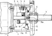
在图1中画出了本发明减速器的第一实施例。In FIG. 1 a first embodiment of the gear unit according to the invention is shown.
参考标号1表示一个同轴地固定在电机本体2前端部的一个机壳。电机本体2的转轴(输入轴)2a插在壳体1之中,用螺钉把一个转动体3固定在转轴2a的前端部。在转动体3上用螺纹连结着一个与转轴2a垂直的支承轴5,并用固定螺钉6把一个径向轴承4安装在支承轴5上。件3、4、和5和6共同构成一个压紧构件。与输入轴2a同心的输出轴7通过径向轴承9安装在机壳1的端盖8上。
参考标号10表示一个盘状传动构件,它由一块有弹性的薄板制成,用一个螺钉10a固定在输出轴7的一端,并在外圆周部分固定一个可绕枢轴回转的齿轮11。传动构件10将齿轮11和输出轴7连结在一起。图4A和或4B为传动构件10的前视图。用于螺钉10a的螺钉孔10b位于传动构件10的中心部分,而用于回转齿轮11的螺钉孔10c位于传动构件10的外圆周部分。回转齿轮11和螺钉孔10c通过螺钉连结在一起,输出轴7和螺钉孔10b也用螺钉连结在一起。在这些螺钉孔之间做出多个弓形孔10d或者半圆形孔10e,以便允许弯曲变形并防止圆周变形。
传动构件10由可弹性变形的材料例如金属或者合成树脂制成。The
在回转齿轮11圆环部分的一个表面上做出一个齿部(齿数为n1),该齿部接近于一个放射式伞形齿轮或者一个三角形齿的伞形齿轮,回转齿轮11被固定在传动构件10的外圆周部分上。齿轮11的齿部的另一个表面11a顶住径向轴承4的外圆周表面,并形成一个倾斜表面,以便与径向轴承4接触良好。回转齿轮11由适合的材料例如金属或者合成树脂制成。A tooth portion (the number of teeth is n1) is made on one surface of the ring portion of the
一个圆环状固定齿轮12通过一个块聚氨脂之类的弹性材料13固定在端盖8上,其齿部(齿数为n2)与回转齿轮11的齿部相对,但齿数与回转齿轮11的齿数不同。在由径向轴承4、支承轴5和固定螺钉6组成的压紧构件作用下,传动构件10产生弹性变形,使得回转齿轮11齿部的一些齿与固定齿轮12的齿部啮合。弹性材料13是用螺钉紧固、烤熔凝结或者用粘结剂固定在端盖8上的,因此,当回转齿轮11与固定齿轮12在压紧构件作用下产生啮合时,相互啮合的两个齿部不会产生任何齿隙。A ring-shaped fixed
在上述结构的本发明实施例中,当电机转轴2a转动时,由径向轴承4等组成的压紧构件,跟着转轴2a一起转动。径向轴承4使齿轮11朝输出轴方向向后倾斜,并且连续地压迫齿轮11端部的一个部分。于是,齿轮11的齿与固定在机壳1上的齿轮12的齿部连续地啮合,沿着一个环形轨迹运动,就是以这种方式,在使传动构件弹性变形的同时,使齿轮11绕枢轴运动。In the embodiment of the present invention with the above structure, when the
如果回转齿轮11的齿数n1为51,而固定齿轮12的齿数为50,两齿轮的齿数差为1,当回转齿轮11运动一整圈时,它就多啮合了一个齿,这个数值正好等于两齿轮齿数之差。也就是说,当电机转轴2a转动一整圈时,回转齿轮11转动1/50圈。把齿轮11,12连结在一起的传动构件10在绕枢轴运动期间以其弹性力吸收弯曲应变,并准确地将转动传递给输出轴7。此外,在位于固定齿轮12和端盖8之间的弹性材料圈13的作用下,由组成传送构件的零件的允许误差,装配调整引起的任何齿隙均能消除。If the number of teeth n1 of the
图2画出本发明的第二实施例。Figure 2 shows a second embodiment of the invention.
在上述第一实施例中,压紧装置是由径向轴承4、支承轴5以及固定螺钉6组成的。而在第二实施例中,电机转轴2a上固定着一个圆筒形压紧构件20,压紧构件20的开口端表面20a做成斜切端面状,并顶住回转齿轮11的另一个侧面,以便齿轮11顺次地与固定齿轮12的一段齿部啮合。In the above-mentioned first embodiment, the pressing device is composed of the
在压紧构件20的开口端表面20a可安装一个止推轴承,以便减小相对于固定齿轮12的滑动阻力。On the
同样地,压紧构件20以及回转齿轮11可都用金属制成,也可用不同的材料制造,例如:在大扭矩变速时可用一种金属和合成树脂做成,以防烧毁。而在小扭矩变速时可用不同的合成树脂做成,也就是说,要根据用途选择适当的材料。Likewise, the pressing
此外,在上述第一和第二实施例中,装有压紧构件的输入转动体是通过一个平衡块之类(未画出)保持转动平衡的。Furthermore, in the first and second embodiments described above, the input rotary body provided with the pressing member is kept in rotational balance by a weight or the like (not shown).
图2画出本发明的第三实施例。Fig. 2 shows a third embodiment of the present invention.
在上述第一第二实施例中,只是依靠传动构件10的弹性力,使回转齿轮11倾斜,顺次完成绕枢轴的运动,而在本实施例中,在输出轴7的一个端部做出一个半球形块22,而齿轮11上装有一个接纳件23。接纳件23上的孔23a与半球形块22配合。In the above-mentioned first and second embodiments, only the elastic force of the
因此,上文提及的回转齿轮11的绕枢轴运动能由与半球形块22配合的接纳件23加以控制,从而得到稳定的绕枢轴运动。Therefore, the above-mentioned pivoting movement of the
在上述几个实施例中,使用径向轴承4以及圆筒形压紧构件20作为压紧装置,但本发明不受此限制,球之类也可使用。In the above several embodiments, the
此外,在上述几个实施例中,传动构件的零件采用螺钉连结,在大量生产中,可根据所用的成形工艺,考虑整体成形、嵌入连结之类方法。In addition, in the above several embodiments, the parts of the transmission components are connected by screws. In mass production, methods such as integral forming and embedded connection can be considered according to the forming process used.
现在参照图7至9,介绍上述实施例的改进形式。此处只介绍上述实施例的改进之处。这些改进后的实施例与上述实施例的区别在于:对弹性构件14的处置作了精心的设计。所述弹性构件14由橡胶或者聚氨脂之类的弹性材料制成,并适于直接顶住齿轮11的一部分。Referring now to Figures 7 to 9, modifications of the above-described embodiment will be described. Only the improvements of the above embodiments are introduced here. The difference between these improved embodiments and the above-mentioned embodiments is that the handling of the
因此,当回转齿轮11与固定齿轮12啮合时,也顶住弹性构件14的一部分,使弹性构件14产生弹性变形,从而能清除两个齿轮之间的齿隙,并减少震动和噪声。Therefore, when the
图10至12画出了进一步改进的情况。与原先实施例的相同之处不再描述,只介绍改进的不同之处。Figures 10 to 12 illustrate further improvements. The same parts as the previous embodiment are not described, and only the improved differences are introduced.
参考标号15表示一个用橡胶或者聚氨脂之类弹性材料制成的圆环状固定齿轮,用烤熔凝结或者粘结剂将它固定在端盖8上。这个固定齿轮15的齿部(齿数为n2)与回转齿轮11的齿部相对,但是它的齿数与齿轮11的齿部齿数不同。在由径向轴承4、支承轴5以及固定螺钉6组成的压紧构件作用下,回转齿轮11的齿部使传动构件10朝着固定齿轮12的齿部弹性变形,使齿轮11的一些齿与固定齿轮12的齿部啮合。由于齿轮12由弹性材料制成,当回转齿轮11在压紧构件作用下与固定齿轮12啮合时,两个齿轮的齿部啮合将不会有任何齿隙。回转齿轮11也可用橡胶或者聚氨脂之类弹性材料制成,或者做成O型环等形状,以便取得类似效果。
因此,由于组成传动构件的零件的允许误差,安装调整等造成的任何齿隙,将借助于由弹性材料制成的固定齿轮12在厚度方向的弹性变形而被消除掉,并且也减少了震动和噪声的生成。Therefore, any backlash caused by the allowable error of the parts constituting the transmission member, installation adjustment, etc., will be eliminated by means of the elastic deformation of the fixed
在图13至15中介绍又一次改进后的实施例。A further modified embodiment is presented in FIGS. 13 to 15 .
在上文所述的每一个实施例中,已介绍了一种装置,在这种装置中,大变速比是通过齿轮间的啮合或者齿轮与弹性构件之间的接触而获得的。In each of the embodiments described above, there has been described a device in which a large gear ratio is obtained by meshing between gears or contact between the gears and the elastic member.
而在下面将要介绍的一种装置中,大变速比是通过两者的相互摩擦接触而获得的。与原先实施例相同的部分不再重复,只介绍不同的部分。In a device to be described below, however, the large gear ratio is obtained by the mutual frictional contact of the two. The parts that are the same as those in the previous embodiment will not be repeated, and only the different parts will be introduced.
在图13至15中,一个绕枢轴回转的构件11a具有一个环状摩擦构件16,该摩擦构件用橡胶或者聚氨脂之类弹性材料制成,并用烤熔凝结或者用粘结剂固定在一个圆环状边缘部分上。所述边缘部分的后侧面顶住径向轴承4的外圆周表面,并将后侧面做成一个倾斜表面,以便更好地顶住径向轴承4。In Figs. 13 to 15, a pivoting
而圆环状固定构件17用橡胶或者聚氨脂之类弹性材料制成并用烤熔凝结或者用粘结剂固定在端盖8上。这个固定构件17与摩擦构件16相对,但接触长度与摩擦构件16不相等。在由径向轴承4、支承轴5以及固定螺钉6构成的压紧构件作用下,摩擦构件16使传动构件10朝着固定构件17弹性变形,从而导致摩擦构件16的一个部分与固定构件17摩擦接触。And the ring-shaped fixing
在这种结构的实施例中,当电机本体2的转轴2a转动时,由径向轴承4等组成的压紧构件也随之转动。径向轴承4使摩擦构件16与固定在机壳上的固定构件17产生摩擦接触,以便在压迫摩擦构件16端部导致传动件10弹性变形的同时,使摩擦构件16绕枢轴运动。当转轴2a运动一整圈时,回转构件11a转动一个值,此值等于上述的接触长度之差。In the embodiment of this structure, when the
在下面将要介绍一个实施例,其减速器基本原理与上述各实施例相同,只是机构上有一些差别。An embodiment will be introduced below, the basic principle of the speed reducer is the same as that of the above-mentioned embodiments, but there are some differences in mechanism.
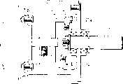
图16、17画出本发明的另一种形式。Figures 16 and 17 illustrate another form of the invention.
参考标号101表示该变速器的机壳,它的一端用螺钉固定在电机102上,一根输出轴106从它的另一端伸出。输出轴106通过一个第一径向轴承107a和一个第二径向轴承107b可转动地支承在机壳101上;固定齿轮114的齿部朝向电机102侧,用一安装螺钉115固定;在安装时输出轴106和固定齿轮114的轴线不仅要与电机102的转轴102a同心,还要与机壳内壁表面形成的控制部分101a同心,以便控制回转齿轮110在运动时产生的偏心量。所述回转齿轮110也是同心设置的,在下文中将作介绍。在机壳伸出端一侧装有一个E型防错动环109,防止输出轴106错动,在机壳和防错动环之间还设置一个齿隙调整垫片108。Reference numeral 101 denotes a case of the transmission, one end of which is screwed to a
电机本体102的转轴(输入轴)102a插入机壳101之中,一个转动体103通过螺钉固定在转轴102a的顶端。也可采用压入法或者粘结法将转动体103固定在转轴102a上。一个第一支承轴105a和一个第二支承轴105b按照垂直于转轴102a的方向,固定在转动体103的直径两端。A rotating shaft (input shaft) 102a of the
此外,第一支承轴105a和第二支承轴105b在直径方向是等距的,但在轴线方向(推动方向)具有一个偏离值d。在第一支承轴105a和第二支承轴105b的顶端,分别可转动地安装着由径向轴承构成的等直径第一压紧滚子104a和第二压紧滚子104b;转动体103、压紧滚子104a、104b连同支承轴105一起组成一个压紧构件,以便压迫回转齿轮110(下文将别作介绍)的一部分顶住固定齿轮114。转动平衡调整能用来稳定压紧构件的转动,使压紧构件的转动不会产生不平衡,这种转动平衡调整可借助上文所述的偏离值来实现。Furthermore, the first support shaft 105a and the second support shaft 105b are equidistant in the diameter direction, but have an offset value d in the axial direction (pushing direction). At the tops of the first supporting shaft 105a and the second supporting shaft 105b, the equal-diameter first pressing roller 104a and the second pressing roller 104b made of radial bearings are rotatably installed respectively; The tight rollers 104a, 104b together with the support shaft 105 form a pressing member for pressing a part of the rotary gear 110 (not to be described later) against the fixed gear 114 . The rotation balance adjustment can be used to stabilize the rotation of the pressing member, so that the rotation of the pressing member will not be unbalanced, and this rotation balance adjustment can be realized by means of the above-mentioned offset value.
偏离值d是根据所需倾斜度来设定的,这一倾斜度应能顺次地使回转齿轮110的一部分与固定齿轮114的齿部啮合。也就是说,第一压紧滚子104a的位置比第二压紧滚子104b更加靠近回转齿轮110,因此,当回转齿轮110顶住第一压紧滚子104a和第二压紧滚子104b时,它相对于转轴102a而言变成倾斜的。上文所述的偏离值d也可为零,而由第一压紧滚子104a和第二压紧滚子104b的不同直径来提供不同的偏离值d。在与压紧滚子104a、104b相对的回转齿轮背面上做出一个圆环形凸缘110a,此凸缘具有一个顶住压紧滚子104a、104b的倾斜表面,该倾斜表面能保证更好地顶住两个滚子。The offset value d is set according to the desired inclination which can sequentially engage a portion of the
在回转齿轮110的圆环状本体的一个表面上做出一个齿部(齿数为n1),该齿部接近于一个放射式伞形齿轮或者一个三角形齿的伞形齿轮,如图17所示,并且,回转齿轮110由适合的材料例如金属或者合成树脂做成。On one surface of the annular body of the
而且,回转齿轮110通过一个具有对准功能的接合在机构安装在输出轴106上。所述接合机构能把回转齿轮110的转动传递给输出轴106,在本实施例中,它由一个盘状传动构件113、一对第一连结销111以及一个对第二连结销112构成,所述传动构件113用弹性薄板做成,第一连结销111从输出轴上伸出并与传动构件113啮合,而第二连结销112是由齿轮110提供的。在传动构件113的外圆周上做出U形槽113a和113b,它们沿直径方向间隔90°分布,第一连结销111与两个相对的U形槽113a啮合,而第二连结销112与另外两个相对的U形槽113b啮合,第一连结销111、第二连结销112与U形槽的啮合段做成锥形,并这些啮合段的锥形表面的作用下,传动构件113能绕枢轴回转,并且在将U形槽连结在一起的方向没有任何间隙。也就是说,构成接合机构的一对第一连结销111被固定在输出轴106上,而一对第二连结销112被固定在回转齿轮110上,并且每对连结销的锥形段被设计成从传动构件113的前面和后面压紧它并使它弹性变形,因此,在每个连结销和每个U形槽之间沿着输出轴转动方向的齿隙能够被消除。Also, the
因此,由于传动构件113绕枢轴运动时倾斜,也由于传动构件113在转动方向的刚度,即使回齿轮110在绕枢轴运动的同时转动,它在绕枢轴运动时的倾斜也是允许的。回转齿轮110的转动通过第一连结销111以及第二连结销112被传递到输出轴106上。传动构件113上做出多个U形槽,这些槽与连结销111和112的锥形段啮合,另一种办法是用长孔来替代U形槽。Therefore, due to the inclination of the transmission member 113 when pivoting, and due to the stiffness of the transmission member 113 in the rotational direction, even if the
固定齿轮114大致呈圆环形,其齿部(齿数为n2)的齿数与回转齿轮110的齿数不同,并适于与受到上述压紧构件压迫的回转齿轮110的一部分啮合。The fixed gear 114 has a substantially circular shape, has a tooth number (n2 ) different from that of the
在结构如同上文所述的本实施例中,当电机转轴102a转动时,由压紧滚子104a、104b等组成的压紧构件也随之旋转。压紧滚子104a、104b向后压迫回转齿轮110的环形凸缘110a。由于第一压紧滚子104a(压紧段)与第二压紧滚子104b(支承段)相比,处于更加靠近回转齿轮110的位置,回转齿轮110处于倾斜位置,此时,它围绕输出106的轴线回转运动,使被第一压紧滚子104a推进区段的齿部与固定齿轮114的齿部啮合。此时,第二压紧滚子104b也顶住回转齿轮110的凸缘110a,使回转齿轮110的震动受到抑制,从而获得了无噪声无震动的转动。In the present embodiment having the structure as described above, when the motor shaft 102a rotates, the pressing member composed of the pressing rollers 104a, 104b, etc. also rotates accordingly. The pressure rollers 104a, 104b press the annular flange 110a of the
啮合位置随第一压紧滚子104a的转动而变化,在此时,接合机构的弹性变形以及连结销111、112凸部锥形表面的作用能产生对准运动,以便消除在绕枢轴回转期间的轴线偏离和倾斜,因此,能保证回转齿轮110进行精确的绕枢轴运动,将转动精确地传递给输出轴110,并消除了所有齿隙。The engagement position changes with the rotation of the first pinch roller 104a, at this time, the elastic deformation of the engagement mechanism and the action of the conical surface of the protrusions of the connecting pins 111, 112 can produce an alignment movement so as to eliminate the pivoting movement. During the axis deviation and inclination, therefore, can ensure that the
如果回转齿轮110的齿数n1为51,固定齿轮114的齿数为50,两齿轮的齿数差为1,所以当回转齿轮110运动一整圈时,它多啮合了固定齿轮114一个齿,这个数值正好等于两齿轮齿数之差。也就是说,当电机转轴102转动一整圈时,回转齿轮110转动1/50圈。连结销111和112除了做成锥形之外,还可以做成直的,此时,可将具有锥形内周边的啮合部分做在传动构件113的长孔或U形槽的侧面上。If the number of teeth n1 of the
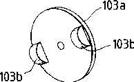
在本实施中,使用径向轴承构成的压紧滚子作为压紧构件的压紧件,然而,也可使用树脂之类材料做成的滚子,如图18A所示,在一个盘状可转动构件103a上做出一对半圆柱体的凸块103b或者是做出一对半球形凸块,要求凸块材料的摩擦系数小并具有良好的抗磨性能。In this embodiment, a pressing roller made of a radial bearing is used as a pressing part of the pressing member, however, a roller made of a material such as resin may also be used, as shown in FIG. 18A, in a disc shape. A pair of
此外,也可采用图18B所示的双滑块转动机构作为连结构件。In addition, the double-slider rotation mechanism shown in FIG. 18B can also be used as the connecting member.
这个双滑块转动机构由一个固定在回转齿轮110上的输入毂盘171、一个固定在输出轴106上的输出毂盘172以及一个隔盘173组成,隔盘173与输入毂盘171和输出毂盘172啮合,输入毂盘171和输出毂盘172分别具有一个第一J形凸块171a和一个第二I形凸块172a,两凸块从毂般171、172的相对表面沿着与转动轴线L垂直的方向伸出,而隔盘173也呈盘状并具有一个第一咬合槽173a和一个第二咬合槽173b,这两个咬合槽背靠背相互垂直并与转动轴线L正交。输入毂盘171的第一凸块171a与第一咬合槽173a咬合,而输出毂盘172的第二凸块172a与第二咬合槽173b咬合。This double slider rotating mechanism is made up of an input hub 171 fixed on the
在这种构造的接合机构中,输入毂盘171和隔盘173可按箭头A方向相互滑动,而隔盘173和输出毂盘172可按箭头B方向相互滑动。输入毂盘171固定在回转齿轮110上,但它可以绕X轴线运动以及绕Y轴线运动,因此,回转齿轮110的转动能稳定地传送给输出轴106。In the engagement mechanism of this configuration, the input hub 171 and the spacer 173 are mutually slidable in the arrow A direction, and the spacer 173 and the output hub 172 are mutually slidable in the arrow B direction. The input hub 171 is fixed to the
特别是在一个回转齿轮110转速高的大速比减速器中或者是在要求转动噪声小的减速器中,回转齿轮110和固定齿114的齿能用下述方法成形:先使绕枢轴运动的角度减小,然后把标准齿轮的顶圆直径修整掉顶圆直径和节圆直径差值的1/3左右,以便将沿着推动方向的震动减少到最大限度。此外,为了最大限度地抑制由于回转齿轮110绕枢轴运动产生的震动,要求加宽轴承107a和107b的间距,例如,为达此目的,可将轴承107a的一侧留在机壳101内,而将其另一侧放在减速器外部,并可进一步把传动构件做成轴承之间的一个齿轮,从而不需传送构件就能输出(未特别画出)。Especially in a speed reducer with a high rotational speed of the
图19画出一个经过改进的实施例。Figure 19 shows a modified embodiment.
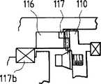
在这个实施例中,采用烤熔凝结法或者粘结剂,在与回转齿轮110啮合的固定齿轮116的一段齿部上,固定一个弹性材料圈117,圈117可用橡胶或者聚氨脂之类制成。当然,也可在回转齿轮110的一个部分上做出这种橡胶或者聚氨脂之类的弹性材料圈。In this embodiment, an
当回转齿轮110在压紧构件作用下与固定齿轮116啮合时,两个齿轮的齿部啮合,在此同时,回转齿轮110也顶住弹性材料圈117的承载部分并使后者弹性变形,从而能够消除两齿轮之间的齿隙,并减少震动和噪声的生成。弹性材料圈117的承载面(齿面)大致呈伞齿、三角形齿、平面等形状。When the
图20画出另一个经过改进的实施例。Fig. 20 shows another modified embodiment.
在这个实施例中,固定齿轮和回转齿轮之一用橡胶或者聚氨脂之类的弹性材料制成,在图20中是圆环形固齿轮118由弹性材料做成,并用烤熔凝结法或者粘结剂固定在机壳101上。In this embodiment, one of the fixed gear and the rotary gear is made of an elastic material such as rubber or polyurethane. In FIG. The adhesive is fixed on the casing 101 .
当回转齿轮110在压紧构件(与图16实施例所示压紧构件相同)作用下与固定齿轮118啮合时,两齿轮间的任何齿隙均能被消除,生成的震动和噪声也被减少。也可以是回转齿轮用弹性材料制成,要求这个弹性齿轮的承载面大致呈伞齿,三角形齿或者一个简单平面等形状。When the
图21画出又一个经过改进的实施例。Figure 21 shows yet another modified embodiment.
在这个实施例中,固定齿轮118用一种弹性材料制成,而回转齿轮的齿部119a也用橡胶或者聚氨脂之类的弹性材料制成,而且齿部119a用烤熔凝结或者粘结法固定在回转构件119上。In this embodiment, the fixed gear 118 is made of an elastic material, and the tooth portion 119a of the rotary gear is also made of an elastic material such as rubber or polyurethane, and the tooth portion 119a is solidified or bonded by baking. fixed on the rotating member 119.
当回转齿轮在压紧构件(与图16实施例所示压紧构件相同)作用下与固定齿轮118啮合时,两齿轮间的任何齿隙均能被消除,生成的震动和噪声也被减少。要求这个弹性齿轮的承载面大致呈伞齿,三角形齿或者一个简单平面等形状。When the rotary gear meshes with the fixed gear 118 under the action of the pressing member (the same as the pressing member shown in the embodiment of Fig. 16), any backlash between the two gears can be eliminated, and the generated vibration and noise are also reduced. It is required that the load-bearing surface of the elastic gear is roughly in the shape of bevel teeth, triangular teeth or a simple plane.
图22至26表示本发明变速器用镜头驱动(如光学拍摄镜头的对焦、变焦或光圈控制等)机构的情况,图22画出安装在一台图23电视摄像机C上的拍摄镜头D。Fig. 22 to 26 represent the situation of the lens drive (as the focusing, zooming or aperture control etc. of optical shooting lens) mechanism of speed changer of the present invention, and Fig. 22 draws and is installed on the shooting lens D on the TV camera C of a Fig. 23.
在图22中,参考标号50、51、52、53和54分别表示镜头体、驱动装置、对焦环、变焦环和光圈环。驱动装置的输出齿轮(未画出)与这些环的外圆周上做出的齿部啮合,从而能传送转动输出。In FIG. 22, reference numerals 50, 51, 52, 53, and 54 denote a lens body, a driving device, a focus ring, a zoom ring, and an aperture ring, respectively. An output gear (not shown) of the driving means meshes with teeth formed on the outer circumference of these rings so that a rotational output can be transmitted.
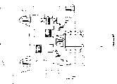
图24和25画出图22驱动装置中的变焦动力传递装置,其中,图24描述用减速器驱动镜头时的动力传递途径,而图25表示手动驱动操作环的状态。24 and 25 show the zoom power transmission device in the driving device of FIG. 22, wherein, FIG. 24 describes the power transmission path when the lens is driven by a reducer, and FIG. 25 shows the state of the manual driving operation ring.
在图24中,除了镜头筒和操作环以外的构件都被包括在本驱动装置之中。In FIG. 24, members other than the lens barrel and the operation ring are included in the drive device.
在这几张图中,参考标号55为镜头操作环,在它的外圆周表面上做出沿着圆周方向的啮合齿55a。变速器56与电机66做成整体,一个台阶形套筒58安装在从变速器机壳伸出的输出轴57上,并用一个销子59固定住,因此套筒58能随输出轴57转动。In these figures,
参考标号60为变速器56的输出齿轮。它用来相对于套筒58转动,并且通常由弹簧62通过可滑动垫圈61推向电机66一侧。在这种结构中,当负载扭矩小于预定值时,变速器56的输出齿轮60和输出轴57象一个零件那样转动;而当负载钮矩过大时,输出齿轮60相对于变速器56的套筒58打滑,起到扭矩限制器的作用,从而能减少作用于齿面的力,防止齿面损坏。
在停止时,特别是镜头被高速驱动到它的操作端部时,这种扭矩限制器能有效地吸收施加在齿面的冲击力。This torque limiter can effectively absorb the impact force applied to the tooth surface when stopping, especially when the lens is driven to its operating end at high speed.
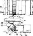
一个中间齿轮63位于变速器56的输出齿轮60和操作环55之间。中间齿轮63可相对于一根轴64转动,在此同时还能在该轴上滑动。而且,中间齿轮63外圆周表面上的啮合齿63a与变速器输出齿轮60以及操作环55两者啮合。在配备这种动力传递机构时,拍摄者只需操纵该驱动装置上预定的操作开关,电机66产生的转动动力就能通过变速箱输出齿轮60和中间齿轮63传递到操作环55上,于是镜头就被电力驱动。An
图24画出手动操作环的情况。在这种情况下,当拍摄者操纵一个离合手柄(未画出)时,离合板65转动。与此同时,安装在离合板65上的一个转换销66与中间齿轮63接合,所以离合手柄的动作使中间齿轮63在轴64上滑动,并与变速器输出齿轮60脱离接触。因此,当手工操作镜头时,操纵离合手柄能中断驱动电机的动力传递通道,为了驱动镜头,只需直接手工拧动操作环或者扳动安装在操作环上的手柄即可。Figure 24 depicts the case of a manually operated ring. In this case, when the photographer manipulates a clutch handle (not shown), the
如上所述,本实施例采用了一种系统,当要选择转换电动驱动或者手动时,位于变速器输出齿轮60和操作环55之间并与它们啮合的中间齿轮63的位置发生移动,从而使啮合齿相互进入或者脱离啮合,在这种情况下,在外圆周表面上提供的啮合齿通常是正齿轮。As described above, the present embodiment employs a system in which the position of the
此外,在这个同时连结电机和镜头操作环的动力传递机构中,采用借助齿间啮合法传递动力的动力传递构件,以及限制传递扭矩以防止过载转动期间损伤齿面的扭矩限制器,两者也可作为无关系构件相互独立地被提供。In addition, in this power transmission mechanism that connects the motor and the lens operation ring at the same time, a power transmission member that transmits power by means of tooth meshing, and a torque limiter that limits the transmitted torque to prevent damage to the tooth surface during overload rotation are used, both of which are also used. Can be provided independently of each other as unrelated components.
由于在这个实施例中使用了本发明减速器,就可能获得没有齿隙的转动输出,并能取得阻断噪声和抑制震动的效果,在对焦、变焦、调光圈等操作时的响应性得到改善,在向上伸出时也能实现没有颤动的平滑运动。Since the speed reducer of the present invention is used in this embodiment, it is possible to obtain a rotational output without backlash, and can achieve the effect of blocking noise and suppressing vibration, and the responsiveness of operations such as focusing, zooming, and aperture adjustment is improved. , allowing smooth motion without judder when extending upwards.
图26画出了又一个实例。Fig. 26 shows yet another example.
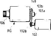
在上述每一个实施例中,减速器和电机102相互安装成整体,并且电机102的输出轴102a与减速器转动体103直接连结,而在本实施例中,电机102和减速器RG是相互分离的,电机102的转动可先通过一个减速机构来减速再传送到减速器RG,所述减速机构具有一个橡胶环或者同步带之类的动力传送构件149。该构件149套在转动体转轴103a的皮带轮103b和电机转轴102a的皮带轮102b上。In each of the above-mentioned embodiments, the reducer and the
根据本实施例,转动体103的转动能进一步被减速,变速操作产生的滑动声得到抑制,噪声、震动以及不规则转动都很小的变速操作得以实现。According to this embodiment, the rotation of the rotating body 103 can be further decelerated, the sliding sound generated by the shifting operation can be suppressed, and the shifting operation with less noise, vibration and irregular rotation can be realized.
在上文所述的每个实施例中,都把固定齿轮114和回转齿轮110用作变速差动构件,然而,一个摩擦盘也可用作变速差动构件,此时,摩擦转动承载位置的差值能作为变速输出。In each of the embodiments described above, the fixed gear 114 and the
在这种情况下,第一和第二变速差动构件本身不再变形,将第二变速差动构件的一部分做得能顺次地啮合或者顶住第一变速差动构件,以便获得大减速比。In this case, the first and second shift differential members themselves are no longer deformed, and a part of the second shift differential member is made to sequentially engage or bear against the first shift differential member in order to obtain a large deceleration Compare.
特别是,由于作为第一和第二变速差动构件的齿轮本身不再弹性变形,这种实施例也能应用于大扭矩变速并且传送效率高,用单级就能获得大减速比,而且传送效率与正齿轮的传送效率相当,从而能使减速器本身尺寸紧凑、结构简化。还有,由于零件数量减少,装配简单,制造成本也降低了。In particular, since the gears themselves as the first and second speed change differential members are no longer elastically deformable, this embodiment can also be applied to high torque speed change with high transmission efficiency, a large reduction ratio can be obtained with a single stage, and transmission The efficiency is equivalent to the transmission efficiency of the spur gear, so that the reducer itself can be compact in size and simplified in structure. Also, since the number of parts is reduced and assembly is simplified, the manufacturing cost is also reduced.
此外,本发明减速器的连结构件的结构也能进行简化。In addition, the structure of the coupling member of the speed reducer of the present invention can also be simplified.
按照本发明的另一种形式,能防止任何齿隙的产生。According to another form of the invention, any backlash can be prevented.
按照本发明,第二变速差动构件的过度偏心能被抑制,从而保证在一个适当范围内进行绕枢轴运动。According to the present invention, excessive eccentricity of the second transmission differential member can be suppressed, thereby ensuring pivotal movement within an appropriate range.
按照本发明,能精确地完成第二变速差动构件绕枢轴的运动,并能实现没有噪声和震动的变速操作。According to the present invention, the pivotal movement of the second shifting differential member can be accurately performed, and a shifting operation free from noise and vibration can be realized.
因此,按照本发明的另一种形式,有可能使装有这种减速器的驱动装置尺寸紧凑,而且,一个被驱动对象能没有任何齿隙地被驱动并实现大扭矩减速。Therefore, according to another form of the present invention, it is possible to make the drive unit equipped with the speed reducer compact in size, and furthermore, a driven object can be driven without any backlash and achieve high torque deceleration.
按照本发明的另一种形式的减速器,能应用于拍摄镜头或者照相机之类的光学仪器,使这些光学仪器结构紧凑,而且减少零件,容易装配,降低成本。此外,它还能十分精确地驱动长度焦镜头之类光学装置。Another form of reducer according to the present invention can be applied to optical instruments such as photographing lenses or cameras, making these optical instruments compact in structure, reducing parts, easy to assemble, and reducing cost. In addition, it drives optical devices such as telephoto lenses with great precision.
该减速器还能得到没有齿隙的转动输出,取得阻断噪声、抑制震动的效果,从而在对焦、变焦、控制光学装置光圈期间具有良好的响应性,而且在镜头向上伸出时也能得到没有颤动的运动。The speed reducer can also obtain a rotational output without backlash, and achieve the effect of blocking noise and suppressing vibration, so that it has good responsiveness during focusing, zooming, and controlling the aperture of the optical device, and can also be obtained when the lens is extended upward. No jerky movement.
Claims (17)
Translated fromChineseApplications Claiming Priority (18)
| Application Number | Priority Date | Filing Date | Title |
|---|---|---|---|
| JP325252/1994 | 1994-12-27 | ||
| JP325253/1994 | 1994-12-27 | ||
| JP325252/94 | 1994-12-27 | ||
| JP32525494AJP3568053B2 (en) | 1994-12-27 | 1994-12-27 | Transmission |
| JP325251/1994 | 1994-12-27 | ||
| JP325253/94 | 1994-12-27 | ||
| JP6325253AJPH08178005A (en) | 1994-12-27 | 1994-12-27 | Gearbox |
| JP325251/94 | 1994-12-27 | ||
| JP325254/94 | 1994-12-27 | ||
| JP32525294AJP3566366B2 (en) | 1994-12-27 | 1994-12-27 | Transmission |
| JP6325251AJPH08177985A (en) | 1994-12-27 | 1994-12-27 | Gearbox |
| JP325254/1994 | 1994-12-27 | ||
| JP260165/95 | 1995-10-06 | ||
| JP260165/1995 | 1995-10-06 | ||
| JP7260165AJPH09101445A (en) | 1995-10-06 | 1995-10-06 | Shooting lens and camera |
| JP310897/1995 | 1995-11-29 | ||
| JP310897/95 | 1995-11-29 | ||
| JP7310897AJPH09151999A (en) | 1995-11-29 | 1995-11-29 | Transmission, drive, and optical device |
Publications (2)
| Publication Number | Publication Date |
|---|---|
| CN1133953Atrue CN1133953A (en) | 1996-10-23 |
| CN1068418C CN1068418C (en) | 2001-07-11 |
Family
ID=27554284
Family Applications (1)
| Application Number | Title | Priority Date | Filing Date |
|---|---|---|---|
| CN95120130AExpired - Fee RelatedCN1068418C (en) | 1994-12-27 | 1995-12-27 | Speed reducer |
Country Status (5)
| Country | Link |
|---|---|
| US (1) | US5893813A (en) |
| EP (1) | EP0719959B1 (en) |
| KR (1) | KR100189281B1 (en) |
| CN (1) | CN1068418C (en) |
| DE (1) | DE69511670T2 (en) |
Cited By (2)
| Publication number | Priority date | Publication date | Assignee | Title |
|---|---|---|---|---|
| CN104755801A (en)* | 2012-09-25 | 2015-07-01 | 佳能株式会社 | Gear mechanism, reducer and robot arm |
| TWI683067B (en)* | 2017-07-07 | 2020-01-21 | 日商日本電產新寶股份有限公司 | Reducer |
Families Citing this family (51)
| Publication number | Priority date | Publication date | Assignee | Title |
|---|---|---|---|---|
| JPH09197243A (en)* | 1996-01-11 | 1997-07-31 | Canon Inc | Transmission, drive, and optical device |
| US6648786B1 (en)* | 1999-09-09 | 2003-11-18 | Oechsler Aktiengesellschaft | Gearmotors |
| SI20549A (en)* | 2000-01-20 | 2001-10-31 | Milan Cizl | Gearwheel drive with swinging cone-shaped gearwheel |
| WO2002021017A1 (en)* | 2000-09-08 | 2002-03-14 | Iowa State University Research Foundation, Inc. | Self-actuating, traction-drive speed changer |
| JP3568919B2 (en)* | 2001-07-12 | 2004-09-22 | 正明 山下 | Transmission |
| US10285694B2 (en) | 2001-10-20 | 2019-05-14 | Covidien Lp | Surgical stapler with timer and feedback display |
| US7464847B2 (en) | 2005-06-03 | 2008-12-16 | Tyco Healthcare Group Lp | Surgical stapler with timer and feedback display |
| CA2609970C (en) | 2005-06-03 | 2014-08-12 | Tyco Healthcare Group Lp | Battery powered surgical instrument |
| US11291443B2 (en) | 2005-06-03 | 2022-04-05 | Covidien Lp | Surgical stapler with timer and feedback display |
| US7431188B1 (en) | 2007-03-15 | 2008-10-07 | Tyco Healthcare Group Lp | Surgical stapling apparatus with powered articulation |
| US8800837B2 (en) | 2007-04-13 | 2014-08-12 | Covidien Lp | Powered surgical instrument |
| US20080255413A1 (en) | 2007-04-13 | 2008-10-16 | Michael Zemlok | Powered surgical instrument |
| US7950560B2 (en) | 2007-04-13 | 2011-05-31 | Tyco Healthcare Group Lp | Powered surgical instrument |
| US11259801B2 (en) | 2007-04-13 | 2022-03-01 | Covidien Lp | Powered surgical instrument |
| US7823760B2 (en) | 2007-05-01 | 2010-11-02 | Tyco Healthcare Group Lp | Powered surgical stapling device platform |
| US7931660B2 (en) | 2007-05-10 | 2011-04-26 | Tyco Healthcare Group Lp | Powered tacker instrument |
| US20090090201A1 (en)* | 2007-10-05 | 2009-04-09 | Tyco Healthcare Group Lp | Nutating Gear Drive Mechanism for Surgical Devices |
| US7922063B2 (en) | 2007-10-31 | 2011-04-12 | Tyco Healthcare Group, Lp | Powered surgical instrument |
| DE102008008951B4 (en)* | 2007-12-10 | 2014-08-21 | Rolf Strothmann | Reduction gear |
| EP2278190B1 (en)* | 2009-05-22 | 2013-01-23 | National University Corporation Fukushima University | Deformation crown gear speed reduction mechanism |
| US8821514B2 (en) | 2009-06-08 | 2014-09-02 | Covidien Lp | Powered tack applier |
| WO2014076771A1 (en)* | 2012-11-13 | 2014-05-22 | 国立大学法人福島大学 | Crown gear deceleration mechanism |
| FR3020855A1 (en)* | 2014-05-12 | 2015-11-13 | Peugeot Citroen Automobiles Sa | REDUCER FOR THE STEERING ASSISTANCE OF A MOTOR VEHICLE, COMPRISING AN INCLINE TRAY PERFORMING ROTATIONS ON A FIXED TRACK |
| US10520063B2 (en)* | 2017-04-21 | 2019-12-31 | The Boeing Company | Mechanical virtual elliptical drive |
| US11311295B2 (en) | 2017-05-15 | 2022-04-26 | Covidien Lp | Adaptive powered stapling algorithm with calibration factor |
| US10987104B2 (en) | 2017-10-30 | 2021-04-27 | Covidien Lp | Apparatus for endoscopic procedures |
| US11207066B2 (en) | 2017-10-30 | 2021-12-28 | Covidien Lp | Apparatus for endoscopic procedures |
| US12185949B2 (en) | 2017-10-30 | 2025-01-07 | Covidien Lp | Apparatus for endoscopic procedures |
| US11497490B2 (en) | 2018-07-09 | 2022-11-15 | Covidien Lp | Powered surgical devices including predictive motor control |
| US12137902B2 (en) | 2018-07-25 | 2024-11-12 | Covidien Lp | Adaptive anti-twitch algorithm for powered surgical devices |
| US11197734B2 (en) | 2018-10-30 | 2021-12-14 | Covidien Lp | Load sensing devices for use in surgical instruments |
| US11369372B2 (en) | 2018-11-28 | 2022-06-28 | Covidien Lp | Surgical stapler adapter with flexible cable assembly, flexible fingers, and contact clips |
| US11202635B2 (en) | 2019-02-04 | 2021-12-21 | Covidien Lp | Programmable distal tilt position of end effector for powered surgical devices |
| US11376006B2 (en) | 2019-02-06 | 2022-07-05 | Covidien Lp | End effector force measurement with digital drive circuit |
| US11219461B2 (en) | 2019-03-08 | 2022-01-11 | Covidien Lp | Strain gauge stabilization in a surgical device |
| US10968969B2 (en)* | 2019-03-18 | 2021-04-06 | The Boeing Company | Nutational braking systems and methods |
| US11459098B2 (en) | 2019-11-27 | 2022-10-04 | The Boeing Company | Variable speed transmission and related methods |
| US11458244B2 (en) | 2020-02-07 | 2022-10-04 | Covidien Lp | Irrigating surgical apparatus with positive pressure fluid |
| KR102399888B1 (en)* | 2020-02-11 | 2022-05-20 | 서울대학교산학협력단 | Plate harmonic reducer |
| US11553913B2 (en) | 2020-02-11 | 2023-01-17 | Covidien Lp | Electrically-determining tissue cut with surgical stapling apparatus |
| US12029470B2 (en) | 2020-05-21 | 2024-07-09 | Covidien Lp | Simultaneous RF monopolar calibration using a shared return electrode |
| US11622768B2 (en) | 2020-07-13 | 2023-04-11 | Covidien Lp | Methods and structure for confirming proper assembly of powered surgical stapling systems |
| US12193884B2 (en) | 2020-11-17 | 2025-01-14 | Covidien Lp | Contactless force measurement of motor torque in powered surgical device |
| US11653919B2 (en) | 2020-11-24 | 2023-05-23 | Covidien Lp | Stapler line reinforcement continuity |
| US11744580B2 (en) | 2020-11-24 | 2023-09-05 | Covidien Lp | Long stapler reloads with continuous cartridge |
| US12016556B2 (en) | 2021-05-03 | 2024-06-25 | Covidien Lp | Handheld electromechanical surgical system |
| US11684362B2 (en) | 2021-06-07 | 2023-06-27 | Covidien Lp | Handheld electromechanical surgical system |
| US11771432B2 (en) | 2021-06-29 | 2023-10-03 | Covidien Lp | Stapling and cutting to default values in the event of strain gauge data integrity loss |
| US12161341B2 (en) | 2021-09-07 | 2024-12-10 | Covidien Lp | Slow speed staple and staple relaxation for stapling optimization |
| US11832823B2 (en) | 2022-02-08 | 2023-12-05 | Covidien Lp | Determination of anvil release during anastomosis |
| KR102616219B1 (en) | 2023-07-05 | 2023-12-20 | 주식회사 퓨트로닉 | two-stage speed reducer |
Family Cites Families (10)
| Publication number | Priority date | Publication date | Assignee | Title |
|---|---|---|---|---|
| US3587350A (en)* | 1969-06-18 | 1971-06-28 | Gen Motors Corp | Power transmission including friction drive and gear drive |
| DE2352016A1 (en)* | 1973-10-17 | 1975-04-30 | Vdo Schindling | TRANSMISSION FOR SMALL PERFORMANCE |
| IS988B6 (en)* | 1975-04-15 | 1978-03-08 | Balcke-Dürr AG. | Gear system |
| GB2011016A (en)* | 1977-12-22 | 1979-07-04 | Skf Nova Ab | Toothed Gearing |
| US4550630A (en)* | 1982-08-23 | 1985-11-05 | Allied Corporation | Hermetically sealed drive |
| DE3341558C2 (en)* | 1982-12-06 | 1986-08-21 | VEB Schwermaschinenbaukombinat Takraf -Stammbetrieb-, DDR 7010 Leipzig | Swash plate gear |
| JPS63194212A (en)* | 1987-02-09 | 1988-08-11 | Sony Corp | Lens driving device for camera |
| JPS63214544A (en)* | 1987-02-27 | 1988-09-07 | Sony Corp | Speed change mechanism |
| JPH04191546A (en) | 1990-11-27 | 1992-07-09 | Takaoka Electric Mfg Co Ltd | Speed reduction device |
| JPH0599283A (en)* | 1991-10-04 | 1993-04-20 | Takaoka Electric Mfg Co Ltd | Reducer |
- 1995
- 1995-12-26KRKR1019950056930Apatent/KR100189281B1/ennot_activeExpired - Fee Related
- 1995-12-27CNCN95120130Apatent/CN1068418C/ennot_activeExpired - Fee Related
- 1995-12-27DEDE69511670Tpatent/DE69511670T2/ennot_activeExpired - Lifetime
- 1995-12-27EPEP95120560Apatent/EP0719959B1/ennot_activeExpired - Lifetime
- 1997
- 1997-09-10USUS08/926,465patent/US5893813A/ennot_activeExpired - Fee Related
Cited By (2)
| Publication number | Priority date | Publication date | Assignee | Title |
|---|---|---|---|---|
| CN104755801A (en)* | 2012-09-25 | 2015-07-01 | 佳能株式会社 | Gear mechanism, reducer and robot arm |
| TWI683067B (en)* | 2017-07-07 | 2020-01-21 | 日商日本電產新寶股份有限公司 | Reducer |
Also Published As
| Publication number | Publication date |
|---|---|
| EP0719959B1 (en) | 1999-08-25 |
| KR960023919A (en) | 1996-07-20 |
| DE69511670T2 (en) | 2000-04-06 |
| KR100189281B1 (en) | 1999-06-01 |
| DE69511670D1 (en) | 1999-09-30 |
| US5893813A (en) | 1999-04-13 |
| EP0719959A1 (en) | 1996-07-03 |
| CN1068418C (en) | 2001-07-11 |
Similar Documents
| Publication | Publication Date | Title |
|---|---|---|
| CN1068418C (en) | Speed reducer | |
| CN1509382A (en) | Friction planetary transmission that converts rotary motion into reciprocating motion with reduced frequency | |
| CN1742175A (en) | Standard Rotary Actuator | |
| CN1306302C (en) | Lens apparatus and camera | |
| CN1246733C (en) | Lens cover assembly of cameru | |
| WO2023092701A1 (en) | Lens assembly and projection device | |
| WO2021134846A1 (en) | Electric motor having embedded reduction device | |
| JP2009258240A (en) | Lens driving mechanism and image pickup apparatus using the same | |
| CN1074813C (en) | Planetary gear reduction starter | |
| CN1497571A (en) | Optical disk device | |
| HK1050391B (en) | Continuous variable transmission | |
| JPH06160690A (en) | Lens barrel | |
| JP4038882B2 (en) | Autofocus lens barrel | |
| CN1254822C (en) | Optical disk device | |
| CN114466118B (en) | Panning or tilting head and imaging device | |
| CN109693757B (en) | Bicycle stepless automatic transmission | |
| JP2011133592A (en) | Lens barrel | |
| JPH09151999A (en) | Transmission, drive, and optical device | |
| JPH09197243A (en) | Transmission, drive, and optical device | |
| JPH0753053Y2 (en) | Lens barrel | |
| JPH1138307A (en) | Optical device | |
| CN1279679C (en) | External swing drive mechanism with bias motor | |
| CN113281948A (en) | Active focus following device for virtual film production | |
| JPH09101445A (en) | Shooting lens and camera | |
| CN221375163U (en) | Camera pan-tilt drive mechanism and motion device |
Legal Events
| Date | Code | Title | Description |
|---|---|---|---|
| C10 | Entry into substantive examination | ||
| SE01 | Entry into force of request for substantive examination | ||
| C06 | Publication | ||
| PB01 | Publication | ||
| C10 | Entry into substantive examination | ||
| SE01 | Entry into force of request for substantive examination | ||
| C14 | Grant of patent or utility model | ||
| GR01 | Patent grant | ||
| REG | Reference to a national code | Ref country code:HK Ref legal event code:GR Ref document number:1001875 Country of ref document:HK | |
| C17 | Cessation of patent right | ||
| CF01 | Termination of patent right due to non-payment of annual fee | Granted publication date:20010711 Termination date:20101227 |