CN113391508A - Wavelength conversion device, light source system and projection equipment - Google Patents
Wavelength conversion device, light source system and projection equipmentDownload PDFInfo
- Publication number
- CN113391508A CN113391508ACN202010177380.1ACN202010177380ACN113391508ACN 113391508 ACN113391508 ACN 113391508ACN 202010177380 ACN202010177380 ACN 202010177380ACN 113391508 ACN113391508 ACN 113391508A
- Authority
- CN
- China
- Prior art keywords
- light
- section
- wavelength conversion
- light source
- incident
- Prior art date
- Legal status (The legal status is an assumption and is not a legal conclusion. Google has not performed a legal analysis and makes no representation as to the accuracy of the status listed.)
- Pending
Links
Images


Classifications
- G—PHYSICS
- G03—PHOTOGRAPHY; CINEMATOGRAPHY; ANALOGOUS TECHNIQUES USING WAVES OTHER THAN OPTICAL WAVES; ELECTROGRAPHY; HOLOGRAPHY
- G03B—APPARATUS OR ARRANGEMENTS FOR TAKING PHOTOGRAPHS OR FOR PROJECTING OR VIEWING THEM; APPARATUS OR ARRANGEMENTS EMPLOYING ANALOGOUS TECHNIQUES USING WAVES OTHER THAN OPTICAL WAVES; ACCESSORIES THEREFOR
- G03B21/00—Projectors or projection-type viewers; Accessories therefor
- G03B21/14—Details
- G03B21/20—Lamp housings
- G03B21/2006—Lamp housings characterised by the light source
- G03B21/2033—LED or laser light sources
- G03B21/204—LED or laser light sources using secondary light emission, e.g. luminescence or fluorescence
- G—PHYSICS
- G02—OPTICS
- G02B—OPTICAL ELEMENTS, SYSTEMS OR APPARATUS
- G02B27/00—Optical systems or apparatus not provided for by any of the groups G02B1/00 - G02B26/00, G02B30/00
- G02B27/10—Beam splitting or combining systems
- G—PHYSICS
- G02—OPTICS
- G02B—OPTICAL ELEMENTS, SYSTEMS OR APPARATUS
- G02B27/00—Optical systems or apparatus not provided for by any of the groups G02B1/00 - G02B26/00, G02B30/00
- G02B27/10—Beam splitting or combining systems
- G02B27/1006—Beam splitting or combining systems for splitting or combining different wavelengths
- G—PHYSICS
- G03—PHOTOGRAPHY; CINEMATOGRAPHY; ANALOGOUS TECHNIQUES USING WAVES OTHER THAN OPTICAL WAVES; ELECTROGRAPHY; HOLOGRAPHY
- G03B—APPARATUS OR ARRANGEMENTS FOR TAKING PHOTOGRAPHS OR FOR PROJECTING OR VIEWING THEM; APPARATUS OR ARRANGEMENTS EMPLOYING ANALOGOUS TECHNIQUES USING WAVES OTHER THAN OPTICAL WAVES; ACCESSORIES THEREFOR
- G03B21/00—Projectors or projection-type viewers; Accessories therefor
- G03B21/14—Details
- G03B21/20—Lamp housings
- G03B21/208—Homogenising, shaping of the illumination light
Landscapes
- Physics & Mathematics (AREA)
- General Physics & Mathematics (AREA)
- Optics & Photonics (AREA)
- Engineering & Computer Science (AREA)
- Multimedia (AREA)
- Projection Apparatus (AREA)
Abstract
Translated fromChinese
Description
Translated fromChinese【技术领域】【Technical field】
本申请涉及光学投影领域,尤其涉及一种波长转换装置、光源系统及投影设备。The present application relates to the field of optical projection, and in particular, to a wavelength conversion device, a light source system and a projection device.
【背景技术】【Background technique】
在相关技术中,实现激光与荧光合光直接发出白光的典型方案主要有以下几种:In related technologies, the typical solutions to realize the direct emission of white light by laser and fluorescent light are mainly as follows:
一种方案是利用光学元件的区域透反特性,令分光合光镜的中心区域镀膜与周围区域 镀膜不同,其中,中心区域为透蓝反黄,而周围区域则在可见光波长范围全部反射。第一 光经过会聚透镜会聚后,在分光合光镜位置会聚成面积很小的一个光斑,从中心区域透射 过去,然后经过收集透镜,在波长转换装置上激发荧光。通过控制荧光材料的混合比例,可以使得部分蓝光激发荧光粉,转换为荧光,另外的一部分蓝光被散射成与荧光的光学扩展量相当的朗伯光,此时荧光与蓝光混合达到白平衡。此后,被散射的蓝光到达分光合光镜处;此时,周围区域的蓝光被反射进入后方光学系统,而中心区域的蓝光会透射过去损失掉。One solution is to make use of the regional transmission and reflection characteristics of optical elements to make the coating in the central region of the beam splitter different from the coating in the surrounding regions. After the first light is condensed by the condensing lens, it is condensed into a light spot with a small area at the position of the beam splitter, which is transmitted from the central area, and then passes through the collecting lens to excite fluorescence on the wavelength conversion device. By controlling the mixing ratio of fluorescent materials, part of the blue light can excite the phosphor and convert it into fluorescence, and another part of the blue light is scattered into Lambertian light equivalent to the etendue of the fluorescence. At this time, the fluorescence and blue light are mixed to achieve white balance. After that, the scattered blue light reaches the beam splitter; at this time, the blue light in the surrounding area is reflected into the rear optical system, and the blue light in the central area is transmitted and lost.
另一种方案是在分光合光镜的前表面镀一层蓝光分光膜,反射一部分蓝光,并透射另 一部分的蓝光,反射蓝光和透射蓝光的透反比例会影响光源最终出光的白光色坐标;分光 合光镜的后表面仍然是镀透蓝反黄的膜层。激光光源发出的激光束在分光合光镜的前表面 被分成透射的蓝光光束和反射的蓝光光束,其中透射的蓝光光束会在色轮处激发产生荧 光,荧光经分光合光镜反射进入后方光路;被分出来的反射的蓝光光束会被散射片散射成 朗伯光,被散射的蓝光光束到达分光合光镜。此时,被散射的蓝光光束会被再次分光,其 中部分蓝光透射过分光合光镜,作为蓝色基色光进入后方光路,而部分蓝光光束则因被反 射而损失掉。Another solution is to coat a blue light splitting film on the front surface of the beam splitter, which reflects part of the blue light and transmits another part of the blue light. The ratio of the reflected blue light to the transmitted blue light will affect the final white light color coordinate of the light source; points The rear surface of the photosynthetic mirror is still coated with a blue-to-yellow film. The laser beam emitted by the laser light source is divided into a transmitted blue light beam and a reflected blue light beam on the front surface of the beam splitter. The transmitted blue beam will be excited at the color wheel to generate fluorescence, and the fluorescence will be reflected by the beam splitter and enter the rear optical path. The separated reflected blue light beam will be scattered into Lambertian light by the scattering sheet, and the scattered blue light beam will reach the beam splitter. At this time, the scattered blue light beam will be split again, and part of the blue light will be transmitted through the beam splitter and enter the rear optical path as the blue primary color light, while part of the blue light beam will be lost due to reflection.
上述两种光源系统的方案中,在对第一光和荧光进行合光时,会不可避免的造成第一 光的损耗,降低了第一光的利用率,影响最终投影设备的显示效果。In the solutions of the above two light source systems, when the first light and the fluorescence are combined, the loss of the first light will inevitably be caused, the utilization rate of the first light will be reduced, and the display effect of the final projection device will be affected.
【发明内容】[Content of the invention]
本申请的目的在于提供一种波长转换装置、光源系统及投影设备,可减少光源系统的 光损耗。The purpose of the present application is to provide a wavelength conversion device, a light source system and a projection device, which can reduce the light loss of the light source system.
为了实现上述目的,一方面本申请提出一种波长转换装置,该波长转换装置包括第一 区段和第二区段,所述第一区段上设置有至少一个倾斜反射斜面,用于接收入射所述第一 区段的入射光并通过所述倾斜反射斜面令反射的出射光以不同于所述入射光的光路出射; 所述第二区段设置有波长转换材料,用于接收入射所述第二区段的入射光,并出射波长不 同所述入射光的出射光。In order to achieve the above object, on the one hand, the present application proposes a wavelength conversion device, the wavelength conversion device includes a first section and a second section, and the first section is provided with at least one inclined reflection slope for receiving incident light The incident light of the first section and the reflected outgoing light are emitted in a different optical path from the incident light through the inclined reflection slope; the second section is provided with a wavelength conversion material for receiving the incident light. The incident light in the second section emits outgoing light with wavelengths different from the incident light.
另一方面本申请提出一种光源系统,该光源系统包括第一光源组件、第一导光组件、 第一合光组件以及上述波长转换装置;其中,On the other hand, the present application provides a light source system, the light source system includes a first light source component, a first light guide component, a first light combining component, and the above wavelength conversion device; wherein,
所述第一光源组件用于发射第一光;the first light source assembly is used for emitting first light;
所述第一导光组件设置于第一光的传输路径上,用于将所述第一光引导至所述波长转 换装置;The first light guide assembly is arranged on the transmission path of the first light, for guiding the first light to the wavelength conversion device;
所述波长转换装置包括基于所述第一光不发生波长转换的第一区段,以及基于所述第 一光而出射第二光的第二区段;所述第一区段上设置有至少一个倾斜反射斜面,通过所述 倾斜反射斜面令反射的第一光以不同于入射至所述第一区段的第一光的光路入射至所述 第一合光组件;所述第二区段用于接收所述第一光并向所述第一合光组件出射所述第二 光;其中,所述第一光和所述第二光的波长范围不同;The wavelength conversion device includes a first section that does not undergo wavelength conversion based on the first light, and a second section that emits second light based on the first light; the first section is provided with at least an inclined reflection slope, through which the reflected first light is incident on the first light combining component in an optical path different from that of the first light incident on the first section; the second section for receiving the first light and outputting the second light to the first light combining component; wherein, the wavelength ranges of the first light and the second light are different;
所述第一合光组件接收所述经过所述倾斜反射斜面反射的第一光和所述第二光,并引 导至相同的出射光通道。The first light combining component receives the first light and the second light reflected by the inclined reflection slope, and guides them to the same outgoing light channel.
另一方面本申请提出一种投影设备,该投影设备包括光源子系统和光机子系统,其中, 所述光源子系统向所述光机子系统出射投影光,所述光机子系统接收所述投影光并基于所 述投影光进行调制形成与待显示画面对应的图像光,以使所述图像光能够在投影平面上显 示;其中,所述光源子系统为上述光源系统。On the other hand, the present application proposes a projection device, which includes a light source subsystem and an optomechanical subsystem, wherein the light source subsystem emits projection light to the optomechanical subsystem, and the optomechanical subsystem receives the projected light and generates a Based on the projection light, image light corresponding to the picture to be displayed is formed by modulating, so that the image light can be displayed on the projection plane; wherein, the light source subsystem is the above-mentioned light source system.
本申请的该波长转换装置包括第一区段和第二区段,所述第一区段上设置有至少一个 倾斜反射斜面,用于接收入射所述第一区段的入射光并通过所述倾斜反射斜面令反射的出 射光以不同于所述入射光的光路出射;所述第二区段设置有波长转换材料,用于接收入射 所述第二区段的入射光,并出射波长不同所述入射光的出射光。由此,可将入射至第一区 段后被反射光与第二区段出射的光以不同的光路从波长转换装置出射,进而可分别对被第 一区段反射的光与第二区段出射的光分别设计后方光路,令光路结构更加灵活,适应性强。The wavelength conversion device of the present application includes a first section and a second section, and the first section is provided with at least one inclined reflection slope for receiving incident light incident on the first section and passing through the first section. The inclined reflection slope makes the reflected outgoing light exit in an optical path different from the incident light; the second section is provided with a wavelength conversion material, which is used for receiving the incident light incident on the second section, and the outgoing wavelengths are different by different reasons. The outgoing light of the incident light. In this way, the reflected light after incident on the first section and the light emitted from the second section can be output from the wavelength conversion device in different optical paths, so that the light reflected by the first section and the second section can be respectively treated. The outgoing light is designed with the rear optical path, which makes the optical path structure more flexible and adaptable.
【附图说明】【Description of drawings】
为了更清楚地说明本申请实施例中的技术方案,下面将对实施例描述中所需要使用的 附图作简单地介绍,显而易见地,下面描述中的附图仅仅是本申请的一些实施例,对于本 领域普通技术人员来讲,在不付出创造性劳动的前提下,还可以根据这些附图获得其它的 附图,其中:In order to illustrate the technical solutions in the embodiments of the present application more clearly, the following briefly introduces the drawings that are used in the description of the embodiments. Obviously, the drawings in the following description are only some embodiments of the present application. For those of ordinary skill in the art, under the premise of no creative work, other drawings can also be obtained from these drawings, wherein:
图1为相关技术中的激光荧光光源系统第一实施例结构示意图;1 is a schematic structural diagram of a first embodiment of a laser fluorescent light source system in the related art;
图2为相关技术中的激光荧光光源系统第二实施例结构示意图;2 is a schematic structural diagram of a second embodiment of a laser fluorescent light source system in the related art;
图3a为本申请波长转换装置中第一区段的倾斜反射斜面一实施方式的结构示意图;3a is a schematic structural diagram of an embodiment of the inclined reflection slope of the first section of the wavelength conversion device of the present application;
图3b为本申请波长转换装置中第一区段的倾斜反射斜面另一实施方式的结构示意图;3b is a schematic structural diagram of another embodiment of the inclined reflection slope of the first section in the wavelength conversion device of the present application;
图3c为本申请波长转换装置中第一区段的倾斜反射斜面又一实施方式的结构示意图;3c is a schematic structural diagram of still another embodiment of the inclined reflection slope of the first section of the wavelength conversion device of the present application;
图3d为本申请波长转换装置中第一区段的倾斜反射斜面再一实施方式的结构示意图;3d is a schematic structural diagram of still another embodiment of the inclined reflection slope of the first section of the wavelength conversion device of the present application;
图4a为本申请波长转换装置一实施方式的结构示意图;4a is a schematic structural diagram of an embodiment of the wavelength conversion device of the present application;
图4b为本申请波长转换装置另一实施方式的结构示意图;4b is a schematic structural diagram of another embodiment of the wavelength conversion device of the present application;
图5为本申请光源系统一实施例的结构示意图;FIG. 5 is a schematic structural diagram of an embodiment of a light source system of the present application;
图6为图5所示的光源系统在另一视角下的结构示意图;6 is a schematic structural diagram of the light source system shown in FIG. 5 from another viewing angle;
图7为本申请光源系统中第一导光组件一实施方式的结构示意图;FIG. 7 is a schematic structural diagram of an embodiment of the first light guide assembly in the light source system of the present application;
图8为本申请光源系统另一实施例的结构示意图;FIG. 8 is a schematic structural diagram of another embodiment of the light source system of the present application;
图9为本申请光源系统又一实施例的结构示意图;FIG. 9 is a schematic structural diagram of another embodiment of the light source system of the present application;
图10为本申请投影设备一实施例的结构示意图。FIG. 10 is a schematic structural diagram of an embodiment of the projection apparatus of the present application.
【具体实施方式】【Detailed ways】
下面将结合本申请实施例中的附图,对本申请实施例中的技术方案进行清楚、完整地 描述,显然,所描述的实施例仅是本申请的一部分实施例,而不是全部的实施例。基于本 申请中的实施例,本领域普通技术人员在没有做出创造性劳动前提下所获得的所有其它实 施例,都属于本申请保护的范围。The technical solutions in the embodiments of the present application will be clearly and completely described below with reference to the accompanying drawings in the embodiments of the present application. Obviously, the described embodiments are only a part of the embodiments of the present application, rather than all the embodiments. Based on the embodiments in the present application, all other embodiments obtained by those of ordinary skill in the art without creative work fall within the protection scope of the present application.
现有技术中,通过采用以荧光反射镜作为分光合光元件对激发光进行分光,令部分激 发光被引导至波长转换装置以激发荧光材料产生荧光,另一部分激发光作为一种基色光, 进而令荧光和作为基色光的部分激发光在荧光反射镜处进行合光,从而实现激光与荧光合 光直接发出白光,通常采用的技术方案主要包括以下两种:In the prior art, a fluorescent mirror is used as a light-splitting and light-splitting element to split the excitation light, so that part of the excitation light is guided to a wavelength conversion device to excite the fluorescent material to generate fluorescence, and the other part of the excitation light is used as a primary color light, and then The fluorescence and part of the excitation light, which is the primary color light, are combined at the fluorescent mirror, so that the combined light of the laser and the fluorescent light can directly emit white light. The commonly used technical solutions mainly include the following two:
第一种技术方案如图1所示,荧光反射镜设置成区域镀膜的反射激光,其中心区域镀 膜镀透蓝反黄膜,而周围区域镀透射膜或增透膜。作为激发光的激光经过会聚透镜会聚后, 在荧光反射镜位置处会聚成面积很小的一个光斑,从荧光反射镜的中心区域透射,然后经 过收集透镜组,在波长转换装置上激发产生荧光。通过控制荧光材料的混合比例,可以使 得部分激光激发荧光粉,转换为荧光,另外的一部分激光被散射成与荧光的光学扩展量相 当的朗伯光,此时荧光与激光混合达到白平衡。此后,被散射的激光到达荧光反射镜处; 此时,入射荧光反射镜的周围区域的激光被反射进入后方光学系统,而入射荧光反射镜的 中心区域的激光会因透射而损失掉。The first technical solution is shown in Figure 1. The fluorescent reflector is set to reflect laser light with a regional coating. The central region is coated with a blue and yellow anti-yellow coating, and the surrounding region is coated with a transmissive or anti-reflection coating. After the laser as excitation light is condensed by the converging lens, it converges into a light spot with a small area at the position of the fluorescent reflector, transmits from the central area of the fluorescent reflector, and then passes through the collection lens group to be excited on the wavelength conversion device to generate fluorescence. By controlling the mixing ratio of fluorescent materials, part of the laser light can excite the phosphor powder and convert it into fluorescence, and another part of the laser light is scattered into Lambertian light with the etendue equivalent to the fluorescence. At this time, the fluorescence and the laser are mixed to achieve a white balance. After that, the scattered laser light reaches the fluorescent mirror; at this time, the laser light incident on the surrounding area of the fluorescent mirror is reflected into the rear optical system, and the laser light incident on the central area of the fluorescent mirror is lost due to transmission.
第二种技术方案如图2所示,荧光反射镜的面向激光光源的前表面镀了一层与激光对 应的分光膜,该分光膜可按预设分光比例反射一部分激光,并透射另一部分的激光,该预 设分光比例会影响光源最终出光的白光色坐标。以激光光源为蓝光为例,激光为蓝光,荧 光反射镜的朝向波长转换装置的后表面镀有透蓝反黄的膜层。激光光源发出的蓝光在荧光 反射镜的前表面以预设反光比例被分成透射的蓝光和反射的蓝光,其中透射的蓝光会在波 长转换装置处激发产生荧光,荧光经荧光收集透镜组收集后被荧光反射镜反射入后方光 路;被反射的蓝光则入射散射片,在散射片处被散射成朗伯光,被散射的蓝光经蓝光收集 透镜后入射荧光反射镜;此时,被散射的蓝光会被再次分光,其中一部分的蓝光透射过荧 光反射镜作为蓝色基色光进入后方光路,而另一部分蓝光光束则因被反射而损失掉。The second technical solution is shown in Figure 2. The front surface of the fluorescent reflector facing the laser light source is coated with a beam splitting film corresponding to the laser. The beam splitting film can reflect a part of the laser light and transmit another part of the Laser, the preset splitting ratio will affect the color coordinates of the final white light emitted by the light source. Taking the laser light source as blue light as an example, the laser light is blue light, and the rear surface of the fluorescent reflector facing the wavelength conversion device is coated with a blue-transmitting and yellow-transmitting film. The blue light emitted by the laser light source is divided into transmitted blue light and reflected blue light at a preset reflection ratio on the front surface of the fluorescent reflector. The transmitted blue light will be excited at the wavelength conversion device to generate fluorescence, and the fluorescence will be collected by the fluorescence collection lens group. The fluorescent reflector reflects into the rear light path; the reflected blue light enters the diffuser, where it is scattered into Lambertian light, and the scattered blue light enters the fluorescent reflector after passing through the blue light collecting lens; at this time, the scattered blue light will After being split again, a part of the blue light is transmitted through the fluorescent mirror and enters the rear light path as the blue primary color light, while the other part of the blue light beam is lost due to reflection.
上述的两种光源系统方案中,由于荧光反射镜对激发光始终是部分反射部分透射的, 因此在对蓝光和荧光进行合光时会不可避免的造成蓝光的损耗,降低了激发光的利用率, 减小投影设备的图像亮度,最终影响投影设备的显示效果。In the above two light source system solutions, since the fluorescent mirror always partially reflects and partially transmits the excitation light, the loss of blue light will inevitably be caused when the blue light and the fluorescence are combined, which reduces the utilization rate of the excitation light. , reduce the image brightness of the projection device, and ultimately affect the display effect of the projection device.
本实施例的波长转换装置包括第一区段和第二区段,所述第一区段上设置有至少一个 倾斜反射斜面,用于接收入射所述第一区段的入射光并通过所述倾斜反射斜面令反射的出 射光以不同于所述入射光的光路出射;所述第二区段设置有波长转换材料,用于接收入射 所述第二区段的入射光,并出射波长不同所述入射光的出射光。由此,可将入射至第一区 段后被反射光与第二区段出射的光以不同的光路从波长转换装置出射,进而可分别对被第 一区段反射的光与第二区段出射的光分别设计后方光路,令光路结构更加灵活,适应性更 强。The wavelength conversion device of this embodiment includes a first section and a second section, and the first section is provided with at least one inclined reflection slope for receiving incident light incident on the first section and passing through the first section. The inclined reflection slope makes the reflected outgoing light exit in an optical path different from the incident light; the second section is provided with a wavelength conversion material, which is used for receiving the incident light incident on the second section, and the outgoing wavelengths are different by different reasons. The outgoing light of the incident light. In this way, the reflected light after incident on the first section and the light emitted from the second section can be output from the wavelength conversion device in different optical paths, so that the light reflected by the first section and the second section can be respectively treated. The outgoing light is designed with the rear optical path, which makes the optical path structure more flexible and adaptable.
本申请提出一种波长转换装置,该波长转换装置上设置有多个区段,其中,第一区段 上可不设置波长转换材料,进而不会基于入射第一区段的光而发生波长转换;进一步,第 一区段上设置有至少一个倾斜反射斜面,第一区段可接收入射第一区段的光并通过倾斜反 射斜面令反射的光以不同于的光路出射。第二区段上具有波长转换材料,可基于入射第二 区段的光而发生波长转换材料,进而出射波段范围不同的光。The present application provides a wavelength conversion device, the wavelength conversion device is provided with a plurality of sections, wherein, the wavelength conversion material may not be provided on the first section, so that wavelength conversion will not occur based on light incident on the first section; Further, the first section is provided with at least one inclined reflection slope, and the first section can receive the light incident on the first section and make the reflected light exit in a different optical path through the inclined reflection slope. There is a wavelength conversion material on the second section, and the wavelength conversion material can be generated based on the light incident on the second section, so as to emit light with different wavelength bands.
如图3a至图3b所示,波长转换装置107上的第一区段的倾斜反射斜面可由具有倾斜 反射面的凸起结构构成,如图3a所示,可在波长转换装置107的第一区段上设置一个三角 形凸起结构,由三角形凸起结构的斜面作为该倾斜反射斜面;此外,也可如图3b所示,在波长转换装置107的第一区段上设置两个斜面相对于的三角形凸起结构,由两个三角形凸起结构的相对的两个倾斜面作为倾斜反射斜面。As shown in FIG. 3a to FIG. 3b, the inclined reflection slope of the first section of the
进一步,如图3c至图3d所示,波长转正装置107上的第一区段的倾斜反射斜面也可由在第一区段上设置的凹槽构成,凹槽的侧面相对于凹槽底面倾斜以构成第一区段上的倾斜反射斜面。如图3c所示,该凹槽可为三角形凹槽,三角形凹槽的倾斜面即可作为第一区段上的倾斜反射斜面。此外,也可如图3d所示,该凹槽也可为梯形凹槽,由梯形凹槽的 两个相对的倾斜反射斜面构成第一区段上的倾斜反射斜面。Further, as shown in FIGS. 3 c to 3 d , the inclined reflection slope of the first section on the
进一步,本实施例中波长转换装置107可为如图4a所示的板状波长转换装置或如图 4b所示桶形波长转换装置,第一区段A不基于入射的光进行波长转换,且设置有至少一倾 斜反射斜面,第二区域B中包含有波长转换材料,可基于入射的光而产生波长转换后出射 波段范围不同的光。本实施例中,波长转换装置107的第一区段A上的倾斜反射斜面在第一区段上可连续设置,如图7中的第一区段A上的阴影填充区域所示;在其他实施方式在,第一区段A上的倾斜反射斜面可对应于入射的光的脉冲时序间隔设置而间隔设置。Further, in this embodiment, the
进一步,本申请提出一种光源系统,该光源系统包括第一光源组件、第一导光组件、 波长转换装置及第一合光组件。第一光源组件用于出射第一光,第一光被第一导光组件引 导至波长转换装置;波长转换装置上设置有多个区段,其中,基于第一光不产生波长转换 的区段为第一区段,基于第一光产生波长转换而出射第二光区段为第二区段,其中,第二 光的波段范围与第一光的波段范围不同。波长转换装置连接有一驱动装置,波长转换装置 在驱动装置的驱动下周期性运动以使第一区段和第二区段时序的暴露于第一光的光路上。 进一步,第二区段设置有波长转换材料,当第二区段暴露于第一光的光路上时,被引导至 第二区段的第一光被波长转换材料吸收进而激发产生第二光;第一区段上设置有至少一个 倾斜反射斜面,当第一区段暴露于第一光的光路上时,被引导至第一区段的第一光入射在 至少一个倾斜反射斜面上被反射。本申请中,第一光相对于第一区段和第二区段的入射区 域均垂直入射,第二区段出射的第二光被垂直反射,第一区段反射的第一光则基于倾斜反 射斜面的以一倾角反射,由此第二区段出射的第二光和被反射的第一光在波长转换装置之 后的光路不重叠,以不同的光路被引导至第一合光组件处进行合光。其中,该波长转换装 置可为图3至图4所示的任意实施例的波长转换装置,具体结构请参见上述描述,此处不 再赘述。Further, the present application provides a light source system, which includes a first light source component, a first light guide component, a wavelength conversion device, and a first light combining component. The first light source component is used for emitting first light, and the first light is guided to the wavelength conversion device by the first light guide component; the wavelength conversion device is provided with a plurality of sections, wherein no wavelength conversion section is generated based on the first light For the first section, the wavelength conversion of the first light is generated and the second light section is emitted as the second section, wherein the wavelength range of the second light is different from the wavelength range of the first light. The wavelength conversion device is connected with a driving device, and the wavelength conversion device periodically moves under the driving of the driving device to expose the first section and the second section to the optical path of the first light in sequence. Further, the second section is provided with a wavelength conversion material, and when the second section is exposed to the optical path of the first light, the first light guided to the second section is absorbed by the wavelength conversion material and then excited to generate the second light; The first section is provided with at least one inclined reflection slope, and when the first section is exposed to the optical path of the first light, the first light guided to the first section is incident on the at least one inclined reflection slope and is reflected. In the present application, the first light is incident vertically with respect to the incident areas of the first section and the second section, the second light emitted from the second section is vertically reflected, and the first light reflected from the first section is tilted The reflection slope is reflected at an inclination angle, so that the optical paths of the second light emitted from the second section and the reflected first light after the wavelength conversion device do not overlap, and are guided to the first light combining component in different optical paths. Synthetic light. Wherein, the wavelength conversion device may be the wavelength conversion device of any of the embodiments shown in FIG. 3 to FIG. 4 . For the specific structure, please refer to the above description, which will not be repeated here.
其中,第一光和第二光能够合光形成彩色图像,即第一光和第二光合光后的光谱能够 包含三基色光的光谱;以第一光为蓝光为例,第二光可为黄光,或第二光可包括红光和绿 光。Wherein, the first light and the second light can be combined to form a color image, that is, the spectrum of the combined light of the first light and the second light can include the spectrum of the three primary color lights; taking the first light as blue light as an example, the second light can be The yellow light, or the second light, may include red light and green light.
本申请通过在第一区段上设置用于反射第一光的倾斜反射斜面,以使被反射的第一光 的光路不同于第二区段激发产生的第二光的光路,由此可在波长转换装置后分别引导第一 光和第二光入射至第一合光组件,在各自的光路中可不再设置波长选择元件、区域透射元 件或半反半透元件等分光元件,因此在第一光和第二光从波长转换装置出射到入射至第一 合光组件的过程中不会出现因光学元件的透反特性而导致的光损耗,可提高投影设备出射 的光亮度,提高显示质量。In the present application, an inclined reflection slope for reflecting the first light is arranged on the first section, so that the optical path of the reflected first light is different from the optical path of the second light generated by the excitation of the second section. After the wavelength conversion device respectively guides the first light and the second light to be incident on the first light combining component, the wavelength selection element, the area transmission element or the transflective element and other light splitting elements can no longer be arranged in the respective optical paths. When the light and the second light are emitted from the wavelength conversion device to the first light combining component, no light loss will occur due to the transflective characteristics of the optical element, which can improve the brightness of the light emitted by the projection equipment and improve the display quality.
本申请中,第一导光组件可为区域镀膜的二向色片,其包括中心区域和环绕中心区域 的周围区域,其中,中心区域镀有二向色膜,以使该中心区域能够反射与第一光的波长范 围对应的光,并透射其他波长范围的光;周围区域镀有透射面或增透膜,以使周围区域能 够透射所有波长范围的光。In the present application, the first light guide component may be an area-coated dichroic film, which includes a central area and a peripheral area surrounding the central area, wherein the central area is coated with a dichroic film, so that the central area can reflect and The light corresponding to the wavelength range of the first light transmits light in other wavelength ranges; the surrounding area is coated with a transmission surface or an anti-reflection film, so that the surrounding area can transmit light in all wavelength ranges.
本申请中,波长转换装置可为板状波长转换装置或桶形波长转换装置,且第一区段和 第二区段均可为多个,且多个第二区段可包括多个第二子区段,其中,多个第二子区段的 颜色可相同或不同,满足波长转换装置的第一区段反射的第一光和第二区段出射的第二光 的光谱范围至少覆盖三基色光的光谱范围即可,例如第二区段可仅为黄色区段,或第二区 段包括红色第二子区段、绿色第二子区段、黄色第二子区段、琥珀色第二子区段等。In the present application, the wavelength conversion device may be a plate-shaped wavelength conversion device or a barrel-shaped wavelength conversion device, and both the first segment and the second segment may be multiple, and the multiple second segments may include multiple second segments Sub-segments, wherein the colors of the plurality of second sub-segments can be the same or different, so that the spectral ranges of the first light reflected by the first segment of the wavelength conversion device and the second light emitted by the second segment cover at least three. The spectral range of the primary color light is sufficient. For example, the second segment may be only the yellow segment, or the second segment may include a red second sub-segment, a green second sub-segment, a yellow second sub-segment, and an amber second sub-segment. Second subsection, etc.
本申请中,第一光源组件出射的第一光入射第一导光组件的中心区域,在该中心区域 处被反射,并垂直入射至波长转换装置。在波长转换装置的第二区段,第一光被吸收并激 发波长转换材料产生出射的第二光,其中,第二光相对于波长转换装置垂直出射;在波长 转换装置的第一区段,第一光被倾斜反射斜面以一倾角反射进而相对于入射的第一光的光 路发生偏移。由此,被反射的第一光可避开第一导光组件的中心区域而被引导至第一合光 组件,即可避免第一光的光损耗,可提高投影设备出射的光亮度,提高显示质量。In the present application, the first light emitted from the first light source assembly enters the central area of the first light guide assembly, is reflected at the central area, and is vertically incident on the wavelength conversion device. In the second section of the wavelength conversion device, the first light is absorbed and excites the wavelength conversion material to generate an output second light, wherein the second light is perpendicular to the wavelength conversion device; in the first section of the wavelength conversion device, The first light is reflected by the inclined reflection slope at an inclination angle and then shifted relative to the optical path of the incident first light. In this way, the reflected first light can be guided to the first light combining component by avoiding the central area of the first light guide component, so that the light loss of the first light can be avoided, the brightness of the light emitted by the projection device can be improved, and the Display quality.
请一并参阅图5和图6,图5为本申请光源系统一实施例的结构示意图,图6为图5所示的光源系统在另一视角下的结构示意图。如图5和图6所示,本实施例的光源系统10 包括第一光源组件101、第一导光组件104、波长转换装置107及第一合光组件111。第一 光源组件101可包括多个光源,用于发射第一光,本实施例中以第一光为蓝光为例,第一 光源组件101可包括多个蓝光光源。其中,第一光源组件101包括的多个光源可为激光光 源、LED光源等。第一导光组件104设置于第一光源组件101出射的第一光的传输路径上, 用于将第一光引导至波长转换装置107。本实施例中,第一导光组件104可为区域镀膜的 二向色片,如图7所示,第一导光组件104包括中心区域1041和环绕中心区域1041的周 围区域1042,中心区域1041为镀有二向色膜层的镀膜区域,反射与蓝光波段的光,而透 射其他波段的光;周围区域1042镀有透射膜或增透膜,第一光源组件101出射的蓝光入 射至第一导光组件104的中心区域1041而被反射至波长转换装置107。Please refer to FIG. 5 and FIG. 6 together. FIG. 5 is a schematic structural diagram of a light source system according to an embodiment of the present application, and FIG. 6 is a structural schematic diagram of the light source system shown in FIG. 5 from another viewing angle. As shown in FIG. 5 and FIG. 6 , the
如图5和图6所示,可在第一导光组件104和波长转换装置107之间设置收集透镜组, 以对被第一导光组件104反射的第一光进行会聚进而令第一光以较小的光斑入射波长转换 装置107。本实施例中,蓝光经过第一导光组件104的中心区域1041反射后的光轴与收集 透镜组的光轴重叠。其中,收集透镜组可包括第一收集透镜105和第二收集透镜106。As shown in FIG. 5 and FIG. 6 , a collection lens group may be arranged between the first
进一步,本实施例中波长转换装置107上设置有多个区段,其中,基于蓝光不产生波 长转换的区域为第一区段,基于蓝光激发产生第二光的区段为第二区段。本实施例以第二 区段为一个黄色区段为例,黄色区段上包含有黄色荧光材料,能够吸收蓝光,在蓝光的激 发下产生并出射黄色荧光。波长转换装置107连接有一驱动装置(图中未示出),波长转换装置107在驱动装置的驱动下周期性运动以使第一区段和第二区段时序的暴露于蓝光的光路上。进一步,当第二区段经过蓝光的光路上时,被引导至第二区段的蓝光被波长装换装置的第二区段上的黄色荧光材料吸收,进而产生并出射黄色荧光;当第一区段经过蓝光的光束上时,被引导至第一区段的蓝光被第一区段上设置的至少一个倾斜反射斜面反射。其中,蓝光垂直入射波长转换装置107,第二区段出射的黄色荧光也相对于第二区段垂直出射,而被倾斜反射斜面反射的蓝光则以一倾角反射;由此,波长转换装置的第二区段出射的黄色荧光的出射光路相对于蓝激光的入射光路重叠,而被倾斜反射斜面反射的蓝光的光路与入射的蓝光的光路不重叠,进而令第二区段出射的黄色荧光和被第一区段反射的蓝光在波长转换装置107处被分离,以不同的光路出射,并分别被引导至第一合光组件111,在第一合光组件111处被合光。Further, in this embodiment, the
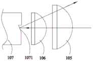
具体的,黄色荧光从波长装换装置的第二区段出射后经过收集透镜106、105,并透射 过第一导光组件104后入射至第一合光组件111,本实施例中,第一合光组件111为透黄反蓝的二向色片,由此黄色荧光可透射过第一合光组件111而进一步入射至匀光器件109。进一步参阅图6,图6中的箭头指示了蓝光被第一区段反射的光路,即蓝光入射第一区段后,被第一区段上设置的倾斜反射斜面1071反射,反射后的蓝光的光路与入射的蓝光的 光路不重叠,由此,反射后的蓝光不再经过第一导光组件104的中心区域,而是绕过第一 导光组件104或透射过第一导光组件104的周围区域,进而入射至第二导光组件110,被 第二导光组件110引导至第一合光组件111,蓝光进一步被第一合光组件111反射而进入 匀光器件109,由此,在第一合光组件111处实现蓝光和黄色荧光的合光。其中,第二导 光组件110可为反射镜110。Specifically, the yellow fluorescent light is emitted from the second section of the wavelength changing device, passes through the collecting
在该实施例中,由于从波长转换装置的第二区段出射的黄色荧光和被第一区段反射的 蓝光在波长转换装置处被分离,在共同入射第一合光组件之前在不同的光路中进行传输, 在各自的路径中不再设置波长选择元件、区域透射元件或半反半透元件等分光元件,因此 在黄色荧光和蓝光从波长转换装置出射到入射至第一合光组件的过程中,均不会出现因光 学元件的透反特性而导致的光损耗,提高光利用率,提高最终的光束亮度。In this embodiment, since the yellow fluorescent light emitted from the second section of the wavelength conversion device and the blue light reflected by the first section are separated at the wavelength conversion device, they are in different optical paths before being jointly incident on the first light combining component. During the transmission, the wavelength selective element, the area transmission element or the transflective element and other light splitting elements are no longer set in their respective paths, so the yellow fluorescence and blue light are emitted from the wavelength conversion device to the first light combining component. There is no light loss caused by the transflective characteristics of the optical elements, improving the light utilization rate and improving the final beam brightness.
本实施例中可采用多种方式设置第一区段上的倾斜反射斜面。本实施例以图3d所示 的梯形凹槽为例,其具有两个相对的两个倾斜反射斜面1071,如图6所示,第一光源组件101出射的蓝光被第一导光组件104的中心区域反射后沿收集透镜105、106的光轴垂直入射至第一个倾斜反射斜面1071,被第一个倾斜反射斜面1071反射至相对的第二个倾斜反射斜面1071,最终被第二个倾斜反射斜面1071反射后离开波长转换装置;由于第一个倾 斜反射斜面和第二个倾斜反射斜面的倾斜角均为45°;由此,蓝光被第二个倾斜反射斜面 反射后平行于收集透镜106、105的光轴出射,且相对于收集透镜106、105的光轴在光源 系统的厚度方向上发生了一定偏移;进一步,被反射的蓝光进入收集透镜106、105后基 于收集透镜106、105的会聚作用而发生光路偏移,令被反射的蓝光从第一导光组件104 的周围区域1042入射至反射镜110,或绕开第一导光组件104入射至反射镜110。In this embodiment, the inclined reflection slopes on the first section can be arranged in various ways. This embodiment takes the trapezoidal groove shown in FIG. 3d as an example, which has two opposite inclined reflection slopes 1071 . As shown in FIG. 6 , the blue light emitted by the first
在其他实施方式中,也可在第一区段上设置具有两个倾斜反射斜面的三角形凹槽,或 如图3c所示的具有一个倾斜反射斜面的三角形凹槽,在其他实施方式中也可在第一区段上 设置如图3a或图3b所示的具有至少一个倾斜反射斜面的凸起,以在第一区段上形成至少 一个倾斜反射斜面。进一步,根据镜面反射原理,被波长装换装置107反射的蓝光的偏转 角度为入射的蓝光相对于倾斜反射斜面的入射角的两倍。由此,当倾斜反射斜面为一个时, 为了保证被反射的第一光能够顺利避开第一导光组件104的中心区域出射,倾斜反射斜面 的倾角可小于45°。若倾斜反射斜面为梯形凹槽或三角形凹槽中的两个反射面对应的侧面, 且倾角可均为的45°In other embodiments, a triangular groove with two inclined reflection slopes, or a triangular groove with one inclined reflection slope as shown in FIG. 3c can also be provided on the first section. A protrusion having at least one inclined reflection slope as shown in FIG. 3a or 3b is provided on the first section to form at least one inclined reflection slope on the first section. Further, according to the principle of specular reflection, the deflection angle of the blue light reflected by the
进一步,第二导光组件110可为具有散热材料的反射散射片,进而在对蓝光进行反射 的同时对蓝光进行散射,令入射第一合光组件111的蓝光为朗伯光,其光学扩展量与入射 第一合光组件111的黄色荧光的光学扩展量相当,提高蓝光和黄色荧光的合光效率,提高 两者合光后的光分布更加均匀。Further, the second
进一步参阅图5和图6,本实施例的光源系统还可包括设置于第一光源组件101与第 一导光组件104之间的光路上的整形收集透镜组,用于对第一光源组件101出射的蓝光进 行光斑整形和光斑压缩,以调整蓝光入射至第一导光组件104上的光斑尺寸和/或光斑形 状。其中,该整形收集透镜组可包括第二导光组件102和匀光装置103,第二导光组件102可对应于第一光源组件101中的激光光源设置,用于引导并压缩第一光源组件101在第一导光组件104上的光斑尺寸。匀光装置103用于对被压缩后的蓝光进行匀光处理,匀光装 置103可为复眼透镜、复眼收集透镜组件、方棒、散射片等光学元件,本申请不做限制。Further referring to FIGS. 5 and 6 , the light source system of this embodiment may further include a shaping and collecting lens group disposed on the optical path between the first
进一步,本实施例的光源系统10还可包括中继收集透镜组,该中继收集透镜组包括 设置在第一导光组件104和第一合光组件111之间的第一中继透镜108,以及设置在波长转换装置107和第二导光组件110之间的第二中继透镜(图中未画出),以利用第一中继 透镜108和第二中继透镜分别对波长转换装置107出射的黄色荧光和蓝光进行光束整形, 分别调制黄色荧光和蓝光的尺寸和/或形状。可以理解的是,第二中继透镜也可设置在第二导光组件110与第一合光组件111之间。Further, the
在上述实施例中,在波长转换装置的第一区段上设置倾斜反射斜面,进而使得从波长 转换装置的第二区段出射的第二光和被第一区段反射的第一光在波长转换装置处以不同 的光路出色而被分离,在共同入射第一合光组件之前在不同的光路中进行传输,在各自的 路径中不再设置波长选择元件、区域透射元件或半反半透元件等分光元件,因此在第二光 和第一光从波长转换装置出射到入射至第一合光组件的过程中,均不会出现因光学元件的 透返特性而导致的光损耗,提高了合光效率,增强了显示效果。此外,本实施例中的波长 转换装置可采用筒形色轮,进而可缩小光学系统的体积,且光源系统中包含的光学元件相 对简单,进而可达到简化光路、缩小光源体积、降低成本等目的。第一光源组件可选用激 光光源,利用激光的光学扩展量小的特点,可进一步提高合光效率。In the above-mentioned embodiment, the inclined reflection slope is arranged on the first section of the wavelength conversion device, so that the second light emitted from the second section of the wavelength conversion device and the first light reflected by the first section have different wavelengths. The conversion device is separated by different optical paths, and transmits in different optical paths before entering the first light combining component together, and no wavelength selection element, area transmission element, or transflective element, etc. are arranged in the respective paths. Since the second light and the first light are emitted from the wavelength conversion device to the first light combining component, there will be no light loss caused by the transmission and return characteristics of the optical element, and the light combining is improved. Efficiency and enhanced display effect. In addition, the wavelength conversion device in this embodiment can use a cylindrical color wheel, thereby reducing the volume of the optical system, and the optical elements included in the light source system are relatively simple, thereby simplifying the optical path, reducing the volume of the light source, and reducing costs. . A laser light source can be selected as the first light source component, and the light combining efficiency can be further improved by utilizing the characteristics of small etendue of the laser light.
请参阅图8,图8为本申请光源系统另一实施例的结构示意图。如图8所示,该光源系统20与图3所示的光源系统10类似,本实施例中具有与图3所示的光源系统10中的 附图标号的光学元件相同,此处不再赘述。本实施例的光源系统20与光源系统10的区别 在于,本实施例中第一导光组件204的中心区域镀有的二向色膜层透射蓝光波段的光而反 射其他波段的光,即第一导光组件204的中心区域为透蓝反黄区域,第一导光组件204的 周围区域同样镀有透射膜或增透膜,对光具有透射作用。Please refer to FIG. 8 , which is a schematic structural diagram of another embodiment of the light source system of the present application. As shown in FIG. 8 , the
进一步,本实施例的光源系统20中还包括设置在第一光源组件101和第一导光组件 204之间的光束压缩透镜组,用于进一步压缩入射至第一导光组件104上的光斑尺寸,以使入射到波长转换装置107上的光斑的截面更小,从而更易于从空间上将被第一区段反射的蓝光和第二区段出射的黄色荧光分开。其中,光束压缩透镜组可包括相邻设置的正透镜203和负透镜205,在其他实施方式中,还可进一步增加光束压缩透镜组中包含的透镜数 量或改变透镜类型。光源系统20中,在第一导光组件204和第二导光组件110之间设置 有用于对被反射的蓝光进行光束整形的第二中继透镜206。Further, the
请参阅图9,图9为本申请光源系统又一实施例的结构示意图。如图9所示,该光源系统30可包括初始光源系统100和补充光源系统300。本实施例中,初始光源系统100可 为图3或图8所示的光源系统10、20。补充光源系统300包括会聚透镜组312、补充光源 组件318、补充光匀光组件319、补充光中继透镜320、第三导光组件313、会聚透镜组314。 其中,第三导光组件313可为区域镀膜的二向色片,其中心区域镀有二向色膜,以在中心 区域反射与补充光源组件318出射的光的波段对应的光,而透射其他波段的光;其周围区 域镀可镀透射膜或增透膜。Please refer to FIG. 9 , which is a schematic structural diagram of another embodiment of the light source system of the present application. As shown in FIG. 9 , the
补充光源组件318可为激光光源,相应的,第三导光组件313的中心区域可基于激光 的光斑较小而设置的较小。补充光源组件318出射的补充激光入射至第三导光组件313的 中心区域后被反射至会聚透镜组314,透过会聚透镜组314进入后方光路。初始光源系统100出射的光经过会聚透镜组312后入射至第三导光组件313,经过第三导光组件313透 射后进入后方光路。由此,补充光源组件318出射的补充激光和初始光源系统100出射的 光可在第三导光组件313处合光。可以理解的是,当初始光源系统100出射的光入射至第 三导光组件313时,由于初始光源系统100出射的光包含蓝光波段和黄光波段,因此在第 三导光组件313的中心区域会被反射掉一部分与补充光源组件318出射的光的波段对应的 光,引起一定程度的光损耗;但由于第三导光组件313的中心区域较小,该损耗较小,可 忽略。补充光源组件318可为绿光激光光源组件、红光光源组件等。The supplementary
请参阅图10,图10为本申请投影设备一实施例的结构示意图。如图10所示,该投影设备40包括光源子系统和光机子系统,其中,光源子系统用于提供投影光,光机子系统 包括投影棱镜和空间光调制器,光源子系统出射的投影光经过棱镜系统的第一棱镜415, 被引导至空间光调制器416进行图像调制形成图像光,图像光进一步透过第一棱镜415和 第二棱镜417后在投影平面(图中未画出)上进行图像投影。其中,光源子系统可为图3、 图8或图9所示的光源系统10、20、30,具体结构可参见上述对图3、图8或图9所示的 光源系统的说明,此处不在赘述。Please refer to FIG. 10. FIG. 10 is a schematic structural diagram of an embodiment of the projection apparatus of the present application. As shown in FIG. 10 , the projection device 40 includes a light source subsystem and an optomechanical subsystem, wherein the light source subsystem is used to provide projection light, the optomechanical subsystem includes a projection prism and a spatial light modulator, and the projection light emitted by the light source subsystem passes through the prism The
本申请提供的光源系统,通过在波长转换装置上的第一区段上设置倾斜反射斜面,其 中第一区段为不会基于光源出射的第一光产生波长转换的区段,进而令经过倾斜反射斜面 反射的第一光以不同于入射至第一区段的第一光的光路入射至第一合光组件,而由第二区 段出射的荧光的光路与入射第二区段的第一光的光路重叠,由此令波长装换装置反射的第 一光和其出射的荧光的光路不重叠,进而对波长装换装置反射的第一光和其出射的荧光进 行合光时采用不同的光路进行合光,可有效减小第一光的光损耗。In the light source system provided by the present application, an inclined reflection slope is arranged on the first section of the wavelength conversion device, wherein the first section is a section that does not generate wavelength conversion based on the first light emitted from the light source, and then the inclined reflection slope is formed. The first light reflected by the reflective slope is incident on the first light combining component in an optical path different from that of the first light incident on the first section, and the optical path of the fluorescent light emitted from the second section is the same as that of the first light incident on the second section. The optical paths of the light overlap, so that the optical paths of the first light reflected by the wavelength changing device and the fluorescence emitted by the wavelength changing device do not overlap, so that the first light reflected by the wavelength changing device and the fluorescence emitted by the first light are combined using different methods. The light path is combined with light, which can effectively reduce the light loss of the first light.
尽管本申请的实施方案已公开如上,但并不仅仅限于说明书和实施方案中所列运用, 它完全可以被适用于各种适合本申请的领域,对于熟悉本领域的人员而言,可容易地实现 另外的修改,因此在不背离权利要求及等同范围所限定的一般概念下,本申请并不限于特 定的细节和这里所示出与描述的图例。Although the embodiments of the present application have been disclosed as above, they are not limited to the applications listed in the description and the embodiments, and can be applied to various fields suitable for the present application. For those skilled in the art, they can easily Additional modifications are implemented, therefore, the application is not limited to the specific details and illustrations shown and described herein without departing from the general concept defined by the appended claims and the scope of equivalents.
Claims (10)
Translated fromChinesePriority Applications (2)
| Application Number | Priority Date | Filing Date | Title |
|---|---|---|---|
| CN202010177380.1ACN113391508A (en) | 2020-03-13 | 2020-03-13 | Wavelength conversion device, light source system and projection equipment |
| PCT/CN2020/142134WO2021179770A1 (en) | 2020-03-13 | 2020-12-31 | Wavelength conversion apparatus, light source system and projection device |
Applications Claiming Priority (1)
| Application Number | Priority Date | Filing Date | Title |
|---|---|---|---|
| CN202010177380.1ACN113391508A (en) | 2020-03-13 | 2020-03-13 | Wavelength conversion device, light source system and projection equipment |
Publications (1)
| Publication Number | Publication Date |
|---|---|
| CN113391508Atrue CN113391508A (en) | 2021-09-14 |
Family
ID=77616319
Family Applications (1)
| Application Number | Title | Priority Date | Filing Date |
|---|---|---|---|
| CN202010177380.1APendingCN113391508A (en) | 2020-03-13 | 2020-03-13 | Wavelength conversion device, light source system and projection equipment |
Country Status (2)
| Country | Link |
|---|---|
| CN (1) | CN113391508A (en) |
| WO (1) | WO2021179770A1 (en) |
Citations (4)
| Publication number | Priority date | Publication date | Assignee | Title |
|---|---|---|---|---|
| CN108931878A (en)* | 2017-05-26 | 2018-12-04 | 深圳市光峰光电技术有限公司 | Light-source system and display equipment |
| CN109491187A (en)* | 2017-09-13 | 2019-03-19 | 深圳光峰科技股份有限公司 | Wavelength converter, light-source system and projection device |
| CN109991802A (en)* | 2018-01-03 | 2019-07-09 | 深圳光峰科技股份有限公司 | Light source system and projection equipment |
| CN110389488A (en)* | 2018-04-19 | 2019-10-29 | 深圳光峰科技股份有限公司 | Light source system and projection equipment |
Family Cites Families (4)
| Publication number | Priority date | Publication date | Assignee | Title |
|---|---|---|---|---|
| TWI480585B (en)* | 2013-07-30 | 2015-04-11 | Delta Electronics Inc | Display Illuminating Module |
| CN108572497B (en)* | 2017-03-14 | 2019-12-17 | 深圳光峰科技股份有限公司 | Light source device and projection system |
| CN108931879B (en)* | 2017-05-26 | 2024-05-28 | 深圳光峰科技股份有限公司 | Light source system, projection apparatus, and image display control method |
| CN109557752B (en)* | 2017-09-26 | 2021-03-02 | 深圳光峰科技股份有限公司 | Light source system and projection device |
- 2020
- 2020-03-13CNCN202010177380.1Apatent/CN113391508A/enactivePending
- 2020-12-31WOPCT/CN2020/142134patent/WO2021179770A1/ennot_activeCeased
Patent Citations (4)
| Publication number | Priority date | Publication date | Assignee | Title |
|---|---|---|---|---|
| CN108931878A (en)* | 2017-05-26 | 2018-12-04 | 深圳市光峰光电技术有限公司 | Light-source system and display equipment |
| CN109491187A (en)* | 2017-09-13 | 2019-03-19 | 深圳光峰科技股份有限公司 | Wavelength converter, light-source system and projection device |
| CN109991802A (en)* | 2018-01-03 | 2019-07-09 | 深圳光峰科技股份有限公司 | Light source system and projection equipment |
| CN110389488A (en)* | 2018-04-19 | 2019-10-29 | 深圳光峰科技股份有限公司 | Light source system and projection equipment |
Also Published As
| Publication number | Publication date |
|---|---|
| WO2021179770A1 (en) | 2021-09-16 |
Similar Documents
| Publication | Publication Date | Title |
|---|---|---|
| CN111708247B (en) | Light source optical system, light source device, and image projection device | |
| EP3598230B1 (en) | Light source device and projection system | |
| CN110888290B (en) | Light source system and projection system | |
| US11378876B2 (en) | Light source device and display apparatus | |
| US8029144B2 (en) | Color mixing rod integrator in a laser-based projector | |
| EP3792690B1 (en) | Light source system, projection device and illumination device | |
| CN113311654A (en) | Projection light source and projection apparatus | |
| CN109765745B (en) | Light source device and projection system | |
| US11422450B2 (en) | Light source apparatus and display device | |
| CN108803214B (en) | Light source system and display device | |
| CN113900336B (en) | Light source assembly and projection equipment | |
| WO2020216263A1 (en) | Light source system and display device | |
| CN113900341A (en) | Light source assembly and projection equipment | |
| EP4066039A1 (en) | Light-source optical system, light-source device, and image display apparatus | |
| CN113900339B (en) | Light source assembly and projection equipment | |
| WO2021143444A1 (en) | Fly-eye lens group, light source device, and projection apparatus | |
| CN113900335A (en) | Light source assembly and projection equipment | |
| CN107621745A (en) | Light source structure and projection system | |
| CN113391508A (en) | Wavelength conversion device, light source system and projection equipment | |
| JP6711705B2 (en) | Illumination device and projection display device using the same | |
| CN113885285A (en) | Light source assembly and projection equipment | |
| WO2021259282A1 (en) | Light source assembly and projection device | |
| CN113568264A (en) | Light source assembly and projection equipment | |
| CN113900340A (en) | Light source assembly and projection equipment | |
| CN218630503U (en) | Laser light source and laser display device |
Legal Events
| Date | Code | Title | Description |
|---|---|---|---|
| PB01 | Publication | ||
| PB01 | Publication | ||
| SE01 | Entry into force of request for substantive examination | ||
| SE01 | Entry into force of request for substantive examination |