CN113390343B - A space pose detection device and method for a cooperative target - Google Patents
A space pose detection device and method for a cooperative targetDownload PDFInfo
- Publication number
- CN113390343B CN113390343BCN202110719464.8ACN202110719464ACN113390343BCN 113390343 BCN113390343 BCN 113390343BCN 202110719464 ACN202110719464 ACN 202110719464ACN 113390343 BCN113390343 BCN 113390343B
- Authority
- CN
- China
- Prior art keywords
- target
- cooperative
- light source
- light
- pose
- Prior art date
- Legal status (The legal status is an assumption and is not a legal conclusion. Google has not performed a legal analysis and makes no representation as to the accuracy of the status listed.)
- Active
Links
- 238000001514detection methodMethods0.000titleclaimsabstractdescription27
- 238000000034methodMethods0.000titleclaimsabstractdescription21
- 238000004364calculation methodMethods0.000claimsabstractdescription17
- 230000003287optical effectEffects0.000claimsdescription9
- 238000012937correctionMethods0.000claimsdescription4
- 230000009977dual effectEffects0.000claimsdescription4
- 238000001914filtrationMethods0.000claimsdescription4
- 238000005070samplingMethods0.000claimsdescription4
- 239000011159matrix materialSubstances0.000claimsdescription3
- 230000036544postureEffects0.000claims1
- 238000005096rolling processMethods0.000claims1
- 230000008569processEffects0.000description4
- 238000005259measurementMethods0.000description3
- 230000000007visual effectEffects0.000description3
- 230000009471actionEffects0.000description2
- 238000006243chemical reactionMethods0.000description2
- 238000010586diagramMethods0.000description2
- 238000005516engineering processMethods0.000description2
- 238000003384imaging methodMethods0.000description2
- 238000004458analytical methodMethods0.000description1
- 230000004397blinkingEffects0.000description1
- 230000008859changeEffects0.000description1
- 230000007547defectEffects0.000description1
- 238000013461designMethods0.000description1
- 238000000605extractionMethods0.000description1
- 238000003032molecular dockingMethods0.000description1
- 235000001968nicotinic acidNutrition0.000description1
- 238000011897real-time detectionMethods0.000description1
- 238000011160researchMethods0.000description1
- 230000004044responseEffects0.000description1
- 238000004148unit processMethods0.000description1
- 239000002699waste materialSubstances0.000description1
Images


Classifications
- G—PHYSICS
- G01—MEASURING; TESTING
- G01B—MEASURING LENGTH, THICKNESS OR SIMILAR LINEAR DIMENSIONS; MEASURING ANGLES; MEASURING AREAS; MEASURING IRREGULARITIES OF SURFACES OR CONTOURS
- G01B11/00—Measuring arrangements characterised by the use of optical techniques
- G01B11/002—Measuring arrangements characterised by the use of optical techniques for measuring two or more coordinates
- G—PHYSICS
- G01—MEASURING; TESTING
- G01C—MEASURING DISTANCES, LEVELS OR BEARINGS; SURVEYING; NAVIGATION; GYROSCOPIC INSTRUMENTS; PHOTOGRAMMETRY OR VIDEOGRAMMETRY
- G01C1/00—Measuring angles
- G—PHYSICS
- G01—MEASURING; TESTING
- G01S—RADIO DIRECTION-FINDING; RADIO NAVIGATION; DETERMINING DISTANCE OR VELOCITY BY USE OF RADIO WAVES; LOCATING OR PRESENCE-DETECTING BY USE OF THE REFLECTION OR RERADIATION OF RADIO WAVES; ANALOGOUS ARRANGEMENTS USING OTHER WAVES
- G01S17/00—Systems using the reflection or reradiation of electromagnetic waves other than radio waves, e.g. lidar systems
- G01S17/02—Systems using the reflection of electromagnetic waves other than radio waves
- G01S17/06—Systems determining position data of a target
- G01S17/08—Systems determining position data of a target for measuring distance only
- G—PHYSICS
- G05—CONTROLLING; REGULATING
- G05D—SYSTEMS FOR CONTROLLING OR REGULATING NON-ELECTRIC VARIABLES
- G05D3/00—Control of position or direction
- G05D3/12—Control of position or direction using feedback
- Y—GENERAL TAGGING OF NEW TECHNOLOGICAL DEVELOPMENTS; GENERAL TAGGING OF CROSS-SECTIONAL TECHNOLOGIES SPANNING OVER SEVERAL SECTIONS OF THE IPC; TECHNICAL SUBJECTS COVERED BY FORMER USPC CROSS-REFERENCE ART COLLECTIONS [XRACs] AND DIGESTS
- Y02—TECHNOLOGIES OR APPLICATIONS FOR MITIGATION OR ADAPTATION AGAINST CLIMATE CHANGE
- Y02B—CLIMATE CHANGE MITIGATION TECHNOLOGIES RELATED TO BUILDINGS, e.g. HOUSING, HOUSE APPLIANCES OR RELATED END-USER APPLICATIONS
- Y02B20/00—Energy efficient lighting technologies, e.g. halogen lamps or gas discharge lamps
- Y02B20/40—Control techniques providing energy savings, e.g. smart controller or presence detection
Landscapes
- Physics & Mathematics (AREA)
- General Physics & Mathematics (AREA)
- Engineering & Computer Science (AREA)
- Electromagnetism (AREA)
- Radar, Positioning & Navigation (AREA)
- Remote Sensing (AREA)
- Automation & Control Theory (AREA)
- Computer Networks & Wireless Communication (AREA)
- Length Measuring Devices By Optical Means (AREA)
- Position Input By Displaying (AREA)
Abstract
Description
Translated fromChinese技术领域technical field
本发明涉及空间光点位姿探测技术领域,尤其是涉及一种合作目标空间位姿检测装置及其方法。The present invention relates to the technical field of spatial light point pose detection, in particular to a cooperative target space pose detection device and method thereof.
背景技术Background technique
空间目标的相对位置与姿态测量一直以来都是航空对接领域的研究重点,目前常用的空间目标位姿探测的主要方法有基于雷达技术的遥测法和基于光学技术的视觉测量法,其中,视觉测量法因为其响应速度快,稳定性高以及信息量大等优点,逐渐成为了近距离位姿探测的主要方式。The measurement of the relative position and attitude of space targets has always been the focus of research in the field of aviation docking. At present, the main methods commonly used to detect the position and attitude of space targets are telemetry based on radar technology and visual measurement based on optical technology. Among them, visual measurement Because of its fast response speed, high stability and large amount of information, the method has gradually become the main method for close-range pose detection.
空间探测的目标主要分为合作目标和非合作目标。其中合作目标是指被探测的目标有尺寸、结构固定的特征可供识别,可以是预先安装在目标上的光源标靶等,其光源排列形式、顺序和距离固定;非合作目标则是指其位置信息除了通过传感器直接获得外,没有其他可供获取目标准确位置的方式。为实现对合作目标的空间位姿探测,传统采用双目视觉的方式,即利用仿生学的原理,通过三角测量原理直接获得目标的空间相对位置信息,再通过特征约束解算目标的姿态信息,但传统的视觉相机通常采用的是CCD和CMOS作为成像传感器,在进行特征提取的过程中需要对图像进行处理,增加了位姿解算工作量,此外,传统的光标靶只考虑了特征光点之间的几何约束关系,以用于尺寸的比例计算,当光标靶上的光点同时发光时,难以进行准确的位姿解算。The targets of space detection are mainly divided into cooperative targets and non-cooperative targets. Among them, the cooperative target means that the detected target has features of fixed size and structure for identification, which can be a light source target installed on the target in advance, and the arrangement, order and distance of the light source are fixed; the non-cooperative target refers to other There is no other way to obtain the accurate position of the target except for the position information obtained directly by the sensor. In order to realize the detection of the spatial position and orientation of the cooperative target, binocular vision is traditionally used, that is, the principle of bionics is used to directly obtain the spatial relative position information of the target through the principle of triangulation, and then the attitude information of the target is calculated through feature constraints. However, traditional visual cameras usually use CCD and CMOS as imaging sensors. During the process of feature extraction, images need to be processed, which increases the workload of pose calculation. In addition, traditional cursor targets only consider feature light points. The geometric constraint relationship between is calculated by the ratio used for the size. When the light spots on the cursor target emit light at the same time, it is difficult to perform accurate pose calculation.
发明内容Contents of the invention
本发明的目的就是为了克服上述现有技术存在的缺陷而提供一种合作目标空间位姿检测装置及其方法,以实现更加高效、准确获取合作目标空间位姿的目的。The object of the present invention is to provide a cooperative target space pose detection device and method thereof in order to overcome the above-mentioned defects in the prior art, so as to achieve the purpose of more efficient and accurate acquisition of the cooperative target space pose.
本发明的目的可以通过以下技术方案来实现:一种合作目标空间位姿检测装置,包括携带有特征光源的合作光标靶、调光控制器、可调节移动位置的PSD探测器、数据采集单元以及计算机,所述合作光标靶连接有光标靶姿态控制系统,所述PSD探测器、数据采集单元和计算机依次连接,所述光标靶姿态控制系统用于实现合作光标靶俯仰角、偏航角以及翻滚角的姿态调节;The purpose of the present invention can be achieved through the following technical solutions: a cooperative target space posture detection device, including a cooperative cursor target with a characteristic light source, a dimming controller, a PSD detector with an adjustable moving position, a data acquisition unit and Computer, the cooperative cursor target is connected with a cursor target attitude control system, the PSD detector, data acquisition unit and computer are connected in sequence, and the cursor target attitude control system is used to realize the cooperative cursor target pitch angle, yaw angle and rollover angular attitude adjustment;
所述调光控制器用于对合作光标靶上特征光源的亮度以及闪烁顺序进行控制;The dimming controller is used to control the brightness and flashing sequence of the characteristic light source on the cooperative cursor target;
所述PSD探测器用于探测合作光标靶上特征光源的位置信息,并将探测的数据信息通过数据采集单元传输给计算机;The PSD detector is used to detect the position information of the characteristic light source on the cooperative cursor target, and transmit the detected data information to the computer through the data acquisition unit;
所述计算机根据合作光标靶上特征光源的位置信息,完成合作目标空间位姿解算,得到合作光标靶对应的空间位姿数据。The computer completes the spatial pose calculation of the cooperative target according to the position information of the characteristic light source on the cooperative cursor target, and obtains the spatial pose data corresponding to the cooperative cursor target.
进一步地,所述合作光标靶包括面板,所述面板上设置有呈矩阵排列的多个LED光源。Further, the cooperative cursor target includes a panel on which a plurality of LED light sources arranged in a matrix are arranged.
进一步地,所述调光控制器包括主控单元,所述主控单元连接有对应于各LED光源的多路LED驱动单元,所述主控单元用于输出多个独立的PWM脉冲信号给多路LED驱动单元,以独立控制各LED光源的亮度,所述调光控制器还包括用于控制各LED光源闪烁顺序的嵌入式MCU。Further, the dimming controller includes a main control unit, the main control unit is connected with multiple LED drive units corresponding to each LED light source, and the main control unit is used to output multiple independent PWM pulse signals to multiple One LED drive unit to independently control the brightness of each LED light source, and the dimming controller also includes an embedded MCU for controlling the flashing sequence of each LED light source.
进一步地,所述LED光源前方安装有光学透镜。Further, an optical lens is installed in front of the LED light source.
进一步地,所述光标靶姿态控制系统包括机械臂和姿态角度传感器,所述合作光标靶安装在机械臂的末端,所述姿态角度传感器安装在合作光标靶的后方,所述姿态角度传感器用于实时探测合作光标靶的姿态角度信息。Further, the cursor target attitude control system includes a mechanical arm and an attitude angle sensor, the cooperative cursor target is installed at the end of the mechanical arm, the attitude angle sensor is installed behind the cooperative cursor target, and the attitude angle sensor is used for Real-time detection of the attitude angle information of the cooperative cursor target.
进一步地,所述PSD探测器安装在三维移动平台上,所述三维移动平台用于实现PSD探测器的上下左右空间位置移动。Further, the PSD detector is installed on a three-dimensional mobile platform, and the three-dimensional mobile platform is used to realize the spatial position movement of the PSD detector up, down, left, and right.
进一步地,所述三维移动平台上安装有水平尺和激光测距仪,所述水平尺用于保证PSD探测器的水平位置,所述激光测距仪用于测量PSD探测器与合作光标靶之间的距离。Further, a level and a laser range finder are installed on the three-dimensional mobile platform, the level is used to ensure the horizontal position of the PSD detector, and the laser range finder is used to measure the distance between the PSD detector and the cooperative cursor target. distance between.
进一步地,所述PSD探测器具体为双PSD传感探测相机。Further, the PSD detector is specifically a double PSD sensing detection camera.
一种合作目标空间位姿检测方法,包括以下步骤:A method for detecting the space pose of a cooperative target, comprising the following steps:
S1、光标靶姿态控制系统对合作光标靶俯仰角、偏航角以及翻滚角进行姿态调节,同时调光控制器控制合作光标靶上特征光源的亮度及闪烁顺序;S1. The cursor target attitude control system adjusts the attitude of the cooperation cursor target pitch angle, yaw angle and roll angle, and at the same time, the dimming controller controls the brightness and flashing sequence of the characteristic light source on the cooperation cursor target;
S2、PSD探测器实时探测合作光标靶在不同姿态下各特征光源的位置信息,并将探测的位置信息通过数据采集系统传输给计算机;S2. The PSD detector detects the position information of each characteristic light source of the cooperative cursor target in different attitudes in real time, and transmits the detected position information to the computer through the data acquisition system;
S3、计算机对接收的数据信息依次进行采样均值滤波、环境背景光补偿、PSD位置坐标计算、坐标的非线性修正、空间光点的位置解算,得到合作光标靶对应的空间位姿数据。S3. The computer sequentially performs sampling average filtering, ambient background light compensation, PSD position coordinate calculation, nonlinear correction of coordinates, and spatial light point position calculation on the received data information to obtain the spatial pose data corresponding to the cooperative cursor target.
进一步地,所述步骤S1中调光控制器具体是基于PWM脉冲信号对各特征光源进行亮度的独立调节,并通过嵌入式MCU对各特征光源的闪烁顺序进行控制。Further, the dimming controller in the step S1 specifically adjusts the brightness of each characteristic light source independently based on the PWM pulse signal, and controls the flashing sequence of each characteristic light source through the embedded MCU.
与现有技术相比,本发明具有以下优点:Compared with the prior art, the present invention has the following advantages:
一、本发明通过设置调光控制器和可调节移动位置的PSD探测器,利用调光控制器对合作光标靶上特征光源的亮度以及闪烁顺序进行控制,结合PSD探测器对合作光标靶上特征光源的位置信息进行连续快速探测,由此能够实现更多的特征信息的携带,从而保证后续计算机能够高效、准确地进行位姿解算,得到合作光标靶对应的空间位姿数据。1. The present invention controls the brightness and flashing sequence of the characteristic light source on the cooperative cursor target by setting a dimming controller and a PSD detector that can adjust the moving position, and uses the dimming controller to control the characteristic light source on the cooperative cursor target in combination with the PSD detector. The position information of the light source is detected continuously and quickly, so that more feature information can be carried, so as to ensure that the subsequent computer can efficiently and accurately perform pose calculation, and obtain the spatial pose data corresponding to the cooperative cursor target.
二、本发明通过设置光标靶姿态控制系统,利用机械臂以及姿态角度传感器能够精确实现合作光标靶俯仰角、偏航角以及翻滚角的姿态调节,使得特征光源能够具有不同姿态,进一步提高探测特征信息的多样性。2. By setting the cursor target attitude control system, the present invention can accurately realize the attitude adjustment of the cooperative cursor target pitch angle, yaw angle and roll angle by using the mechanical arm and the attitude angle sensor, so that the characteristic light source can have different attitudes, and further improve the detection characteristics Diversity of information.
三、本发明通过设置三维可移动平台,使得PSD探测器能够实现上下左右空间位置移动,同时结合水平尺保证PSD探测器的水平方向、激光测距仪测量PSD探测器与合作光标靶之间的距离,由此保证PSD探测器能够准确探测到各特征光源的位置信息。3. The present invention enables the PSD detector to move up, down, left, and right by setting a three-dimensional movable platform. At the same time, the horizontal ruler is combined to ensure the horizontal direction of the PSD detector, and the laser range finder measures the distance between the PSD detector and the cooperative cursor target. distance, thereby ensuring that the PSD detector can accurately detect the position information of each characteristic light source.
附图说明Description of drawings
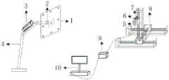
图1为本发明的装置结构示意图;Fig. 1 is the device structure schematic diagram of the present invention;
图2为实施例中合作光标靶的结构示意图;Fig. 2 is the structural representation of cooperation cursor target in the embodiment;
图3为本发明的方法流程示意图;Fig. 3 is a schematic flow chart of the method of the present invention;
图4为实施例中LED光源的亮度与闪烁顺序联合调制脉冲信号示意图;Fig. 4 is a schematic diagram of the joint modulation pulse signal of the brightness and the blinking sequence of the LED light source in the embodiment;
图中标记说明:1、合作光标靶,2、姿态角度传感器,3、调光控制器,4、机械臂,5、PSD探测器,6、水平尺,7、激光测距仪,8、三维移动平台,9、数据采集单元,10、计算机,101、面板,102、LED光源,103、光学透镜。Marking description in the figure: 1. Cooperation cursor target, 2. Attitude angle sensor, 3. Dimming controller, 4. Robotic arm, 5. PSD detector, 6. Level ruler, 7. Laser rangefinder, 8. Three-dimensional Mobile platform, 9, data acquisition unit, 10, computer, 101, panel, 102, LED light source, 103, optical lens.
具体实施方式Detailed ways
下面结合附图和具体实施例对本发明进行详细说明。The present invention will be described in detail below in conjunction with the accompanying drawings and specific embodiments.
实施例Example
一种合作目标空间位姿检测装置,包括携带有特征光源的合作光标靶1、调光控制器3、可调节移动位置的PSD探测器5、数据采集单元9以及计算机10,其中,合作光标靶1连接有光标靶姿态控制系统,PSD探测器5、数据采集单元9和计算机10依次连接,光标靶姿态控制系统包括机械臂4和姿态角度传感器2,合作光标靶1安装在机械臂4的末端,姿态角度传感器2安装在合作光标靶1的后方,姿态角度传感器2用于实时探测合作光标靶1的姿态角度信息,配合机械臂4用于实现合作光标靶1俯仰角、偏航角以及翻滚角的姿态调节;A cooperative target space posture detection device, including a
调光控制器3用于对合作光标靶1上特征光源的亮度以及闪烁顺序进行控制,本实施例中,调光控制器3包括主控单元,主控单元连接有对应于各LED光源的多路LED驱动单元,主控单元用于输出多个独立的PWM脉冲信号给多路LED驱动单元,以独立控制各LED光源的亮度,调光控制器3还包括用于控制各LED光源闪烁顺序的嵌入式MCU;The dimming
PSD探测器5用于探测合作光标靶1上特征光源的位置信息,并将探测的数据信息通过数据采集单元9传输给计算机10,PSD探测器5安装在三维移动平台8上,三维移动平台8用于实现PSD探测器5的上下左右空间位置移动,三维移动平台8上安装有水平尺6和激光测距仪7,激光测距仪7用于测量PSD探测器5与合作光标靶1之间的距离,在实际应用中,三维移动平台8上设置四个驱动电机,其中两个驱动电机用于同步驱动两个平行滑轨上滑块在水平x方向的移动,从而实现PSD探测器5在水平左右方向的移动,另一个驱动电机则用于实现PSD探测器5在垂直上下y方向的移动,还有一个驱动电机用于实现PSD探测器5在前后z方向的移动;The
计算机10根据合作光标靶1上特征光源的位置信息,完成合作目标空间位姿解算,得到合作光标靶1对应的空间位姿数据。The
如图2所示,合作光标靶1包括面板101,面板上设置有呈矩阵排列的多个LED光源102,本实施例采用大功率LED光源,LED光源102前方安装有光学透镜103,用于发散角优化,形成能量均匀集中的高亮光斑,从而增加探测光源和环境背景光的对比度、提升空间光点探测解算系统的信噪比。As shown in Figure 2, the
将上述装置应用于实际,以实现一种合作目标空间位姿检测方法,如图3所示,包括以下步骤:Apply the above-mentioned device to practice to realize a method for detecting the space pose of a cooperative target, as shown in Figure 3, including the following steps:
S1、光标靶姿态控制系统对合作光标靶俯仰角、偏航角以及翻滚角进行姿态调节,同时调光控制器控制合作光标靶上特征光源的亮度及闪烁顺序,具体是基于PWM脉冲信号对各特征光源进行亮度的独立调节,并通过嵌入式MCU对各特征光源的闪烁顺序进行控制;S1. The cursor target attitude control system adjusts the attitude of the cooperation cursor target pitch angle, yaw angle and roll angle. At the same time, the dimming controller controls the brightness and flashing sequence of the characteristic light sources on the cooperation cursor target. The brightness of the characteristic light sources is adjusted independently, and the flashing sequence of each characteristic light source is controlled by the embedded MCU;
S2、PSD探测器实时探测合作光标靶在不同姿态下各特征光源的位置信息,并将探测的位置信息通过数据采集系统传输给计算机;S2. The PSD detector detects the position information of each characteristic light source of the cooperative cursor target in different attitudes in real time, and transmits the detected position information to the computer through the data acquisition system;
S3、计算机对接收的数据信息依次进行采样均值滤波、环境背景光补偿、PSD位置坐标计算、坐标的非线性修正、空间光点的位置解算,得到合作光标靶对应的空间位姿数据。S3. The computer sequentially performs sampling average filtering, ambient background light compensation, PSD position coordinate calculation, nonlinear correction of coordinates, and spatial light point position calculation on the received data information to obtain the spatial pose data corresponding to the cooperative cursor target.
本实施例应用上述技术方案,首先构建整体装置,包括:携带特征光点的合作光标靶,采用大功率LED作为特征光源;In this embodiment, the above-mentioned technical solution is applied, and the overall device is first constructed, including: a cooperative cursor target carrying characteristic light spots, using high-power LEDs as characteristic light sources;
光标靶姿态控制系统,将合作光标靶安装于机械臂上以便实现俯仰角、偏航角和翻滚角的姿态调节,将合作光标靶安装于可自由调节角度的机械臂上,能够实现光标靶的俯仰、偏航和翻滚角度的控制,便于实现空间位姿的探测,姿态角度传感器安装于光标靶背面用以探测光标靶运转的角度大小;Cursor target attitude control system, the cooperative cursor target is installed on the mechanical arm to realize the attitude adjustment of pitch angle, yaw angle and roll angle, and the cooperative cursor target is installed on the mechanical arm which can adjust the angle freely, so that the cursor target can be adjusted freely. The control of pitch, yaw and roll angle is convenient to realize the detection of space posture. The attitude angle sensor is installed on the back of the cursor target to detect the angle of rotation of the cursor target;
调光控制器,采用PWM恒流驱动方式对特征光源的亮度进行调制、通过嵌入式MCU控制系统对光源的闪烁顺序进行控制;The dimming controller adopts the PWM constant current driving method to modulate the brightness of the characteristic light source, and controls the flashing sequence of the light source through the embedded MCU control system;
PSD传感探测相机,用于探测空间光点的位置信息,本实施例采用双PSD传感探测相机,将双PSD传感探测相机安装在三维可移动平台上,三维可移动平台上安装水平尺以保证双PSD传感探测相机的水平位置,还在其上方安装了激光测距仪,用于测量PSD相机至标靶的距离,双PSD传感探测相机将光信号转化为电流信号,在各自光敏面成像的二维像坐标以及通过两个传感器的相对位置关系,解算出空间光点的三维位置坐标,通过前置放大电路实现光电流至电压的转换,将电压放大实现A/D转换,再通过数据采集单元传输给计算机,以对对A/D数据的处理,包括采样均值滤波、环境背景光补偿、PSD位置坐标计算、坐标的非线性修正、空间光点的位置解算等,以完成姿态分析;The PSD sensing detection camera is used to detect the position information of the light spot in space. The present embodiment adopts dual PSD sensing detection cameras, and the dual PSD sensing detection cameras are installed on the three-dimensional movable platform, and a horizontal ruler is installed on the three-dimensional movable platform. In order to ensure the horizontal position of the dual PSD sensor detection camera, a laser rangefinder is installed above it to measure the distance from the PSD camera to the target. The two-dimensional image coordinates of the photosensitive surface imaging and the relative position relationship of the two sensors are used to solve the three-dimensional position coordinates of the light spot in space, and the conversion from photocurrent to voltage is realized through the preamplifier circuit, and the voltage is amplified to realize A/D conversion. It is then transmitted to the computer through the data acquisition unit to process the A/D data, including sampling average filtering, ambient background light compensation, PSD position coordinate calculation, nonlinear correction of coordinates, position calculation of spatial light spots, etc. Complete posture analysis;
三维移动平台,用于固定和调节PSD探测器的位置;Three-dimensional mobile platform for fixing and adjusting the position of the PSD detector;
数据采集单元,对PSD采集的数据进行处理;The data acquisition unit processes the data collected by the PSD;
本实施例中,光标靶面板采用正方形,9个LED光源在标靶上按照3×3的行列排列方式均匀排布,由于LED发散角比较大,在每个LED光源前置光学透镜,形成能量均匀集中的高亮光斑,增加探测光源和环境背景光的对比度,提升空间光点探测解算系统的信噪比。LED驱动方式采用恒流驱动方式,工作电流不受LED两端电压变化的影响,而且没有额外功耗的浪费,保证发光功率的稳定。采用PT4115降压恒流LED驱动IC,通过控制内部连接功率开关的DIM管脚的电压实现调光,PWM调光通过在DIM脚输入10HZ至20kHZ以上的方波实现输出电流从0%至100%的变化,LED的亮度由PWM信号的占空比和接入DIM管脚的方波的高电平Vpwm共同决定,合作光标靶需要实现至少九路LED控制,每一路LED可实现独立的开关与调光,由此构建多路PWM调光控制系统,以STM32微控制单元作为主控单元,同时控制三组共九路LED驱动电路,并设置按键输入组、LED指示灯输出组和OLED显示屏,以此输出九路独立的PWM脉冲,通过PT4115的DIM管脚对输出电流进行控制,并且OLED与按键组合的多级菜单模式设计,便于对调整参数和模式选择。通过MCU实现特征光点的闪烁时序控制,同时利用PWM对每个LED的亮度进行独立调节。如图4所示,以三通道为例,T为一路LED的有效调光时间,t是PWM信号的一个基本脉冲宽度,D为占空比,能够决定时间内的发光强度,调制过程中,三路LED依次发光T时间,后接一个T时间的无动作周期作为调制结束的标志,系统总时间为4×T,实现光点闪烁亮度和顺序的联合调制,再根据PSD探测的位置和光强特性进行后续调制。有效时间内的发光强度由每一路的占空比决定,完整调制过程为LED依次发光T时间,再衔接一个时间T的无动作周期,作为调制结束的标志,具体的,在进行一组控制三路LED时,对于时序控制,如图4所示,先是LED1亮起;接着LED2亮起,同时LED1灯灭;然后LED3亮起,同时LED2灯灭;In this embodiment, the cursor target panel adopts a square shape, and 9 LED light sources are evenly arranged on the target in a row and column arrangement of 3×3. Since the LED divergence angle is relatively large, an optical lens is placed in front of each LED light source to form energy The uniform and concentrated highlight spot increases the contrast between the detection light source and the ambient background light, and improves the signal-to-noise ratio of the spatial light point detection and calculation system. The LED driving method adopts the constant current driving method, the working current is not affected by the voltage change at both ends of the LED, and there is no waste of extra power consumption, which ensures the stability of the luminous power. Using PT4115 step-down constant current LED driver IC, dimming is achieved by controlling the voltage of the DIM pin connected to the internal power switch, and PWM dimming is achieved by inputting a square wave above 10HZ to 20kHZ at the DIM pin to achieve output current from 0% to 100%. The brightness of the LED is determined by the duty cycle of the PWM signal and the high-level Vpwm of the square wave connected to the DIM pin. The cooperative cursor target needs to realize at least nine LED controls, and each LED can be independently switched. and dimming, thus constructing a multi-channel PWM dimming control system, using the STM32 micro-control unit as the main control unit, simultaneously controlling three groups of nine-channel LED drive circuits, and setting key input groups, LED indicator output groups and OLED display screen, so as to output nine independent PWM pulses, and control the output current through the DIM pin of PT4115, and the multi-level menu mode design of OLED and button combination is convenient for adjusting parameters and mode selection. The flickering sequence control of the characteristic light spots is realized by the MCU, and the brightness of each LED is independently adjusted by PWM. As shown in Figure 4, taking three channels as an example, T is the effective dimming time of one LED, t is a basic pulse width of the PWM signal, and D is the duty cycle, which can determine the luminous intensity within the time. During the modulation process, The three-way LEDs emit light sequentially for T time, followed by a non-action period of T time as the sign of the end of modulation. Strong features for subsequent modulation. The luminous intensity within the effective time is determined by the duty cycle of each channel. The complete modulation process is that the LEDs emit light sequentially for T time, and then connect a non-action period of time T as a sign of the end of modulation. Specifically, a group of control three For timing control, as shown in Figure 4, first LED1 lights up; then LED2 lights up, and LED1 lights off; then LED3 lights up, and LED2 lights off at the same time;
同时PWM脉冲可对每个LED的亮度进行独立调节:首先T为一路LED的有效调光时间,其中t是PWM信号的一个基本脉冲宽度,D为占空比,时间内的发光强度由每一路的占空比决定;At the same time, the PWM pulse can independently adjust the brightness of each LED: first, T is the effective dimming time of one LED, where t is a basic pulse width of the PWM signal, D is the duty cycle, and the luminous intensity within the time is determined by each LED. The duty cycle decision;
由此在时序顺序下,不同的占空比即代表不同的亮度调制,在时序顺序条件下,可以同时对每一路的PWM脉冲进行独立控制,随时调节每一路的亮度大小。Therefore, under the sequential order, different duty ratios represent different brightness modulations. Under the condition of sequential order, the PWM pulses of each channel can be controlled independently at the same time, and the brightness of each channel can be adjusted at any time.
Claims (5)
Priority Applications (1)
| Application Number | Priority Date | Filing Date | Title |
|---|---|---|---|
| CN202110719464.8ACN113390343B (en) | 2021-06-28 | 2021-06-28 | A space pose detection device and method for a cooperative target |
Applications Claiming Priority (1)
| Application Number | Priority Date | Filing Date | Title |
|---|---|---|---|
| CN202110719464.8ACN113390343B (en) | 2021-06-28 | 2021-06-28 | A space pose detection device and method for a cooperative target |
Publications (2)
| Publication Number | Publication Date |
|---|---|
| CN113390343A CN113390343A (en) | 2021-09-14 |
| CN113390343Btrue CN113390343B (en) | 2023-05-30 |
Family
ID=77624190
Family Applications (1)
| Application Number | Title | Priority Date | Filing Date |
|---|---|---|---|
| CN202110719464.8AActiveCN113390343B (en) | 2021-06-28 | 2021-06-28 | A space pose detection device and method for a cooperative target |
Country Status (1)
| Country | Link |
|---|---|
| CN (1) | CN113390343B (en) |
Families Citing this family (1)
| Publication number | Priority date | Publication date | Assignee | Title |
|---|---|---|---|---|
| US20250198744A1 (en)* | 2023-12-15 | 2025-06-19 | Mitutoyo Corporation | Metrology system with high speed position and orientation tracking mode |
Citations (1)
| Publication number | Priority date | Publication date | Assignee | Title |
|---|---|---|---|---|
| CN111953912A (en)* | 2020-07-27 | 2020-11-17 | 天津大学 | A method and device for detecting the spatial position of a high-speed moving light spot |
Family Cites Families (11)
| Publication number | Priority date | Publication date | Assignee | Title |
|---|---|---|---|---|
| US6285831B1 (en)* | 1997-09-09 | 2001-09-04 | Minolta Co., Ltd. | Optical apparatus with a posture detection device |
| DE10130423B4 (en)* | 2001-06-23 | 2004-02-05 | Forschungszentrum Karlsruhe Gmbh | Optical 3D position measuring system for the simultaneous detection of six degrees of freedom |
| US7961909B2 (en)* | 2006-03-08 | 2011-06-14 | Electronic Scripting Products, Inc. | Computer interface employing a manipulated object with absolute pose detection component and a display |
| CN101968341A (en)* | 2010-08-31 | 2011-02-09 | 南京理工大学 | Industrial robot zero-position self-calibration method and device |
| CN102548156B (en)* | 2012-02-24 | 2014-08-13 | 南京航空航天大学 | Self-adaptive brightness control system and method for multichannel infrared LED (Light-Emitting Diode) target spot |
| CN103063201A (en)* | 2012-12-19 | 2013-04-24 | 江苏安德信超导加速器科技有限公司 | Three-dimensional pose detection device and measurement method |
| CN108051005A (en)* | 2017-11-30 | 2018-05-18 | 天津大学 | The single PSD detection methods of Target space position and posture |
| EP3614173A1 (en)* | 2018-08-20 | 2020-02-26 | Leica Geosystems AG | Surveying device with automatic training of locked object or person for camera based target tracking |
| CN111750773B (en)* | 2019-03-29 | 2022-02-18 | 南京理工大学 | Method for measuring response of different light spot points on position sensitive detector |
| CN212578650U (en)* | 2020-06-30 | 2021-02-23 | 上海微创医疗器械(集团)有限公司 | A device for detecting the pose error of a robotic arm |
| CN112556579A (en)* | 2020-12-25 | 2021-03-26 | 深圳市中图仪器股份有限公司 | Six-degree-of-freedom space coordinate position and attitude measuring device |
- 2021
- 2021-06-28CNCN202110719464.8Apatent/CN113390343B/enactiveActive
Patent Citations (1)
| Publication number | Priority date | Publication date | Assignee | Title |
|---|---|---|---|---|
| CN111953912A (en)* | 2020-07-27 | 2020-11-17 | 天津大学 | A method and device for detecting the spatial position of a high-speed moving light spot |
Non-Patent Citations (1)
| Title |
|---|
| 基于单PSD的目标空间位姿测量方法;黄战华;张亚男;方石;蔡怀宇;;光子学报(09);全文* |
Also Published As
| Publication number | Publication date |
|---|---|
| CN113390343A (en) | 2021-09-14 |
Similar Documents
| Publication | Publication Date | Title |
|---|---|---|
| CN104036226B (en) | A method for acquiring target information and electronic equipment | |
| CN104457569B (en) | A kind of large-scale composite board geometric parameter vision measuring method | |
| WO2019062423A1 (en) | Automatic stage lighting tracking system and control method therefor | |
| CN103245951B (en) | Coupling distance and intensity imaging for estimation | |
| CN107037880A (en) | Space orientation attitude determination system and its method based on virtual reality technology | |
| CN103885449B (en) | Control method of intelligent visual tracking wheeled robot based on multi-sensor collaborative processing | |
| US20170316267A1 (en) | Dynamic adjustment of imaging parameters | |
| WO2006095519A1 (en) | Perspective distortion inspecting equipment and method of translucent panel | |
| CN108663032B (en) | Robot-based working face hydraulic support attitude and straightness detection device and method | |
| CN113390343B (en) | A space pose detection device and method for a cooperative target | |
| CN108871307B (en) | Y waveguide chip direct coupling device based on image recognition and optical power feedback | |
| CN101916112A (en) | Positioning and control system and method for smart car model in indoor scene | |
| CN111721265A (en) | A three-dimensional measuring device for indoor ground inclination | |
| Hadviger et al. | Stereo visual localization dataset featuring event cameras | |
| JP2012103076A (en) | Apparatus and method for taking three-dimensional measurements | |
| CN110030988B (en) | Multi-beacon high-speed synchronous identification method for high-dynamic pose measurement | |
| CN107181919A (en) | Optical detection apparatus | |
| CN109799632B (en) | Precise laminating device and method for liquid crystal display screen and touch panel based on laser sensor | |
| CN104527641A (en) | Machine-vision-based parking vehicle speed detection system | |
| CN212254080U (en) | A three-dimensional measuring device for indoor ground inclination | |
| CN109859235A (en) | A kind of night mobile car light tracing detection system, method and apparatus | |
| CN109375170B (en) | Robot visible light real-time positioning device and positioning method thereof | |
| JP5803534B2 (en) | Optical communication apparatus and program | |
| CN213199916U (en) | Survey car | |
| CN108230865A (en) | Automated teaching apparatus based on spin control system |
Legal Events
| Date | Code | Title | Description |
|---|---|---|---|
| PB01 | Publication | ||
| PB01 | Publication | ||
| SE01 | Entry into force of request for substantive examination | ||
| SE01 | Entry into force of request for substantive examination | ||
| GR01 | Patent grant | ||
| GR01 | Patent grant |