CN113382760B - Device for dispensing a fluid product in synchronism with inhalation - Google Patents
Device for dispensing a fluid product in synchronism with inhalationDownload PDFInfo
- Publication number
- CN113382760B CN113382760BCN202080012422.4ACN202080012422ACN113382760BCN 113382760 BCN113382760 BCN 113382760BCN 202080012422 ACN202080012422 ACN 202080012422ACN 113382760 BCN113382760 BCN 113382760B
- Authority
- CN
- China
- Prior art keywords
- locking
- inhalation
- fluid product
- dispensing
- actuator
- Prior art date
- Legal status (The legal status is an assumption and is not a legal conclusion. Google has not performed a legal analysis and makes no representation as to the accuracy of the status listed.)
- Active
Links
- 239000012530fluidSubstances0.000titleclaimsdescription80
- 230000033001locomotionEffects0.000claimsdescription25
- 239000012528membraneSubstances0.000claimsdescription13
- 230000009471actionEffects0.000claimsdescription7
- 230000000694effectsEffects0.000claimsdescription4
- 239000003380propellantSubstances0.000claimsdescription4
- 230000000007visual effectEffects0.000claimsdescription3
- 230000011664signalingEffects0.000description6
- 238000004519manufacturing processMethods0.000description4
- 238000003860storageMethods0.000description4
- 239000000443aerosolSubstances0.000description3
- 229940079593drugDrugs0.000description3
- 239000003814drugSubstances0.000description3
- 230000014509gene expressionEffects0.000description3
- 230000001360synchronised effectEffects0.000description3
- YBYIRNPNPLQARY-UHFFFAOYSA-N1H-indeneChemical compoundC1=CC=C2CC=CC2=C1YBYIRNPNPLQARY-UHFFFAOYSA-N0.000description2
- 230000008901benefitEffects0.000description2
- 238000002788crimpingMethods0.000description2
- 238000013016dampingMethods0.000description2
- 238000006073displacement reactionMethods0.000description2
- 238000003825pressingMethods0.000description2
- VOVIALXJUBGFJZ-KWVAZRHASA-NBudesonideChemical compoundC1CC2=CC(=O)C=C[C@]2(C)[C@@H]2[C@@H]1[C@@H]1C[C@H]3OC(CCC)O[C@@]3(C(=O)CO)[C@@]1(C)C[C@@H]2OVOVIALXJUBGFJZ-KWVAZRHASA-N0.000description1
- LERNTVKEWCAPOY-VOGVJGKGSA-NC[N+]1(C)[C@H]2C[C@H](C[C@@H]1[C@H]1O[C@@H]21)OC(=O)C(O)(c1cccs1)c1cccs1Chemical compoundC[N+]1(C)[C@H]2C[C@H](C[C@@H]1[C@H]1O[C@@H]21)OC(=O)C(O)(c1cccs1)c1cccs1LERNTVKEWCAPOY-VOGVJGKGSA-N0.000description1
- 208000006545Chronic Obstructive Pulmonary DiseaseDiseases0.000description1
- VPNYRYCIDCJBOM-UHFFFAOYSA-MGlycopyrronium bromideChemical compound[Br-].C1[N+](C)(C)CCC1OC(=O)C(O)(C=1C=CC=CC=1)C1CCCC1VPNYRYCIDCJBOM-UHFFFAOYSA-M0.000description1
- GIIZNNXWQWCKIB-UHFFFAOYSA-NSereventChemical compoundC1=C(O)C(CO)=CC(C(O)CNCCCCCCOCCCCC=2C=CC=CC=2)=C1GIIZNNXWQWCKIB-UHFFFAOYSA-N0.000description1
- ASMXXROZKSBQIH-VITNCHFBSA-NaclidiniumChemical compoundC([C@@H](C(CC1)CC2)OC(=O)C(O)(C=3SC=CC=3)C=3SC=CC=3)[N+]21CCCOC1=CC=CC=C1ASMXXROZKSBQIH-VITNCHFBSA-N0.000description1
- 229960005012aclidinium bromideDrugs0.000description1
- 230000004913activationEffects0.000description1
- 239000004480active ingredientSubstances0.000description1
- NDAUXUAQIAJITI-UHFFFAOYSA-NalbuterolChemical compoundCC(C)(C)NCC(O)C1=CC=C(O)C(CO)=C1NDAUXUAQIAJITI-UHFFFAOYSA-N0.000description1
- 230000003321amplificationEffects0.000description1
- 208000006673asthmaDiseases0.000description1
- 230000005540biological transmissionEffects0.000description1
- 229960004436budesonideDrugs0.000description1
- 230000008859changeEffects0.000description1
- 238000004891communicationMethods0.000description1
- 239000000470constituentSubstances0.000description1
- 230000001934delayEffects0.000description1
- FVTWTVQXNAJTQP-UHFFFAOYSA-Ndiphenyl-[1-(2-phenylmethoxyethyl)-1-azoniabicyclo[2.2.2]octan-4-yl]methanolChemical compoundC=1C=CC=CC=1C(C12CC[N+](CCOCC=3C=CC=CC=3)(CC1)CC2)(O)C1=CC=CC=C1FVTWTVQXNAJTQP-UHFFFAOYSA-N0.000description1
- 238000009826distributionMethods0.000description1
- 229920001971elastomerPolymers0.000description1
- 239000000806elastomerSubstances0.000description1
- 230000007613environmental effectEffects0.000description1
- 229960002714fluticasoneDrugs0.000description1
- MGNNYOODZCAHBA-GQKYHHCASA-NfluticasoneChemical compoundC1([C@@H](F)C2)=CC(=O)C=C[C@]1(C)[C@]1(F)[C@@H]2[C@@H]2C[C@@H](C)[C@@](C(=O)SCF)(O)[C@@]2(C)C[C@@H]1OMGNNYOODZCAHBA-GQKYHHCASA-N0.000description1
- 229960002848formoterolDrugs0.000description1
- BPZSYCZIITTYBL-UHFFFAOYSA-NformoterolChemical compoundC1=CC(OC)=CC=C1CC(C)NCC(O)C1=CC=C(O)C(NC=O)=C1BPZSYCZIITTYBL-UHFFFAOYSA-N0.000description1
- 229940015042glycopyrrolateDrugs0.000description1
- 238000010438heat treatmentMethods0.000description1
- 238000003780insertionMethods0.000description1
- 230000037431insertionEffects0.000description1
- 239000007788liquidSubstances0.000description1
- 210000004072lungAnatomy0.000description1
- 230000007257malfunctionEffects0.000description1
- 238000000034methodMethods0.000description1
- 238000012986modificationMethods0.000description1
- 230000004048modificationEffects0.000description1
- 238000003199nucleic acid amplification methodMethods0.000description1
- 229960004286olodaterolDrugs0.000description1
- COUYJEVMBVSIHV-SFHVURJKSA-NolodaterolChemical compoundC1=CC(OC)=CC=C1CC(C)(C)NC[C@H](O)C1=CC(O)=CC2=C1OCC(=O)N2COUYJEVMBVSIHV-SFHVURJKSA-N0.000description1
- 238000007649pad printingMethods0.000description1
- 230000002093peripheral effectEffects0.000description1
- 238000002360preparation methodMethods0.000description1
- 230000002265preventionEffects0.000description1
- 230000001681protective effectEffects0.000description1
- 230000009467reductionEffects0.000description1
- 230000000241respiratory effectEffects0.000description1
- 229960002052salbutamolDrugs0.000description1
- 229960004017salmeterolDrugs0.000description1
- 230000000087stabilizing effectEffects0.000description1
- 238000005728strengtheningMethods0.000description1
- 229960000257tiotropium bromideDrugs0.000description1
- 238000013519translationMethods0.000description1
- 230000001960triggered effectEffects0.000description1
- 229960004258umeclidiniumDrugs0.000description1
- 229960004026vilanterolDrugs0.000description1
- DAFYYTQWSAWIGS-DEOSSOPVSA-NvilanterolChemical compoundC1=C(O)C(CO)=CC([C@@H](O)CNCCCCCCOCCOCC=2C(=CC=CC=2Cl)Cl)=C1DAFYYTQWSAWIGS-DEOSSOPVSA-N0.000description1
Images


Classifications
- A—HUMAN NECESSITIES
- A61—MEDICAL OR VETERINARY SCIENCE; HYGIENE
- A61M—DEVICES FOR INTRODUCING MEDIA INTO, OR ONTO, THE BODY; DEVICES FOR TRANSDUCING BODY MEDIA OR FOR TAKING MEDIA FROM THE BODY; DEVICES FOR PRODUCING OR ENDING SLEEP OR STUPOR
- A61M15/00—Inhalators
- A61M15/0091—Inhalators mechanically breath-triggered
- A61M15/0095—Preventing manual activation in absence of inhalation
- A—HUMAN NECESSITIES
- A61—MEDICAL OR VETERINARY SCIENCE; HYGIENE
- A61M—DEVICES FOR INTRODUCING MEDIA INTO, OR ONTO, THE BODY; DEVICES FOR TRANSDUCING BODY MEDIA OR FOR TAKING MEDIA FROM THE BODY; DEVICES FOR PRODUCING OR ENDING SLEEP OR STUPOR
- A61M15/00—Inhalators
- A61M15/0001—Details of inhalators; Constructional features thereof
- A61M15/002—Details of inhalators; Constructional features thereof with air flow regulating means
- A—HUMAN NECESSITIES
- A61—MEDICAL OR VETERINARY SCIENCE; HYGIENE
- A61M—DEVICES FOR INTRODUCING MEDIA INTO, OR ONTO, THE BODY; DEVICES FOR TRANSDUCING BODY MEDIA OR FOR TAKING MEDIA FROM THE BODY; DEVICES FOR PRODUCING OR ENDING SLEEP OR STUPOR
- A61M15/00—Inhalators
- A61M15/0001—Details of inhalators; Constructional features thereof
- A61M15/0021—Mouthpieces therefor
- A61M15/0025—Mouthpieces therefor with caps
- A61M15/0026—Hinged caps
- A—HUMAN NECESSITIES
- A61—MEDICAL OR VETERINARY SCIENCE; HYGIENE
- A61M—DEVICES FOR INTRODUCING MEDIA INTO, OR ONTO, THE BODY; DEVICES FOR TRANSDUCING BODY MEDIA OR FOR TAKING MEDIA FROM THE BODY; DEVICES FOR PRODUCING OR ENDING SLEEP OR STUPOR
- A61M15/00—Inhalators
- A61M15/0065—Inhalators with dosage or measuring devices
- A61M15/0068—Indicating or counting the number of dispensed doses or of remaining doses
- A61M15/008—Electronic counters
- A—HUMAN NECESSITIES
- A61—MEDICAL OR VETERINARY SCIENCE; HYGIENE
- A61M—DEVICES FOR INTRODUCING MEDIA INTO, OR ONTO, THE BODY; DEVICES FOR TRANSDUCING BODY MEDIA OR FOR TAKING MEDIA FROM THE BODY; DEVICES FOR PRODUCING OR ENDING SLEEP OR STUPOR
- A61M15/00—Inhalators
- A61M15/009—Inhalators using medicine packages with incorporated spraying means, e.g. aerosol cans
- A—HUMAN NECESSITIES
- A61—MEDICAL OR VETERINARY SCIENCE; HYGIENE
- A61P—SPECIFIC THERAPEUTIC ACTIVITY OF CHEMICAL COMPOUNDS OR MEDICINAL PREPARATIONS
- A61P11/00—Drugs for disorders of the respiratory system
- A61P11/06—Antiasthmatics
- A—HUMAN NECESSITIES
- A61—MEDICAL OR VETERINARY SCIENCE; HYGIENE
- A61P—SPECIFIC THERAPEUTIC ACTIVITY OF CHEMICAL COMPOUNDS OR MEDICINAL PREPARATIONS
- A61P11/00—Drugs for disorders of the respiratory system
- A61P11/08—Bronchodilators
- B—PERFORMING OPERATIONS; TRANSPORTING
- B65—CONVEYING; PACKING; STORING; HANDLING THIN OR FILAMENTARY MATERIAL
- B65D—CONTAINERS FOR STORAGE OR TRANSPORT OF ARTICLES OR MATERIALS, e.g. BAGS, BARRELS, BOTTLES, BOXES, CANS, CARTONS, CRATES, DRUMS, JARS, TANKS, HOPPERS, FORWARDING CONTAINERS; ACCESSORIES, CLOSURES, OR FITTINGS THEREFOR; PACKAGING ELEMENTS; PACKAGES
- B65D83/00—Containers or packages with special means for dispensing contents
- B65D83/14—Containers for dispensing liquid or semi-liquid contents by internal gaseous pressure, i.e. aerosol containers comprising propellant
- B65D83/16—Actuating means
- B65D83/22—Actuating means with means to disable actuation
- B65D83/222—Actuator locking means that are automatically engaged after each actuation
- B—PERFORMING OPERATIONS; TRANSPORTING
- B65—CONVEYING; PACKING; STORING; HANDLING THIN OR FILAMENTARY MATERIAL
- B65D—CONTAINERS FOR STORAGE OR TRANSPORT OF ARTICLES OR MATERIALS, e.g. BAGS, BARRELS, BOTTLES, BOXES, CANS, CARTONS, CRATES, DRUMS, JARS, TANKS, HOPPERS, FORWARDING CONTAINERS; ACCESSORIES, CLOSURES, OR FITTINGS THEREFOR; PACKAGING ELEMENTS; PACKAGES
- B65D83/00—Containers or packages with special means for dispensing contents
- B65D83/14—Containers for dispensing liquid or semi-liquid contents by internal gaseous pressure, i.e. aerosol containers comprising propellant
- B65D83/16—Actuating means
- B65D83/26—Actuating means operating automatically, e.g. periodically
- B65D83/267—Actuating means operating automatically, e.g. periodically by a separate device actuated by repeated, e.g. human, input, e.g. by a moving wing of a door or window, a ringing doorbell, a flushing toilet
- A—HUMAN NECESSITIES
- A61—MEDICAL OR VETERINARY SCIENCE; HYGIENE
- A61K—PREPARATIONS FOR MEDICAL, DENTAL OR TOILETRY PURPOSES
- A61K31/00—Medicinal preparations containing organic active ingredients
- A61K31/13—Amines
- A61K31/135—Amines having aromatic rings, e.g. ketamine, nortriptyline
- A61K31/137—Arylalkylamines, e.g. amphetamine, epinephrine, salbutamol, ephedrine or methadone
- A—HUMAN NECESSITIES
- A61—MEDICAL OR VETERINARY SCIENCE; HYGIENE
- A61K—PREPARATIONS FOR MEDICAL, DENTAL OR TOILETRY PURPOSES
- A61K31/00—Medicinal preparations containing organic active ingredients
- A61K31/16—Amides, e.g. hydroxamic acids
- A61K31/165—Amides, e.g. hydroxamic acids having aromatic rings, e.g. colchicine, atenolol, progabide
- A61K31/167—Amides, e.g. hydroxamic acids having aromatic rings, e.g. colchicine, atenolol, progabide having the nitrogen of a carboxamide group directly attached to the aromatic ring, e.g. lidocaine, paracetamol
- A—HUMAN NECESSITIES
- A61—MEDICAL OR VETERINARY SCIENCE; HYGIENE
- A61K—PREPARATIONS FOR MEDICAL, DENTAL OR TOILETRY PURPOSES
- A61K31/00—Medicinal preparations containing organic active ingredients
- A61K31/33—Heterocyclic compounds
- A61K31/395—Heterocyclic compounds having nitrogen as a ring hetero atom, e.g. guanethidine or rifamycins
- A61K31/40—Heterocyclic compounds having nitrogen as a ring hetero atom, e.g. guanethidine or rifamycins having five-membered rings with one nitrogen as the only ring hetero atom, e.g. sulpiride, succinimide, tolmetin, buflomedil
- A—HUMAN NECESSITIES
- A61—MEDICAL OR VETERINARY SCIENCE; HYGIENE
- A61K—PREPARATIONS FOR MEDICAL, DENTAL OR TOILETRY PURPOSES
- A61K31/00—Medicinal preparations containing organic active ingredients
- A61K31/33—Heterocyclic compounds
- A61K31/395—Heterocyclic compounds having nitrogen as a ring hetero atom, e.g. guanethidine or rifamycins
- A61K31/435—Heterocyclic compounds having nitrogen as a ring hetero atom, e.g. guanethidine or rifamycins having six-membered rings with one nitrogen as the only ring hetero atom
- A61K31/439—Heterocyclic compounds having nitrogen as a ring hetero atom, e.g. guanethidine or rifamycins having six-membered rings with one nitrogen as the only ring hetero atom the ring forming part of a bridged ring system, e.g. quinuclidine
- A—HUMAN NECESSITIES
- A61—MEDICAL OR VETERINARY SCIENCE; HYGIENE
- A61K—PREPARATIONS FOR MEDICAL, DENTAL OR TOILETRY PURPOSES
- A61K31/00—Medicinal preparations containing organic active ingredients
- A61K31/33—Heterocyclic compounds
- A61K31/395—Heterocyclic compounds having nitrogen as a ring hetero atom, e.g. guanethidine or rifamycins
- A61K31/435—Heterocyclic compounds having nitrogen as a ring hetero atom, e.g. guanethidine or rifamycins having six-membered rings with one nitrogen as the only ring hetero atom
- A61K31/47—Quinolines; Isoquinolines
- A61K31/4704—2-Quinolinones, e.g. carbostyril
- A—HUMAN NECESSITIES
- A61—MEDICAL OR VETERINARY SCIENCE; HYGIENE
- A61K—PREPARATIONS FOR MEDICAL, DENTAL OR TOILETRY PURPOSES
- A61K31/00—Medicinal preparations containing organic active ingredients
- A61K31/56—Compounds containing cyclopenta[a]hydrophenanthrene ring systems; Derivatives thereof, e.g. steroids
- A61K31/58—Compounds containing cyclopenta[a]hydrophenanthrene ring systems; Derivatives thereof, e.g. steroids containing heterocyclic rings, e.g. danazol, stanozolol, pancuronium or digitogenin
- A—HUMAN NECESSITIES
- A61—MEDICAL OR VETERINARY SCIENCE; HYGIENE
- A61M—DEVICES FOR INTRODUCING MEDIA INTO, OR ONTO, THE BODY; DEVICES FOR TRANSDUCING BODY MEDIA OR FOR TAKING MEDIA FROM THE BODY; DEVICES FOR PRODUCING OR ENDING SLEEP OR STUPOR
- A61M15/00—Inhalators
- A61M15/0065—Inhalators with dosage or measuring devices
- A61M15/0068—Indicating or counting the number of dispensed doses or of remaining doses
- A61M15/007—Mechanical counters
- A—HUMAN NECESSITIES
- A61—MEDICAL OR VETERINARY SCIENCE; HYGIENE
- A61M—DEVICES FOR INTRODUCING MEDIA INTO, OR ONTO, THE BODY; DEVICES FOR TRANSDUCING BODY MEDIA OR FOR TAKING MEDIA FROM THE BODY; DEVICES FOR PRODUCING OR ENDING SLEEP OR STUPOR
- A61M15/00—Inhalators
- A61M15/08—Inhaling devices inserted into the nose
- A—HUMAN NECESSITIES
- A61—MEDICAL OR VETERINARY SCIENCE; HYGIENE
- A61M—DEVICES FOR INTRODUCING MEDIA INTO, OR ONTO, THE BODY; DEVICES FOR TRANSDUCING BODY MEDIA OR FOR TAKING MEDIA FROM THE BODY; DEVICES FOR PRODUCING OR ENDING SLEEP OR STUPOR
- A61M16/00—Devices for influencing the respiratory system of patients by gas treatment, e.g. ventilators; Tracheal tubes
- A61M16/0003—Accessories therefor, e.g. sensors, vibrators, negative pressure
- A61M2016/0027—Accessories therefor, e.g. sensors, vibrators, negative pressure pressure meter
- A—HUMAN NECESSITIES
- A61—MEDICAL OR VETERINARY SCIENCE; HYGIENE
- A61M—DEVICES FOR INTRODUCING MEDIA INTO, OR ONTO, THE BODY; DEVICES FOR TRANSDUCING BODY MEDIA OR FOR TAKING MEDIA FROM THE BODY; DEVICES FOR PRODUCING OR ENDING SLEEP OR STUPOR
- A61M16/00—Devices for influencing the respiratory system of patients by gas treatment, e.g. ventilators; Tracheal tubes
- A61M16/0003—Accessories therefor, e.g. sensors, vibrators, negative pressure
- A61M2016/003—Accessories therefor, e.g. sensors, vibrators, negative pressure with a flowmeter
- A61M2016/0033—Accessories therefor, e.g. sensors, vibrators, negative pressure with a flowmeter electrical
- A61M2016/0039—Accessories therefor, e.g. sensors, vibrators, negative pressure with a flowmeter electrical in the inspiratory circuit
- A—HUMAN NECESSITIES
- A61—MEDICAL OR VETERINARY SCIENCE; HYGIENE
- A61M—DEVICES FOR INTRODUCING MEDIA INTO, OR ONTO, THE BODY; DEVICES FOR TRANSDUCING BODY MEDIA OR FOR TAKING MEDIA FROM THE BODY; DEVICES FOR PRODUCING OR ENDING SLEEP OR STUPOR
- A61M2202/00—Special media to be introduced, removed or treated
- A61M2202/04—Liquids
- A61M2202/0468—Liquids non-physiological
- A—HUMAN NECESSITIES
- A61—MEDICAL OR VETERINARY SCIENCE; HYGIENE
- A61M—DEVICES FOR INTRODUCING MEDIA INTO, OR ONTO, THE BODY; DEVICES FOR TRANSDUCING BODY MEDIA OR FOR TAKING MEDIA FROM THE BODY; DEVICES FOR PRODUCING OR ENDING SLEEP OR STUPOR
- A61M2205/00—General characteristics of the apparatus
- A61M2205/02—General characteristics of the apparatus characterised by a particular materials
- A61M2205/0216—Materials providing elastic properties, e.g. for facilitating deformation and avoid breaking
- A—HUMAN NECESSITIES
- A61—MEDICAL OR VETERINARY SCIENCE; HYGIENE
- A61M—DEVICES FOR INTRODUCING MEDIA INTO, OR ONTO, THE BODY; DEVICES FOR TRANSDUCING BODY MEDIA OR FOR TAKING MEDIA FROM THE BODY; DEVICES FOR PRODUCING OR ENDING SLEEP OR STUPOR
- A61M2205/00—General characteristics of the apparatus
- A61M2205/27—General characteristics of the apparatus preventing use
- A61M2205/276—General characteristics of the apparatus preventing use preventing unwanted use
- A—HUMAN NECESSITIES
- A61—MEDICAL OR VETERINARY SCIENCE; HYGIENE
- A61M—DEVICES FOR INTRODUCING MEDIA INTO, OR ONTO, THE BODY; DEVICES FOR TRANSDUCING BODY MEDIA OR FOR TAKING MEDIA FROM THE BODY; DEVICES FOR PRODUCING OR ENDING SLEEP OR STUPOR
- A61M2205/00—General characteristics of the apparatus
- A61M2205/33—Controlling, regulating or measuring
- A61M2205/332—Force measuring means
- A—HUMAN NECESSITIES
- A61—MEDICAL OR VETERINARY SCIENCE; HYGIENE
- A61M—DEVICES FOR INTRODUCING MEDIA INTO, OR ONTO, THE BODY; DEVICES FOR TRANSDUCING BODY MEDIA OR FOR TAKING MEDIA FROM THE BODY; DEVICES FOR PRODUCING OR ENDING SLEEP OR STUPOR
- A61M2205/00—General characteristics of the apparatus
- A61M2205/33—Controlling, regulating or measuring
- A61M2205/3327—Measuring
- A—HUMAN NECESSITIES
- A61—MEDICAL OR VETERINARY SCIENCE; HYGIENE
- A61M—DEVICES FOR INTRODUCING MEDIA INTO, OR ONTO, THE BODY; DEVICES FOR TRANSDUCING BODY MEDIA OR FOR TAKING MEDIA FROM THE BODY; DEVICES FOR PRODUCING OR ENDING SLEEP OR STUPOR
- A61M2205/00—General characteristics of the apparatus
- A61M2205/33—Controlling, regulating or measuring
- A61M2205/3331—Pressure; Flow
- A61M2205/3334—Measuring or controlling the flow rate
- A—HUMAN NECESSITIES
- A61—MEDICAL OR VETERINARY SCIENCE; HYGIENE
- A61M—DEVICES FOR INTRODUCING MEDIA INTO, OR ONTO, THE BODY; DEVICES FOR TRANSDUCING BODY MEDIA OR FOR TAKING MEDIA FROM THE BODY; DEVICES FOR PRODUCING OR ENDING SLEEP OR STUPOR
- A61M2205/00—General characteristics of the apparatus
- A61M2205/35—Communication
- A61M2205/3576—Communication with non implanted data transmission devices, e.g. using external transmitter or receiver
- A61M2205/3592—Communication with non implanted data transmission devices, e.g. using external transmitter or receiver using telemetric means, e.g. radio or optical transmission
- A—HUMAN NECESSITIES
- A61—MEDICAL OR VETERINARY SCIENCE; HYGIENE
- A61M—DEVICES FOR INTRODUCING MEDIA INTO, OR ONTO, THE BODY; DEVICES FOR TRANSDUCING BODY MEDIA OR FOR TAKING MEDIA FROM THE BODY; DEVICES FOR PRODUCING OR ENDING SLEEP OR STUPOR
- A61M2205/00—General characteristics of the apparatus
- A61M2205/50—General characteristics of the apparatus with microprocessors or computers
- A61M2205/502—User interfaces, e.g. screens or keyboards
- A61M2205/505—Touch-screens; Virtual keyboard or keypads; Virtual buttons; Soft keys; Mouse touches
- A—HUMAN NECESSITIES
- A61—MEDICAL OR VETERINARY SCIENCE; HYGIENE
- A61M—DEVICES FOR INTRODUCING MEDIA INTO, OR ONTO, THE BODY; DEVICES FOR TRANSDUCING BODY MEDIA OR FOR TAKING MEDIA FROM THE BODY; DEVICES FOR PRODUCING OR ENDING SLEEP OR STUPOR
- A61M2205/00—General characteristics of the apparatus
- A61M2205/50—General characteristics of the apparatus with microprocessors or computers
- A61M2205/52—General characteristics of the apparatus with microprocessors or computers with memories providing a history of measured variating parameters of apparatus or patient
- A—HUMAN NECESSITIES
- A61—MEDICAL OR VETERINARY SCIENCE; HYGIENE
- A61M—DEVICES FOR INTRODUCING MEDIA INTO, OR ONTO, THE BODY; DEVICES FOR TRANSDUCING BODY MEDIA OR FOR TAKING MEDIA FROM THE BODY; DEVICES FOR PRODUCING OR ENDING SLEEP OR STUPOR
- A61M2205/00—General characteristics of the apparatus
- A61M2205/58—Means for facilitating use, e.g. by people with impaired vision
- A61M2205/581—Means for facilitating use, e.g. by people with impaired vision by audible feedback
- A—HUMAN NECESSITIES
- A61—MEDICAL OR VETERINARY SCIENCE; HYGIENE
- A61M—DEVICES FOR INTRODUCING MEDIA INTO, OR ONTO, THE BODY; DEVICES FOR TRANSDUCING BODY MEDIA OR FOR TAKING MEDIA FROM THE BODY; DEVICES FOR PRODUCING OR ENDING SLEEP OR STUPOR
- A61M2205/00—General characteristics of the apparatus
- A61M2205/58—Means for facilitating use, e.g. by people with impaired vision
- A61M2205/583—Means for facilitating use, e.g. by people with impaired vision by visual feedback
- A61M2205/584—Means for facilitating use, e.g. by people with impaired vision by visual feedback having a color code
- A—HUMAN NECESSITIES
- A61—MEDICAL OR VETERINARY SCIENCE; HYGIENE
- A61M—DEVICES FOR INTRODUCING MEDIA INTO, OR ONTO, THE BODY; DEVICES FOR TRANSDUCING BODY MEDIA OR FOR TAKING MEDIA FROM THE BODY; DEVICES FOR PRODUCING OR ENDING SLEEP OR STUPOR
- A61M2205/00—General characteristics of the apparatus
- A61M2205/58—Means for facilitating use, e.g. by people with impaired vision
- A61M2205/586—Ergonomic details therefor, e.g. specific ergonomics for left or right-handed users
- A—HUMAN NECESSITIES
- A61—MEDICAL OR VETERINARY SCIENCE; HYGIENE
- A61M—DEVICES FOR INTRODUCING MEDIA INTO, OR ONTO, THE BODY; DEVICES FOR TRANSDUCING BODY MEDIA OR FOR TAKING MEDIA FROM THE BODY; DEVICES FOR PRODUCING OR ENDING SLEEP OR STUPOR
- A61M2205/00—General characteristics of the apparatus
- A61M2205/82—Internal energy supply devices
- A61M2205/8206—Internal energy supply devices battery-operated
- A61M2205/8212—Internal energy supply devices battery-operated with means or measures taken for minimising energy consumption
- A—HUMAN NECESSITIES
- A61—MEDICAL OR VETERINARY SCIENCE; HYGIENE
- A61M—DEVICES FOR INTRODUCING MEDIA INTO, OR ONTO, THE BODY; DEVICES FOR TRANSDUCING BODY MEDIA OR FOR TAKING MEDIA FROM THE BODY; DEVICES FOR PRODUCING OR ENDING SLEEP OR STUPOR
- A61M2207/00—Methods of manufacture, assembly or production
- B—PERFORMING OPERATIONS; TRANSPORTING
- B65—CONVEYING; PACKING; STORING; HANDLING THIN OR FILAMENTARY MATERIAL
- B65D—CONTAINERS FOR STORAGE OR TRANSPORT OF ARTICLES OR MATERIALS, e.g. BAGS, BARRELS, BOTTLES, BOXES, CANS, CARTONS, CRATES, DRUMS, JARS, TANKS, HOPPERS, FORWARDING CONTAINERS; ACCESSORIES, CLOSURES, OR FITTINGS THEREFOR; PACKAGING ELEMENTS; PACKAGES
- B65D83/00—Containers or packages with special means for dispensing contents
- B65D83/14—Containers for dispensing liquid or semi-liquid contents by internal gaseous pressure, i.e. aerosol containers comprising propellant
- B65D83/75—Aerosol containers not provided for in groups B65D83/16 - B65D83/74
- B65D83/753—Aerosol containers not provided for in groups B65D83/16 - B65D83/74 characterised by details or accessories associated with outlets
Landscapes
- Health & Medical Sciences (AREA)
- Engineering & Computer Science (AREA)
- Life Sciences & Earth Sciences (AREA)
- Pulmonology (AREA)
- Animal Behavior & Ethology (AREA)
- Bioinformatics & Cheminformatics (AREA)
- Veterinary Medicine (AREA)
- Public Health (AREA)
- General Health & Medical Sciences (AREA)
- Heart & Thoracic Surgery (AREA)
- Biomedical Technology (AREA)
- Anesthesiology (AREA)
- Hematology (AREA)
- Chemical & Material Sciences (AREA)
- Medicinal Chemistry (AREA)
- Dispersion Chemistry (AREA)
- Mechanical Engineering (AREA)
- Chemical Kinetics & Catalysis (AREA)
- General Chemical & Material Sciences (AREA)
- Nuclear Medicine, Radiotherapy & Molecular Imaging (AREA)
- Organic Chemistry (AREA)
- Pharmacology & Pharmacy (AREA)
- Biophysics (AREA)
- Containers And Packaging Bodies Having A Special Means To Remove Contents (AREA)
- Closures For Containers (AREA)
Abstract
Translated fromChinese
Description
Translated fromChinese技术领域technical field
本发明涉及一种分配与吸入同步的流体产品分配装置,更具体地本发明涉及一种与吸入同步的气雾剂型的吸入装置。The present invention relates to a dispensing and inhalation-synchronized fluid product dispensing device, more particularly the present invention relates to an aerosol inhalation-synchronized inhalation device.
背景技术Background technique
通常由术语B.A.I.(表示“Breath Actuated Inhaler”)表示的呼吸致动吸入装置在现有技术中是众所周知的。这种类型的呼吸致动吸入装置的主要优点是产品的分配与患者吸入同步,以保证产品被适当地分配到气道中。因此,在气雾剂装置的领域中,即在借助于推进剂气体分配产品的装置领域中,已经提出了多种类型的呼吸式触发装置。然而,这些装置存在包括大量部件的缺点,即它们在制造和组装方面复杂化且成本高,这显然是不利的。还难以在致动阈值不太高的情况下对每次吸入时的可靠触发与足够坚固以防止不需要的或意外的致动的锁件之间找到适当的平衡。不幸的是,当锁件意外地解锁时,即使使用者不希望如此,装置也会自动地致动并且分配剂量。现有呼吸致动吸入装置的另一项缺点在于在使用者吸入前,甚至有时在两次致动之间的储存期间内,阀通常受应力,导致存在阀漏液和阀故障的风险。此外,在现有呼吸致动吸入装置中,在吸入后,直至使用者将呼吸致动吸入装置重置为息止位置时,例如重新闭合盖时,阀通常保持在致动位置。在此也存在阀中漏液的风险,导致使得下一剂量可能不全和/或储存器中容纳的流体产品发生损耗。Breath-actuated inhalation devices, generally denoted by the term B.A.I. (for "Breath Actuated Inhaler"), are well known in the art. The main advantage of this type of breath-actuated inhalation device is that the dispensing of the product is synchronized with the patient's inhalation to ensure that the product is properly dispensed into the airway. Therefore, in the field of aerosol devices, ie in the field of devices dispensing products by means of a propellant gas, various types of breath-triggered devices have been proposed. However, these devices have the disadvantage of comprising a large number of parts, ie they are complicated and costly to manufacture and assemble, which is clearly a disadvantage. It is also difficult to find the right balance between reliable triggering on each inhalation without the actuation threshold being too high, and a lock that is strong enough to prevent unwanted or accidental actuation. Unfortunately, when the lock is accidentally unlocked, the device automatically activates and dispenses a dose even if the user does not intend it to. Another disadvantage of existing breath-actuated inhalation devices is that the valve is often stressed before inhalation by the user, and sometimes even during storage between actuations, leading to the risk of valve leakage and valve failure. Furthermore, in existing breath-actuated inhalation devices, after inhalation, the valve typically remains in the actuated position until the user resets the breath-actuated inhalation device to the rest position, eg reclosing the cap. Here too there is a risk of leakage in the valve, with the result that the next dose may not be complete and/or the fluid contained in the reservoir is lost.
文献WO2017178764、WO2018048795、WO2017112451、US5060643、WO2004028608、US3456646、US5119806、NZ562769、US2008156321、WO2008070516、WO2010003846以及WO2013178951述及现有技术中的装置。Documents WO2017178764, WO2018048795, WO2017112451, US5060643, WO2004028608, US3456646, US5119806, NZ562769, US2008156321, WO2008070516, WO20100038316 and WO92015 devices in the prior art.
发明内容Contents of the invention
本发明旨在提供一种不再产生上述缺陷的与吸入同步分配流体产品的流体产品分配装置。The present invention aims at providing a fluid dispensing device which dispenses a fluid synchronously with inhalation which does not suffer from the aforementioned drawbacks.
本发明还旨在提供一种通过保证在每次吸入时有效致动和每次吸入时精确计量来改进运行可靠性的与吸入同步分配流体产品的流体产品分配装置。The present invention also aims to provide a fluid dispensing device that dispenses fluid synchronously with inhalation, improving operational reliability by ensuring efficient actuation on each inhalation and accurate metering on each inhalation.
本发明还旨在提供一种使意外或不需要的致动的风险最小化的与吸入同步分配流体产品的流体产品分配装置。The present invention also aims to provide a fluid dispensing device that dispenses a fluid synchronously with inhalation, minimizing the risk of accidental or unwanted actuation.
本发明还旨在提供一种在吸入之前和/或之后使阀中漏液的风险最小化的与吸入同步分配流体产品的流体产品分配装置。The present invention also aims to provide a fluid dispensing device that dispenses fluid synchronously with inhalation minimizing the risk of leakage in the valve before and/or after inhalation.
本发明还旨在提供一种不具有过高的致动阈值的与吸入同步分配流体产品的流体产品分配装置,从而使得相对较弱的人,诸如病人或老人,可以以安全可靠的方式使用装置。The present invention also aims to provide a fluid dispensing device that dispenses a fluid synchronously with inhalation without having an excessively high actuation threshold, so that relatively weak persons, such as the sick or the elderly, can use the device in a safe and secure manner .
本发明还旨在提供一种制造和组装简单、成本不高的与吸入同步分配流体产品的流体产品分配装置。The present invention also aims to provide a fluid dispensing device that is simple to manufacture and assemble and inexpensive to dispense fluid simultaneously with inhalation.
本发明还旨在提供一种避免由于阀室在致动后充填不良而发生阀故障风险的与吸入同步分配流体产品的流体产品分配装置。The present invention also aims to provide a fluid dispensing device that dispenses fluid synchronously with inhalation, avoiding the risk of valve failure due to poor filling of the valve chamber after actuation.
因此,本申请旨在提供一种与吸入同步分配流体产品的流体产品分配装置,流体产品分配装置包括:主体,所述主体设有口腔接嘴;流体产品储存器,容纳流体产品以及推进剂气体,所述流体产品储存器安装成相对于所述主体能轴向滑动;计量阀,包括能在息止位置和致动位置之间移动的阀件,计量阀组装在所述流体产品储存器上,用以在每次致动时有选择地分配流体产品,所述流体产品分配装置还包括:Accordingly, the present application seeks to provide a fluid dispensing device for dispensing a fluid synchronously with inhalation, the fluid dispensing device comprising: a main body provided with an oral mouthpiece; a fluid reservoir containing a fluid and a propellant gas , the fluid product reservoir is mounted to be axially slidable relative to the main body; a metering valve, including a valve member movable between a rest position and an actuation position, the metering valve is assembled on the fluid product reservoir, For selectively dispensing a fluid upon each actuation, the fluid dispensing device further comprising:
-在锁定位置和致动位置之间能移动和/或能变形的锁定元件,在所述锁定位置,所述计量阀不能被致动,在所述致动位置,所述计量阀能被致动;- a locking element movable and/or deformable between a locked position, in which the metering valve cannot be actuated, and an actuated position, in which the metering valve can be actuated verb: move;
-在锁紧位置和释放位置之间能移动和/或能变形的触发元件,在所述锁紧位置,所述触发元件将所述锁定元件锁定在锁定位置,在所述释放位置,所述触发元件不锁定所述锁定元件;- a trigger element movable and/or deformable between a locking position in which it locks the locking element in a locked position and a release position in which the the trigger element does not lock the locking element;
-吸入式控制的触发系统,包括在吸入的作用下能变形和/或能移动的吸入敏感件,所述吸入敏感件与所述触发元件配合,使得当所述吸入敏感件变形和/或移动时,吸入敏感件使所述触发元件朝向释放位置移动和/或变形,因此允许所述锁定元件从锁定元件的锁定位置朝向锁定元件的致动位置移动和/或变形,以及- an inhalation-controlled trigger system comprising an inhalation-sensitive element deformable and/or movable under the effect of inhalation, said inhalation-sensitive element cooperating with said trigger element such that when said inhalation-sensitive element deforms and/or moves , the suction sensitive member moves and/or deforms the trigger element towards the release position, thus allowing the locking element to move and/or deform from the locked position of the locking element towards the actuated position of the locking element, and
-致动件,在弹簧的作用下在息止位置和致动位置之间能移动,所述致动件与所述锁定元件配合,使得在所述锁定元件的锁定位置,所述锁定元件阻止所述致动件轴向移动,而在所述锁定元件的致动位置,所述锁定元件允许所述致动件轴向移动,- an actuator movable under the action of a spring between a rest position and an actuated position, said actuator cooperating with said locking element such that in its locked position said locking element prevents all The actuator moves axially, and in the actuated position of the locking element, the locking element allows the actuator to move axially,
-所述流体产品分配装置还包括阀件自动释放系统,所述阀件自动释放系统使所述计量阀的所述阀件在计量阀被致动后朝向阀件的息止位置自动回返,而无论致动件的位置如何。- said fluid product dispensing device further comprises an automatic valve member release system which automatically returns said valve member of said metering valve towards the rest position of the valve member after the metering valve has been actuated, regardless of How is the position of the actuator.
有利地,所述装置包括盖,盖在口腔接嘴的关闭位置和口腔接嘴的打开位置之间能够移动,尤其在主体上能枢转,所述盖与所述致动件配合,使得在关闭位置,所述盖锁定所述致动件以防所述致动件在主体中轴向移动,而当所述盖从打开位置向关闭位置回返时,所述盖使致动件朝向致动件的息止位置回返并再次上紧所述弹簧。Advantageously, the device comprises a cover movable, in particular pivotable on the main body, between a closed position of the mouthpiece and an open position of the mouthpiece, said cover cooperating with said actuator such that in In the closed position, the cover locks the actuator against axial movement of the actuator in the body, and when the cover is returned from the open position to the closed position, the cover directs the actuator towards the The rest position of the part is returned and the spring is tightened again.
有利地,所述阀件自动释放系统包括两个操纵杆、推压元件和操纵杆弹簧,所述推压元件旨在与所述流体产品储存器相接触,所述推压元件和所述推压件相连并且间置有所述操纵杆弹簧。Advantageously, said automatic valve release system comprises two levers, a push element intended to come into contact with said fluid reservoir, and a push element and a lever spring. The pressing pieces are connected and interposed with the joystick spring.
有利地,每个操纵杆均通过触柱以能枢转的方式组装在所述推压件的凸轮中,并与所述推压元件配合,以将由所述弹簧施加的力传递到所述推压元件。Advantageously, each lever is pivotably assembled in a cam of said push member via a contact post and cooperates with said push element to transmit the force exerted by said spring to said push member. pressure element.
有利地,在锁紧位置,在吸入前,所述两个操纵杆在一侧抵靠在所述推压元件的肩部上,所述两个操纵杆在另一侧与在所述罩壳中形成的锁紧指状件接触,锁紧指状件从所述罩壳的底部向下轴向延伸,所述锁紧指状件阻止所述两个操纵杆枢转脱离与所述推压元件的所述肩部的接触。Advantageously, in the locked position, before inhalation, said two levers bear on one side against the shoulders of said pushing element, said two levers on the other side are in contact with said housing contact with locking fingers formed in the housing, the locking fingers extending axially downward from the bottom of the housing, the locking fingers prevent the two levers from pivoting away from the push contact of the shoulder of the element.
有利地,在致动位置,在吸入后,所述两个操纵杆不再与所述罩壳的锁紧指状件接触,使得所述两个操纵杆于是能够在所述推压件中枢转而脱离与所述推压元件的所述肩部的接触,从而使得所述流体产品储存器能够在所述计量阀的复位弹簧的作用下,向流体产品储存器的息止位置上升,同时所述两个操纵杆穿过所述推压元件的孔。Advantageously, in the actuated position, after inhalation, the two levers are no longer in contact with the locking fingers of the casing, so that the two levers can then pivot in the pusher And out of contact with the shoulder of the pushing element, so that the fluid product reservoir can rise to the rest position of the fluid product reservoir under the action of the return spring of the metering valve, and at the same time the Two levers pass through the holes of the pushing element.
有利地,当所述流体产品分配装置再次装载好时,在使用者闭合所述盖时,所述致动件和所述推压件压缩所述弹簧向致动件和推压件的息止位置返回,且所述两个操纵杆和所述推压件一起轴向移动,直至所述两个操纵杆与所述罩壳的所述锁紧指状件接触,所述锁紧指状件则推动所述触柱在所述凸轮中朝外径向移动,这允许所述两个操纵杆返回到所述锁紧指状件附近,于是所述操纵杆弹簧将所述两个操纵杆带回抵靠在所述推压元件的所述肩部上。Advantageously, when said fluid dispensing device is reloaded, said actuator and said pusher compress said spring towards the rest position of the actuator and pusher when the user closes said lid return, and the two levers and the pusher move axially together until the two levers come into contact with the locking fingers of the case, and the locking fingers then Pushing the studs radially outwards in the cam allows the two levers to return near the locking fingers, whereupon the lever springs bring the two levers back abuts against the shoulder of the pusher element.
有利地,所述锁定元件安装成能围绕枢转轴线B在主体上枢转,所述触发元件安装成能围绕枢转轴线C在主体上枢转,枢转轴线B和C是平行的。Advantageously, said locking element is mounted pivotable on the body about a pivot axis B and said trigger element is mounted pivotable on the body about a pivot axis C, pivot axes B and C being parallel.
有利地,所述致动件包括与所述锁定元件配合的轴向突出部,使得在所述锁定元件的锁定位置,所述致动件的所述轴向突出部与所述锁定元件的轴向锁定延伸部配合,以因此阻止所述致动件的轴向移动,而在所述锁定元件的致动位置,所述致动件的轴向突出部与所述锁定元件的轴向凹槽配合,以因此允许所述致动件的轴向移动。Advantageously, said actuator comprises an axial projection cooperating with said locking element, so that in the locked position of said locking element, said axial projection of said actuator is aligned with the axis of said locking element. Cooperate with the locking extension to thereby prevent the axial movement of the actuator, while in the actuated position of the locking element, the axial protrusion of the actuator engages the axial groove of the locking element fit so as to allow axial movement of the actuator.
有利地,在所述锁定元件的锁定位置,所述致动件的所述轴向突出部朝向所述锁定元件的致动位置推动所述锁定元件。Advantageously, in the locked position of the locking element, the axial projection of the actuator pushes the locking element towards the actuated position of the locking element.
有利地,所述锁定元件包括锁定突出部,锁定突出部在触发元件的锁紧位置与所述触发元件的锁紧肩部配合,以限定阻止所述锁定元件移动到锁定位置以外和/或变形到锁定位置以外的锁件。Advantageously, said locking element comprises a locking projection cooperating with a locking shoulder of said triggering element in the locking position of the triggering element to limit movement of said locking element beyond the locking position and/or deformation. to a lock other than the locked position.
有利地,所述锁件在触发元件的锁紧位置形成所述锁定元件和所述触发元件之间的第一接触点,所述锁定元件包括支撑突出部分,所述支撑突出部分在触发元件的锁紧位置与所述触发元件的支撑表面配合,以在触发元件的锁紧位置形成所述锁定元件和所述触发元件之间的第二接触点,所述第二接触点在触发元件的锁紧位置与触发元件的枢转轴线C的距离大于所述触发元件的枢转轴线C与所述第一接触点之间的距离。Advantageously, the lock forms a first point of contact between the locking element and the triggering element in the locked position of the triggering element, the locking element comprising a support projection on the triggering element. The locking position cooperates with the supporting surface of the triggering element to form a second point of contact between the locking element and the triggering element in the locking position of the triggering element, the second point of contact being at the lock of the triggering element. The distance of the tight position from the pivot axis C of the trigger element is greater than the distance between the pivot axis C of the trigger element and the first contact point.
有利地,所述装置包括:Advantageously, the device comprises:
-罩壳,罩壳固定、尤其旋紧或卡扣固定在所述主体上;和- a housing which is fastened, in particular screwed or snap-fitted, to said main body; and
-推压件,推压件与所述致动件配合,安装成能在所述罩壳中轴向滑动,所述弹簧布置在所述罩壳的底部和所述推压件之间;- a pusher, cooperating with said actuating member, mounted so as to slide axially in said housing, said spring being arranged between the bottom of said housing and said pusher;
其中,在吸入前,所述推压件不与所述流体产品储存器接触,使得由所述弹簧施加在所述推压件上的力没有被传递到所述流体产品储存器,而在吸入时,所述推压件与所述致动件一起轴向移动,以与所述流体产品储存器接触并使所述流体产品储存器在主体中轴向移动以致动所述计量阀。Wherein, before inhalation, the pushing member is not in contact with the fluid product reservoir, so that the force exerted by the spring on the pushing member is not transmitted to the fluid product reservoir, but , the pushing member moves axially together with the actuating member to come into contact with the fluid product reservoir and move the fluid product reservoir axially in the main body to actuate the metering valve.
有利地,所述装置包括指示器,用以向使用者指示已经完成流体产品分配。Advantageously, the device includes an indicator to indicate to the user that dispensing of the fluid has been completed.
有利地,所述指示器是可视和/或声音指示器。Advantageously, said indicator is a visual and/or audible indicator.
有利地,所述装置包括电子计数器。Advantageously, said means comprise an electronic counter.
有利地,在第一次使用所述流体产品分配装置之前,所述电子计数器处于待机模式,所述电子计数器包括接触器,所述致动件在第一次朝向致动件的致动位置移动时,接触所述接触器,以使所述电子计数器置于正常运行模式。Advantageously, before the first use of the fluid dispensing device, the electronic counter is in a standby mode, the electronic counter comprises a contactor, the actuating member is moved for the first time towards the actuated position of the actuating member , contact the contactor to place the electronic counter in normal operating mode.
有利地,所述电子计数器包括至少一个加速度计。Advantageously, said electronic counter comprises at least one accelerometer.
有利地,所述吸入敏感件包括限定可变形的空气腔室的可变形的膜片,所述可变形的膜片固定到所述触发元件,在吸入时所述可变形的膜片变形,使得所述可变形的膜片使所述触发元件从锁紧位置向释放位置移动。Advantageously, said inhalation sensitive member comprises a deformable membrane defining a deformable air chamber, said deformable membrane being fixed to said trigger element, said deformable membrane being deformed upon inhalation such that The deformable diaphragm moves the trigger member from the locked position to the released position.
有利地,所述口腔接嘴包括与所述主体的内部相连的开口,所述开口在吸入开始时被活门关闭,使得吸入流最初主要被传递到吸入式的触发系统。Advantageously, said mouthpiece comprises an opening connected to the interior of said body, said opening being closed by a valve at the start of inhalation, so that the inhalation flow is initially mainly delivered to the inhalation trigger system.
有利地,当所述致动件与所述流体产品储存器一起轴向移动时,所述活门打开。Advantageously, said shutter opens when said actuator moves axially together with said fluid reservoir.
附图说明Description of drawings
在以下参考附图仅作为非限制性实例给出的详细描述中,这些特征和优点以及其它特征和优点将更清楚地显示出来,附图中:These and other features and advantages will appear more clearly in the following detailed description, given by way of non-limiting example only, with reference to the accompanying drawings in which:
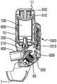
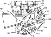
图1是根据有利的第一实施方式的处于息止位置的流体产品分配装置的示意性横截面图;Figure 1 is a schematic cross-sectional view of a fluid dispensing device in a rest position according to an advantageous first embodiment;
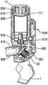
图2是与图1相似的视图,但在盖打开且在吸入之前;Figure 2 is a view similar to Figure 1, but with the lid open and before inhalation;
图3是与图2相似的视图,但在吸入之后;Figure 3 is a view similar to Figure 2, but after inhalation;
图4是与图2相似的视图,示出了一实施变型;Figure 4 is a view similar to Figure 2, showing a variant implementation;
图5是与图4相似的视图,但在吸入之后;Figure 5 is a view similar to Figure 4 but after inhalation;
图6是图1的装置在吸入之前的示意性正视图;Figure 6 is a schematic front view of the device of Figure 1 prior to inhalation;
图7是与图6相似的视图,但在吸入之后;Figure 7 is a view similar to Figure 6, but after inhalation;
图8是图1的装置的一实施变型在组装之前的示意性截面图;Fig. 8 is a schematic cross-sectional view of an embodiment variant of the device of Fig. 1 before assembly;
图9是与图8相似的视图,但装置正在组装中;Figure 9 is a view similar to Figure 8, but with the device being assembled;
图10是图9的装置的一部分在压接之前的详细示意图;Figure 10 is a detailed schematic view of a portion of the device of Figure 9 prior to crimping;
图11是与图10相似的视图,但在压接之后;Figure 11 is a view similar to Figure 10, but after crimping;
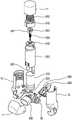
图12是根据有利的第二实施方式的流体产品分配装置的示意性分解透视图;Figure 12 is a schematic exploded perspective view of a fluid dispensing device according to an advantageous second embodiment;
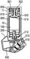
图13至图15是图12的装置的示意性横截面图,分别处于息止位置、在盖打开且在吸入之前、和在吸入之后;Figures 13 to 15 are schematic cross-sectional views of the device of Figure 12, respectively in the rest position, with the lid open and before inhalation, and after inhalation;
图16至图18是图13至图15的装置的锁件的示意性放大图,分别在吸入之前、在开始吸入时、以及在吸入完毕时;Figures 16 to 18 are schematic enlarged views of the lock of the device of Figures 13 to 15, respectively before inhalation, at the beginning of inhalation, and at the end of inhalation;
图19至图22是阀件释放系统在其致动和再加载的不同步骤期间的示意性详图;Figures 19 to 22 are schematic details of the valve release system during different steps of its actuation and reload;
图23是推压件的剖切的示意性透视图;Figure 23 is a schematic perspective view of a cutaway of the push member;
图24是阀件释放系统的操纵杆的示意性透视图;Figure 24 is a schematic perspective view of the lever of the valve member release system;
图25是阀件释放系统的推压元件的示意性透视图;Figure 25 is a schematic perspective view of a biasing element of the valve release system;
图26是致动件的示意性透视图;Figure 26 is a schematic perspective view of an actuator;
图27是盖的示意性透视图;Figure 27 is a schematic perspective view of the cover;
图28是触发元件的示意性透视图;Figure 28 is a schematic perspective view of a trigger element;
图29是锁定元件的示意性透视图。Figure 29 is a schematic perspective view of a locking element.
具体实施方式Detailed ways
在本说明书中,表述“上部”、“下部”、“上”和“下”参考尤其是在图1至图9和图13至图15上示出的装置的位置而言。表述“轴向”、“径向”除另有说明外是参考阀的竖直中心轴线而言的。表述“近侧”和“远侧”是参考口腔接嘴而言的。In this description, the expressions "upper", "lower", "upper" and "lower" refer in particular to the position of the device shown on FIGS. 1 to 9 and 13 to 15 . The expressions "axial", "radial" refer to the vertical central axis of the valve unless otherwise stated. The expressions "proximal" and "distal" are with reference to the mouthpiece.
本发明更具体地应用于用于口腔分配的气雾剂阀类型的吸入装置,如下面将更详细描述的,但是本发明也可以应用于其它类型的吸入装置,例如鼻式吸入装置。The invention applies more particularly to inhalation devices of the aerosol valve type for oral dispensing, as will be described in more detail below, but the invention may also be applied to other types of inhalation devices, such as nasal inhalation devices.
附图示出本发明的各种有利的实施方式,但是当然以下描述的一个或多个构成件可以以不同的方式实施,同时提供相似的或等同的功能。The drawings show various advantageous embodiments of the invention, but of course one or more of the constituents described below may be implemented in a different way, while providing a similar or equivalent function.
参考附图,装置包括设有口腔接嘴400的主体10。Referring to the drawings, the device comprises a
主体10可以整体制成,或可以由彼此组装在一起的多个零件制成。图12示出了一示例,其中,主体10由两个半壳形成,但也可以有其他的实施方式。在下面的描述中,将使用数字标号10整体指代主体。The
该口腔接嘴400限定分配孔,在使用装置时使用者将通过该分配孔吸入。口腔接嘴400可以与主体10一体制成。但在附图上示出的实例中,该口腔接嘴组装在主体10的下部部分上。The
设置可拆卸的保护盖1用于覆盖所述口腔接嘴400,尤其是在存储时期中。盖1可移动,优选地安装成在图1、8、9和13中示出的关闭位置和图2至7、14和15中示出的打开位置之间在主体10上枢转。A removable
主体10容纳:储存器100,该储存器容纳待分配的产品和推进剂气体,如HFA型的气体;计量阀200,该计量阀安装在所述储存器100上,用以有选择地分配产品。计量阀200包括阀体和阀件210,在致动时阀件相对于所述阀体、并因此相对于储存器100在息止位置和致动位置之间可轴向移动。该计量阀200可以是任何合适的类型。该计量阀可以通过适当的固定元件固定到储存器100,固定元件优选地是卷边罩,优选地还插置有颈部垫圈。The
有利地,在致动时,阀件210相对于主体10固定,是储存器100相对于主体10在远侧位置和近侧位置之间轴向移动,该远侧位置是息止位置,该近侧位置是致动位置。Advantageously, upon actuation, the
所述计量阀200的阀件210的出口孔经由通道连接到所述口腔接嘴400,通过该口腔接嘴使用者吸入分配的产品。已知地,所述阀件210接纳在阀件井700中,该阀件井至少部分限定了所述通道。The outlet opening of the
致动件800有利地围绕储存器100组装。该致动件800包括围绕储存器100布置在主体10中的中空的套筒。推压件810安装在所述致动件800的远侧径向边缘上,所述推压件810接纳在固定到所述主体10的上部轴向边缘上的罩壳元件11中。在所述罩壳元件11的底部和所述推压件810之间,设置弹簧850。在息止位置,直到吸入,弹簧850受预施应力,因此在推压件810上施加轴向力F,该推压件将该轴向力传递到致动件800。致动件800可相对于所述主体10在息止位置与致动位置之间轴向移动,尤其是滑动。致动件800的下部边缘802与盖1配合,使得在盖1的关闭位置,所述致动件800被锁定在息止位置,下部边缘802止挡在所述盖1的一部分3上。此外,所述盖1包括凸轮4,当盖1从其打开位置向其关闭位置回返时,该凸轮4与所述下部边缘802配合,用以使所述致动件800从其致动位置朝向其息止位置回返。当致动件800朝向其息止位置返回时,致动件还使推压件810回返,这引起弹簧850压缩。因此,在每次致动之后,当使用者闭合盖1时,弹簧850就再次被上紧。
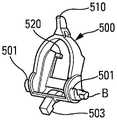
装置包括在锁定位置和致动位置之间可移动和/或可变形的锁定元件500,在该锁定位置,所述计量阀200不能被致动,在该致动位置,所述计量阀200能够被致动。The device comprises a
锁定元件500有利地安装成能围绕轴线B(图16至图18中更清楚示出)在锁定位置和致动位置之间在主体10上枢转。The locking
在吸入之前,所述锁定元件500处于锁定位置,正是使用者通过口腔接嘴400的吸入使所述锁定元件500朝向其致动位置移动和/或变形。换言之,只要使用者不进行吸入,就不可能致动计量阀200,并且只有当使用者进行吸入时,才能通过使储存器100在主体10中轴向移动致动所述计量阀200。Prior to inhalation, the locking
如下面将更详细描述的,锁定元件500在锁定位置阻止致动件800在主体10中轴向移动。在吸入时,该锁定元件500移动和/或变形,使得其不再锁定致动件800在主体10中的轴向移动。因此,在吸入之后,致动件800的这种轴向移动引起储存器100的轴向移动,因此引起计量阀200致动以及引起与该吸入同步地分配一剂量产品。As will be described in more detail below, the locking
因此,在没有吸入的情况下,不存在由于使用者并不吸入的意外或不完全致动而导致一剂量的活性产品损失的任何风险。Thus, without inhalation, there is no risk of loss of a dose of active product due to accidental or incomplete actuation by the user without inhalation.
在盖1的关闭位置,盖1的锁定部分2与锁定件500的突出部分503配合,以将锁定件锁定在锁定位置上,尤其如图1所示。在盖1打开时,消除了这种锁定。In the closed position of the
打开盖1因此释放了盖在关闭位置时提供的两种锁定阻止,即:一方面,锁定阻止致动件800的轴向移动;和另一方面,对锁定件500的枢转锁定阻止。Opening the
装置包括包括由使用者的吸入控制的触发系统,当使用者通过口腔接嘴400进行吸入时,该触发系统用于使锁定元件500从其锁定位置向其致动位置移动和/或变形。The device includes a trigger system controlled by the user's inhalation for moving and/or deforming the
该触发系统包括在吸入的作用下可变形和/或可移动的吸入敏感件60,该吸入敏感件60适于在其变形和/或移动时允许所述锁定元件500从其锁定位置向其致动位置移动和/或变形。The trigger system comprises a deformable and/or movable suction
如下面将更详细描述的,吸入敏感件可以实施成可变形的空气腔室60的形式,例如多层折叠式箱或可变形袋。As will be described in more detail below, the inhalation sensitive member may be implemented in the form of a
这样,吸入式控制的触发系统没有位于使用者的呼吸流中,而由特殊的腔室即可变形的空气腔室60形成。这不同于借助在呼吸流中移动/变形的活门阀运行的那些系统,在那些系统中,在触发后,使用者将吸取位于活门阀两侧的空气。在此,触发系统在负压下运行,使用者只吸取在可变形的空气腔室60变形前处于可变形的空气腔室内的少量空气。根据本发明的吸入式控制的触发系统因此稳定得多,效率高得多。In this way, the inhalation-controlled trigger system is not located in the user's breath flow, but is formed by a special chamber, namely the
锁定元件500包括至少一个、优选地为两个锁定延伸部501,各锁定延伸部在锁定位置与致动件800的轴向突出部801配合。图29示出该锁定元件500的透视图。The locking
当锁定元件500尤其通过围绕轴线B枢转而朝向其致动位置移动时,每个锁定延伸部501移动脱离与相应的轴向突出部801的接触。特别地,所述锁定元件500与每个锁定延伸部501相邻地包括轴向凹槽502,图18中可见该轴向凹槽,相应的轴向突出部801可在轴向凹槽中轴向滑动,以因此允许所述致动件800在所述主体10中轴向滑动,引起储存器100的轴向移动,以及引起阀200致动并分配一剂量流体产品。When the
锁定元件500通过触发元件600保持在锁定位置。图28示出该触发元件600的透视图。该触发元件600有利地安装成围绕轴线C(图16和图18中可见)在锁紧位置和释放位置之间在主体10上能枢转,在锁紧位置,该触发元件将所述锁定元件500锁定在其锁定位置,在释放位置,该触发元件不再锁定锁定元件500。The locking
有利地,轴线B和轴线C是平行的。Advantageously, axis B and axis C are parallel.
锁定元件500和触发元件600共同限定一锁件。特别地,所述触发元件600包括锁紧肩部610,锁紧肩部在锁紧位置与锁定元件500的锁紧突出部510配合,从而阻止所述锁定元件500枢转到其锁定位置以外。因此,当所述触发元件600位于锁紧位置时,该触发元件阻止锁定元件500朝向其致动位置移动,这锁定阻止了储存器100的轴向移动,并因此锁定阻止了对计量阀200的致动。The locking
本发明的锁定系统因此包括两级:第一级,由锁定元件500和触发元件600之间的锁件形成;第二级,由锁定元件500和触发元件600之间的锁定形成。The locking system of the invention thus comprises two stages: a first stage, formed by the lock between the locking
该锁定系统允许通过吸入引起的很小的力实现很大的力(一般大约为40N-45N)的解锁。当其经受由弹簧850通过推压件810在致动件800上的按压所产生的力F(例如45N)时,锁定元件500停止致动件800的平移。该锁定元件500与触发元件600相互作用,锁定元件被触发元件600锁定/释放。所述触发元件600的移动由吸入控制。The locking system allows unlocking with very high force (typically around 40N-45N) with very little force induced by suction. The locking
锁定系统的几何形状允许非常大的通常约为100倍的力放大(被解锁力/解锁力)。The geometry of the locking system allows a very large force amplification (unlocked force/unlocking force) of typically about 100 times.
锁定元件500和触发元件600优选具有两个间隔开的几何接触点:The locking
-第一接触点,由在锁紧肩部610和突出部510之间限定的锁件形成,有利地靠近触发元件600的枢转轴线C;- a first point of contact, formed by the lock defined between the locking
–远离第一接触点的第二接触点,通过锁定元件500的侧向突出部分520与触发元件600的支撑表面620的配合形成;有利地,该第二接触点在锁紧位置与触发元件600的轴线C的距离大于所述轴线C与第一接触点之间的距离;有利地,该第二接触点是当使用者开始吸入时在致动所述装置时断开的第一接触点。- a second contact point remote from the first contact point, formed by the cooperation of the
在锁定位置,在打开盖1后并在吸入之前,由弹簧850在致动件800上产生的轴向力F由致动件800的轴向突出部801在延伸部分501处施加在锁定元件500上,使得推动所述锁定元件500沿第一方向S1转动,图16可见,从而加强了锁件的关闭位置并使其稳定。In the locked position, after opening the
由吸入产生的解锁力通过呼吸敏感件60施加到触发元件600上,优选地在距枢转轴线C一定距离的点630处。该解锁力旨在使所述触发元件600沿与方向S1相反的方向S2转动,如图17所示。The unlocking force generated by inhalation is applied to the
锁定元件500经受的力矩由作用力轴线和所述锁定元件500的枢转轴线B之间的距离d控制,沿该作用力轴线作用力F施加在锁定元件的锁定延伸部501上。寻求尽可能小的距离d,使得力矩尽可能地小。图16中可见的该距离d为非零值,小于2mm,有利地小于1mm。The moment experienced by the locking
触发元件600经受的力矩由作用力轴线和所述触发元件600的枢转轴线C之间的距离d'控制,该作用力轴线承载触发元件600经受的来自锁定元件500的作用力F’。在此同样,寻求尽可能小的距离d',使得力矩尽可能地小。图16中可见的该距离d'为非零值,小于2mm,有利地小于1mm。The moment experienced by the
借助于该锁件的力系,用于使触发元件600枢转所需的作用力非常小并且可以由吸入敏感件60产生,从而允许将由吸入产生的负压转变成解锁作用力。By means of the force train of the lock, the force required for pivoting the
有利地,如图4和图5的变型中示出的,口腔接嘴400包括一个或多个与主体10的内部相连的开口410。该至少一个开口410在息止时和在吸入开始时由活门420关闭,从而吸入流最初主要传递到吸入式的触发系统,在该示例中即可变形的空气腔室60。这允许优化这种吸入式的触发。当锁定元件500在吸入的作用下朝向其致动位置移动时,储存器100因此相对于主体10轴向移动,用以致动计量阀200以分配一剂量的流体产品时,所述致动元件800,或变型中所述储存器100,使所述活门420向打开位置移动。当所述至少一个开口410因此被打开时,在致动过程中,产生空气抽吸,这允许增加吸入流。这优化了在剂量分配和使用者的吸入之间的同步,有利于剂量在使用者的肺中的良好分配。Advantageously, as shown in the variant of FIGS. 4 and 5 , the
有利地,触发元件600从主体10的外部可触及。这允许在需要的情况下手动移动触发元件600,以能够甚至在没有吸入的情况下、例如如果在应接收流体产品剂量的人不能实施足够的吸入,实施致动计量阀200。因此这是一种安全措施。这还允许在阀是传统的需要启动的情况下,实施阀的这种启动。Advantageously, the
在附图所示的实施方式中,吸入敏感件60以可变形的空气腔室的形式制成。有利地,该空气腔室包括可变形的膜片,该可变形的膜片一方面连接到主体10和另一方面连接到触发元件600。有利地,如在附图上可见,膜片呈多层折叠式箱的形状,形成大体上密封的腔室。其它形状也是可行的,尤其是简单的袋或膜件。一触柱可以将所述膜片61固定到所述触发元件600的孔或边缘630。In the embodiment shown in the figures, the
当吸入时,可变形的膜片在由吸入产生的负压的作用下变形和/或收缩,从而引起触发元件600从其锁紧位置朝向其释放位置移动。这允许打开在锁定元件500和触发元件600之间限定的锁件,并因此允许所述锁定元件500从其锁定位置朝向其致动位置移动。When inhaled, the deformable membrane deforms and/or contracts under the negative pressure generated by the inhalation, thereby causing the
阀200因此只在吸入时刻被致动,使得流体产品剂量与吸入同时地排出到分配孔之外。
在息止位置,盖1关闭,推压件810不与储存器100接触,如图1所示。因此,在该息止位置,弹簧850的力由推压件810施加在致动件800上,致动件800将该力传递到盖1。因此,在装置储存期间,没有任何应力施加在阀200上,这限制、甚至消除了阀漏液风险和/或阀故障的风险。In the rest position, the
当使用者希望使用装置时,其打开盖1。打开盖,使用者就取消了通过盖1对致动件800的轴向锁定,因此取消了通过盖1对锁定元件500的枢转锁定。在该位置,通过轴向锁定致动件800的轴向突出部801的锁定元件500的锁定延伸部501,锁定致动件800并阻止致动件800在主体10中轴向滑动。如图2所示,在该已加载位置(盖打开,吸入前),推压件810仍没有与储存器100接触。因此,同样在该位置,弹簧850的力通过推压件810施加在致动件800上,致动件800将该力传递到锁定元件500,锁定元件将该力传递到触发元件600。因此,在吸入前,没有任何应力施加在阀200上,这限制、甚至消除了阀漏液风险和/或阀故障的风险。When the user wishes to use the device, he opens the
当使用者通过口腔接嘴400进行吸入时,使用者使吸入敏感件60的可变形的膜片变形,这将使固定到所述可变形的膜片的触发元件600枢转。触发元件600的该移动将释放在触发元件600的锁紧肩部610和锁定元件500的突出部510之间形成的锁件。在由致动件800传递的由轴向力F的作用下,锁定元件500将枢转,从而允许所述致动件800的轴向滑动。因此,与所述致动件800连成一体的推压件810与储存器100接触,因此引起所述储存器100在主体10中朝向其分配位置的轴向移动,并因此致动阀200。When the user inhales through the
同时,在图4和图5的变型中,致动件800(或变型中储存器100)将打开活门420。At the same time, in the variant of FIGS. 4 and 5 , the actuator 800 (or the
在吸入结束时,装置有利地包括信号部件,以向使用者指示其应该闭合盖1。信号部件可能包括可视指示器,如图6和图7中所示。在该示例中,窗口15形成在主体10中,通过该窗口可从外部看到致动件800的涂色部分,该涂色部分形成指示部件。因此,在息止位置或在已加载位置,当盖1打开且在吸入之前,窗口15可以指示浅色,例如绿色,而在吸入之后,则在窗口15中显示的是深色,例如红色。当然,任何其他类似的实施方式也是可以的。At the end of inhalation, the device advantageously includes signaling means to indicate to the user that he should close the
在变型中,可以看到有多个窗口15。一个窗口(或多个窗口)15可以在装置上不同地定位,例如定位在主体10的上部中,或定位在罩壳11上。变型中,在窗口15中显示的指示部件可以包括符号、数字、字母或任何其他有用的提醒使用者的指示标。指示部件可以直接在致动件800上形成、例如通过移印形成,或可在固定到致动件800上的零件上形成。指示部件可在致动时活动的任何其他活动零件上实现,其它零件例如推压件810、锁定元件500、触发元件600、吸入敏感件60。In a variant, a plurality of
在另一变型中,信号部件可以包括声音指示器,例如扬声器,声音指示器发出使用者能够听到的声音,以向使用者指示盖1应闭合。In another variant, the signaling means may comprise an audio indicator, such as a loudspeaker, which emits a sound audible to the user to indicate to the user that the
当使用者闭合盖1时,致动件800被所述盖1朝向致动件的息止位置轴向推回,使得所述储存器100能够在阀200的复位弹簧的作用下在主体10中朝向其息止位置轴向上升;并且同时计量阀的阀件210返回到息止位置,用新一剂量的流体产品填充阀室。触发元件600尤其通过膜片的弹性返回到其初始位置。锁定元件500返回到其锁定位置。When the user closes the
装置于是准备好另一次使用。The device is then ready for another use.
在图8至图11示出的一有利的实施变型中,该装置的最终组装对于销售与吸入同步分配流体产品的流体产品分配装置的药物实验室来说简化了。实际上,在大部分现有的装置中,装填有活性成分的储存器插入在主体中,然后需要将多个零件定位在该储存器上方,这为生产效率以及组装简便性带来不便。为消除这一缺陷,本发明有利地设置了预组装由推压件810、弹簧850和罩壳11形成的子组件。在通过例如用加热工具O使罩壳11的中心轴向套筒110的下部轴向边缘111发生热变形——其中围绕该中心轴向套筒组装推压件810和弹簧850,来组装这三个零件时,该子组件被预施应力。所述下部轴向边缘111因此变形用以制造保持凸缘,该保持凸缘将推压件810和弹簧850保持在罩壳11中。如此形成的该子组件因此可以在单一组装操作中,例如通过旋紧或卡扣组装在主体10上。因此导致在药物实验室组装线上仅需两项操作:将储存器10插置到主体10中(图8),以及将所述子组件组装在主体10上(图9)。在进行该组装时,布置在主体10中的致动件800会与推压件810配合,以将推压件在罩壳11中轴向推动,并因此使弹簧850上紧。在旋紧的情况中,该系统还可以允许更换弹簧。实际上,出于环保考虑,装置可以重复使用并重新装填,尤其是以避免丢弃过多的塑料配件和/或过多的电子配件。In an advantageous embodiment variant shown in FIGS. 8 to 11 , final assembly of the device is simplified for pharmaceutical laboratories that sell fluid dispensing devices that dispense fluid simultaneously with inhalation. In fact, in most existing devices, the reservoir filled with the active ingredient is inserted in the body, and several parts need to be positioned above the reservoir, which inconveniences the production efficiency and ease of assembly. In order to eliminate this drawback, the invention advantageously provides for the pre-assembly of the subassembly formed by the
在图12至图15和图19至图22示出的一有利的实施例中,装置包括阀件自动释放系统,该阀件自动释放系统自动使阀200的阀件210在阀致动之后朝向其息止位置回返,而无论盖1的位置如何,也无论致动件800的位置如何。因此,在该变型中,不存在故障风险如下一剂量不完全的风险,即使使用者延迟闭合盖也如此。In an advantageous embodiment shown in FIGS. 12 to 15 and FIGS. 19 to 22 , the device includes an automatic valve member release system that automatically directs the
阀件自动释放系统包括如下附加零件:The valve automatic release system includes the following additional parts:
-两个操纵杆901、902;- two
-推压元件910;- pushing
-操纵杆弹簧920。-
推压元件910旨在与储存器100接触,推压元件和推压件810相连并且间置有操纵杆弹簧920。有利地,在吸入之前,推压元件910特别轻微地从储存器100轴向错移开,使得在该位置,推压元件不将任何应力传递至所述储存器100或传递至阀200。仅当使用者吸入并释放致动件800的轴向移动时,推压元件910才与储存器100接触。The
每个操纵杆901、902均通过触柱905以能枢转的方式组装在所述推压件810的凸轮815中,并且与所述推压元件910配合。Each
当使用者进行吸入时,致动件800以及因此推压件810在弹簧850的作用下朝下轴向移动。该弹簧作用力通过操纵杆901、902传递到推压元件910,推压元件将该作用力传递到储存器100,因此引起所述储存器100的轴向移动并致动阀200。When the user inhales, the actuating
阀件释放系统因此目的在于在吸入之后释放力从弹簧850向储存器100的传递,以允许所述储存器100朝向其息止位置返回,而无论致动件800的位置如何。这允许在装置还处于加载下一剂量的适当位置时,在吸入之后立即加载该下一剂量到阀200中,而不存在剂量不足的风险,例如不存在忘记闭合盖1的情况下导致剂量不足的风险。The valve release system is thus intended to release the transmission of force from the
该阀件释放系统的运行情况如下:The valve release system operates as follows:
在锁紧位置,在吸入之前,如图19中可见,操纵杆901和902抵靠在推压元件910的肩部911上。在相对侧上,这些操纵杆与在罩壳11中形成的锁紧指状件115接触,锁紧指状件从所述罩壳底部朝下轴向延伸。这些锁紧指状件115阻止操纵杆901、902枢转脱离与推压元件的肩部911的接触。在该位置,弹簧850的力因此通过操纵杆901、902传递到推压元件910,并因此传递到储存器100。In the locked position, before inhalation, as can be seen in FIG. 19 , the
当致动件800到达致动位置时——阀200则已被致动以分配一剂量,推压件810、推压元件910和操纵杆901、902已相对于罩壳11朝下轴向滑动,如图20可见。在该位置,操纵杆901、902不再与罩壳11的锁紧指状件115配合。操纵杆于是能够在推压件810中枢转,直至操纵杆不再与推压元件的肩部911接触。有利地,在通过阀排出一剂量之后、但在该阀致动行程结束之前,产生推压元件910的释放。When the
当操纵杆901、902不再与推压元件的肩部911接触时,操纵杆中的每一个操纵杆与所述推压元件910的开口912相面对,使得储存器100能够在阀200的复位弹簧的作用下向其息止位置再次上升,同时操纵杆901、902穿过所述孔912,如图21所示。当储存器100朝向其息止位置返回时,推压元件910与储存器100一起相对于推压件810和相对于操纵杆901、902向上轴向滑动。在该移动时,刚度应低于阀200的弹簧的刚度的操纵杆弹簧920压缩。When the
当装置再次装载好时,如图22所示,当使用者闭合盖1时,致动件800和推压件810朝向其各自的息止位置返回,同时压缩弹簧850。在该移动时,操纵杆901、902承受通过操纵杆弹簧920施加的力,其推动操纵杆旋转,如箭头F1所示。只要操纵杆901、902还处于推压元件910的孔912中,操纵杆就不会枢转,操纵杆与推压件810轴向移动,如箭头F2所示。当操纵杆与罩壳11的锁紧指状件115接触时,触柱905被迫在凸轮815中朝外径向移动,如箭头F3所示,这允许操纵杆901、902返回到罩壳11的锁紧指状件115附近。当致动件800和推压件810到达其各自的息止位置时,操纵杆901、902离开推压元件的孔912,操纵杆弹簧920将所述操纵杆带回抵靠在推压元件的肩部911上。When the device is loaded again, as shown in FIG. 22 , when the user closes the
为保证装置的可靠运行,阀件释放系统应该仅在保证产生分配剂量的足够行程之后才被致动。由于零件的制造允差,有利地在推压元件910和储存器100之间设置缓冲元件。该缓冲元件应减慢或错开阀件释放系统的致动,缓冲元件可以是弹性元件,如弹簧或可压缩零件,例如是弹性体制的。该缓冲元件的强度一方面应大于在阀件210致动位置的阀200的弹簧的力,使得在缓冲元件变形前首先是阀200获得致动,另一方面该缓冲元件的强度应小于在致动件800致动位置的弹簧850的力,以保证缓冲元件在致动行程结束时压缩。在变型中,还可以使用由作动筒或由充满空气或流体且具有泄流孔的可变容积的腔室形成的缓冲元件。To ensure reliable operation of the device, the valve release system should only be actuated after sufficient travel has been ensured to produce a dispensed dose. Due to manufacturing tolerances of the parts, it is advantageous to provide a cushioning element between the pushing
在一有利实施例中,装置可以包括剂量计数器1000,如图1至图9所示,剂量计数器可以是机械的或电子的,有利地组装到主体10中。这种计数器还可以与图12至图22的实施例相关。该计数器100尤其可以检测致动件800或储存器100的位移。在变型中,计数器可以连接到传感器,尤其是膜片式传感器,其检测流体产品剂量例如在阀件井中的分配。致动这种计数器的其它部件也是可行的,例如检测计量阀200的阀件210相对于阀体的位移。In an advantageous embodiment, the device may comprise a
在计数器是电子计数器时,计数器应能够具有用于在其整个储存期间直到其第一次使用运行的足够的电能。之后,在其整个使用期间,至少直到药物失效日期,电池应具有足够的容量,例如用以与使用者(查看剩余剂量数量)通信和/或与第三方应用通信。为避免电池过多耗电,需要在第一次使用之前减少电路板耗能。为此,使电子器件有利地处于待机模式,极少耗电,直到第一次使用时。为“唤醒”电子器件,要求使用者通过吸入第一剂量(如果装置配有无需启动式的阀)或通过实施启动(如果装置配有传统的阀)来致动所述装置。第一次致动使致动件800在主体10中下降。致动件800的一部分于是将对计数器1010施加压力,如图2至图5所示,这使得封闭电流回路。装置这时检测电流强度变化,从而将唤醒电子器件,并将计数器置于正常工作状态。Where the counter is an electronic counter, the counter should be able to have sufficient electrical energy for its operation throughout its storage period up to its first use. Thereafter, throughout its lifetime, at least until the drug expiration date, the battery should have sufficient capacity, for example to communicate with the user (to see the number of remaining doses) and/or communicate with third party applications. To avoid excessive battery drain, it is necessary to de-energize the board before first use. To this end, the electronic device is advantageously placed in a standby mode, consuming very little power until first used. To "wake up" the electronics, the user is asked to actuate the device by inhaling the first dose (if the device is equipped with a no-actuator valve) or by performing an activation (if the device is equipped with a traditional valve). The first actuation lowers the
作为变型,或附加地,装置可包括加速度计。As a variant, or in addition, the device may comprise an accelerometer.
该加速度计可具有如下多种功能:The accelerometer can have various functions as follows:
-该加速度计可以用于检验装置在使用前是否经过充分摇晃;实际上,在压力储存器中保存的大部分药物或多或少属于可溶解药物,因此需要在吸食剂量时混合药物;如果电路通过加速度计捕捉到装置未经过摇晃,那么例如通过在其智能手机中的应用或在装置屏幕上可以通知使用者;- the accelerometer can be used to verify that the device has been shaken sufficiently before use; in fact most of the medicines held in pressurized reservoirs are more or less soluble medicines and therefore need to be mixed when the dose is inhaled; if the circuit The absence of shaking of the device is captured by the accelerometer, and the user can be notified, for example, through an application in his smartphone or on the screen of the device;
-有些人员在想致动装置时倒持装置;当装置倒置时,即储存器放置在阀的下方时,液体不能进入阀的剂量腔室中,从而导致在加载剂量时剂量减少甚至完全加载不到剂量;加速度计可以检测患者是否倒持装置,优选地在吸食剂量时之前,例如通过发出嘀嘀声和/或在屏幕上显示和/或在智能手机上显示,来通知使用者所述装置方向不正确;- Some people hold the device upside down when wanting to actuate it; when the device is upside down, i.e. when the reservoir is placed under the valve, liquid cannot enter the valve's dosing chamber, resulting in a reduced dose or even no loading at all when loading a dose to the dose; the accelerometer can detect if the patient is holding the device upside down, preferably prior to ingesting the dose, e.g. by beeping and/or displaying on the screen and/or displaying on a smartphone, to notify the user of the device wrong direction;
-加速度计的另一个作用在于使用装置以省电;当装置放置在包里或裤子口袋里、甚至放置在桌面上时,装置处于待机模式;在此期间,计数器屏幕以及搭载的大部分电子器件处于待机模式,这允许大大降低耗电;当使用者持握装置时,加速度计检测到运动并唤醒电子器件,以将计数器调至正常工作状态,该选择因此允许降低搭载的电池的容量,因此对环境产生更小的负面影响。- Another role of the accelerometer is to use the device to save power; when the device is placed in a bag or pants pocket, or even placed on a table, the device is in standby mode; during this time, the counter screen and most of the on-board electronics In standby mode, this allows a significant reduction in power consumption; when the user holds the device, the accelerometer detects motion and wakes up the electronics to reset the counter to normal operation, this option thus allows reducing the capacity of the battery onboard, so Less negative impact on the environment.
装置还包括信号发送部件,用于尤其远程地传输与装置的致动相关的信息。特别地,主体和/或盖和/或计数器可以包括信号发送模块,用于与任何远程装置进行远程通信。有利地设置合适的供电部件。The device also comprises signaling means for transmitting, in particular remotely, information related to the actuation of the device. In particular, the body and/or the cover and/or the counter may comprise a signaling module for remote communication with any remote device. Suitable power supply components are advantageously provided.
有利地,电子模块可以包括电路板,电路板包括发送脉冲的电开关。电子模块还可以包括显示装置和/或使用蓝牙或Wifi连接用以将信息发送到附接的外围设备。可以设置合适的传感器,如流量传感器和/或压力传感器,用以检测吸入流的多种参数。Advantageously, the electronic module may comprise a circuit board comprising electrical switches for sending pulses. The electronics module may also include a display and/or use a Bluetooth or Wifi connection to send information to attached peripherals. Suitable sensors, such as flow sensors and/or pressure sensors, may be provided to detect various parameters of the suction flow.
开关可以借助于致动件和/或锁定元件和/或触发元件和/或吸入敏感件的运动被致动。The switch can be actuated by means of movement of the actuating element and/or the locking element and/or the triggering element and/or the suction sensitive element.
信号发送部件与对有效发送的每一剂量进行计数的剂量计数器以及与本发明的与吸入同步的装置相关联地,允许以绝对可靠的方式例如向医生或希望监控使用者使用吸入装置的任何其它人传递每一剂量分配。与吸入同步的装置保证在每次使用者致动装置时使用者吸入,并且计数器记录分配的每一剂量以及各种相关参数,如每次分配的时间戳。医生因此可以非常准确地了解使用者使用装置的状况。The signaling means, in association with the dose counter counting each dose effectively delivered, and with the device of the invention synchronized with the inhalation, allow in an absolutely reliable manner, e.g. Human passes each dose dispensed. Devices synchronized with inhalation ensure that the user inhales each time the device is actuated by the user, and a counter records each dose dispensed along with various relevant parameters, such as the time stamp of each dispense. The doctor can thus have a very accurate picture of how the user is using the device.
本发明尤其是可适用于通过使用以下类型的制剂量治疗哮喘发作或BPCO(慢性阻塞性肺病):沙丁胺醇、阿地溴铵、福莫特罗、噻托溴铵、布地奈德、氟替卡松、茚达特罗、格隆溴铵、沙美特罗、乌美溴铵、维兰特罗、奥达特罗、力克地或这些制剂量的任何组合。The invention is especially applicable to the treatment of asthma attacks or BPCO (Chronic Obstructive Pulmonary Disease) by using doses of the following types of preparations: albuterol, aclidinium bromide, formoterol, tiotropium bromide, budesonide, fluticasone, indene Dacaterol, glycopyrrolate, salmeterol, umeclidinium, vilanterol, olodaterol, racatid, or any combination of these doses.
本发明已经参照有利的实施方式和实施变型进行了描述,但是本领域技术人员当然可以对其进行任何修改,而不超出由所附权利要求限定的本发明的保护范围。The invention has been described with reference to advantageous embodiments and implementation variants, but a person skilled in the art can of course make any modifications thereto without departing from the scope of protection of the invention as defined by the appended claims.
Claims (20)
Applications Claiming Priority (3)
| Application Number | Priority Date | Filing Date | Title |
|---|---|---|---|
| FR1901076AFR3092250B1 (en) | 2019-02-04 | 2019-02-04 | Fluid dispenser device synchronized with inhalation |
| FR1901076 | 2019-02-04 | ||
| PCT/FR2020/050170WO2020161420A1 (en) | 2019-02-04 | 2020-02-03 | Device for the inhalation-synchronized dispensing of a fluid product |
Publications (2)
| Publication Number | Publication Date |
|---|---|
| CN113382760A CN113382760A (en) | 2021-09-10 |
| CN113382760Btrue CN113382760B (en) | 2022-11-15 |
Family
ID=67185261
Family Applications (1)
| Application Number | Title | Priority Date | Filing Date |
|---|---|---|---|
| CN202080012422.4AActiveCN113382760B (en) | 2019-02-04 | 2020-02-03 | Device for dispensing a fluid product in synchronism with inhalation |
Country Status (7)
| Country | Link |
|---|---|
| US (1) | US12186480B2 (en) |
| EP (1) | EP3921002B1 (en) |
| JP (1) | JP7463384B2 (en) |
| CN (1) | CN113382760B (en) |
| BR (1) | BR112021015344A2 (en) |
| FR (1) | FR3092250B1 (en) |
| WO (1) | WO2020161420A1 (en) |
Families Citing this family (5)
| Publication number | Priority date | Publication date | Assignee | Title |
|---|---|---|---|---|
| USD1006214S1 (en)* | 2020-02-14 | 2023-11-28 | Aptar France Sas | Inhaler |
| USD983961S1 (en)* | 2020-02-14 | 2023-04-18 | Aptar France Sas | Inhaler |
| USD995752S1 (en)* | 2020-02-14 | 2023-08-15 | Aptar France Sas | Inhaler |
| USD1006213S1 (en)* | 2020-02-14 | 2023-11-28 | Aptar France Sas | Inhaler |
| IL316077B2 (en)* | 2024-10-01 | 2025-06-01 | Stav Iyar | Dispenser for solid objects |
Citations (5)
| Publication number | Priority date | Publication date | Assignee | Title |
|---|---|---|---|---|
| CN1518464A (en)* | 2000-11-24 | 2004-08-04 | ��¬�����ϻ﹫˾ | Fluid product dispensing device |
| CN1617752A (en)* | 2001-12-28 | 2005-05-18 | 瓦卢瓦有限合伙公司 | Fluid product dispensing device |
| CN101511414A (en)* | 2006-07-25 | 2009-08-19 | 瓦卢瓦有限合伙公司 | Fluid product dispensing device |
| WO2018048795A1 (en)* | 2016-09-07 | 2018-03-15 | 3M Innovative Properties Company | Reset mechanism for an inhaler |
| CN109069767A (en)* | 2016-04-15 | 2018-12-21 | 阿普塔尔法国简易股份公司 | Distribute the device fluid dispensing product synchronous with sucking |
Family Cites Families (29)
| Publication number | Priority date | Publication date | Assignee | Title |
|---|---|---|---|---|
| US3456646A (en) | 1967-01-19 | 1969-07-22 | Dart Ind Inc | Inhalation-actuated aerosol dispensing device |
| US5119806A (en) | 1987-05-12 | 1992-06-09 | Glaxo Inc. | Inhalation device |
| US5060643A (en)* | 1990-08-07 | 1991-10-29 | Tenax Corporation | Breath-activated inhalation device |
| US5622163A (en)* | 1994-11-29 | 1997-04-22 | Iep Group, Inc. | Counter for fluid dispensers |
| US6082358A (en)* | 1998-05-05 | 2000-07-04 | 1263152 Ontario Inc. | Indicating device for aerosol container |
| GB0315791D0 (en)* | 2003-07-07 | 2003-08-13 | 3M Innovative Properties Co | Two component molded valve stems |
| GB0222295D0 (en) | 2002-09-25 | 2002-10-30 | 3M Innovative Properties Co | Breath actuated medicament dispensing devices |
| GB2398065A (en)* | 2003-10-16 | 2004-08-11 | Bespak Plc | Dispensing apparatus |
| US7219664B2 (en) | 2005-04-28 | 2007-05-22 | Kos Life Sciences, Inc. | Breath actuated inhaler |
| US20100175692A1 (en)* | 2005-05-10 | 2010-07-15 | Bang & Olufsen Medicom A/S | Forward metering valve |
| GB0518355D0 (en)* | 2005-09-08 | 2005-10-19 | Glaxo Group Ltd | An inhaler |
| US20080178872A1 (en) | 2006-12-01 | 2008-07-31 | Perry Genova | Dose selective breath actuated inhaler |
| US8225790B2 (en) | 2007-01-02 | 2012-07-24 | Astrazeneca Ab | Inhaler 624 |
| CN102131540B (en) | 2008-07-10 | 2015-04-22 | 邦及奥卢夫森美迪康股份公司 | Inhaler and method of operating same |
| US8469030B2 (en)* | 2009-12-01 | 2013-06-25 | Covidien Lp | Exhalation valve assembly with selectable contagious/non-contagious latch |
| WO2011130183A2 (en)* | 2010-04-11 | 2011-10-20 | Proteus Biomedical, Inc. | Apparatus, system and method for detection and delivery of a medicinal dose |
| KR102177660B1 (en)* | 2011-08-16 | 2020-11-12 | 쥴 랩스, 인크. | Low temperature electronic vaporization device and methods |
| FR2991185B1 (en) | 2012-05-31 | 2015-06-26 | Valois Sas | DEVICE FOR DISPENSING FLUID PRODUCT. |
| EP2953673A1 (en)* | 2013-02-06 | 2015-12-16 | Flextronics AP, LLC | Metered dose inhaler with an electronic dose counter |
| WO2014204511A2 (en)* | 2013-06-18 | 2014-12-24 | Isonea Limited | Compliance monitoring for asthma inhalers |
| US20160106935A1 (en)* | 2014-10-17 | 2016-04-21 | Qualcomm Incorporated | Breathprint sensor systems, smart inhalers and methods for personal identification |
| EP3220986B1 (en)* | 2014-11-20 | 2022-11-09 | Cognita Labs, LLC | Apparatus to measure, aid and correct the use of inhalers |
| US20160144142A1 (en)* | 2014-11-24 | 2016-05-26 | Jeff Baker | Metered dose respiratory training device and system |
| EP3393561B1 (en)* | 2015-12-21 | 2021-11-03 | Kindeva Drug Delivery L.P. | Auto-reset dose release firing system and medicinal inhaler comprising same |
| WO2017176704A1 (en)* | 2016-04-05 | 2017-10-12 | 3M Innovative Properties Company | Medicinal inhaler refill assemblies comprising a lockout mechanism |
| EP3445188A4 (en)* | 2016-04-22 | 2020-03-25 | Resolve Digital Health Inc. | An inhalation device, system and method |
| CN114177442A (en)* | 2016-11-18 | 2022-03-15 | 诺顿(沃特福特)有限公司 | Drug delivery device with electronics |
| GB201702406D0 (en)* | 2017-02-14 | 2017-03-29 | Norton (Waterford) Ltd | Inhalers and related methods |
| AU2019232610B2 (en)* | 2018-03-07 | 2021-12-16 | Astrazeneca Ab | Inhaler |
- 2019
- 2019-02-04FRFR1901076Apatent/FR3092250B1/enactiveActive
- 2020
- 2020-02-03JPJP2021545425Apatent/JP7463384B2/enactiveActive
- 2020-02-03EPEP20706793.5Apatent/EP3921002B1/enactiveActive
- 2020-02-03CNCN202080012422.4Apatent/CN113382760B/enactiveActive
- 2020-02-03USUS17/427,682patent/US12186480B2/enactiveActive
- 2020-02-03BRBR112021015344-6Apatent/BR112021015344A2/enunknown
- 2020-02-03WOPCT/FR2020/050170patent/WO2020161420A1/ennot_activeCeased
Patent Citations (5)
| Publication number | Priority date | Publication date | Assignee | Title |
|---|---|---|---|---|
| CN1518464A (en)* | 2000-11-24 | 2004-08-04 | ��¬�����ϻ﹫˾ | Fluid product dispensing device |
| CN1617752A (en)* | 2001-12-28 | 2005-05-18 | 瓦卢瓦有限合伙公司 | Fluid product dispensing device |
| CN101511414A (en)* | 2006-07-25 | 2009-08-19 | 瓦卢瓦有限合伙公司 | Fluid product dispensing device |
| CN109069767A (en)* | 2016-04-15 | 2018-12-21 | 阿普塔尔法国简易股份公司 | Distribute the device fluid dispensing product synchronous with sucking |
| WO2018048795A1 (en)* | 2016-09-07 | 2018-03-15 | 3M Innovative Properties Company | Reset mechanism for an inhaler |
Also Published As
| Publication number | Publication date |
|---|---|
| JP7463384B2 (en) | 2024-04-08 |
| FR3092250A1 (en) | 2020-08-07 |
| BR112021015344A2 (en) | 2021-09-28 |
| FR3092250B1 (en) | 2021-01-22 |
| US20220126037A1 (en) | 2022-04-28 |
| US12186480B2 (en) | 2025-01-07 |
| EP3921002B1 (en) | 2024-11-20 |
| EP3921002A1 (en) | 2021-12-15 |
| JP2022519602A (en) | 2022-03-24 |
| WO2020161420A1 (en) | 2020-08-13 |
| CN113382760A (en) | 2021-09-10 |
Similar Documents
| Publication | Publication Date | Title |
|---|---|---|
| CN113382762B (en) | Device for dispensing a fluid product in synchronism with inhalation and method for assembling a device | |
| CN113382760B (en) | Device for dispensing a fluid product in synchronism with inhalation | |
| CN109069767B (en) | Device for dispensing a fluid product with synchronized dispensing and inhalation | |
| US12178958B2 (en) | Device for the inhalation-synchronized dispensing of a fluid product | |
| JP6921856B2 (en) | Intake synchronous fluid discharge device | |
| JP6936249B2 (en) | Intake synchronous fluid discharge device | |
| US11980712B2 (en) | Device for inhalation-synchronized dispensing of a fluid product | |
| JP7212043B2 (en) | Intake synchronous fluid ejection device | |
| CN111246905B (en) | Device for the synchronized dispensing of a fluid product by suction |
Legal Events
| Date | Code | Title | Description |
|---|---|---|---|
| PB01 | Publication | ||
| PB01 | Publication | ||
| SE01 | Entry into force of request for substantive examination | ||
| SE01 | Entry into force of request for substantive examination | ||
| GR01 | Patent grant | ||
| GR01 | Patent grant |