CN113376704B - A cross-well electromagnetic detection system and method based on electric emission-magnetic reception - Google Patents
A cross-well electromagnetic detection system and method based on electric emission-magnetic receptionDownload PDFInfo
- Publication number
- CN113376704B CN113376704BCN202110632325.1ACN202110632325ACN113376704BCN 113376704 BCN113376704 BCN 113376704BCN 202110632325 ACN202110632325 ACN 202110632325ACN 113376704 BCN113376704 BCN 113376704B
- Authority
- CN
- China
- Prior art keywords
- magnetic
- electromagnetic
- formation
- cross
- electromagnetic detection
- Prior art date
- Legal status (The legal status is an assumption and is not a legal conclusion. Google has not performed a legal analysis and makes no representation as to the accuracy of the status listed.)
- Active
Links
- 238000001514detection methodMethods0.000titleclaimsabstractdescription53
- 238000000034methodMethods0.000titleclaimsabstractdescription19
- 230000015572biosynthetic processEffects0.000claimsabstractdescription30
- 230000005672electromagnetic fieldEffects0.000claimsabstractdescription28
- 230000005284excitationEffects0.000claimsdescription13
- 230000006698inductionEffects0.000claimsdescription7
- 230000002159abnormal effectEffects0.000abstractdescription4
- 239000002184metalSubstances0.000abstractdescription2
- 239000007787solidSubstances0.000abstractdescription2
- 238000010586diagramMethods0.000description7
- 238000003384imaging methodMethods0.000description6
- 230000035945sensitivityEffects0.000description4
- 230000005540biological transmissionEffects0.000description2
- 230000009286beneficial effectEffects0.000description1
- 230000007812deficiencyEffects0.000description1
- 230000000694effectsEffects0.000description1
- 229910052500inorganic mineralInorganic materials0.000description1
- 238000009434installationMethods0.000description1
- 239000011707mineralSubstances0.000description1
- 238000005065miningMethods0.000description1
Images


Classifications
- G—PHYSICS
- G01—MEASURING; TESTING
- G01V—GEOPHYSICS; GRAVITATIONAL MEASUREMENTS; DETECTING MASSES OR OBJECTS; TAGS
- G01V3/00—Electric or magnetic prospecting or detecting; Measuring magnetic field characteristics of the earth, e.g. declination, deviation
- G01V3/18—Electric or magnetic prospecting or detecting; Measuring magnetic field characteristics of the earth, e.g. declination, deviation specially adapted for well-logging
- G01V3/30—Electric or magnetic prospecting or detecting; Measuring magnetic field characteristics of the earth, e.g. declination, deviation specially adapted for well-logging operating with electromagnetic waves
Landscapes
- Physics & Mathematics (AREA)
- Life Sciences & Earth Sciences (AREA)
- Electromagnetism (AREA)
- Engineering & Computer Science (AREA)
- Environmental & Geological Engineering (AREA)
- Geology (AREA)
- Remote Sensing (AREA)
- General Life Sciences & Earth Sciences (AREA)
- General Physics & Mathematics (AREA)
- Geophysics (AREA)
- Geophysics And Detection Of Objects (AREA)
Abstract
Translated fromChinese
Description
Translated fromChinese技术领域technical field
本发明属于井间电磁探测技术领域,具体涉及一种基于电发射-磁接收的井间电磁探测系统及方法。The invention belongs to the technical field of cross-well electromagnetic detection, and in particular relates to a cross-well electromagnetic detection system and method based on electric emission-magnetic reception.
背景技术Background technique
井间电磁探测法是当代地球物理探测领域的一项新方法,其结合了常规电磁法和地球物理测井的优势,能够同时获得较高的分辨率与较远的探测距离,实现了地下储层信息的快速获取,在油气开发以及地质探测领域有着重要意义。The cross-well electromagnetic detection method is a new method in the field of contemporary geophysical detection. It combines the advantages of conventional electromagnetic method and geophysical logging, and can simultaneously obtain higher resolution and longer detection distance, realizing the realization of underground storage. The rapid acquisition of layer information is of great significance in the fields of oil and gas development and geological exploration.
井间电磁探测系统主要由发射系统和接收系统两部分组成。两系统分别放置于两口井中,发射系统产生一个低频交变电磁场,接收系统接收由发射源产生的一次场以及由井间地层产生的二次感应电动势。通过适当的算法进行数据处理并生成井间电阻率成像图,从而准确描述井间较大范围内的储层特征。The cross-well electromagnetic detection system is mainly composed of two parts: the transmitting system and the receiving system. The two systems are respectively placed in two wells. The transmitting system generates a low-frequency alternating electromagnetic field, and the receiving system receives the primary field generated by the transmitting source and the secondary induced electromotive force generated by the formation between the wells. Data processing is performed by appropriate algorithms and interwell resistivity imaging maps are generated to accurately describe reservoir characteristics over a wide range between wells.
最早的跨孔电磁成像仪是美国电磁仪器公司生产的XBH2000型井间电磁成像测井仪,之后在其基础上研制出X2C井间电磁成像测井仪;斯伦贝谢公司推出的DeepLook-EM是目前最先进的井间电磁成像仪器。The earliest cross-hole electromagnetic imaging tool was the XBH2000 interwell electromagnetic imaging logging tool produced by the American Electromagnetic Instrument Company, and the X2C interwell electromagnetic imaging logging tool was developed on the basis of it; the DeepLook-EM launched by Schlumberger It is currently the most advanced cross-well electromagnetic imaging tool.
目前已存在的井间电磁探测系统主要采用两种探测方法:“电发射-电接收”和“磁发射-磁接收”,其中,目前大多数仪器采用“电发射-电接收”法进行探测,该方法产生的信号强度大,适合远距离探测,但这些仪器都主要用于油气开发,其体积庞大,操作复杂,要求井有大口径且数据易受干扰,在固体金属矿产资源勘察中并不适用;“磁发射-磁接收”的仪器体积小,易操作,探测灵敏度高,适用于小口径井,但其发射功率下,发射信号弱,测井深度低,难以实现远距离探测。The existing cross-well electromagnetic detection system mainly adopts two detection methods: "electric emission-electric reception" and "magnetic emission-magnetic reception". The signal strength generated by this method is high, which is suitable for long-distance detection. However, these instruments are mainly used for oil and gas development. They are bulky and complex to operate. They require large-diameter wells and the data are easily disturbed. They are not used in the exploration of solid metal mineral resources. Applicable; the "magnetic emission-magnetic reception" instrument is small in size, easy to operate, and high in detection sensitivity, and is suitable for small-caliber wells. However, under its emission power, the emission signal is weak and the logging depth is low, making it difficult to achieve long-distance detection.
发明内容Contents of the invention
针对现有技术中的上述不足,本发明提供的基于电发射-磁接收的井间电磁探测系统及方法解决了现有的井间电磁探测方法中存在的受操作环境限制、测井深度浅难以实现远距离探测的问题。In view of the above-mentioned deficiencies in the prior art, the cross-well electromagnetic detection system and method based on electric emission-magnetic reception provided by the present invention solves the limitations of the operating environment and the difficulty of shallow logging depth in the existing cross-well electromagnetic detection method. The problem of realizing long-distance detection.
为了达到上述发明目的,本发明采用的技术方案为:一种基于电发射-磁接收的井间电磁探测系统,包括发射模块和接收模块;In order to achieve the purpose of the above invention, the technical solution adopted by the present invention is: a cross-well electromagnetic detection system based on electric emission-magnetic reception, including a transmitting module and a receiving module;
发射模块,包括分别设置于井下的发射电极和地面的接地电极,用于在地层中产生电磁场;The transmitting module includes the transmitting electrode arranged in the downhole and the grounding electrode on the ground respectively, and is used to generate an electromagnetic field in the formation;
接收模块,包括相互连接的磁场接收单元和接收机,用于接收电磁场并分析磁场强弱情况,实现井间电磁探测。The receiving module includes an interconnected magnetic field receiving unit and a receiver, which are used to receive electromagnetic fields and analyze the strength of the magnetic field to realize cross-well electromagnetic detection.
进一步地,所述发射模块和接收模块分设于相距1000米的两口井中。Further, the transmitting module and the receiving module are separately arranged in two
进一步地,所述发射电极在电磁探测过程可移动至不同地层深度;Further, the transmitting electrode can be moved to different formation depths during the electromagnetic detection process;
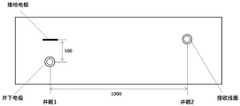
每个所述发射电极和接地电极之间的水平距离为100米,距离井口最近的发射电极与接地电极的之间的垂直距离至少为700米。The horizontal distance between each emitting electrode and the grounding electrode is 100 meters, and the vertical distance between the emitting electrode closest to the wellhead and the grounding electrode is at least 700 meters.
进一步地,每个所述发射电极均连接有激励电流发生器。Further, each of the emitter electrodes is connected with an excitation current generator.
进一步地,所述磁场接收单元包括若干个从上到下垂直排列的线圈式磁传感器,且相邻两个线圈式磁传感器之间通过连接螺套连接。Further, the magnetic field receiving unit includes several coil-type magnetic sensors vertically arranged from top to bottom, and two adjacent coil-type magnetic sensors are connected by connecting nuts.
一种基于电发射-磁接收的井间电磁探测方法,包括以下步骤:A cross-well electromagnetic detection method based on electric emission-magnetic reception, comprising the following steps:
S1、在待测区域中,布设发射模块及接收模块;S1. In the area to be tested, a transmitting module and a receiving module are arranged;
S2、通过激励电流发生器向地层中的发射电极施加预定频率的激励,使其与地层和接地电极构成回路,并在地层中产生电磁场;S2. Apply a predetermined frequency of excitation to the transmitting electrode in the formation through the excitation current generator, so that it forms a loop with the formation and the ground electrode, and generates an electromagnetic field in the formation;
S3、通过线圈式磁传感器接收电磁场,并将接收信息发送至接收机;S3. Receive the electromagnetic field through the coil type magnetic sensor, and send the received information to the receiver;
S4、通过接收机对接收到的电磁场信号进行处理获得有效磁场信息,并通过反演算法得到待测区域内地层的电导率分布情况,实现井间电磁探测。S4. Process the received electromagnetic field signal through the receiver to obtain effective magnetic field information, and obtain the conductivity distribution of the formation in the area to be measured through an inversion algorithm, so as to realize cross-well electromagnetic detection.
进一步地,所述步骤S3中,所述线圈式磁传感器接收到的电磁场为地层产生电磁场的BZ分量,且磁感应强度轴向分量BZ与发送至接收机的感应电动势|ε|的关系式为:Further, in the step S3, the electromagnetic field received by the coil-type magnetic sensor is the BZ component of the electromagnetic field generated by the formation, and the relationship between the axial component BZ of the magnetic induction and the induced electromotive force |ε| sent to the receiver for:

式中,f为频率,NR为线圈式磁传感器的匝数,aR为线圈式磁传感器的半径,BZ为磁感应强度轴向分量。In the formula, f is the frequency, NR is the number of turns of the coil magnetic sensor, aR is the radius of the coil magnetic sensor, and BZ is the axial component of the magnetic induction.
本发明的有益效果为:The beneficial effects of the present invention are:
1)本发明根据探测要求将发送模块和接收模块分设于两口井中,可以实现远距离的井间探测,解决了现有的“磁发射-磁接收”发射信号弱,测井深度浅,难以实现远距离探测的问题;1) The present invention separates the sending module and the receiving module in two wells according to the detection requirements, which can realize long-distance inter-well detection, and solve the problem that the existing "magnetic emission-magnetic reception" has weak emission signals and shallow logging depth, which is difficult to realize The problem of long-distance detection;
2)本发明系统结构可用于小口径的井间电磁探测,能够明显接收到信号,且该信号的变化能够有效反映地层中异常体的位置信息,因此本发明方法对于小口径远距离的固体金属矿探测有重要意义;2) The system structure of the present invention can be used for small-diameter cross-well electromagnetic detection, and the signal can be clearly received, and the change of the signal can effectively reflect the position information of the abnormal body in the formation. Mining exploration is of great significance;
3)本发明采用“电发射-磁接收”的原理,所采用的仪器体积小、操作简单、携带方便、发射信号强,且接收灵敏度高,能够有效地实现远距离井间电磁探测。3) The present invention adopts the principle of "electric emission-magnetic reception". The instrument adopted is small in size, simple in operation, easy to carry, strong in emission signal, and high in reception sensitivity, and can effectively realize long-distance cross-well electromagnetic detection.
附图说明Description of drawings
图1为本发明提供的基于电发射-磁接收的井间电磁探测系统俯视局部剖面示意图。Fig. 1 is a top view partial cross-sectional schematic diagram of a cross-well electromagnetic detection system based on electric emission-magnetic reception provided by the present invention.
图2为本发明提供的基于电发射-磁接收的井间电磁探测系统侧视局部剖面示意图。Fig. 2 is a side view partial cross-sectional schematic diagram of the cross-well electromagnetic detection system based on electric emission-magnetic reception provided by the present invention.
图3为本发明提供的发射电极在地层中产生电磁场的原理示意图。Fig. 3 is a schematic diagram of the principle of generating an electromagnetic field in the formation by the emitter electrode provided by the present invention.
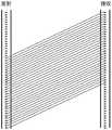
图4为本发明提供的线圈式磁传感器接收电磁场的原理示意图。FIG. 4 is a schematic diagram of the principle of receiving an electromagnetic field by a coil-type magnetic sensor provided by the present invention.
图5为本发明提供的“电发射-磁接收”原理示意图。Fig. 5 is a schematic diagram of the principle of "electric emission-magnetic reception" provided by the present invention.
图6为本发明提供的基于电发射-磁接收的井间电磁探测方法流程图。Fig. 6 is a flow chart of the cross-well electromagnetic detection method based on electric emission-magnetic reception provided by the present invention.
图7为本发明提供的实验结果示意图。Fig. 7 is a schematic diagram of the experimental results provided by the present invention.
具体实施方式detailed description
下面对本发明的具体实施方式进行描述,以便于本技术领域的技术人员理解本发明,但应该清楚,本发明不限于具体实施方式的范围,对本技术领域的普通技术人员来讲,只要各种变化在所附的权利要求限定和确定的本发明的精神和范围内,这些变化是显而易见的,一切利用本发明构思的发明创造均在保护之列。The specific embodiments of the present invention are described below so that those skilled in the art can understand the present invention, but it should be clear that the present invention is not limited to the scope of the specific embodiments. For those of ordinary skill in the art, as long as various changes Within the spirit and scope of the present invention defined and determined by the appended claims, these changes are obvious, and all inventions and creations using the concept of the present invention are included in the protection list.
如图1~2所示,一种基于电发射-磁接收的井间电磁探测系统,包括发射模块和接收模块;As shown in Figures 1 and 2, a cross-well electromagnetic detection system based on electric emission and magnetic reception includes a transmitting module and a receiving module;
发射模块,包括分别设置于井下的发射电极和地面的接地电极,用于在地层中产生电磁场;The transmitting module includes the transmitting electrode arranged in the downhole and the grounding electrode on the ground respectively, and is used to generate an electromagnetic field in the formation;
接收模块,包括相互连接的磁场接收单元和接收机,用于接收电磁场并分析磁场强弱情况,实现井间电磁探测。The receiving module includes an interconnected magnetic field receiving unit and a receiver, which are used to receive electromagnetic fields and analyze the strength of the magnetic field to realize cross-well electromagnetic detection.
在本实施例中,所述发射模块和接收模块分设于相距1000米的两口井中。In this embodiment, the transmitting module and the receiving module are separately arranged in two
在本实施例发射电极在电磁探测过程可移动至不同地层深度,每个所述发射电极和接地电极之间的水平距离为100米,距离井口最近的发射电极与接地电极的之间的垂直距离至少为700米。每个所述发射电极均连接有激励电流发生器。In this embodiment, the transmitting electrodes can be moved to different formation depths during the electromagnetic detection process. The horizontal distance between each transmitting electrode and the grounding electrode is 100 meters, and the vertical distance between the transmitting electrode closest to the wellhead and the grounding electrode is 100 meters. At least 700 meters. Each of the emitting electrodes is connected with an excitation current generator.
其中,如图3所示,置于井下的发射电极的直径只要小于井眼尺寸即可,激励电流发生器施加大的激励电流时,发射电极均可以产生较强的信号,在进行井间电磁探测时,井间电磁对于发射模块的要求是要产生足够强的信号,从而实现远距离传输,由于高频电磁波在地层中衰减较快,所以在本实施例中的元距离井间探测中采用低频电磁法,并且在接收模块侧也是采用同样的频率来接收电磁波。Among them, as shown in Figure 3, the diameter of the emitter electrode placed downhole should be smaller than the borehole size. When the excitation current generator applies a large excitation current, the emitter electrode can generate a strong signal. During detection, the interwell electromagnetic requirement for the transmitting module is to generate a sufficiently strong signal to achieve long-distance transmission. Since high-frequency electromagnetic waves attenuate quickly in the formation, the element-distance interwell detection in this embodiment uses Low-frequency electromagnetic method, and the receiving module side also uses the same frequency to receive electromagnetic waves.
如图4所示,本实施例中的磁场接收单元包括若干个从上到下垂直排列的线圈式磁传感器,且相邻两个线圈式磁传感器之间通过连接螺套连接,进而接收磁感应强度轴向分量Bz。具体地,在本实施例中,线圈式磁传感器在测试过程中是会移动的,从而测到不同位置的接收信号,连接螺套仅是为了将多个接收线圈连接在一起,构成阵列,提高电磁场探测的灵敏度。As shown in Figure 4, the magnetic field receiving unit in this embodiment includes several coil-type magnetic sensors arranged vertically from top to bottom, and two adjacent coil-type magnetic sensors are connected by connecting nuts to receive magnetic induction. Axial component Bz. Specifically, in this embodiment, the coil-type magnetic sensor can move during the testing process, so as to detect the receiving signals at different positions, and the connecting screw sleeve is only for connecting multiple receiving coils together to form an array and improve Sensitivity of electromagnetic field detection.
需要说明的是,在本实施例中,发送模块和接收模块安装并不是固定的,其是需要根据实验需求来确定,依据目标探测区域的位置来确定即可,一般是在目标探测区域设置多个发射点(发射电极)和接收点(线圈式磁传感器),至于设置数量,是根据探测需求来确定的,从而获得探测数据。It should be noted that in this embodiment, the installation of the sending module and the receiving module is not fixed, it needs to be determined according to the experimental requirements, and can be determined according to the position of the target detection area. A transmitting point (transmitting electrode) and a receiving point (coil type magnetic sensor), as for the number of settings, is determined according to the detection requirements, so as to obtain detection data.
实施例2:Example 2:
基于如图5所示的“电发射-磁接收”的原理示意图,本实施例中提供了一种基于实施例1中的系统实现井间电磁探测的方法,如图6所示,包括以下步骤:Based on the schematic diagram of the principle of "electrical emission-magnetic reception" as shown in Figure 5, this embodiment provides a method for realizing cross-well electromagnetic detection based on the system in Embodiment 1, as shown in Figure 6, including the following steps :
S1、在待测区域中,布设发射模块及接收模块;S1. In the area to be tested, a transmitting module and a receiving module are arranged;
S2、通过激励电流发生器向地层中的发射电极施加预定频率的激励,使其与地层和接地电极构成回路,并在地层中产生电磁场;S2. Apply a predetermined frequency of excitation to the transmitting electrode in the formation through the excitation current generator, so that it forms a loop with the formation and the ground electrode, and generates an electromagnetic field in the formation;
S3、通过线圈式磁传感器接收电磁场,并将接收信息发送至接收机;S3. Receive the electromagnetic field through the coil type magnetic sensor, and send the received information to the receiver;
S4、通过接收机对接收到的电磁场信号进行处理获得有效磁场信息,并通过反演算法得到待测区域内地层的电导率分布情况,实现井间电磁探测。S4. Process the received electromagnetic field signal through the receiver to obtain effective magnetic field information, and obtain the conductivity distribution of the formation in the area to be measured through an inversion algorithm, so as to realize cross-well electromagnetic detection.
上述步骤S3中,在保证发射模块已经发出较强的信号的前提下,只要接收系统满足一定的灵敏度和噪声水平要求,并选取干扰较小的实验环境,就能接收到信号,对接收到的信号进行滤波、放大等操作,即可获得有效信号。In the above step S3, under the premise of ensuring that the transmitting module has sent a strong signal, as long as the receiving system meets certain sensitivity and noise level requirements, and the experimental environment with less interference is selected, the signal can be received. The signal is filtered, amplified, etc., and an effective signal can be obtained.
由于线圈式磁传感器竖直放置,可看作一垂直磁偶极子源,因此线圈式磁传感器接收到的电磁场为地层产生电磁场的BZ分量,且磁感应强度轴向分量BZ与发送至接收机的感应电动势|ε|的关系式为:Since the coil-type magnetic sensor is vertically placed, it can be regarded as a vertical magnetic dipole source, so the electromagnetic field received by the coil-type magnetic sensor is the BZ component of the electromagnetic field generated by the formation, and the axial component BZ of the magnetic induction intensity is sent to the receiver The relational expression of the induced electromotive force |ε| of the machine is:

式中,f为频率,NR为线圈式磁传感器的匝数,aR为线圈式磁传感器的半径,BZ为磁感应强度轴向分量。In the formula, f is the frequency, NR is the number of turns of the coil magnetic sensor, aR is the radius of the coil magnetic sensor, and BZ is the axial component of the magnetic induction.
在上述步骤S4中,通过接收机采用反演算法对有效磁场信息进行处理,获得待测区域内地层的电导率分布情况,具体地,将接收到的磁场信号通过反演转换为对应的电导率值,进而获得地层分布情况。需要说明的是,本实施例中能够使用的反演算法包括很多种,采用效果好、精度高的算法即可。In the above step S4, the effective magnetic field information is processed by the receiver using the inversion algorithm to obtain the conductivity distribution of the formation in the area to be measured, specifically, the received magnetic field signal is converted into the corresponding conductivity by inversion value, and then obtain the stratigraphic distribution. It should be noted that there are many kinds of inversion algorithms that can be used in this embodiment, and the algorithm with good effect and high precision can be used.
实施例3:Example 3:
本实施例提供了基于上述探测系统及方法进行井间电磁探测的实例,通过接地电极向地下发射15.625Hz的方波信号,激励电流为30A,信号周期为0.064s,发射300个周期,总采集时间为19.2s,进而在电极与地层中构成回路,并产生电磁场。本实施例中选取15.625Hz的频点,是由于低频情况下电磁波的衰减相对较慢,有利于实现远距离传输,激励电流为30A也是为了保证发射足够强的信号。This embodiment provides an example of interwell electromagnetic detection based on the above-mentioned detection system and method. A 15.625Hz square wave signal is transmitted underground through the ground electrode, the excitation current is 30A, the signal period is 0.064s, and 300 cycles are transmitted. The total collection The time is 19.2s, and then a loop is formed between the electrode and the formation, and an electromagnetic field is generated. In this embodiment, the frequency point of 15.625 Hz is selected because the attenuation of electromagnetic waves is relatively slow at low frequencies, which is conducive to long-distance transmission. The excitation current is 30 A to ensure that a sufficiently strong signal is transmitted.
对于发射模块和接收模块的位置设置,发射模块中的发射点由井深1070米处开始向上移动,每10米为一个发射点,最后一个发射点为井深780米处,接收系统中线圈式磁传感器由井深880米处开始向上移动,每10米为一个接收采集点,最后一个接收点为井深590米处,发射点与接收点一一对应,共测得30组数据。For the position setting of the transmitting module and the receiving module, the transmitting point in the transmitting module starts to move upwards from the well depth of 1070 meters, and every 10 meters is a transmitting point, and the last transmitting point is at a well depth of 780 meters. The coil type magnetic sensor in the receiving system Starting from the well depth of 880 meters and moving upward, every 10 meters is a receiving collection point, and the last receiving point is at the depth of 590 meters. The transmitting point corresponds to the receiving point one by one, and a total of 30 sets of data have been measured.
基于上述实验设置,获得的实验结果如图7所示,此处仅展示一维实验结果,由实验结果可以看出数据出现两次突变,推断地层中存在两处异常体,后续通过进一步的二维甚至三维成像可以得到异常体的具体位置信息。Based on the above experimental settings, the obtained experimental results are shown in Fig. 7. Only the one-dimensional experimental results are shown here. It can be seen from the experimental results that there are two sudden changes in the data, and it is inferred that there are two abnormal bodies in the formation. Three-dimensional or even three-dimensional imaging can obtain the specific location information of the abnormal body.
Claims (4)
Translated fromChinesePriority Applications (1)
| Application Number | Priority Date | Filing Date | Title |
|---|---|---|---|
| CN202110632325.1ACN113376704B (en) | 2021-06-07 | 2021-06-07 | A cross-well electromagnetic detection system and method based on electric emission-magnetic reception |
Applications Claiming Priority (1)
| Application Number | Priority Date | Filing Date | Title |
|---|---|---|---|
| CN202110632325.1ACN113376704B (en) | 2021-06-07 | 2021-06-07 | A cross-well electromagnetic detection system and method based on electric emission-magnetic reception |
Publications (2)
| Publication Number | Publication Date |
|---|---|
| CN113376704A CN113376704A (en) | 2021-09-10 |
| CN113376704Btrue CN113376704B (en) | 2023-01-10 |
Family
ID=77576131
Family Applications (1)
| Application Number | Title | Priority Date | Filing Date |
|---|---|---|---|
| CN202110632325.1AActiveCN113376704B (en) | 2021-06-07 | 2021-06-07 | A cross-well electromagnetic detection system and method based on electric emission-magnetic reception |
Country Status (1)
| Country | Link |
|---|---|
| CN (1) | CN113376704B (en) |
Citations (4)
| Publication number | Priority date | Publication date | Assignee | Title |
|---|---|---|---|---|
| CN104131808A (en)* | 2014-07-16 | 2014-11-05 | 中国海洋石油总公司 | Device for positioning and detecting accident well on basis of transient electromagnetic method |
| CN105044792A (en)* | 2015-08-25 | 2015-11-11 | 长江大学 | Ground-well time-frequency electromagnetic exploration data acquisition apparatus and method |
| CN110471117A (en)* | 2019-09-26 | 2019-11-19 | 国科(重庆)仪器有限公司 | A kind of aviation electromagnetic detection system and method |
| CN112003590A (en)* | 2020-07-04 | 2020-11-27 | 电子科技大学 | High-power sinusoidal signal generation circuit and method for interwell electromagnetism |
Family Cites Families (9)
| Publication number | Priority date | Publication date | Assignee | Title |
|---|---|---|---|---|
| US6573722B2 (en)* | 2000-12-15 | 2003-06-03 | Schlumberger Technology Corporation | Method and apparatus for cancellation of borehole effects due to a tilted or transverse magnetic dipole |
| CA2524728C (en)* | 2005-10-28 | 2010-09-28 | Kjt Enterprises, Inc. | System for measuring earth formation resistivity through an electrically conductive wellbore casing |
| NO323889B1 (en)* | 2005-11-03 | 2007-07-16 | Advanced Hydrocarbon Mapping A | Process for mapping hydrocarbon reservoirs and apparatus for use in carrying out the process |
| CN102053280B (en)* | 2010-11-10 | 2013-05-01 | 吉林大学 | Nuclear magnetic resonance ground water detection system with reference coils and detection method |
| CN104614779B (en)* | 2015-01-16 | 2017-07-21 | 中国矿业大学 | A kind of multi-parameter electromagnetic method dynamic monitoring system and its method |
| US11022594B2 (en)* | 2018-04-24 | 2021-06-01 | Transtech Systems, Inc. | Parallel plate capacitor system for determining impedance characteristics of material under test (MUT) |
| CN111220927A (en)* | 2020-03-10 | 2020-06-02 | 中铁电气化局集团有限公司 | Wireless power supply transmission efficiency detection device, system and method |
| CN111983703B (en)* | 2020-07-24 | 2023-07-25 | 中国石油天然气集团有限公司 | Method, system and device for imaging electromagnetic measurement fluid between wells |
| CN112230291B (en)* | 2020-09-10 | 2021-10-15 | 电子科技大学 | Signal synchronization transceiver method and system for interwell electromagnetic detection |
- 2021
- 2021-06-07CNCN202110632325.1Apatent/CN113376704B/enactiveActive
Patent Citations (4)
| Publication number | Priority date | Publication date | Assignee | Title |
|---|---|---|---|---|
| CN104131808A (en)* | 2014-07-16 | 2014-11-05 | 中国海洋石油总公司 | Device for positioning and detecting accident well on basis of transient electromagnetic method |
| CN105044792A (en)* | 2015-08-25 | 2015-11-11 | 长江大学 | Ground-well time-frequency electromagnetic exploration data acquisition apparatus and method |
| CN110471117A (en)* | 2019-09-26 | 2019-11-19 | 国科(重庆)仪器有限公司 | A kind of aviation electromagnetic detection system and method |
| CN112003590A (en)* | 2020-07-04 | 2020-11-27 | 电子科技大学 | High-power sinusoidal signal generation circuit and method for interwell electromagnetism |
Non-Patent Citations (3)
| Title |
|---|
| Experimental research on transient electromagnetic wave transmission characteristics in single-hole;Ma Chunguang;;《2013 IEEE 11th International Conference on Electronic Measurement & Instruments》;20140220;全文* |
| 瞬变电磁法线源构建技术研究;杨璐;《中国优秀硕士学位论文全文数据库 (基础科学辑)》;20150515;A011-117* |
| 矿井瞬变电磁天线前后异常响应特征模拟实验研究;李俊等;《硅谷》;20111008(第19期);121-122* |
Also Published As
| Publication number | Publication date |
|---|---|
| CN113376704A (en) | 2021-09-10 |
Similar Documents
| Publication | Publication Date | Title |
|---|---|---|
| CN109209354B (en) | A method for far boundary detection of transient electromagnetic wave logging in time domain | |
| CN110208866B (en) | Ground well array type optical fiber time-frequency electromagnetic data acquisition device and data acquisition method thereof | |
| CN102156301B (en) | Advanced-prediction observation system while drilling | |
| CN109143390B (en) | A shallow transient electromagnetic fine exploration method based on geometric factor | |
| CN112415615B (en) | Time-frequency electromagnetic fracturing monitoring system and monitoring method based on distributed optical fiber sensing | |
| WO2012109844A1 (en) | Downhole time-domain pulsed electromagnetic method for detecting resistivity of stratum outside metal cased pipe | |
| CN106054258A (en) | Magnetic source ground-tunnel transient electromagnetic advanced detection method | |
| CN102565848B (en) | Method for detecting karst cave by utilizing resonance wave imaging | |
| CN105332697B (en) | A kind of coplanar coil array of array of measurement stratum vertical conductivity | |
| CN113655533B (en) | A sandstone-type uranium mine borehole transient electromagnetic logging device and logging method thereof | |
| CN215169955U (en) | Underground time domain or frequency domain multi-component electromagnetic measuring instrument based on graphene electromagnetic shielding | |
| CN104612671A (en) | Array induction coil system for measuring vertical formation conductivity | |
| CN102720484A (en) | While-drilling acoustic well-logging apparatus and well-logging method | |
| SONG et al. | Research on transient electromagnetic response of magnetic source in borehole | |
| CN111538093A (en) | Method for shallow surface detection and transient electromagnetic instrument | |
| CN112814668B (en) | A Formation Dip Estimation Method Based on Time Domain Electromagnetic Logging | |
| CN204855829U (en) | Data acquisition of electromagnetic survey frequently device during ground - well | |
| CN105891895B (en) | A kind of system and method determining sky wave propagation characteristic | |
| CN105781538B (en) | A kind of electromagnetic wave resistivity logging coil array | |
| CN113376704B (en) | A cross-well electromagnetic detection system and method based on electric emission-magnetic reception | |
| CN107024722B (en) | A kind of low-temperature superconducting magnetic source transient electromagnetic landform correcting method of lane based on abnormal ring | |
| CN211144481U (en) | An azimuth-while-drilling nuclear magnetic resonance logging device for geosteering | |
| CN116522072A (en) | Radar logging data processing method | |
| Dang et al. | Multi-coil array for long-distance cross-well electromagnetic detection | |
| CN116338805A (en) | A wellbore time-domain electromagnetic remote detection device and method |
Legal Events
| Date | Code | Title | Description |
|---|---|---|---|
| PB01 | Publication | ||
| PB01 | Publication | ||
| SE01 | Entry into force of request for substantive examination | ||
| SE01 | Entry into force of request for substantive examination | ||
| GR01 | Patent grant | ||
| GR01 | Patent grant |