CN113357985B - Spherical air charging spacer for blasting engineering and spaced charging method - Google Patents
Spherical air charging spacer for blasting engineering and spaced charging methodDownload PDFInfo
- Publication number
- CN113357985B CN113357985BCN202110588970.8ACN202110588970ACN113357985BCN 113357985 BCN113357985 BCN 113357985BCN 202110588970 ACN202110588970 ACN 202110588970ACN 113357985 BCN113357985 BCN 113357985B
- Authority
- CN
- China
- Prior art keywords
- lifting
- claw
- hole
- spacer
- buckle
- Prior art date
- Legal status (The legal status is an assumption and is not a legal conclusion. Google has not performed a legal analysis and makes no representation as to the accuracy of the status listed.)
- Active
Links
- 125000006850spacer groupChemical group0.000titleclaimsabstractdescription28
- 238000005422blastingMethods0.000titleclaimsabstractdescription19
- 238000000034methodMethods0.000titleclaimsabstractdescription8
- 210000000078clawAnatomy0.000claimsabstractdescription25
- 239000000463materialSubstances0.000claimsdescription7
- 230000000694effectsEffects0.000claimsdescription6
- 239000002360explosiveSubstances0.000claimsdescription5
- 238000009434installationMethods0.000claimsdescription5
- 238000005192partitionMethods0.000claimsdescription3
- 238000004880explosionMethods0.000claims1
- 239000000725suspensionSubstances0.000abstractdescription2
- 210000005069earsAnatomy0.000abstract1
- 239000003814drugSubstances0.000description3
- 238000005516engineering processMethods0.000description3
- 238000009412basement excavationMethods0.000description2
- 238000010276constructionMethods0.000description2
- 238000010586diagramMethods0.000description2
- 238000012856packingMethods0.000description2
- 230000000452restraining effectEffects0.000description2
- 239000011435rockSubstances0.000description2
- 235000017166Bambusa arundinaceaNutrition0.000description1
- 235000017491Bambusa tuldaNutrition0.000description1
- 241001330002BambuseaeSpecies0.000description1
- 235000015334Phyllostachys viridisNutrition0.000description1
- 239000011425bambooSubstances0.000description1
- 230000009286beneficial effectEffects0.000description1
- 229940079593drugDrugs0.000description1
- 238000005065miningMethods0.000description1
- 238000002156mixingMethods0.000description1
- 238000012986modificationMethods0.000description1
- 230000004048modificationEffects0.000description1
- 239000000843powderSubstances0.000description1
- 239000004575stoneSubstances0.000description1
- XLYOFNOQVPJJNP-UHFFFAOYSA-NwaterSubstancesOXLYOFNOQVPJJNP-UHFFFAOYSA-N0.000description1
Images


Classifications
- F—MECHANICAL ENGINEERING; LIGHTING; HEATING; WEAPONS; BLASTING
- F42—AMMUNITION; BLASTING
- F42D—BLASTING
- F42D1/00—Blasting methods or apparatus, e.g. loading or tamping
- F42D1/08—Tamping methods; Methods for loading boreholes with explosives; Apparatus therefor
- F42D1/22—Methods for holding or positioning for blasting cartridges or tamping cartridges
- F—MECHANICAL ENGINEERING; LIGHTING; HEATING; WEAPONS; BLASTING
- F42—AMMUNITION; BLASTING
- F42D—BLASTING
- F42D1/00—Blasting methods or apparatus, e.g. loading or tamping
- F42D1/08—Tamping methods; Methods for loading boreholes with explosives; Apparatus therefor
Landscapes
- Life Sciences & Earth Sciences (AREA)
- General Life Sciences & Earth Sciences (AREA)
- Engineering & Computer Science (AREA)
- General Engineering & Computer Science (AREA)
- Load-Engaging Elements For Cranes (AREA)
Abstract
Translated fromChinese
Description
Translated fromChinese技术领域technical field
本发明涉及工程爆破领域,特别是涉及一种爆破工程球状空气间隔装药器及间隔装药方法。The invention relates to the field of engineering blasting, in particular to a spherical air spacer for blasting engineering and a method for spacer charge.
背景技术Background technique
深孔爆破技术在大型土石方开挖工程中占有重要地位,广泛应用于路基开挖、矿山开采、水利施工作业中。相对于传统连续装药技术,采用间隔装药技术能够有效降低炸药单耗、减少爆破振动,并且可以降低炮孔内壁初始冲击压力峰值,避免矿岩过度粉碎,提高能量利用率,达到改善爆破效果,降低爆破成本的目的。目前市场上的空气间隔器单价高,使用率较低,我国矿山一般采用岩粉、竹筒、PVC管等材料代替空气间隔器,其爆破效果较差。Deep hole blasting technology occupies an important position in large-scale earth and stone excavation projects, and is widely used in roadbed excavation, mining, and water conservancy construction operations. Compared with the traditional continuous charging technology, the use of spaced charging technology can effectively reduce the unit consumption of explosives, reduce blasting vibration, and can reduce the initial impact pressure peak value of the inner wall of the blasthole, avoid excessive crushing of ore and rock, improve energy utilization, and improve blasting effect. , the purpose of reducing blasting costs. At present, the unit price of air spacers on the market is high, and the utilization rate is low. Generally, mines in my country use rock powder, bamboo tubes, PVC pipes and other materials to replace air spacers, and their blasting effect is poor.
发明内容SUMMARY OF THE INVENTION
本发明的目的在于提供一种成本低、操作简便、可靠性高的空气间隔装药器及间隔装药方法。The purpose of the present invention is to provide an air spacer and a spacer charge method with low cost, simple operation and high reliability.
为了达到上述目的,本发明采用以下技术方案实现:球状空气间隔装药器,包括爪型束缚装置、提拉卡扣、束缚带、高强度弹性气体球、吊绳、拉绳。In order to achieve the above-mentioned purpose, the present invention adopts the following technical solutions: a spherical air-spaced medicine charger, including a claw-type restraint device, a pull-up clasp, a restraint belt, a high-strength elastic gas ball, a hanging rope, and a pulling rope.
所述爪型束缚装置为刚性材料,束缚装置顶部为带吊耳固定盘,固定盘每隔90°外凸一段,凸出段开有凹槽和轴孔,固定盘通过转轴与四个束缚爪铰接,束缚爪尖设有限位孔,束缚爪内侧有防滑垫,防止气体球滑落。The claw-type restraint device is a rigid material, and the top of the restraint device is a fixed plate with lifting lugs. The fixed plate protrudes a section every 90°, and the convex section is provided with a groove and a shaft hole. The fixed plate passes through the rotating shaft and the four binding claws. Hinged, there is a limit hole at the tip of the binding claw, and there is a non-slip pad on the inside of the binding claw to prevent the gas ball from slipping.
所述提拉卡扣,包括插头和锁扣插销,插头的一端设有矩形孔槽,插头内部通过一个中间开有方孔的隔板,分隔为孔位和零件安装空间,零件安装空间内部设有可转动锁头,锁头两端分别通过转轴和弹簧固定在内壁上,在可转动锁头的弹簧固定端设有提拉开关;锁扣插销的一端设有矩形孔槽,另一端设有锁扣。使用时,将锁扣插销插入孔位内,将提拉开关放下,锁头的弹簧固定端卡住锁扣,此时提拉卡扣锁死;将提拉开关提起,锁头的弹簧固定端收回,提拉卡扣打开。The lifting buckle includes a plug and a locking pin. One end of the plug is provided with a rectangular hole slot, and the interior of the plug is divided into a hole position and a part installation space through a partition with a square hole in the middle. There is a rotatable lock head, the two ends of the lock head are respectively fixed on the inner wall by a rotating shaft and a spring, and a pull switch is arranged at the fixed end of the spring of the rotatable lock head; Latch. When in use, insert the latch pin into the hole, put down the lift switch, and the spring fixed end of the lock catches the lock, at this time the lift buckle is locked; lift the lift switch, the spring fixed end of the lock Retract it, and the lift buckle opens.
所述束缚带为非弹性柔性带,束缚带穿在束缚爪的限位孔中,束缚带的两端与提拉卡扣的插头矩形孔槽和锁扣插销矩形孔槽相连。The restraint belt is an inelastic flexible belt, the restraint belt is passed through the limit hole of the restraint claw, and the two ends of the restraint belt are connected with the rectangular hole groove of the plug and the rectangular hole groove of the lock buckle.
所述高强度弹性气体球原状为圆球形,气体球直径大于炮孔直径,在束缚装置外力作用下变形为椭球体,使整个间隔器径向最大尺寸小于炮孔直径,气体球外壁为防滑材料避免其从束缚装置或炮孔内壁滑落,影响间隔效果。The original shape of the high-strength elastic gas ball is spherical, the diameter of the gas ball is larger than the diameter of the blast hole, and deformed into an ellipsoid under the action of the external force of the restraint device, so that the maximum radial dimension of the entire spacer is smaller than the diameter of the blast hole, and the outer wall of the gas ball is made of anti-skid material. Prevent it from slipping off the restraint device or the inner wall of the blast hole, affecting the spacing effect.
所述吊绳与爪型束缚装置吊耳相连接,吊绳标有刻度,方便掌握间隔器下放深度,使间隔器可精确到达指定位置。The hanging rope is connected with the lifting lug of the claw-type restraint device, and the hanging rope is marked with a scale, which is convenient for grasping the lowering depth of the spacer, so that the spacer can accurately reach the designated position.
所述拉绳与提拉卡扣的开关相连接,拉绳提起,提拉卡扣打开,爪型束缚装置外力消失,高强度密闭弹性气体球由椭球体恢复为圆球体,使其卡在炮孔内,实现空气间隔。The pull rope is connected with the switch of the lifting buckle, the pull rope is lifted, the lifting buckle is opened, the external force of the claw restraint device disappears, and the high-strength airtight elastic gas ball is restored from an ellipsoid to a sphere, making it stuck in the gun. In the hole, the air gap is realized.
相应地,本发明还提供一种间隔装药方法,采用上述球状空气间隔装药器,步骤如下:Correspondingly, the present invention also provides a method for spaced charge, using the above-mentioned spherical air spacer charge, and the steps are as follows:
1)根据炮孔孔径调整束缚带长度,使锁固后的爪型束缚装置外径小于炮孔内径,打开提拉卡扣,将爪型束缚装置的四个爪撑开,将高强度弹性气体球放入爪型束缚装置内,将锁扣插销插入孔位内,将提拉开关放下;1) Adjust the length of the restraint belt according to the hole diameter of the blasting hole, so that the outer diameter of the claw-type restraint device after locking is smaller than the inner diameter of the blasting hole, open the pull-up buckle, spread the four claws of the claw-type restraint device, and release the high-strength elastic gas Put the ball into the claw restraint device, insert the lock pin into the hole, and put down the lift switch;
2)装填第一段炸药和起爆器材;2) Loading the first stage of explosives and detonating equipment;
3)通过吊绳将间隔器送入炮孔指定位置;3) Send the spacer to the designated position of the gun hole through the sling;
4)提拉拉绳,将提拉卡扣打开,使高强度弹性气体球由椭球体恢复为圆球体卡在炮孔内;4) Pull the pull rope, and open the pull buckle, so that the high-strength elastic gas ball is restored from an ellipsoid to a round sphere and is stuck in the blasthole;
5)提拉吊绳和拉绳,回收爪型束缚装置、提拉卡扣和束缚带;5) Pull the sling and the pull rope, and recover the claw restraint device, the pull buckle and the restraint belt;
6)进行后续装药及填塞工作;6) Carry out subsequent charging and packing;
7)重复1-6步,完成整个爆区间隔装药作业;7) Repeat steps 1-6 to complete the entire blasting area interval charging operation;
8)连接爆破网路,准备起爆。8) Connect to the blasting network and prepare to detonate.
本发明与现有技术相比,有益效果是:Compared with the prior art, the present invention has the following beneficial effects:
1、本发明主体采用气体球进行堵塞间隔,密闭性好,可以很好的避免露药,间隔效果好。1. The main body of the present invention uses gas balls to block the interval, which has good airtightness, can well avoid drug dew, and has a good interval effect.
2、本发明原理主要是利用气球体的自身形变实现,相对于通过药剂混合产生气体或外部设备充气而言,更加简便、廉价,且可靠性更高。2. The principle of the present invention is mainly realized by the self-deformation of the balloon body, which is simpler, cheaper, and more reliable than generating gas by mixing medicaments or inflating external equipment.
3、本发明吊绳标有刻度,施工人员吊装间隔器时容易掌握下放深度,间隔器安放位置更精确。3. The suspending rope of the present invention is marked with a scale, so the construction personnel can easily grasp the lowering depth when hoisting the spacer, and the placement position of the spacer is more accurate.
附图说明Description of drawings
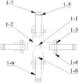
图1是本发明的结构示意图。Figure 1 is a schematic structural diagram of the present invention.
图2是本发明束缚装置结构示意图。FIG. 2 is a schematic view of the structure of the restraint device of the present invention.
图3是本发明束缚装置俯视图。Figure 3 is a top view of the restraint device of the present invention.
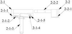
图4是本发明提拉卡扣打开状态俯视图。FIG. 4 is a top view of the open state of the pull buckle of the present invention.
图5是本发明提拉卡扣闭合状态俯视图。FIG. 5 is a top view of the closed state of the pull clasp of the present invention.
图6是本发明实施时示意图。FIG. 6 is a schematic diagram when the present invention is implemented.
附图标记说明:爪型束缚装置1;吊耳1-1;固定盘1-2;轴孔1-3;转轴1-4;防滑垫1-5;束缚爪1-6;限位孔1-7;凸出段凹槽1-8;提拉卡扣2;插头2-1;矩形孔槽2-1-1;弹簧2-1-2;提拉开关2-1-3;转轴2-1-4;可转动锁头2-1-5;锁扣插销2-2;矩形孔槽2-2-1;锁扣2-2-2;束缚带3;高强度弹性气体球4;吊绳5;拉绳6;炮孔7;炸药段8;起爆器材9;空气段10。DESCRIPTION OF REFERENCE NUMERALS: Claw-
具体实施方式Detailed ways
下面结合附图对本发明的具体实施方式作进一步说明:The specific embodiments of the present invention will be further described below in conjunction with the accompanying drawings:
如图1所示,本发明包括爪型束缚装置1、提拉卡扣2、束缚带3、高强度弹性气体球4、吊绳5、拉绳6。As shown in FIG. 1 , the present invention includes a claw-
如图2、图3所示,所述爪型束缚装置1为刚性材料,束缚装置顶部为带吊耳1-1的固定盘1-2,固定盘1-2每隔90°外凸一段,凸出段开有凹槽1-8和轴孔1-3,固定盘1-2通过转轴1-4与四个束缚爪1-6铰接,束缚爪尖设有限位孔1-7,束缚爪1-6内侧有防滑垫1-5,防止气体球4滑落。As shown in Figures 2 and 3, the claw-
如图4、图5所示,所述提拉卡扣2,包括插头2-1和锁扣插销2-2,插头2-1的一端设有矩形孔槽2-1-1,插头2-1内部通过一个中间开有方孔的隔板,分隔为孔位和零件安装空间,零件安装空间内部设有可转动锁头2-1-5,锁头2-1-5两端分别通过转轴2-1-4和弹簧2-1-2固定在内壁上,在可转动锁头2-1-5的弹簧固定端设有提拉开关2-1-3;锁扣插销2-2的一端设有矩形孔槽2-2-1,另一端设有锁扣2-2-2。使用时,将锁扣插销2-2插入孔位内,将提拉开关2-1-3放下,锁头的弹簧固定端卡住锁扣2-2-2,此时提拉卡扣2锁死;将提拉开关2-1-3提起,锁头的弹簧固定端收回,提拉卡扣2打开。As shown in FIG. 4 and FIG. 5 , the
如图1所示,所述束缚带3为非弹性柔性带,束缚带3穿在束缚爪1-6的限位孔1-7中,束缚带3的两端与提拉卡扣2的插头矩形孔槽2-1-1和锁扣插销矩形孔槽2-2-1相连。As shown in FIG. 1 , the
如图1、图6所示,所述高强度弹性气体球4原状为圆球形,气体球直径大于炮孔直径,在束缚装置1外力作用下变形为椭球体,使整个间隔器径向最大尺寸小于炮孔直径,气体球4外壁为防滑材料避免其从束缚装置1或炮孔7内壁滑落,影响间隔效果。As shown in Figures 1 and 6, the high-strength
如图1、图6所示,所述吊绳5与爪型束缚装置吊耳1-1相连接,吊绳5标有刻度,方便掌握间隔器下放深度,使间隔器可精确到达指定位置。As shown in Figures 1 and 6, the suspending
如图1、图6所示,所述拉绳6与提拉卡扣的开关2-1-3相连接,拉绳6提起,提拉卡扣2打开,爪型束缚装置1外力消失,高强度弹性气体球4由椭球体恢复为圆球体,使其卡在炮孔7内,实现空气间隔。As shown in FIG. 1 and FIG. 6 , the
相应地,本发明还提供一种间隔装药方法,采用上述球状空气间隔装药器,步骤如下:Correspondingly, the present invention also provides a method for spaced charge, using the above-mentioned spherical air spacer charge, and the steps are as follows:
1)根据炮孔7的孔径大小调整束缚带3的长度,使锁固后的爪型束缚装置1的外径小于炮孔7的内径,打开提拉卡扣2,将爪型束缚装置的四个爪1-6撑开,将高强度弹性气体球4放入爪型束缚装置1内,将锁扣插销2-2插入孔位内,将提拉开关2-1-3放下;1) Adjust the length of the
2)装填第一段炸药8和起爆器材9;2) Loading the
3)通过吊绳5将高强度弹性气体球4送入炮孔7的指定位置;3) send the high-strength
4)提拉拉绳6,将提拉卡扣2打开,使高强度弹性气体球4由椭球体恢复为圆球体卡在炮孔7内;4) Pull the
5)提拉吊绳5和拉绳6,回收爪型束缚装置1、提拉卡扣2和束缚带3;5) Pull the
6)进行后续装药及填塞工作;6) Carry out subsequent charging and packing;
7)重复1-6步,完成整个爆区间隔装药作业;7) Repeat steps 1-6 to complete the entire blasting area interval charging operation;
8)连接爆破网路,准备起爆。8) Connect to the blasting network and prepare to detonate.
以上所述,仅是本发明的基本原理,并非对本发明作任何限制,凡是根据本发明技术实质对以上实施例所作的任何简单修改、变更以及等效结构变化,均仍属于本发明技术方案的保护范围内。The above is only the basic principle of the present invention and does not limit the present invention. Any simple modifications, changes and equivalent structural changes made to the above embodiments according to the technical essence of the present invention still belong to the technical solutions of the present invention. within the scope of protection.
Claims (3)
Priority Applications (1)
| Application Number | Priority Date | Filing Date | Title |
|---|---|---|---|
| CN202110588970.8ACN113357985B (en) | 2021-05-28 | 2021-05-28 | Spherical air charging spacer for blasting engineering and spaced charging method |
Applications Claiming Priority (1)
| Application Number | Priority Date | Filing Date | Title |
|---|---|---|---|
| CN202110588970.8ACN113357985B (en) | 2021-05-28 | 2021-05-28 | Spherical air charging spacer for blasting engineering and spaced charging method |
Publications (2)
| Publication Number | Publication Date |
|---|---|
| CN113357985A CN113357985A (en) | 2021-09-07 |
| CN113357985Btrue CN113357985B (en) | 2022-06-07 |
Family
ID=77528006
Family Applications (1)
| Application Number | Title | Priority Date | Filing Date |
|---|---|---|---|
| CN202110588970.8AActiveCN113357985B (en) | 2021-05-28 | 2021-05-28 | Spherical air charging spacer for blasting engineering and spaced charging method |
Country Status (1)
| Country | Link |
|---|---|
| CN (1) | CN113357985B (en) |
Citations (11)
| Publication number | Priority date | Publication date | Assignee | Title |
|---|---|---|---|---|
| US6386111B1 (en)* | 1996-11-04 | 2002-05-14 | Advanced Blasting Technology, Inc. | Stemming arrangement and method for blast holes |
| RU2235971C1 (en)* | 2003-07-25 | 2004-09-10 | Федотенко Сергей Михайлович | Method of dispersion of a charge in a borehole |
| CN205897977U (en)* | 2016-06-17 | 2017-01-18 | 福州大学 | Big gun hole powder charge air space device |
| CN107631671A (en)* | 2017-11-06 | 2018-01-26 | 宿州云宏建设安装有限公司 | A kind of engineering explosion blasthole spaced loading device |
| CN108007287A (en)* | 2017-12-28 | 2018-05-08 | 中国电建集团成都勘测设计研究院有限公司 | Deep hole explosive airspace device |
| CN109186389A (en)* | 2018-10-29 | 2019-01-11 | 武汉大学 | A kind of blasthole blocking up method |
| CN208591511U (en)* | 2018-06-11 | 2019-03-12 | 徐章翊 | A kind of clamping and fixing device of ball inflating |
| CN110296640A (en)* | 2019-08-01 | 2019-10-01 | 中国矿业大学(北京) | A kind of rich water deep hole blasting isolation means for loading and its application method |
| CN110332867A (en)* | 2019-08-03 | 2019-10-15 | 贵州久远爆破工程有限责任公司 | A kind of air bench blasting radial air interval charging device |
| CN110715587A (en)* | 2019-11-19 | 2020-01-21 | 中国电建集团成都勘测设计研究院有限公司 | Air spaced charging auxiliary device for step blasting |
| CN212557544U (en)* | 2020-07-20 | 2021-02-19 | 温州朗盛工程塑料有限公司 | A reusable nylon cable tie |
Family Cites Families (1)
| Publication number | Priority date | Publication date | Assignee | Title |
|---|---|---|---|---|
| US11465366B2 (en)* | 2019-10-02 | 2022-10-11 | Ocean Rodeo Sports Inc. | Quick release leash |
- 2021
- 2021-05-28CNCN202110588970.8Apatent/CN113357985B/enactiveActive
Patent Citations (11)
| Publication number | Priority date | Publication date | Assignee | Title |
|---|---|---|---|---|
| US6386111B1 (en)* | 1996-11-04 | 2002-05-14 | Advanced Blasting Technology, Inc. | Stemming arrangement and method for blast holes |
| RU2235971C1 (en)* | 2003-07-25 | 2004-09-10 | Федотенко Сергей Михайлович | Method of dispersion of a charge in a borehole |
| CN205897977U (en)* | 2016-06-17 | 2017-01-18 | 福州大学 | Big gun hole powder charge air space device |
| CN107631671A (en)* | 2017-11-06 | 2018-01-26 | 宿州云宏建设安装有限公司 | A kind of engineering explosion blasthole spaced loading device |
| CN108007287A (en)* | 2017-12-28 | 2018-05-08 | 中国电建集团成都勘测设计研究院有限公司 | Deep hole explosive airspace device |
| CN208591511U (en)* | 2018-06-11 | 2019-03-12 | 徐章翊 | A kind of clamping and fixing device of ball inflating |
| CN109186389A (en)* | 2018-10-29 | 2019-01-11 | 武汉大学 | A kind of blasthole blocking up method |
| CN110296640A (en)* | 2019-08-01 | 2019-10-01 | 中国矿业大学(北京) | A kind of rich water deep hole blasting isolation means for loading and its application method |
| CN110332867A (en)* | 2019-08-03 | 2019-10-15 | 贵州久远爆破工程有限责任公司 | A kind of air bench blasting radial air interval charging device |
| CN110715587A (en)* | 2019-11-19 | 2020-01-21 | 中国电建集团成都勘测设计研究院有限公司 | Air spaced charging auxiliary device for step blasting |
| CN212557544U (en)* | 2020-07-20 | 2021-02-19 | 温州朗盛工程塑料有限公司 | A reusable nylon cable tie |
Also Published As
| Publication number | Publication date |
|---|---|
| CN113357985A (en) | 2021-09-07 |
Similar Documents
| Publication | Publication Date | Title |
|---|---|---|
| CN103759603B (en) | Hydraulic pressure is from spalling Self-closing lock dust-proof friction and Extrusion type perforation plugging device | |
| CN109186389B (en) | Blast hole blocking method | |
| CN106152887A (en) | Inflation expanding perforation plugging device certainly for tunnel deep hole blasting | |
| CN113357985B (en) | Spherical air charging spacer for blasting engineering and spaced charging method | |
| CN105865278B (en) | A kind of blasting engineering Blast hole plug | |
| CN203605839U (en) | Explosive charging device for deep hole blasting of coal mine | |
| CN204514208U (en) | Water resistant is cracked multistage spalling gripper formula perforation plugging device | |
| CN108413824A (en) | A kind of simple blasthole plugging device of bench blasting and its application method | |
| CN205897977U (en) | Big gun hole powder charge air space device | |
| CN203083464U (en) | Shot hole wedge-shaped body blocking device | |
| CN213811990U (en) | Self-sealing type orifice clamping device | |
| CN112611282A (en) | Deep hole blasting charging hole sealing method | |
| CN109387126B (en) | An uncoupled energy gathering spacer and its structure used in blastholes in non-coal mines | |
| CN209672967U (en) | hole plug spacer | |
| CN202255142U (en) | Blasthole explosion combined spacer | |
| CN116576743A (en) | Method for eliminating carbon monoxide product in airbag overhead blasting operation | |
| CN211060754U (en) | Metal mine tunnel driving blast hole blocking device | |
| CN207963658U (en) | A kind of fracturing expansion tube | |
| CN214247323U (en) | Water-sand-gunpowder coupling blasting permeability increasing device for coal mine | |
| CN115854807B (en) | A device for preventing explosives from scattering upward in a blast hole and a method of using the device | |
| CN210603009U (en) | Uncoupled explosive-charging spacer in blast hole | |
| CN211824109U (en) | Device is clogged to tunnel blasting construction big gun hole | |
| CN203811060U (en) | Tamping bar for ultra-deep hole blasting | |
| CN221571264U (en) | Device suitable for weak surrounding rock can be fast accurate location protection bottom plate eye | |
| CN213543371U (en) | Blast hole plugging device |
Legal Events
| Date | Code | Title | Description |
|---|---|---|---|
| PB01 | Publication | ||
| PB01 | Publication | ||
| SE01 | Entry into force of request for substantive examination | ||
| SE01 | Entry into force of request for substantive examination | ||
| GR01 | Patent grant | ||
| GR01 | Patent grant |